EP3533582B1 - Transport container with inmould film - Google Patents
Transport container with inmould film Download PDFInfo
- Publication number
- EP3533582B1 EP3533582B1 EP18159712.1A EP18159712A EP3533582B1 EP 3533582 B1 EP3533582 B1 EP 3533582B1 EP 18159712 A EP18159712 A EP 18159712A EP 3533582 B1 EP3533582 B1 EP 3533582B1
- Authority
- EP
- European Patent Office
- Prior art keywords
- inmould
- film
- region
- foil
- relief element
- Prior art date
- Legal status (The legal status is an assumption and is not a legal conclusion. Google has not performed a legal analysis and makes no representation as to the accuracy of the status listed.)
- Active
Links
Images


Classifications
-
- B—PERFORMING OPERATIONS; TRANSPORTING
- B29—WORKING OF PLASTICS; WORKING OF SUBSTANCES IN A PLASTIC STATE IN GENERAL
- B29C—SHAPING OR JOINING OF PLASTICS; SHAPING OF MATERIAL IN A PLASTIC STATE, NOT OTHERWISE PROVIDED FOR; AFTER-TREATMENT OF THE SHAPED PRODUCTS, e.g. REPAIRING
- B29C45/00—Injection moulding, i.e. forcing the required volume of moulding material through a nozzle into a closed mould; Apparatus therefor
- B29C45/14—Injection moulding, i.e. forcing the required volume of moulding material through a nozzle into a closed mould; Apparatus therefor incorporating preformed parts or layers, e.g. injection moulding around inserts or for coating articles
- B29C45/1418—Injection moulding, i.e. forcing the required volume of moulding material through a nozzle into a closed mould; Apparatus therefor incorporating preformed parts or layers, e.g. injection moulding around inserts or for coating articles the inserts being deformed or preformed, e.g. by the injection pressure
- B29C2045/14237—Injection moulding, i.e. forcing the required volume of moulding material through a nozzle into a closed mould; Apparatus therefor incorporating preformed parts or layers, e.g. injection moulding around inserts or for coating articles the inserts being deformed or preformed, e.g. by the injection pressure the inserts being deformed or preformed outside the mould or mould cavity
-
- B—PERFORMING OPERATIONS; TRANSPORTING
- B29—WORKING OF PLASTICS; WORKING OF SUBSTANCES IN A PLASTIC STATE IN GENERAL
- B29C—SHAPING OR JOINING OF PLASTICS; SHAPING OF MATERIAL IN A PLASTIC STATE, NOT OTHERWISE PROVIDED FOR; AFTER-TREATMENT OF THE SHAPED PRODUCTS, e.g. REPAIRING
- B29C45/00—Injection moulding, i.e. forcing the required volume of moulding material through a nozzle into a closed mould; Apparatus therefor
- B29C45/14—Injection moulding, i.e. forcing the required volume of moulding material through a nozzle into a closed mould; Apparatus therefor incorporating preformed parts or layers, e.g. injection moulding around inserts or for coating articles
- B29C2045/1486—Details, accessories and auxiliary operations
- B29C2045/14901—Coating a sheet-like insert smaller than the dimensions of the adjacent mould wall
- B29C2045/14918—Coating a sheet-like insert smaller than the dimensions of the adjacent mould wall in-mould-labelling
-
- B—PERFORMING OPERATIONS; TRANSPORTING
- B29—WORKING OF PLASTICS; WORKING OF SUBSTANCES IN A PLASTIC STATE IN GENERAL
- B29L—INDEXING SCHEME ASSOCIATED WITH SUBCLASS B29C, RELATING TO PARTICULAR ARTICLES
- B29L2031/00—Other particular articles
- B29L2031/712—Containers; Packaging elements or accessories, Packages
- B29L2031/7134—Crates, e.g. for bottles
Definitions
- the invention relates to a transport container, in particular a bottle crate for receiving beverage bottles or bottle containers, and to a method for producing such a transport container.
- a transport container is known with a container base body which has a bottom and four side walls, at least one of the side walls having a base and at least one relief element raised with respect to the base or at least one relief element recessed with respect to the base. It is provided that the side wall has one or more inmould film (s) that at least partially cover the base area and the relief element or the inverted relief element.
- the in-mold film disclosed covers an offset structure projecting into the wall plane, for example a wood grain, and at the same time text elements which are raised and / or recessed relative to the base area. Both the offset structure protruding into the plane of the wall and the raised and / or recessed text elements have a maximum offset height of 2 mm with respect to the base area.
- the maximum offset height of 2 mm is due to the manufacturing process of the transport container, in which the inmould film is inserted into an injection molding tool and the plastic forming the container base is back-molded.
- the invention is based on the object of creating a transport container and a method for its production which overcome the disadvantages of the prior art.
- a bottle crate for receiving beverage bottles or bottle containers comprising a container base body which has a bottom and four side walls
- at least one of the side walls has a base area and at least one relief element raised with respect to the base area or at least one with respect to the
- the base area has a recessed inverted relief element
- the side wall having at least one inmould film that at least partially covers the base area and the relief element or the inverted relief element, and wherein the inmould film has a first area assigned to the base area and a relief element or an inverted relief element assigned second area.
- the inmould film has at least one well-defined compensating recess in a transition area from the first area to the second area.
- “Well-defined” means either the shape or the size or also the shape and size of the compensation recess.
- the well-defined compensation recess of the in-mold film is well-defined in particular to the effect that it is determined in shape and size in a preprocessing step of the in-mold film before the in-mold film is back-injected in the injection molding tool.
- the well-defined compensation recess is therefore created by preconditioning the inmould film.
- the preconditioning of the inmould film ensures that the well-defined compensation recess is in The desired shape and size is located in the desired location, namely in the transition area from the first area to the second area of the inmould film.
- the preconditioning has the advantageous effect that during injection molding in the transition area from the first to the second area the pressure on the in-mold film is reduced, so that an undefined tearing of the in-mold film and an associated distortion of the printing in the area of the relief element or the inverted element are targeted Relief elements is counteracted.
- the well-defined recess is formed by an area with a reduced film thickness.
- preconditioning is applied in the form of an area with reduced film thickness, or it is added to the in-mold film by manipulation, for example by a robot device, before it is inserted into the injection molding tool.
- the area with reduced film thickness is stretched, so that after injection molding there is still an area with reduced film thickness without the in-mold film tearing in this area.
- the well-defined compensating recess is formed by an opening in the inmould film.
- the opening in the in-mold film can be added to the in-mold film, for example, from an opening already present when the in-mold film is fed to the injection molding element as a corresponding preconditioning of the in-mold film, or by manipulation, for example by a robot device, before it is inserted into the injection molding tool Opening.
- the opening is created by a well-defined tearing of a preconditioning in the form of an area with a reduced film thickness.
- the opening in the in-mold film is already present as preconditioning when the in-mold film is inserted into the injection molding tool, the opening can enlarge during injection molding due to the pressures acting on the film or connect to other openings, whereby this is a process that leads to a well-defined compensation recess within the meaning of the invention.
- the opening for example, will tear in a direction perpendicular to the train, or will tear in a direction in which there is another opening nearby.
- the film can therefore tear during injection molding, the tearing being advantageously restricted to the area defined by the preconditioning, i.e. H. takes place spatially in the area of the preconditioning and is determined by this.
- the preconditioning in the form of the area with reduced film thickness can be formed, for example, by punching or by chipping.
- it can comprise a film hinge area.
- the preconditioning in the form of the opening can also be formed by punching.
- the preconditioning can be formed in the form of the opening by a perforation, which means a multiplicity of holes along a predetermined line.
- the preconditioning can be formed by a cut.
- the well-defined compensation recess completely surrounds the relief element or the inverted relief element.
- the well-defined compensation recess partially surrounds the relief element or the inverted relief element.
- the inmould film has webs in the transition area from the first area to the second area which connect the first area and the second area to one another.
- the first area of the in-mold film is advantageously connected to the second area of the in-mold film in such a way that the print image of the in-mold film, which covers the relief element or inverted relief element, can be placed on it in a targeted manner without it comes to an unwanted lateral offset.
- the webs are preferably designed from 50 ⁇ m to 1 mm wide. As a result, the impression that results from the presence of the webs on the transition area is shaped as little as possible.
- the first and second areas are connected to one another at a large number of locations, for example at more than twenty locations.
- the first and second areas are connected to one another at fewer than ten points, fewer than five points, at four, three, in particular at two points, at one point or at no point.
- the visual impression of the transition area, in which the relief element rises or the inverted relief element is sunk is advantageously influenced by the webs at only a few points or at no point at all.
- the relief element or the inverted relief element is advantageously more than 0.5 mm, preferably more than 1 mm, more preferably more than 1.5 mm, even more preferably more than 2 mm and in particular from 2 mm to 5 mm, from 2 mm to 4 mm or from 2 mm to 3 mm raised or recessed from the base area.
- the relief element or the inverted relief element can have a significantly stronger profile, i.e. have a greater maximum offset than previous in-mold films, without the visual impression of the print image on the in-mold film in the second areas, in which the in-mold film covers the relief elements or inverted relief elements, is impaired.
- the relief element or inverted relief element can, for. B. a letter and / or a symbol, a logo, a brand or even an advertising lettering.
- the raised relief elements are less raised than the base of the side wall compared to the bumper edge or bumper strips.
- a large number or all of the relief elements and / or inverted relief elements that are provided on the transport container are covered with one or more inmould films.
- a large number of preconditions can advantageously be provided along the contours of all relief elements or inverted relief elements so that the inmould film in the first areas in which it covers the base area and in the second areas in which it inverts the relief elements or Relief elements covered, not cracking uncontrollably.
- the inmould film has a lacquer layer.
- lacquered in-mold films which already have a lacquer layer before back-molding, it has not yet been possible to arrange these on side walls with relief elements or inverted relief elements.
- Well-defined compensation recesses in the transition areas advantageously prevent the lacquer layer from bursting or tearing during back-molding, so that the present invention provides completely new design options for the transport container.
- the inmould film has a lamination.
- laminated in-mold films that already have a lamination before back-injection, it has not been possible to arrange them on side walls with relief elements that are raised by more than 2 mm or with inverted relief elements that are recessed by more than 2 mm.
- Well-defined compensation recesses in the transition areas advantageously prevent the lamination from breaking during the injection molding process, so that the present invention enables completely new visual impressions of the transport container.
- the inmould film can partially or completely have a matt effect.
- the inmould film has a matt effect only in the first area or only in the second area.
- the inmould film is matt in the first area and high-gloss in the second area or vice versa.
- a matt effect of the in-mold film can be produced, for example, by a structuring which is brought about in the injection molding process by embossing a structure on the tool jaw.
- Structures whose grain size corresponds roughly to a 250 grain with structure sizes of 10 ⁇ m to 80 ⁇ m lead to a matt-looking surface of the inmould film.
- Extremely smooth sections of the base on the other hand, create a glossy look in the inmould film.
- Suitable structures located on the tool jaw are, for example, erosion, in particular erosion according to VDI standards such as e.g. B. VDI 36.
- Alternative suitable structures located on the tool jaw can include brushed, grained, etched, and / or milled structures in a corresponding grain size.
- the matt effect can also be inherent in or on the inmould film before injection molding.
- the matt effect can, for. B. by using a translucent inmould film with a structured surface and / or by color printing or application of a lacquer.
- the structuring of the surface can be created, for example, by passing the inmould film through a pair of rollers, with two interlocking pressure rollers with a structured surface deforming the translucent film from both sides and thereby doubling the depth (e.g. -0.5 mm) or elevation (e.g. + 0.5 mm) without overstretching the film.
- the roller can also be designed in such a way that structured and unstructured surfaces lie next to one another.
- the base surface can be made smooth or in particular have a brushed, eroded, grained, etched, line-polished, high-gloss polished and / or milled 3D background structure.
- the 3D background structure can for example include features that are raised and / or recessed less than 1 mm, in particular 0.5 mm.
- the 3D background structure can in particular include planar components, which z. B. natural and / or industrial surface structures are modeled, for example wood grain structures, stone or granite patterns, checkered plate surfaces or the like.
- each side of the transport container is provided with at least one inmould film.
- In-mold foils that run around an edge or corner of the transport container are also possible.
- the side wall has two at least partially one above the other at least partially each covering the base and the relief element or the inverted relief element covering inmould films, one or both of the inmould films in the transition area from the first area to the second area have at least one well-defined compensation recess. It can be provided that the side wall has two in-mold foils lying on top of one another over the entire surface or two in-mold foils which only partially overlap.
- the two inmould films have well-defined compensation cutouts, the well-defined compensation cutouts being arranged one above the other.
- one or both inmould films have a lamination or coating and have well-defined compensation recesses in order to prevent impairment of the lacquer layer or the lamination.
- an inmould film is also provided for use in a previously described transport container, the inmould film having at least one preconditioning in a transition area from the first area to the second area.
- the inmould film has a thickness of 5 ⁇ m to 190 ⁇ m, for example.
- the inmould film can have a thickness of 60 ⁇ m to 110 ⁇ m.
- a PE film polyethylene film
- PP film polypropylene film
- PET film polyethylene terephthalate film
- the in-mold film can be printed, for example, with offset printing and / or with flexographic printing and / or with gravure printing and / or with digital printing and / or with screen printing.
- offset printing provision can be made for only the area to be provided with a basic white color print on which printed information, e.g. B. letters or logos is located.
- an inmould film in which the base film has a first print on the side facing the container base body and has a second print on the side facing away from the container base body.
- the shape and color of the first printing and the second printing correspond to one another.
- the first printing layer can advantageously maintain the optical effect so that the consumer does not notice the defect.
- the base film of the inmould film is colored translucent in the color of the container base body. Furthermore, the base film of the inmould film is preferably equipped with heat and light stabilizers (HALS stabilizers).
- HALS stabilizers heat and light stabilizers
- the matt effect can, for. B. be generated by a translucent inmould film with a structured surface and / or by a color print or application of a lacquer.
- the structured surface can be produced, for example, by passing the base film or in-mold film through a pair of rollers, with two interlocking rollers with a structured surface deforming the translucent film from both sides and thereby doubling the depth (e.g. -0.5 mm) or Create an increase (e.g. + 0.5 mm) without overstretching the film.
- the roller can also be designed in such a way that structured and unstructured surfaces lie next to one another.
- the PE, PP or PET base film is provided with a lamination or with a protective lacquer layer.
- Laminated in-mold films in which the base film is accommodated in a kind of envelope, are also possible. Laminations of this type and also protective varnishes help to protect the printed layers of the base film against damage, for example from components of a transport device scratching past, from stacking and palletizing with other transport containers or in everyday use.
- a laminated film is understood to mean a film in which the base film is covered with a plastic protective layer, which can optionally also have an adhesion-promoting underside.
- the lamination can be implemented using a transparent PET film.
- the lamination can also be done with a PP film.
- a transparent film can be provided.
- IML films made exclusively from PE or PP are used, recycling of the transport container is also advantageously possible without so-called downcycling.
- the lamination of the in-mold film can also be equipped with heat and light stabilizers (HALS stabilizers).
- HALS stabilizers heat and light stabilizers
- the lamination or the protective lacquer layer can also be printed.
- the inmould film supplied in step a) has at least one preconditioning in a transition area from the first area to the second area.
- the well-defined compensating recess is advantageously formed in the in-mold film in the transition area from the first area to the second area.
- the inmould film is fed to the injection molding tool as a strip product, in particular a roll product.
- the provision of the inmould films as tape goods, in particular roll goods has advantages in production, storage and transport, since the isolation of the inmould films does not take place at the supplier's premises.
- the inmould films are separated by means of a robot device. Compared to manual separation, this means a gain in precision and speed.
- the use of the robotic device to insert the inmould films into the The mold jaw of the injection molding tool enables the inmould film to be positioned particularly precisely in the injection molding tool, so that the desired appearance of the transport container is ensured, with a high throughput at the same time.
- the in-mold film can be fed in manually.
- the in-mold films are fed by a feed device which, for example, can comprise spools, conveyor rollers and / or wheels.
- the in-mold films can be guided by rollers or cylinders that rest over the entire surface, or by one or more wheels that are coupled to one another and that lie on the inmould film at specific points.
- the inmould film, starting from a roll is passed through a system of several rollers or wheels until it reaches the robot device.
- a horizontal guide, a vertical guide or a section-wise horizontal and vertical guide can be provided.
- the inmould film can initially be unwound from a high roll by means of a lower pair of rolls or wheels and then, if necessary, can be continued horizontally by further pairs of rolls or wheels.
- the removal position by the robot device can be a horizontal position or a vertical position of the inmould film. In the removal position, but also in front of it, the inmould film can be counter-supported on the back on the side opposite the robot device, for example by a rear wall, a support or by a magazine, in order to support the manipulation by the robot device on the rear.
- the inmould film in the form of tape goods, in particular roll goods can be present in wound form on a spindle or roll.
- it can also be placed on a carrier material, e.g. B. another plastic film can be arranged, from which it is separated in the step of isolation.
- the robot device can have both a robot arm and a number of interacting robot arms, the controls of which are coordinated with one another. At least one robot arm of the robot device can be designed to separate the inmould films and has corresponding devices for this purpose. The same or a further robot arm of the robot device can be designed to insert the separated inmould film into a tool jaw of the injection molding tool for subsequent back injection and has further corresponding devices for this purpose.
- at least one robot arm of the robot device can have a detection device which includes, for example, cameras, CCD bars or other suitable sensors in order to identify the inmould films to be separated.
- At least one robot arm of the robot device can have a manipulation head, which can in particular comprise suction, gripping, cutting, punching and / or chipping devices in order to enable the inmould film to be separated.
- This or a further manipulating head of the robot device can also be set up, e.g. B. by means of joints and appropriate controls to transfer the isolated in-mold film to the injection molding tool and position it in the injection molding tool.
- the tool jaw of the injection molding tool can be designed in one piece or in several pieces and can include both flat and angular areas. You can define both a side wall of the later transport container, but also a corner area of the transport container or several, z. B. also circumferential side walls.
- the in-mold foils supplied to the injection molding tool as strip goods have outer contours with preconditions in the form of areas with reduced foil thicknesses or openings.
- the preconditions have the effect, for example, that the outer contours can be recognized in a simple manner by the robot device.
- the robot device detects the preconditions by optical sensors, e.g. B. by a camera, or for transparent films z. B. by a confocal measuring device.
- the robot device carries out the preconditions by determining the thickness of the inmould film, e.g. B. by means of non-contact methods, e.g. B. detects by means of inductive or capacitive sensors, or by scanning.
- the robot device separates the inmould films by means of vacuum suction or by means of electrostatic charging according to the outer contours.
- the preconditioning of the inmould films and the vacuum channels on the manipulating head of the The robot device can be designed and coordinated with one another in such a way that the in-mold film is separated from the tape according to its outer contour by applying the vacuum.
- an electrostatic field is applied to the manipulating head of the robot device, the inmould film being separated from the tape by the static charge.
- the preconditions can in particular be designed as thin film hinges or as a perforation or as extended openings with webs which tear when a defined tensile stress is applied.
- the robot device separates the inmould films in accordance with predetermined or recognized outer contours.
- the robot device punches or cuts out the inmould films.
- preconditioned, e.g. B. punched in-mold foils recognized by the robot device for example by means of a graphics chip or thickness measurement, and then punched out or cut out to the end by the robot device.
- no pre-punched or punched in-mold film but only a printed in-mold film is supplied in the form of tapes, the outer contour being in the form of printing and the robot device recognizing the printing of the in-mold film by means of a graphic chip and accordingly the recognized information along its outer contours.
- the robot device separates the inmould films along their outer contours in accordance with predetermined position and distance definitions.
- the in-mold foils supplied to the injection molding tool as tapes have internal contours located within the outer contour with preconditions in the form of areas with reduced foil thicknesses or openings.
- the inner contours located within the outer contour can be present either as an alternative or in addition to the outer contours with preconditioning.
- the robot device at least partially punches, punches, cuts or perforates inner contours of the inmould films located within the outer contour in order to form preconditions for the inmould films.
- Inner contours with preconditions can therefore both already present when the in-mold films are fed in and the in-mold film is introduced, ie produced, by the robot device.
- access openings or viewing windows of the transport container it is possible for access openings or viewing windows of the transport container to be present or generated in the form of inner contours with preconditioning of the inmould film. Furthermore, it is possible that areas which are later assigned to a relief element or an inverted relief element of the transport container in the transport container are present or generated in the form of inner contours with preconditions.
- the robot device separates island areas of the inmould films according to the inner contours.
- the robot device can isolate the island areas by means of vacuum suction.
- provision can be made for the island areas to be separated by means of electrostatic charging, punching, cutting out or perforation.
- the inmould film is detached from the tape along its outer contour and that one or more island areas of the inmould films located within the outer contour are also present, which in turn are independent of, or in other words unconnected with the area of the inmould film determined by the outer contour. It can be provided that the island areas are placed individually in the tool jaw of the injection molding tool.
- the robot device separates such preconditions present as access openings or viewing windows and does not separate those preconditions assigned to the relief element or inverted relief element, or vice versa. It can also be provided that the robot device has all of the inner contours Preconditioning isolated as island areas or all inner contours with preconditioning not isolated.
- the robot device separates an inmould film by means of vacuum suction according to its outer contour from the belt and also separates a penetration opening or a viewing opening of the transport container with the aid of a further vacuum edge in relation to the separated inmould film, so that two disjoint inmould films Foil areas exist.
- the in-mold film is inserted into the injection molding tool, the area of the in-mold film determined by the outer contour is held by a vacuum edge provided on the injection molding tool on the tool jaw and released by the robot device.
- the robot device separates an inmould film by means of vacuum suction according to its outer contour from the tape and also uses a further vacuum edge to separate an area of the inmould film, which is provided for a relief element or inverted relief element, with respect to the Isolated inmould film, so that there are two disjoint inmould film areas.
- the in-mold film is inserted into the injection molding tool, the area of the in-mold film determined by the outer contour is released from the robot device and held on the tool jaw by a vacuum edge provided on the injection molding tool.
- a separate vacuum edge is provided in the tool jaw in the area of the relief element or inverted relief element.
- the tool jaw of the injection molding tool has a tool jaw base surface and at least one that is raised with respect to the tool jaw base surface Tool jaw relief element or at least one inverted tool jaw relief element formed recessed with respect to the tool jaw base surface.
- an inmould film is inserted into the injection molding tool in step c) in such a way that after the back injection it has a first area in which the inmould film at least partially covers a base area of the transport container corresponding to the base area of the tool jaws, and a second area Area in which the inmould film covers an inverted relief element or relief element of the transport container corresponding to the tool jaw relief element or the inverted tool jaw relief element.
- a transport container with an inmould film can thus advantageously be provided, which at least partially covers the base area and the relief element or the inverted relief element.
- At least one inner contour of the inmould film corresponds to a transition area from the first area to the second area.
- Pre-conditioning in the form of an area with a reduced film thickness or an opening is therefore advantageously provided in the transition area.
- the preconditioning can have been generated by the robot device or it can already have been supplied as tape goods, in particular roll goods.
- the in-mold film can be held in position in step c), for example, by what are known as vacuum edges. Vacuum edges denote z. B. linear areas of the tool jaw where a negative pressure is generated. As an alternative or in addition to this, the in-mold film can also be held in position in step c), at least in sections, by means of electrostatic charging.
- the control of the robot device is advantageously linked to the control of the injection molding tool in such a way that the transfer of the in-mold film to the injection molding tool is coordinated with one another.
- the control of the vacuum on the robot device can be coordinated with the control of the vacuum on the injection molding tool in such a way that the vacuum edge of the injection molding tool is activated at the moment when the robot device has placed the in-mold film in the required position in the tool jaw of the injection molding tool and the vacuum edge of the robot device is deactivated so that the inmould film is in the required position from Injection mold is held.
- the electrostatic charge of the robot device and the injection molding tool are coordinated with one another.
- At least one vacuum edge is provided for the base area.
- vacuum edges are only provided on the tool jaw section corresponding to the base area in order to hold the first area of the in-mold film in place.
- the second area of the inmould film can be held in the desired position by one or more webs.
- vacuum edges can also be provided on the tool jaw section corresponding to the relief element or the inverted relief element, which hold the second area of the inmould film in position.
- the inmould film can also be designed without webs between the first and the second area.
- At least one vacuum edge of its own is provided for a relief element or an inverted relief element.
- a separate vacuum edge can be provided for each relief element or inverted relief element.
- in-mold films when they are fed in in step a), they are carried out by a pair of rollers with two interlocking rollers with a structured surface, with a structuring corresponding to a matt effect being produced on the in-mold films at least in sections.
- Figure 1 shows a side view of a transport container 2 according to an embodiment of the invention.
- the transport container 2 comprises a container base body 4 which has a base 6 and four circumferential side walls 8, one side wall 8 of which is shown.
- the side wall 8 comprises a base area 10 and an abutment edge 12.
- the abutment edge 12 is formed circumferentially around the side wall 8. Both the base surface 10 and the relief elements 20 are protected from possible abrasion during use by the abutting edge 12.
- bumper strips for example, can also only be provided on the side wall 8 on the top and bottom.
- a stacking edge 14 is provided, which gives the transport containers 2 stacked one another stability.
- a passage opening 18 is provided which is delimited on the top by a grip strip 16.
- the transport container 2 is preferably carried on handle strips 16 arranged opposite side walls 8.
- the invention also includes embodiments of transport containers 2 in which the access openings 18 form large viewing windows in order to enable a view of the goods located therein, for example bottles.
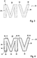
- the container base body 4 also has relief elements 20 which, in the exemplary embodiment shown, form the “Oberland MV” mark.
- Each letter is formed by a single relief element 20 which is raised in relation to the base surface 10, ie protrudes from the image plane by more than 0.5 mm, preferably from 2 mm to 3 mm.
- inverted relief elements 21 instead of relief elements 20, inverted relief elements 21 (cf. Fig. 7 ) be provided with such dimensions. It can also be provided that some of the letters are designed as relief elements 20 and some other of the letters are designed as inverted relief elements 21.
- the base area 10 of the transport container 2 can be smooth or also have a three-dimensional background structure.
- the three-dimensional background structure is less raised and / or recessed than the relief elements 20, for example with less than 1 mm, in particular with less than 0.5 mm raised and / or recessed features.
- the base area 10 can, for example, have a brushed, eroded, grained, etched, line-polished, highly polished and / or milled 3D background structure.
- the abutting edge 12 is also raised in relation to the base area 10.
- the abutting edge 12 is, for example, 2 mm to 3 mm raised with respect to the base surface 10 of the transport container 2.
- the abutting edge 12 preferably also protrudes further than the relief elements 20, so that the relief elements 20 of two identical transport containers 2 arranged next to one another do not touch when the side walls 8 of the transport containers 2 abut one another.
- the side wall 8 has an inmould film 22 which, in the illustrated embodiment, covers the entire base area 10 and all the relief elements 20.
- the transport container 2 can have one or more inmould films 22 which only partially cover the base area 10 of the side wall 8.
- the transport container 2 can also have one or more inmould films 22 which only cover some of the relief elements 20 or inverted relief elements 21 or which only partially cover them.
- the inmould film 22 extends not only over one side wall 8, but also over several side walls 8.
- the inmould film 22 can also be formed all the way around the side walls 8 of the transport container 2, i.e. cover all side walls 8.
- the inmould film 22 can alternatively also cover a corner area of the transport container 2, in particular one or two side walls 8.
- the inmould film 22 has a first region 24 assigned to the base area 10, which is here, for example, the region in which the inmould film 22 covers the entire base area 10.
- the inmould film has a second area 26 for each relief element 20, in which the inmould film 22 covers the corresponding relief element 20.
- Figure 2 shows an inmould film 22 according to an embodiment of the invention, this being designed, for example, according to its outer contour 28 such that its first area 24 does not cover the entire base area 10 of the side wall 8 (not shown here), but only part of it.
- Figure 3 shows the in Figure 2 Area A of the inmould film 22 shown in an enlarged illustration according to a first embodiment of the inmould film 22.
- Part of the inmould film 22 is shown with the first area 24 assigned to the base area 10, a second area 26 assigned to the relief element "M” and a second area 26 assigned to the relief element "V".
- a transition area 30 between the first area 24 and the second area 26 the inmould film 22 has a preconditioning 31 in the form of a perforation 32 which completely surrounds the two second areas 26.
- the transition region 30 can also be referred to below as an inner contour of the inmould film 22, and is also referred to with reference to FIG Figures 5 to 13 shown and explained in more detail.
- FIG 4 is an enlargement of the in Figure 2 Area A shown according to a further embodiment of the inmould film 22.
- the inmould film 22 has a first area 24 assigned to the base area 10 and two second areas 26 assigned to the relief elements 20.
- the inmould film 22 has a large number of preconditions 31 in the form of cuts 34, with a total of five cuts 34 being provided for the relief element "M” and for the Relief element "V" a total of three cuts 34.
- Preconditioning 31 shown can also be punched, punched or z. B. be disengagement.
- FIG. 11 shows an enlarged detailed illustration of the area B from FIG Figure 4 at a foot of the relief element "M".
- the first area 24 is connected to the second area 26 via the web 36, so that the inmould film 22 is in one piece.
- To the side of the web 36 are two preconditions 31, which are designed as cuts 34 as described.
- the transition area 30 between the first area 24 and the second area 26 is formed by the web 36 and the preconditions 31.
- the preconditions 31 give rise to the well-defined compensating recesses 23, which are described below with reference to Figures 6 and 7 are shown and described.
- the transition region 30 has a thickness d 1 .
- the web 36 has a web width d 2 .
- Figure 6 shows a sectional view through the in Figure 1 Line C - C shown, ie through the center of the relief element "M".
- a section through the container base body 4 and through the inmould film 22 arranged thereon is shown. The proportions are not shown true to scale in order to facilitate understanding.
- the inmould film 22 has a first area 24 which covers the base area 10 of the container base body 4.
- the inmould film 22 has a second area 26 which covers the relief element 20. Furthermore, the inmould film 22 comprises two transition areas 30 between the first area 24 and the second area 26.
- the first transition area 30 shown on the left has a well-defined compensating recess 23 which is designed as an opening 25.
- the opening 25 is for example the product of one of the with reference to the Figures 3 to 5 described preconditions 31 after the injection molding.
- the inmould film 22 has the web 36, which further connects the first area 24 with the second area 26 with one another.
- the relief element 20 has a height d 6 .
- the length of the web 36 that is to say the width d 1 of the transition region 30, essentially corresponds to the height d 6 of the relief element 20, apart from the distortion caused by the pressure during injection molding.
- the inmould film 22 comprises four layers, with a first printing layer 44 being at least partially arranged on the side 40 facing the container base body 4. Above the first printing layer 44 is a base film 46 which forms the second layer and which is at least partially covered with a second printing layer 48 which forms the third layer. On the side 42 of the inmould film 22 facing away from the container base body 4 there is a cover layer 50, which can be, for example, a coating and / or a lamination.
- FIG. 13 shows an alternative embodiment to that with reference to FIG Figure 1 and 6 described embodiment of the invention, the "M" being designed as an inverted relief element 21 here.
- the container body 4 comprises the Base 10 and the inverted relief element 21, which is recessed with respect to base 10 and forms the letter "M", for example.
- the depth of the inverted relief element is represented by d 7 .
- the inmould film 22 comprises, as with reference to FIG Figure 6 already described, the first area 24 and the second area 26, as well as corresponding transition areas 30, which connect the first and second areas 24, 26 to one another. In the transition area 30 shown on the left, the well-defined compensation recess 23 is formed by the opening 25 and the web 36 is located in the transition area 30 shown on the right.
- the inmould film 22 comprises, as with reference to FIG Figure 6 described, a four-layer structure, the side 40 facing the container base body 4 comprising a first printing layer 44 and the side 42 facing away from the container base body 4 the cover layer 50.
- Figure 8 shows a sectional view of part of an inmould film 22 showing the first area 24, the transition area 30 and the second area 26 before it was placed on the container body 4 (not shown here and below) and back-injected, ie an inmould film 22, the z. B. is still fed to the injection molding tool.
- the inmould film 22 has a preconditioning 31 designed as an area 52 with a reduced thickness.
- the area 52 with reduced thickness is formed here by punching, the in-mold film 22 not being divided into two parts by the punching, as in the case of punching, but having a film hinge 38, which is present here, for example, in the middle of the transition area 30 .
- the film hinge 38 is provided on the side 40 facing the container base 4.
- the film hinge 38 can be provided on the side 42 facing away from the container base body 4, the punching taking place from the corresponding side.
- the inmould film 22 includes those with reference to Figures 6 and 7 The layer sequence described with the first printing layer 44 facing the container base 4, followed by the base film 46, the second printing layer 48 and the cover layer 50 facing away from the container base 4.
- the inmould film 22 has a thickness d 3 in its second region 26 and in its first Area has a thickness d 4 , the thicknesses d 3 and d 4 here, for example and typically, being of the same design.
- Figure 9 shows an inmould film 22 according to an alternative embodiment, wherein as in FIG Figure 8 the first area 24, the transition area 30 and the second area 26 are shown.
- the inmould film 22 has a preconditioning 31 designed as an opening 54, which can be a cut 34 or a perforation 32, for example.
- Figure 10 shows an inmould film 22 according to an alternative embodiment, the inmould film 22 comprising three layers.
- the base film 46 is located on the side 40 of the inmould film 22 facing the container base body 4, this being covered by the second printing layer 48.
- the inmould film 22 is otherwise designed as described above and, in the exemplary embodiment shown, comprises the film hinge 38 in the transition region 30.
- Figure 11 shows a double film 64 with two in-mold films 22-1, 22-1 arranged one above the other, with as in FIG Figures 8 to 10 corresponding to the first area 24, the second area 26 and the transition area 30 are shown.
- the two inmould films 22-1, 22-2 lie flat on top of one another, with a first inmould film 22-1 facing the container base 4 and a second inmould film 22-2 facing away from the container base 4 (or will be ).
- Both inmould films 22 - 1, 22 - 2 have the preconditioning 31 in the transition area 30, this in turn comprising the film hinge 38, which is located on the side 40 facing the container base 4.
- Both in-mold films 22-1, 22-2 in the illustrated embodiment comprise the same four-layer structure, which with reference to the Figures 6 to 9 has been described.
- the second inmould film 22-2 is, however, shortened in the first region 24 and only partially rests there on the first inmould film 22-1.
- the inmould films 22-1, 22-2 thus have an overlap region 60 and, in the first region 24, an individual film region 62 which is formed only by the first inmould film 22-1.
- the double film 64 has a thickness d 8 and in the individual film region 62 a thickness d 9 .
- Figure 12 shows an alternative embodiment of a double film 64, which comprises two in-mold films 22-1, 22-2, the first in-mold film 22-1 one with reference to the Figures 6 to 9 is described four-layer inmould film 22 and wherein the second inmould film 22-2 one with reference to Figure 10 described three-layer inmould film 22 is.
- the double film 64 includes the film hinge 38 that forms the well-defined compensating recess 23.
- the second inmould film 58 does not cover the first inmould film 56 over its entire surface.
- the overlapping area 60 is only provided in a part of the second area 26, ie on a part of the relief element 20 or inverted relief element 21, and the individual film area 62 is present in the base area 10.
- FIG. 11 shows another embodiment of the double foil 64, wherein, as with reference to FIG Figure 12 described, the first inmould film 22-1 is designed as a four-layer inmould film 22 and the second inmould film 22-2 is designed as a three-layer inmould film 22.
- the well-defined compensating recess 23 is designed as a film hinge 38.
- the overlapping area 60 is only provided precisely in the second area 26, ie on the relief element 20 or inverted relief element 21, so that the individual film area 62 is present in the base area 10
- first inmould film 22-1 is matt and the second inmould film 22-2 has a high-gloss finish, or vice versa.
- inventions of the invention can also include double films 64, both inmould films 22-1, 22-2 being designed as three-layer inmould films 22 or the first inmould film 22-1 facing the container base 4 being a three-layer one Is in-mold film 22 and the second in-mold film 22-2 facing away from the container base body 4 is a four-layer in-mold film 22.
- Figure 14 shows an injection molding system 100 by means of which a transport container according to the invention can be produced.
- the injection molding system 100 comprises an injection molding tool 110, in which an inmould film 22 is back-molded by the plastic forming the container base body.
- the injection molding tool 110 is coupled to a first vacuum system 112, which is set up to apply one or more vacuums to a tool jaw (not shown) of the injection molding tool 110 in order to used inmould film 22 to hold in position as a whole or with island areas.
- the injection molding system 100 also includes a robot device 120 with here, for example, a robot arm 122 which has a manipulating head 126 that can be freely positioned in space by means of joints 130.
- a camera 124 is attached to the robot device 120, which is set up with appropriate software to recognize imprints 29 and preconditions 31, such as outer contours 28 of the inmould films 22, or to recognize the position of the inmould film 22.
- the manipulating head 126 also comprises a suction device 128 which is connected to a second vacuum system 132 in order to generate vacuum along vacuum edges.
- a suction device 128 By means of the suction device 128, the manipulating head 126 can separate the inmould films 22 and insert them into the tool jaw of the injection molding tool 110 for subsequent back injection.
- the inmould foils 22 are initially in a wound form on a roll 136, i. are fed to the injection molding tool 110 in the illustrated embodiment as roll goods.
- the feed device 134 unrolls the roller 136.
- it comprises a series of conveyor rollers 138, this being only one of many possibilities that are familiar to the person skilled in the art.
- a pair of rollers is also shown with two intermeshing structured rollers 140 through which the inmould foils 22 are guided and which produce a structuring on the inmould foils 22 which corresponds to a matt effect.
- the injection molding tool 110, the robot device 120, the vacuum systems 112, 132 and the feed device 134 are connected to a central control 150, which coordinates the individual processes with one another.
- the central control 150 can effect a precise transfer and positioning of the inmould film 22 in the injection molding tool 110.
Description
Die Erfindung betrifft einen Transportbehälter, insbesondere einen Flaschenkasten zur Aufnahme von Getränkeflaschen oder Flaschengebinden, sowie ein Verfahren zur Herstellung eines derartigen Transportbehälters.The invention relates to a transport container, in particular a bottle crate for receiving beverage bottles or bottle containers, and to a method for producing such a transport container.
Aus
Die in der
Demgegenüber liegt der Erfindung die Aufgabe zu Grunde, einen Transportbehälter und ein Verfahren zu dessen Herstellung zu schaffen, welche die Nachteile des Stands der Technik überwinden. Insbesondere ist es eine Aufgabe der Erfindung, einen Transportbehälter, insbesondere einen Flaschenkasten mit einer Inmould-Folie bereitzustellen, welcher neben den vorteilhaften Eigenschaften zur Vermeidung von oberflächlichen Defekten einen neuen und einprägsamen Gesamteindruck aufweist, durch welchen er sich für die beteiligten Verkehrskreise aus der Vielzahl der bereits vorhandenen Transportbehälter abhebt.In contrast, the invention is based on the object of creating a transport container and a method for its production which overcome the disadvantages of the prior art. In particular, it is an object of the invention to provide a transport container, in particular a To provide bottle crates with an inmould film which, in addition to the advantageous properties for avoiding superficial defects, has a new and memorable overall impression, through which it stands out from the multitude of already existing transport containers for the public involved.
Die Aufgabe wird gelöst durch einen Transportbehälter sowie durch ein Verfahren zur Herstellung eines Transportbehälters mit den Merkmalen der unabhängigen Ansprüche. Vorteilhafte Weiterbildungen der Erfindung sind in den Unteransprüchen angegeben.The object is achieved by a transport container and by a method for producing a transport container with the features of the independent claims. Advantageous further developments of the invention are specified in the subclaims.
Bei einem erfindungsgemäßen Transportbehälter, insbesondere Flaschenkasten zur Aufnahme von Getränkeflaschen oder Flaschengebinden, umfassend einen Behältergrundkörper, der einen Boden und vier Seitenwände aufweist, ist vorgesehen, dass zumindest eine der Seitenwände eine Grundfläche und zumindest ein bezüglich der Grundfläche erhaben ausgebildetes Reliefelement oder zumindest ein bezüglich der Grundfläche vertieft ausgebildetes invertiertes Reliefelement aufweist, wobei die Seitenwand zumindest eine zumindest teilweise jeweils die Grundfläche und das Reliefelement oder das invertierte Reliefelement bedeckende Inmould-Folie aufweist, und wobei die Inmould-Folie einen der Grundfläche zugeordneten ersten Bereich aufweist und einen dem Reliefelement oder invertierten Reliefelement zugeordneten zweiten Bereich. Weiterhin ist vorgesehen, dass die Inmould-Folie in einem Übergangsbereich vom ersten Bereich zum zweiten Bereich zumindest eine wohldefinierte Ausgleichsaussparung aufweist.In a transport container according to the invention, in particular a bottle crate for receiving beverage bottles or bottle containers, comprising a container base body which has a bottom and four side walls, it is provided that at least one of the side walls has a base area and at least one relief element raised with respect to the base area or at least one with respect to the The base area has a recessed inverted relief element, the side wall having at least one inmould film that at least partially covers the base area and the relief element or the inverted relief element, and wherein the inmould film has a first area assigned to the base area and a relief element or an inverted relief element assigned second area. It is also provided that the inmould film has at least one well-defined compensating recess in a transition area from the first area to the second area.
"Wohldefiniert" bezeichnet entweder die Form oder die Größe oder auch Form und Größe der Ausgleichsaussparung. Die wohldefinierte Ausgleichsaussparung der Inmould-Folie ist insbesondere dahingehend wohldefiniert, dass sie in einem Vorverarbeitungsschritt der Inmould-Folie vor dem Hinterspritzen der Inmould-Folie im Spritzgusswerkzeug in Form und Größe festgelegt wird. Die wohldefinierte Ausgleichsaussparung ist also durch eine Vorkonditionierung der Inmould-Folie angelegt. Die Vorkonditionierung der Inmould-Folie stellt sicher, dass sich nach dem Spritzgießen die wohldefinierte Ausgleichsaussparung in gewünschter Form und Größe an der gewünschten Stelle befindet, nämlich im Übergangsbereich vom ersten Bereich zum zweiten Bereich der Inmould-Folie."Well-defined" means either the shape or the size or also the shape and size of the compensation recess. The well-defined compensation recess of the in-mold film is well-defined in particular to the effect that it is determined in shape and size in a preprocessing step of the in-mold film before the in-mold film is back-injected in the injection molding tool. The well-defined compensation recess is therefore created by preconditioning the inmould film. The preconditioning of the inmould film ensures that the well-defined compensation recess is in The desired shape and size is located in the desired location, namely in the transition area from the first area to the second area of the inmould film.
Die Vorkonditionierung bewirkt dabei vorteilhaft, dass während des Spritzgießens im Übergangsbereich vom ersten zum zweiten Bereich der Druck auf die Inmould-Folie verringert wird, sodass gezielt einem undefinierten Reißen der Inmould-Folie und einem damit verbundenen Verzerren der Bedruckungen im Bereich des Reliefelements oder des invertierten Reliefelements entgegengewirkt wird. Der erfindungsgemäße Transportbehälter erhält hierdurch einen gefälligeren, da wohldefinierten optischen Eindruck.The preconditioning has the advantageous effect that during injection molding in the transition area from the first to the second area the pressure on the in-mold film is reduced, so that an undefined tearing of the in-mold film and an associated distortion of the printing in the area of the relief element or the inverted element are targeted Relief elements is counteracted. This gives the transport container according to the invention a more pleasing, since it is well-defined, visual impression.
Gemäß einer Ausführungsform ist die wohldefinierte Aussparung durch einen Bereich mit verringerter Foliendicke ausgebildet. Bei der Zuführung der Inmould-Folie zum Spritzgusselement ist hierzu eine Vorkonditionierung in Form eines Bereichs mit verringerter Foliendicke angelegt, oder sie wird durch eine Manipulation beispielsweise durch eine Robotervorrichtung vor dem Einlegen in das Spritzgusswerkzeug der Inmould-Folie beigefügt. Während des Spritzgießens wird der Bereich mit verringerter Foliendicke gedehnt, sodass nach dem Spritzguss weiterhin ein Bereich mit verringerter Foliendicke vorliegt, ohne dass in diesem Bereich die Inmould-Folie gerissen ist.According to one embodiment, the well-defined recess is formed by an area with a reduced film thickness. When the in-mold film is fed to the injection molding element, preconditioning is applied in the form of an area with reduced film thickness, or it is added to the in-mold film by manipulation, for example by a robot device, before it is inserted into the injection molding tool. During injection molding, the area with reduced film thickness is stretched, so that after injection molding there is still an area with reduced film thickness without the in-mold film tearing in this area.
Gemäß einer alternativen Ausführungsform der Erfindung ist die wohldefinierte Ausgleichsaussparung durch eine Öffnung in der Inmould-Folie ausgebildet. Die Öffnung in der Inmould-Folie kann zum Beispiel aus einer bereits bei der Zuführung der Inmould-Folie zum Spritzgusselement als entsprechende Vorkonditionierung der Inmould-Folie vorhandenen Öffnung, oder durch Manipulation beispielsweise durch eine Robotervorrichtung vor dem Einlegen in das Spritzgusswerkzeug der Inmould-Folie beigefügten Öffnung entstanden sein. Alternativ kann vorgesehen sein, dass die Öffnung durch ein wohldefiniertes Reißen einer Vorkonditionierung in Form eines Bereichs mit verringerter Foliendicke entsteht.According to an alternative embodiment of the invention, the well-defined compensating recess is formed by an opening in the inmould film. The opening in the in-mold film can be added to the in-mold film, for example, from an opening already present when the in-mold film is fed to the injection molding element as a corresponding preconditioning of the in-mold film, or by manipulation, for example by a robot device, before it is inserted into the injection molding tool Opening. Alternatively, it can be provided that the opening is created by a well-defined tearing of a preconditioning in the form of an area with a reduced film thickness.
Für den Fall, dass die Öffnung in der Inmould-Folie bereits beim Einlegen der Inmould-Folie in das Spritzgusswerkzeug als Vorkonditionierung vorhanden ist, kann sich die Öffnung während des Spritzgießens aufgrund der auf die Folie wirkenden Drücke vergrößern oder mit anderen Öffnungen verbinden, wobei dieses ein Vorgang ist, der zu einer wohldefinierten Ausgleichsaussparung im Sinne der Erfindung führt. Vorteilhaft wird dabei ausgenutzt, dass die Öffnung beispielsweise in eine Richtung senkrecht zum Zug reißen wird, oder in eine Richtung reißen wird, in der sich eine nahegelegene weitere Öffnung befindet.In the event that the opening in the in-mold film is already present as preconditioning when the in-mold film is inserted into the injection molding tool, the opening can enlarge during injection molding due to the pressures acting on the film or connect to other openings, whereby this is a process that leads to a well-defined compensation recess within the meaning of the invention. Advantageously, use is made of the fact that the opening for example, will tear in a direction perpendicular to the train, or will tear in a direction in which there is another opening nearby.
Die Folie kann also während des Spritzgießens reißen, wobei sich das Reißen vorteilhaft auf den durch die Vorkonditionierung definierten Bereich beschränkt, d. h. räumlich im Bereich der Vorkonditionierung erfolgt und durch diese bestimmt wird.The film can therefore tear during injection molding, the tearing being advantageously restricted to the area defined by the preconditioning, i.e. H. takes place spatially in the area of the preconditioning and is determined by this.
Die Vorkonditionierung in Form des Bereichs mit verringerter Foliendicke kann beispielsweise durch eine Anstanzung oder durch eine Ausspanung gebildet sein. Insbesondere kann sie einen Filmscharnierbereich umfassen.The preconditioning in the form of the area with reduced film thickness can be formed, for example, by punching or by chipping. In particular, it can comprise a film hinge area.
Die Vorkonditionierung in Form der Öffnung auch kann durch eine Stanzung gebildet sein. Alternativ kann die Vorkonditionierung in Form der Öffnung durch eine Perforation gebildet sein, wobei hiermit eine Vielzahl von Löchern entlang einer vorgegebenen Linie gemeint ist. Weiter alternativ kann die Vorkonditionierung durch einen Schnitt gebildet sein.The preconditioning in the form of the opening can also be formed by punching. Alternatively, the preconditioning can be formed in the form of the opening by a perforation, which means a multiplicity of holes along a predetermined line. As a further alternative, the preconditioning can be formed by a cut.
Für den Fall, dass die Inmould-Folie das Reliefelement oder das invertierte Reliefelement vollständig bedeckt, kann vorgesehen sein, dass die wohldefinierte Ausgleichsaussparung das Reliefelement oder das invertierte Reliefelement vollständig umgibt. Alternativ kann vorgesehen sein, dass die wohldefinierte Ausgleichsaussparung das Reliefelement oder das invertierte Reliefelement teilweise umgibt.In the event that the inmould film completely covers the relief element or the inverted relief element, it can be provided that the well-defined compensation recess completely surrounds the relief element or the inverted relief element. Alternatively, it can be provided that the well-defined compensation recess partially surrounds the relief element or the inverted relief element.
Gemäß einer Ausführungsform der Erfindung weist die Inmould-Folie im Übergangsbereich vom ersten Bereich zum zweiten Bereich Stege auf, die den ersten Bereich und den zweiten Bereich miteinander verbinden. Durch die Stege wird der erste Bereich der Inmould-Folie mit dem zweiten Bereich der Inmould-Folie vorteilhaft derart miteinander verbunden, dass das Druckbild der Inmould-Folie, welches das Reliefelement oder invertierte Reliefelement überdeckt, auf diesem gezielt platziert werden kann, ohne dass es zu einem ungewollten seitlichen Versatz kommt. Die Stege sind bevorzugt von 50 µm bis 1 mm breit ausgebildet. Hierdurch wird der Eindruck, der sich durch das Vorhandensein der Stege auf den Übergangsbereich ergibt, möglichst wenig geprägt.According to one embodiment of the invention, the inmould film has webs in the transition area from the first area to the second area which connect the first area and the second area to one another. By means of the webs, the first area of the in-mold film is advantageously connected to the second area of the in-mold film in such a way that the print image of the in-mold film, which covers the relief element or inverted relief element, can be placed on it in a targeted manner without it comes to an unwanted lateral offset. The webs are preferably designed from 50 μm to 1 mm wide. As a result, the impression that results from the presence of the webs on the transition area is shaped as little as possible.
Für den Fall, dass eine Perforation vorgesehen ist, sind der erste und der zweite Bereich an einer Vielzahl von Stellen, beispielsweise an mehr als zwanzig Stellen, miteinander verbunden.In the event that a perforation is provided, the first and second areas are connected to one another at a large number of locations, for example at more than twenty locations.
Alternativ ist vorgesehen, dass der erste und zweite Bereich an weniger als zehn Stellen, weniger als fünf Stellen, an vier, drei, insbesondere an zwei Stellen, an einer Stelle oder an keiner Stelle miteinander verbunden sind. Hierdurch wird vorteilhaft der optische Eindruck des Übergangsbereiches, in welchem also das Reliefelement sich erhebt bzw. das invertierte Reliefelement sich versenkt, an nur sehr wenigen Stellen oder gar an keiner Stelle durch die Stege beeinflusst.Alternatively, it is provided that the first and second areas are connected to one another at fewer than ten points, fewer than five points, at four, three, in particular at two points, at one point or at no point. In this way, the visual impression of the transition area, in which the relief element rises or the inverted relief element is sunk, is advantageously influenced by the webs at only a few points or at no point at all.
Vorteilhaft ist das Reliefelement oder das invertierte Reliefelement mehr als 0,5 mm, bevorzugt mehr als 1 mm, weiter bevorzugt mehr als 1,5 mm, noch weiter bevorzugt mehr als 2 mm und insbesondere von 2 mm bis 5 mm, von 2 mm bis 4 mm oder von 2 mm bis 3 mm gegenüber der Grundfläche erhaben oder vertieft ausgebildet. Durch die erfindungsgemäßen wohldefinierten Ausgleichsaussparungen kann das Reliefelement oder das invertierte Reliefelement ein wesentlich stärkeres Profil, d.h. eine größere maximale Versatzhöhe aufweisen als bei bisherigen Inmould-Folien, ohne dass der optische Eindruck des Druckbildes auf der Inmould-Folie in den zweiten Bereichen, in denen die Inmould-Folie die Reliefelemente bzw. invertierten Reliefelemente überdeckt, beeinträchtigt wird. Das Reliefelement oder invertierte Reliefelement kann z. B. einen Buchstaben und/oder ein Symbol, ein Logo, eine Marke oder auch einen Werbeschriftzug umfassen.The relief element or the inverted relief element is advantageously more than 0.5 mm, preferably more than 1 mm, more preferably more than 1.5 mm, even more preferably more than 2 mm and in particular from 2 mm to 5 mm, from 2 mm to 4 mm or from 2 mm to 3 mm raised or recessed from the base area. By means of the well-defined compensation recesses according to the invention, the relief element or the inverted relief element can have a significantly stronger profile, i.e. have a greater maximum offset than previous in-mold films, without the visual impression of the print image on the in-mold film in the second areas, in which the in-mold film covers the relief elements or inverted relief elements, is impaired. The relief element or inverted relief element can, for. B. a letter and / or a symbol, a logo, a brand or even an advertising lettering.
Für den Fall, dass der Transportbehälter einen Stoßrand oder Stoßleisten aufweist, ist bevorzugt vorgesehen, dass die erhaben ausgebildeten Reliefelemente im Vergleich zu dem Stoßrand oder den Stoßleisten weniger stark erhaben gegenüber der Grundfläche der Seitenwand ausgebildet sind.In the event that the transport container has a bumper edge or bumper strips, it is preferably provided that the raised relief elements are less raised than the base of the side wall compared to the bumper edge or bumper strips.
Im typischen Fall sind eine Vielzahl oder sämtliche Reliefelemente und/oder invertierten Reliefelemente, die auf dem Transportbehälter vorgesehen sind, mit einer oder mehreren Inmould-Folien bedeckt. In diesem Fall können vorteilhaft entlang den Konturen sämtlicher Reliefelemente oder invertierter Reliefelemente eine Vielzahl von Vorkonditionierungen vorgesehen sein, sodass die Inmould-Folie in den ersten Bereichen, in welchen sie die Grundfläche überdeckt, und in den zweiten Bereichen, in welchen sie die Reliefelemente oder invertierten Reliefelemente überdeckt, nicht unkontrolliert reißt.Typically, a large number or all of the relief elements and / or inverted relief elements that are provided on the transport container are covered with one or more inmould films. In this case, a large number of preconditions can advantageously be provided along the contours of all relief elements or inverted relief elements so that the inmould film in the first areas in which it covers the base area and in the second areas in which it inverts the relief elements or Relief elements covered, not cracking uncontrollably.
Gemäß einer Ausführungsform der Erfindung weist die Inmould-Folie eine Lackschicht auf. Bei lackierten Inmould-Folien, die vor dem Hinterspritzen bereits eine Lackschicht aufweisen, ist es bisher nicht gelungen, diese auf Seitenwänden mit Reliefelementen oder invertierten Reliefelementen anzuordnen. Wohldefinierte Ausgleichsaussparungen in den Übergangsbereichen verhindern vorteilhaft, dass die Lackschicht beim Hinterspritzen platzt oder reißt, sodass mit der vorliegenden Erfindung völlig neue Gestaltungsmöglichkeiten des Transportbehälters vorliegen.According to one embodiment of the invention, the inmould film has a lacquer layer. In the case of lacquered in-mold films, which already have a lacquer layer before back-molding, it has not yet been possible to arrange these on side walls with relief elements or inverted relief elements. Well-defined compensation recesses in the transition areas advantageously prevent the lacquer layer from bursting or tearing during back-molding, so that the present invention provides completely new design options for the transport container.
Gemäß einer alternativen Ausführungsform weist die Inmould-Folie eine Kaschierung auf. Bei kaschierten Inmould-Folien, die vor dem Hinterspritzen bereits eine Kaschierung aufweisen, ist bisher nicht gelungen, diese auf Seitenwänden mit Reliefelementen anzuordnen, welche mehr als 2 mm erhaben, bzw. mit invertierten Reliefelementen, welche mehr als 2 mm vertieft ausgebildet sind. Wohldefinierte Ausgleichsaussparungen in den Übergangsbereichen verhindern vorteilhaft, dass es beim Spritzgussvorgang zu einem Bruch der Kaschierung kommt, sodass mit der vorliegenden Erfindung völlig neue optische Eindrücke des Transportbehälters ermöglicht werden.According to an alternative embodiment, the inmould film has a lamination. In the case of laminated in-mold films that already have a lamination before back-injection, it has not been possible to arrange them on side walls with relief elements that are raised by more than 2 mm or with inverted relief elements that are recessed by more than 2 mm. Well-defined compensation recesses in the transition areas advantageously prevent the lamination from breaking during the injection molding process, so that the present invention enables completely new visual impressions of the transport container.
Die Inmould-Folie kann teilweise oder vollständig einen Matteffekt aufweisen. Es kann insbesondere auch vorgesehen sein, dass die Inmould-Folie nur im ersten Bereich oder nur im zweiten Bereich einen Matteffekt aufweist. Insbesondere kann vorgesehen sein, dass die Inmould-Folie im ersten Bereich matt ausgeführt ist und im zweiten Bereich hochglänzend oder umgekehrt.The inmould film can partially or completely have a matt effect. In particular, it can also be provided that the inmould film has a matt effect only in the first area or only in the second area. In particular, it can be provided that the inmould film is matt in the first area and high-gloss in the second area or vice versa.
Ein Matteffekt der Inmould-Folie kann beispielsweise durch eine Strukturierung erzeugt werden, welche im Spritzvorgang durch Einprägung einer auf der Werkzeugbacke befindlichen Struktur herbeigeführt wird. Strukturen, deren Körnung in etwa einem 250er Korn mit Strukturgrößen von 10 µm bis 80 µm entspricht, führen dabei zu einer matt wirkenden Fläche der Inmould-Folie. Extrem glatte Abschnitte der Grundfläche hingegen erzeugen eine Glanzoptik in der Inmould-Folie. Geeignete auf der Werkzeugbacke befindliche Strukturen sind beispielsweise Erodierungen, insbesondere Erodierungen gemäß VDI-Normen wie z. B. VDI 36. Alternative geeignete auf der Werkzeugbacke befindliche Strukturen können gebürstete, genarbte, geätzte, und/oder gefräste Strukturen in entsprechender Korngröße umfassen.A matt effect of the in-mold film can be produced, for example, by a structuring which is brought about in the injection molding process by embossing a structure on the tool jaw. Structures whose grain size corresponds roughly to a 250 grain with structure sizes of 10 µm to 80 µm lead to a matt-looking surface of the inmould film. Extremely smooth sections of the base, on the other hand, create a glossy look in the inmould film. Suitable structures located on the tool jaw are, for example, erosion, in particular erosion according to VDI standards such as e.g. B. VDI 36. Alternative suitable structures located on the tool jaw can include brushed, grained, etched, and / or milled structures in a corresponding grain size.
Der Matteffekt kann sich auch bereits vor dem Spritzguss inhärent in oder auf der Inmould-Folie befinden. Der Matteffekt kann z. B. durch Verwenden einer transluzenten Inmould-Folie mit strukturierter Oberfläche entstehen und/oder durch einen Farbaufdruck oder Auftrag eines Lacks. Die Strukturierung der Oberfläche kann beispielsweise mittels Durchführen der Inmould-Folie durch ein Walzenpaar erzeugt werden, wobei zwei ineinandergreifende Druck ausübende Walzen mit strukturierter Oberfläche die transluzente Folie von beiden Seiten verformen und dadurch eine doppelte Tiefe (z.B. -0,5 mm) bzw. Erhöhung (z.B. + 0,5 mm) ohne eine Überdehnung der Folie erzeugen. In vorteilhaften Ausführungsformen kann die Walze auch derart gestaltet sein, dass strukturierte und unstrukturierte Flächen nebeneinander liegen.The matt effect can also be inherent in or on the inmould film before injection molding. The matt effect can, for. B. by using a translucent inmould film with a structured surface and / or by color printing or application of a lacquer. The structuring of the surface can be created, for example, by passing the inmould film through a pair of rollers, with two interlocking pressure rollers with a structured surface deforming the translucent film from both sides and thereby doubling the depth (e.g. -0.5 mm) or elevation (e.g. + 0.5 mm) without overstretching the film. In advantageous embodiments, the roller can also be designed in such a way that structured and unstructured surfaces lie next to one another.
Die Grundfläche kann glatt ausgeführt sein oder eine insbesondere gebürstete, erodierte, genarbte, geätzte, strichpolierte, hochglanzpolierte und/oder gefräste 3D-Hintergrundstruktur aufweisen. Die 3D-Hintergrundstruktur kann beispielsweise weniger als 1 mm, insbesondere als 0,5 mm erhaben und/oder vertieft ausgebildete Merkmale umfassen. Die 3D-Hintergrundstruktur kann dabei insbesondere flächenartige Bestandteile umfasst, welche z. B. natürlichen und/oder industriellen Oberflächenstrukturen nachempfunden sind, beispielsweise Holz-Maserungsstrukturen, Stein- oder Granitmuster, Riffelblechoberflächen oder dergleichen.The base surface can be made smooth or in particular have a brushed, eroded, grained, etched, line-polished, high-gloss polished and / or milled 3D background structure. The 3D background structure can for example include features that are raised and / or recessed less than 1 mm, in particular 0.5 mm. The 3D background structure can in particular include planar components, which z. B. natural and / or industrial surface structures are modeled, for example wood grain structures, stone or granite patterns, checkered plate surfaces or the like.
Es kann vorgesehen sein, dass jede Seite des Transportbehälters mit mindestens einer Inmould-Folie versehen ist. Auch Inmould-Folien, welche um eine Kante oder Ecke des Transportbehälters herum verlaufen, sind möglich.It can be provided that each side of the transport container is provided with at least one inmould film. In-mold foils that run around an edge or corner of the transport container are also possible.
Gemäß einer Ausführungsform der Erfindung ist vorgesehen, dass die Seitenwand zwei zumindest teilweise übereinander angeordnete zumindest teilweise jeweils die Grundfläche und das Reliefelement oder das invertierte Reliefelement bedeckende Inmould-Folien aufweist, wobei eine oder beide der Inmould-Folien im Übergangsbereich vom ersten Bereich zum zweiten Bereich zumindest eine wohldefinierte Ausgleichsaussparung aufweisen. Dabei kann vorgesehen sein, dass die Seitenwand zwei vollflächig aufeinander liegende Inmould-Folien aufweist oder zwei Inmould-Folien, welche sich nur teilweise überlappen.According to one embodiment of the invention it is provided that the side wall has two at least partially one above the other at least partially each covering the base and the relief element or the inverted relief element covering inmould films, one or both of the inmould films in the transition area from the first area to the second area have at least one well-defined compensation recess. It can be provided that the side wall has two in-mold foils lying on top of one another over the entire surface or two in-mold foils which only partially overlap.
Gemäß einer Ausführungsform weisen beide Inmould-Folien wohldefinierte Ausgleichsaussparungen auf, wobei die wohldefinierten Ausgleichsaussparungen übereinander angeordnet sind.According to one embodiment, the two inmould films have well-defined compensation cutouts, the well-defined compensation cutouts being arranged one above the other.
Insbesondere kann vorgesehen sein, dass eine oder beide Inmould-Folien eine Kaschierung oder Lackierung aufweisen und wohldefinierte Ausgleichsaussparungen aufweisen, um eine Beeinträchtigung der Lackschicht oder der Kaschierung zu verhindern.In particular, it can be provided that one or both inmould films have a lamination or coating and have well-defined compensation recesses in order to prevent impairment of the lacquer layer or the lamination.
Vorteilhaft ist es mit den Maßnahmen der Erfindung möglich, zwei Inmould-Folien übereinander zu platzieren, wobei diese zum Beispiel auch unterschiedlich gestaltet sein können. Zum Beispiel kann vorgesehen sein, dass eine der Inmould-Folien matt und die andere der Inmould-Folien hochglänzend ausgeführt ist.With the measures of the invention, it is advantageously possible to place two inmould films on top of one another, whereby these can also be designed differently, for example. For example, it can be provided that one of the inmould foils is matt and the other of the inmould foils is high-gloss.
Erfindungsgemäß ist auch eine Inmould-Folie zur Verwendung in einem zuvor beschriebenen Transportbehälter vorgesehen, wobei die Inmould-Folie zumindest eine Vorkonditionierung in einem Übergangsbereich vom ersten Bereich zum zweiten Bereich aufweist.According to the invention, an inmould film is also provided for use in a previously described transport container, the inmould film having at least one preconditioning in a transition area from the first area to the second area.
Die Inmould-Folie weist beispielsweise eine Dicke von 5 µm bis 190 µm auf. Insbesondere kann die Inmould-Folie eine Dicke von 60 µM bis 110 µm aufweisen.The inmould film has a thickness of 5 μm to 190 μm, for example. In particular, the inmould film can have a thickness of 60 μm to 110 μm.
Als Inmould-Folie kann insbesondere eine PE-Folie (Polyethylenfolie), PP-Folie (Polypropylenfolie) oder eine PET-Folie (Polyethylentherephthalat-Folie) als eine Grundfolie zum Einsatz kommen, welche einseitig oder beidseitig bedruckt sein kann, um eine Farbe und/oder Information in gewünschter Darstellung zu erhalten. Die Bedruckung der Inmould-Folie kann beispielsweise mit einem Offsetdruck und/oder mit einem Flexodruck und/oder mit einem Tiefdruck und/oder mit einem Digitaldruck und/oder mit einem Siebdruck erfolgen. Bei einem Offsetdruck kann vorgesehen sein, nur den Bereich mit einem Grundweiß-Farbdruck zu versehen, an dem sich gedruckte Information, z. B. Buchstaben oder Logos befindet.In particular, a PE film (polyethylene film), PP film (polypropylene film) or a PET film (polyethylene terephthalate film) can be used as an in-mold film as a base film, which can be printed on one or both sides to allow for a color and / or to receive information in the desired representation. The in-mold film can be printed, for example, with offset printing and / or with flexographic printing and / or with gravure printing and / or with digital printing and / or with screen printing. In the case of offset printing, provision can be made for only the area to be provided with a basic white color print on which printed information, e.g. B. letters or logos is located.
In einer Ausführungsform ist eine Inmould-Folie vorgesehen, bei welcher die Grundfolie auf der dem Behältergrundkörper zugewandten Seite eine erste Bedruckung aufweist und auf der dem Behältergrundkörper abgewandten Seite eine zweite Bedruckung aufweist. Insbesondere kann vorgesehen sein, dass Form und Farbe der ersten Bedruckung und der zweiten Bedruckung einander entsprechen. Für den Fall, dass die Inmould-Folie oberflächlich angekratzt wird, dass also die Kaschierung der Folie und beispielsweise die zweite Druckschicht beeinträchtigt werden, kann die erste Druckschicht den optischen Effekt vorteilhaft aufrechterhalten, sodass dem Verbraucher der Defekt nicht auffällt.In one embodiment, an inmould film is provided in which the base film has a first print on the side facing the container base body and has a second print on the side facing away from the container base body. In particular, it can be provided that the shape and color of the first printing and the second printing correspond to one another. In the event that the surface of the inmould film is scratched, that is, the lamination of the film and, for example, the second printing layer are adversely affected, the first printing layer can advantageously maintain the optical effect so that the consumer does not notice the defect.
Gemäß einer Ausführungsform ist die Grundfolie der Inmould-Folie transluzent in der Farbe des Behältergrundkörpers eingefärbt. Weiterhin ist die Grundfolie der Inmould-Folie vorzugsweise mit Wärme- und Lichtstabilisatoren (HALS-Stabilisatoren) ausgerüstet.According to one embodiment, the base film of the inmould film is colored translucent in the color of the container base body. Furthermore, the base film of the inmould film is preferably equipped with heat and light stabilizers (HALS stabilizers).
Auf der Grundfolie kann sich inhärent ein Matteffekt befinden. Der Matteffekt kann z. B. durch eine transluzente Inmouldfolie mit strukturierter Oberfläche erzeugt sein und/oder durch einen Farbaufdruck oder Auftrag eines Lacks. Die strukturierte Oberfläche kann beispielsweise mittels Durchführen der Grundfolie oder Inmould-Folie durch ein Walzenpaar erzeugt werden, wobei zwei ineinandergreifende Druck ausübende Walzen mit strukturierter Oberfläche die transluzente Folie von beiden Seiten verformen und dadurch eine doppelte Tiefe (z.B. -0,5 mm) bzw. Erhöhung (z.B. + 0,5 mm) ohne eine Überdehnung der Folie erzeugen. In vorteilhaften Ausführungsformen kann die Walze auch derart gestaltet sein, dass strukturierte und unstrukturierte Flächen nebeneinander liegen.There can be an inherent matt effect on the base film. The matt effect can, for. B. be generated by a translucent inmould film with a structured surface and / or by a color print or application of a lacquer. The structured surface can be produced, for example, by passing the base film or in-mold film through a pair of rollers, with two interlocking rollers with a structured surface deforming the translucent film from both sides and thereby doubling the depth (e.g. -0.5 mm) or Create an increase (e.g. + 0.5 mm) without overstretching the film. In advantageous embodiments, the roller can also be designed in such a way that structured and unstructured surfaces lie next to one another.
Die PE-, PP-oder PET-Grundfolie ist in einer vorteilhaften Ausführungsform mit einer Kaschierung oder mit einer Schutzlackschicht versehen. Auch laminierte Inmould-Folien, bei welchen die Grundfolie in eine Art Hülle aufgenommen ist, sind möglich. Derartige Kaschierungen und auch Schutzlacke helfen, die Druckschichten der Grund-Folie gegen Beschädigungen, beispielsweise durch vorbeikratzende Bestandteile einer Transportvorrichtung, durch Stapelung und Palettierung mit anderen Transportbehältern oder im alltäglichen Gebrauch zu schützen. Unter einer kaschierten Folie wird eine Folie verstanden, bei welcher die Grundfolie mit einer Kunststoff-Schutzschicht überzogen ist die ggf. noch eine haftvermittelnde Unterseite aufweisen kann. Insbesondere kann die Kaschierung durch eine PET-Klarsichtfolie realisiert sein. Die Kaschierung kann alternativ auch durch eine PP-Folie erfolgen. Insbesondere kann eine transparente Folie vorgesehen sein. Bei Ausführungsformen, in denen ausschließlich aus PE oder PP hergestellte IML-Folien eingesetzt werden, ist darüber hinaus vorteilhaft ein Recycling des Transportbehälters ohne sogenanntes downcycling möglich. In einigen Ausführungsformen kann die Kaschierung der Inmould-Folie außerdem mit Wärme- und Lichtstabilisatoren (HALS-Stabilisatoren) ausgerüstet sein. Die Kaschierung oder die Schutzlackschicht können ebenfalls bedruckt sein.In an advantageous embodiment, the PE, PP or PET base film is provided with a lamination or with a protective lacquer layer. Laminated in-mold films, in which the base film is accommodated in a kind of envelope, are also possible. Laminations of this type and also protective varnishes help to protect the printed layers of the base film against damage, for example from components of a transport device scratching past, from stacking and palletizing with other transport containers or in everyday use. A laminated film is understood to mean a film in which the base film is covered with a plastic protective layer, which can optionally also have an adhesion-promoting underside. In particular, the lamination can be implemented using a transparent PET film. Alternatively, the lamination can also be done with a PP film. In particular, a transparent film can be provided. In the case of embodiments in which IML films made exclusively from PE or PP are used, recycling of the transport container is also advantageously possible without so-called downcycling. In some embodiments, the lamination of the in-mold film can also be equipped with heat and light stabilizers (HALS stabilizers). The lamination or the protective lacquer layer can also be printed.
Erfindungsgemäß ist außerdem ein Verfahren zur Herstellung eines zuvor beschriebenen Transportbehälters vorgesehen, mit den folgenden Schritten:
- a) Zuführen einer Inmould-Folie zu einem Spritzgusswerkzeug;
- b) Einlegen der Inmould-Folie in einer Werkzeugbacke des Spritzgusswerkzeugs derart, dass der erste Bereich der Inmould-Folie einem der Grundfläche entsprechenden Werkzeugbackenabschnitt zugeordnet wird und dass der zweite Bereich der Inmould-Folie einem dem Reliefelement oder dem invertierten Reliefelement entsprechenden Werkzeugbackenabschnitt zugeordnet wird;
- c) Festhalten der Inmould-Folie in der Position und
- d) Hinterspritzen der Inmould-Folie mit einem den Behältergrundkörper bildenden Kunststoffmaterial, sodass der erste Bereich der Inmould-Folie mit der Grundfläche und der zweite Bereich der Inmould-Folie mit dem Reliefelement oder dem invertierten Reliefelement verbunden werden.
- a) feeding an in-mold film to an injection molding tool;
- b) inserting the inmould film in a tool jaw of the injection molding tool such that the first region of the inmould film is assigned to a tool jaw section corresponding to the base area and that the second region of the inmould film is assigned to a tool jaw section corresponding to the relief element or the inverted relief element;
- c) Holding the inmould film in position and
- d) Injection molding of the in-mold film with a plastic material forming the container base body, so that the first area of the in-mold film is connected to the base area and the second area of the in-mold film is connected to the relief element or the inverted relief element.
Dabei weist die in Schritt a) zugeführte Inmould-Folie zumindest eine Vorkonditionierung in einem Übergangsbereich vom ersten Bereich zum zweiten Bereich auf.The inmould film supplied in step a) has at least one preconditioning in a transition area from the first area to the second area.
Vorteilhaft bildet sich während des Hinterspritzens in dem Übergangsbereich vom ersten Bereich zum zweiten Bereich die wohldefinierte Ausgleichsaussparung in der Inmould-Folie aus.During the back injection, the well-defined compensating recess is advantageously formed in the in-mold film in the transition area from the first area to the second area.
In einer vorteilhaften Ausführungsform wird die Inmould-Folie dem Spritzgusswerkzeug als Bandware, insbesondere Rollenware, zugeführt. Die Bereitstellung der Inmould-Folien als Bandware, insbesondere Rollenware, hat Vorteile bei der Produktion, bei der Lagerung und beim Transport, da die Vereinzelung der Inmould-Folien nicht bereits beim Zuliefererbetrieb erfolgt.In an advantageous embodiment, the inmould film is fed to the injection molding tool as a strip product, in particular a roll product. The provision of the inmould films as tape goods, in particular roll goods, has advantages in production, storage and transport, since the isolation of the inmould films does not take place at the supplier's premises.
In einer vorteilhaften Ausführungsform ist vorgesehen, dass die Inmould-Folien mittels einer Robotervorrichtung vereinzelt werden. Gegenüber einer manuellen Vereinzelung bedeutet dies einen Gewinn an Präzision und Tempo. Die Verwendung der Robotervorrichtung zum Einlegen der Inmould-Folien in die Werkzeugbacke des Spritzgusswerkzeugs ermöglicht eine besonders präzise Positionierung der Inmould-Folie im Spritzgusswerkzeug, sodass die gewünschte Optik der Transportbehälter sichergestellt ist, bei gleichzeitig hohem Durchsatz.In an advantageous embodiment it is provided that the inmould films are separated by means of a robot device. Compared to manual separation, this means a gain in precision and speed. The use of the robotic device to insert the inmould films into the The mold jaw of the injection molding tool enables the inmould film to be positioned particularly precisely in the injection molding tool, so that the desired appearance of the transport container is ensured, with a high throughput at the same time.
Die Zuführung der Inmould-Folie kann manuell erfolgen. Bevorzugt ist allerdings vorgesehen, dass die Zuführung der Inmould-Folien durch eine Zuführvorrichtung erfolgt, welche beispielsweise Spulen, Förderwalzen und/oder Räder umfassen kann. Die Führung der Inmouldfolien kann durch vollflächig aufliegende Rollen oder Walzen erfolgen, oder durch ein oder mehrere miteinander gekoppelte eher punktuell auf der Inmouldfolie aufliegende Räder. Beispielsweise kann vorgesehen sein, dass die Inmouldfolie ausgehend von einer Rolle durch ein System von mehreren Walzen oder Rädern hindurchgeführt wird, bis sie zu der Robotervorrichtung gelangt. Dabei kann eine Horizontalführung, eine Vertikalführung oder eine abschnittsweise Horizontal- und Vertikalführung vorgesehen sein. Insbesondere kann die Inmouldfolie zunächst ausgehend von einer hochgelegenen Rolle mittels eines tiefergelegenen Rollen- oder Räderpaars abgewickelt und hiernach ggf. durch weitere Rollen- oder Räderpaare horizontal weitergeführt werden. Die Abnahmeposition durch die Robotervorrichtung kann eine horizontale Lage oder eine vertikale Lage der Inmouldfolie sein. In der Abnahmeposition, aber auch davor, kann die Inmouldfolie auf der der Robotervorrichtung gegenüber liegenden Seite rückseitig gegengestützt sein, beispielsweise durch eine Rückwand, eine Auflage oder durch ein Magazin, um der Manipulation durch die Robotervorrichtung rückseitig Halt zu geben.The in-mold film can be fed in manually. Preferably, however, it is provided that the in-mold films are fed by a feed device which, for example, can comprise spools, conveyor rollers and / or wheels. The in-mold films can be guided by rollers or cylinders that rest over the entire surface, or by one or more wheels that are coupled to one another and that lie on the inmould film at specific points. For example, it can be provided that the inmould film, starting from a roll, is passed through a system of several rollers or wheels until it reaches the robot device. A horizontal guide, a vertical guide or a section-wise horizontal and vertical guide can be provided. In particular, the inmould film can initially be unwound from a high roll by means of a lower pair of rolls or wheels and then, if necessary, can be continued horizontally by further pairs of rolls or wheels. The removal position by the robot device can be a horizontal position or a vertical position of the inmould film. In the removal position, but also in front of it, the inmould film can be counter-supported on the back on the side opposite the robot device, for example by a rear wall, a support or by a magazine, in order to support the manipulation by the robot device on the rear.
Die Inmould-Folie in Form von Bandware, insbesondere Rollenware, kann in aufgewickelter Form auf einer Spindel oder Rolle vorliegen. Sie kann in einigen Ausführungsformen auch nochmals auf einem Trägermaterial, z. B. eine weitere Kunststofffolie angeordnet sein, von welcher sie im Schritt der Vereinzelung getrennt wird.The inmould film in the form of tape goods, in particular roll goods, can be present in wound form on a spindle or roll. In some embodiments, it can also be placed on a carrier material, e.g. B. another plastic film can be arranged, from which it is separated in the step of isolation.
Die Robotervorrichtung kann sowohl einen Roboterarm als auch mehrere, zusammenwirkende Roboterarme aufweisen, deren Steuerung aufeinander abgestimmt ist. Zumindest ein Roboterarm der Robotervorrichtung kann dazu ausgebildet sein, die Inmould-Folien zu vereinzeln und weist hierzu entsprechende Vorrichtungen auf. Derselbe oder ein weiterer Roboterarm der Robotervorrichtung kann dazu ausgebildet sein, um die vereinzelte Inmould-Folie in eine Werkzeugbacke des Spritzgusswerkzeugs zur anschließenden Hinterspritzung einzulegen und weist hierzu weitere entsprechende Vorrichtungen auf. Insbesondere kann zumindest ein Roboterarm der Robotervorrichtung eine Erkennungsvorrichtung aufweisen, die zum Beispiel Kameras, CCD-Leisten oder andere geeignete Sensoren umfasst, um die zu vereinzelnden Inmould-Folien zu identifizieren.The robot device can have both a robot arm and a number of interacting robot arms, the controls of which are coordinated with one another. At least one robot arm of the robot device can be designed to separate the inmould films and has corresponding devices for this purpose. The same or a further robot arm of the robot device can be designed to insert the separated inmould film into a tool jaw of the injection molding tool for subsequent back injection and has further corresponding devices for this purpose. In particular, at least one robot arm of the robot device can have a detection device which includes, for example, cameras, CCD bars or other suitable sensors in order to identify the inmould films to be separated.
Des Weiteren kann zumindest ein Roboterarm der Robotervorrichtung einen Manipulierkopf aufweisen, der insbesondere Saug-, Greif-, Schneid-, Stanz- und/oder Spanvorrichtungen umfassen kann, um zu ermöglichen die Inmould-Folie zu vereinzeln. Dieser oder ein weiterer Manipulierkopf der Robotervorrichtung kann außerdem eingerichtet sein, z. B. mittels Gelenke und entsprechender Steuerung, um die vereinzelte Inmould-Folie zum Spritzgusswerkzeug zu überführen und im Spritzgusswerkzeug zu positionieren.Furthermore, at least one robot arm of the robot device can have a manipulation head, which can in particular comprise suction, gripping, cutting, punching and / or chipping devices in order to enable the inmould film to be separated. This or a further manipulating head of the robot device can also be set up, e.g. B. by means of joints and appropriate controls to transfer the isolated in-mold film to the injection molding tool and position it in the injection molding tool.
Die Werkzeugbacke des Spritzgusswerkzeugs kann einteilig oder mehrteilig ausgestaltet sein und sowohl flächige als auch eckige Bereiche umfassen. Sie kann sowohl eine Seitenwand des späteren Transportbehälters definieren, aber auch einen Eckbereich des Transportbehälters oder mehrere, z. B. auch umlaufende Seitenwände.The tool jaw of the injection molding tool can be designed in one piece or in several pieces and can include both flat and angular areas. You can define both a side wall of the later transport container, but also a corner area of the transport container or several, z. B. also circumferential side walls.
In einer vorteilhaften Ausführungsform ist vorgesehen, dass die dem Spritzgusswerkzeug als Bandware zugeführten Inmould-Folien Außenkonturen mit Vorkonditionierungen in Form von Bereichen mit verringerten Foliendicken oder Öffnungen aufweisen.In an advantageous embodiment it is provided that the in-mold foils supplied to the injection molding tool as strip goods have outer contours with preconditions in the form of areas with reduced foil thicknesses or openings.
Die Vorkonditionierungen bewirken zum Beispiel, dass die Außenkonturen von der Robotervorrichtung in einfacher Weise erkannt werden können. Beispielsweise kann vorgesehen sein, dass die Robotervorrichtung die Vorkonditionierungen durch optische Sensoren erkennt, z. B. durch eine Kamera, oder bei transparenten Folien z. B. durch eine konfokale Messeinrichtung. Alternativ kann vorgesehen sein, dass die Robotervorrichtung die Vorkonditionierungen durch Dickenbestimmung der Inmould-Folie, z. B. mittels berührungsloser Methoden, z. B. mittels induktiver oder kapazitiver Sensoren, oder mittels Abtastung erkennt.The preconditions have the effect, for example, that the outer contours can be recognized in a simple manner by the robot device. For example, it can be provided that the robot device detects the preconditions by optical sensors, e.g. B. by a camera, or for transparent films z. B. by a confocal measuring device. Alternatively it can be provided that the robot device carries out the preconditions by determining the thickness of the inmould film, e.g. B. by means of non-contact methods, e.g. B. detects by means of inductive or capacitive sensors, or by scanning.
In einer zweckmäßigen Weiterbildung vereinzelt die Robotervorrichtung die Inmould-Folien mittels Vakuumsaugens oder mittels elektrostatischer Aufladung den Außenkonturen entsprechend. Vorteilhaft können die Vorkonditionierungen der Inmould-Folien und die Vakuumkanäle am Manipulierkopf der Robotervorrichtung derart ausgeführt und aufeinander abgestimmt sein, dass durch Anlegen des Vakuums die Inmould-Folie entsprechend ihrer Außenkontur vom Band getrennt wird. Alternativ oder zusätzlich kann vorgesehen sein, dass am Manipulierkopf der Robotervorrichtung ein elektrostatisches Feld angelegt wird, wobei die Inmould-Folie durch die statische Aufladung vom Band getrennt wird. Die Vorkonditionierungen können dabei insbesondere als dünne Filmscharniere oder als eine Perforation oder als ausgedehnte Öffnungen mit Stegen ausgebildet sein, die bei definierter Zugspannung reißen.In an expedient development, the robot device separates the inmould films by means of vacuum suction or by means of electrostatic charging according to the outer contours. The preconditioning of the inmould films and the vacuum channels on the manipulating head of the The robot device can be designed and coordinated with one another in such a way that the in-mold film is separated from the tape according to its outer contour by applying the vacuum. Alternatively or additionally, it can be provided that an electrostatic field is applied to the manipulating head of the robot device, the inmould film being separated from the tape by the static charge. The preconditions can in particular be designed as thin film hinges or as a perforation or as extended openings with webs which tear when a defined tensile stress is applied.
In einer Ausführungsform ist vorgesehen, dass die Robotervorrichtung entsprechend vorgegebenen oder erkannten Außenkonturen die Inmould-Folien vereinzelt. Insbesondere kann vorgesehen sein, dass die Robotervorrichtung die Inmould-Folien ausstanzt oder ausschneidet.In one embodiment it is provided that the robot device separates the inmould films in accordance with predetermined or recognized outer contours. In particular, it can be provided that the robot device punches or cuts out the inmould films.
Nach einer Ausführungsform werden vorkonditionierte, z. B. angestanzte Inmould-Folien von der Robotervorrichtung erkannt, beispielsweise mittels eines Grafikchips oder Dickenmessung, und diese dann von der Robotervorrichtung zu Ende ausgestanzt oder zu Ende ausgeschnitten. Alternativ kann auch vorgesehen sein, dass keine vorgestanzte oder angestanzte Inmould-Folie, sondern lediglich eine bedruckte Inmould-Folie als Bandware zugeführt wird, wobei die Außenkontur in Form einer Bedruckung vorliegt und die Robotervorrichtung die Bedruckung der Inmould-Folie mittels eines Grafikchips erkennt und entsprechend den erkannten Informationen entlang ihren Außenkonturen vereinzelt. Alternativ kann vorgesehen sein, dass die Robotervorrichtung entsprechend vorgegebenen Lage- und Abstandsdefinitionen die Inmould-Folien entlang ihren Außenkonturen vereinzelt.According to one embodiment, preconditioned, e.g. B. punched in-mold foils recognized by the robot device, for example by means of a graphics chip or thickness measurement, and then punched out or cut out to the end by the robot device. Alternatively, it can also be provided that no pre-punched or punched in-mold film, but only a printed in-mold film is supplied in the form of tapes, the outer contour being in the form of printing and the robot device recognizing the printing of the in-mold film by means of a graphic chip and accordingly the recognized information along its outer contours. Alternatively, it can be provided that the robot device separates the inmould films along their outer contours in accordance with predetermined position and distance definitions.
Nach einer vorteilhaften Ausführungsform ist vorgesehen, dass die dem Spritzgusswerkzeug als Bandware zugeführten Inmould-Folien innerhalb der Außenkontur gelegene Innenkonturen mit Vorkonditionierungen in Form von Bereichen mit verringerten Foliendicken oder Öffnungen aufweisen. Die innerhalb der Außenkontur gelegenen Innenkonturen können dabei sowohl alternativ als auch zusätzlich zu Außenkonturen mit Vorkonditionierungen vorliegen.According to an advantageous embodiment, it is provided that the in-mold foils supplied to the injection molding tool as tapes have internal contours located within the outer contour with preconditions in the form of areas with reduced foil thicknesses or openings. The inner contours located within the outer contour can be present either as an alternative or in addition to the outer contours with preconditioning.
Weiterhin kann vorgesehen sein, dass die Robotervorrichtung innerhalb der Außenkontur gelegene Innenkonturen der Inmould-Folien zumindest teilweise anstanzt, ausstanzt, schneidet oder perforiert, um Vorkonditionierungen der Inmould-Folien auszubilden. Innenkonturen mit Vorkonditionierungen können also sowohl bereits bei der Zuführung der Inmould-Folien vorliegen als auch durch die Robotervorrichtung der Inmould-Folie beigebracht, d. h. erzeugt werden.Furthermore, it can be provided that the robot device at least partially punches, punches, cuts or perforates inner contours of the inmould films located within the outer contour in order to form preconditions for the inmould films. Inner contours with preconditions can therefore both already present when the in-mold films are fed in and the in-mold film is introduced, ie produced, by the robot device.
Beispielsweise ist es möglich, dass Durchgriffsöffnungen oder Sichtfenster des Transportbehälters in Form von Innenkonturen mit Vorkonditionierungen der Inmould-Folie vorliegen oder erzeugt werden. Weiterhin ist es möglich, dass Bereiche, die später im Transportbehälter einem Reliefelement oder einem invertierten Reliefelement des Transportbehälters zugeordnet sind, in Form von Innenkonturen mit Vorkonditionierungen vorliegen oder erzeugt werden.For example, it is possible for access openings or viewing windows of the transport container to be present or generated in the form of inner contours with preconditioning of the inmould film. Furthermore, it is possible that areas which are later assigned to a relief element or an inverted relief element of the transport container in the transport container are present or generated in the form of inner contours with preconditions.
In einer vorteilhaften Ausführungsform kann vorgesehen sein, dass die Robotervorrichtung Inselbereiche der Inmould-Folien entsprechend den Innenkonturen vereinzelt. Beispielsweise kann die Robotervorrichtung die Inselbereiche mittels Vakuumsaugen vereinzeln. Alternativ kann vorgesehen sein, die Inselbereiche mittels elektrostatischer Aufladung, Ausstanzung, Ausschneidung oder Perforation zu vereinzeln.In an advantageous embodiment it can be provided that the robot device separates island areas of the inmould films according to the inner contours. For example, the robot device can isolate the island areas by means of vacuum suction. Alternatively, provision can be made for the island areas to be separated by means of electrostatic charging, punching, cutting out or perforation.
Insbesondere kann vorgesehen sein, dass nach dem Vereinzeln der Inmould-Folien die Inmould-Folie entlang ihrer Außenkontur vom Band gelöst ist und dass zusätzlich ein oder mehrere innerhalb der Außenkontur gelegene Inselbereiche der Inmould-Folien vorliegen, die ihrerseits unabhängig von, oder mit anderen Worten unverbunden mit, dem durch die Außenkontur bestimmten Bereich der Inmould-Folie sind. Es kann vorgesehen sein, dass die Inselbereiche einzeln in die Werkzeugbacke des Spritzgusswerkzeugs eingelegt werden. Insbesondere kann also vorgesehen sein, dass beim Einlegen der Inmould-Folien mittels der Robotervorrichtung in die Werkzeugbacke des Spritzgusswerkzeugs weiterhin Innenkonturen mit Vorkonditionierungen in Form von Bereichen mit verringerten Foliendicken oder Öffnungen vorliegen, die zusammenhängend mit dem durch die Außenkontur bestimmten Bereich in das Spritzgusswerkzeug eingelegt werden, und dass weiterhin Inselbereiche vorliegen, die von der Robotervorrichtung vereinzelt in das Spritzgusswerkzeug eingelegt werden.In particular, it can be provided that after the isolation of the inmould films, the inmould film is detached from the tape along its outer contour and that one or more island areas of the inmould films located within the outer contour are also present, which in turn are independent of, or in other words unconnected with the area of the inmould film determined by the outer contour. It can be provided that the island areas are placed individually in the tool jaw of the injection molding tool. In particular, it can therefore be provided that when the in-mold films are inserted into the mold jaw of the injection molding tool by means of the robot device, inner contours with preconditions are still present in the form of areas with reduced film thicknesses or openings, which are inserted into the injection molding tool together with the area determined by the outer contour , and that island areas are still present which are inserted into the injection molding tool by the robot device.
Es kann zum Beispiel vorgesehen sein, dass die Robotervorrichtung solche als Durchgriffsöffnungen oder Sichtfenster vorliegende Vorkonditionierungen vereinzelt und solche dem Reliefelement oder invertierten Reliefelement zugeordneten Vorkonditionierungen nicht vereinzelt oder umgekehrt. Es kann auch vorgesehen sein, dass die Robotervorrichtung sämtliche Innenkonturen mit Vorkonditionierungen als Inselbereiche vereinzelt oder sämtliche Innenkonturen mit Vorkonditionierungen nicht vereinzelt.It can be provided, for example, that the robot device separates such preconditions present as access openings or viewing windows and does not separate those preconditions assigned to the relief element or inverted relief element, or vice versa. It can also be provided that the robot device has all of the inner contours Preconditioning isolated as island areas or all inner contours with preconditioning not isolated.
In einer beispielhaften Ausgestaltung des Verfahrens vereinzelt die Robotervorrichtung eine Inmould-Folie mittels Vakuumsaugen entsprechend ihrer Außenkontur vom Band und vereinzelt darüber hinaus eine Durchgriffs- oder eine Sichtöffnung des Transportbehälters mithilfe einer weiteren Vakuumkante in Bezug auf die vereinzelte Inmould-Folie, sodass zwei disjunkte Inmould-Folienbereiche bestehen. Beim Einlegen der Inmould-Folie in das Spritzgusswerkzeug wird der durch die Außenkontur bestimmte Bereich der Inmould-Folie von einer beim Spritzgusswerkzeug vorgesehenen Vakuumkante an der Werkzeugbacke festgehalten und von der Robotervorrichtung losgelassen. Im Bereich des Sichtfensters bzw. der Durchgriffsöffnung ist dagegen beispielsweise keine Vakuumkante in der Werkzeugbacke vorgesehen, sodass die Robotervorrichtung auch nach dem Einlegen der Inmould-Folie diesen Inselbereich weiterhin per Vakuum festhält und wieder aus dem Spritzgusswerkzeug entfernt. Der Inselbereich der Inmould-Folie wird als Ausschussware entfernt.In an exemplary embodiment of the method, the robot device separates an inmould film by means of vacuum suction according to its outer contour from the belt and also separates a penetration opening or a viewing opening of the transport container with the aid of a further vacuum edge in relation to the separated inmould film, so that two disjoint inmould films Foil areas exist. When the in-mold film is inserted into the injection molding tool, the area of the in-mold film determined by the outer contour is held by a vacuum edge provided on the injection molding tool on the tool jaw and released by the robot device. In the area of the viewing window or the access opening, however, no vacuum edge is provided in the tool jaw, so that the robot device continues to hold this island area by vacuum even after the in-mold film has been inserted and removes it again from the injection molding tool. The island area of the inmould film is removed as rejects.
In einer weiteren beispielhaften Ausgestaltung des Verfahrens vereinzelt die Robotervorrichtung eine Inmould-Folie mittels Vakuumsaugen entsprechend ihrer Außenkontur vom Band und vereinzelt darüber hinaus mithilfe einer weiteren Vakuumkante einen Bereich der Inmould-Folie, welcher für ein Reliefelement oder invertiertes Reliefelement vorgesehen ist, in Bezug auf die vereinzelte Inmould-Folie, sodass zwei disjunkte Inmould-Folienbereiche bestehen. Beim Einlegen der Inmould-Folie in das Spritzgusswerkzeug wird der durch die Außenkontur bestimmte Bereich der Inmould-Folie von der Robotervorrichtung losgelassen und von einer beim Spritzgusswerkzeug vorgesehenen Vakuumkante an der Werkzeugbacke festgehalten. Im Bereich des Reliefelements oder invertierten Reliefelements ist eine eigene Vakuumkante in der Werkzeugbacke vorgesehen. Beim Einlegen der Inmould-Folie in das Spritzgusswerkzeug wird der durch die Innenkontur bestimmte Inselbereich der Inmould-Folie von der Robotervorrichtung losgelassen und von der beim Spritzgusswerkzeug vorgesehenen Vakuumkante an der Werkzeugbacke festgehalten.In a further exemplary embodiment of the method, the robot device separates an inmould film by means of vacuum suction according to its outer contour from the tape and also uses a further vacuum edge to separate an area of the inmould film, which is provided for a relief element or inverted relief element, with respect to the Isolated inmould film, so that there are two disjoint inmould film areas. When the in-mold film is inserted into the injection molding tool, the area of the in-mold film determined by the outer contour is released from the robot device and held on the tool jaw by a vacuum edge provided on the injection molding tool. A separate vacuum edge is provided in the tool jaw in the area of the relief element or inverted relief element. When the in-mold film is inserted into the injection molding tool, the island area of the in-mold film determined by the inner contour is released from the robot device and held on the tool jaw by the vacuum edge provided on the injection molding tool.
Gemäß einer vorteilhaften Ausführungsform des Verfahrens weist die Werkzeugbacke des Spritzgusswerkzeugs eine Werkzeugbackengrundfläche und zumindest ein bezüglich der Werkzeugbackengrundfläche erhaben ausgebildetes Werkzeugbackenreliefelement oder zumindest ein bezüglich der Werkzeugbackengrundfläche vertieft ausgebildetes invertiertes Werkzeugbackenreliefelement auf. Dabei ist vorgesehen, dass eine Inmould-Folie im Schritt c) derart in das Spritzgusswerkzeug eingelegt wird, dass sie nach der Hinterspritzung einen ersten Bereich aufweist, in dem die Inmould-Folie zumindest teilweise eine der Werkzeugbackengrundfläche entsprechende Grundfläche des Transportbehälters bedeckt, und einen zweiten Bereich, in dem die Inmould-Folie ein dem Werkzeugbackenreliefelement oder dem invertierten Werkzeugbackenreliefelement entsprechendes invertiertes Reliefelement oder Reliefelement des Transportbehälters bedeckt. Vorteilhaft kann somit ein Transportbehälter mit einer Inmould-Folie bereitgestellt werden, welche zumindest teilweise die Grundfläche und das Reliefelement oder das invertierte Reliefelement bedeckt.According to an advantageous embodiment of the method, the tool jaw of the injection molding tool has a tool jaw base surface and at least one that is raised with respect to the tool jaw base surface Tool jaw relief element or at least one inverted tool jaw relief element formed recessed with respect to the tool jaw base surface. It is provided that an inmould film is inserted into the injection molding tool in step c) in such a way that after the back injection it has a first area in which the inmould film at least partially covers a base area of the transport container corresponding to the base area of the tool jaws, and a second area Area in which the inmould film covers an inverted relief element or relief element of the transport container corresponding to the tool jaw relief element or the inverted tool jaw relief element. A transport container with an inmould film can thus advantageously be provided, which at least partially covers the base area and the relief element or the inverted relief element.
Bei einer vorteilhaften Ausführungsform kann vorgesehen sein, dass zumindest eine Innenkontur der Inmould-Folie einem Übergangsbereich vom ersten Bereich zum zweiten Bereich entspricht. Vorteilhaft ist im Übergangsbereich also eine Vorkonditionierung in Form von einem Bereich mit einer verringerten Foliendicke oder einer Öffnung vorgesehen. Die Vorkonditionierung kann dabei durch die Robotervorrichtung erzeugt worden sein oder aber bereits Zuführung als Bandware, insbesondere Rollenware, vorgelegen haben.In an advantageous embodiment it can be provided that at least one inner contour of the inmould film corresponds to a transition area from the first area to the second area. Pre-conditioning in the form of an area with a reduced film thickness or an opening is therefore advantageously provided in the transition area. The preconditioning can have been generated by the robot device or it can already have been supplied as tape goods, in particular roll goods.
Das Festhalten der Inmould-Folie in der Position im Schritt c) kann beispielsweise durch sogenannte Vakuumkanten erfolgen. Vakuumkanten bezeichnen z. B. linienförmige Bereiche der Werkzeugbacke, an denen ein Unterdruck erzeugt wird. Das Festhalten der Inmould-Folie in der Position im Schritt c) kann alternativ oder zusätzlich hierzu zumindest abschnittsweise auch durch elektrostatische Aufladung erfolgen.The in-mold film can be held in position in step c), for example, by what are known as vacuum edges. Vacuum edges denote z. B. linear areas of the tool jaw where a negative pressure is generated. As an alternative or in addition to this, the in-mold film can also be held in position in step c), at least in sections, by means of electrostatic charging.
Vorteilhaft ist die Steuerung der Robotervorrichtung mit der Steuerung des Spritzgusswerkzeugs derart verknüpft, dass die Übergabe der Inmould-Folie am Spritzgusswerkzeug aufeinander abgestimmt ist. Beispielsweise kann die Steuerung des Vakuums an der Robotervorrichtung mit der Steuerung des Vakuums an dem Spritzgusswerkzeug derart abgestimmt sein, dass in dem Moment, wenn die Robotervorrichtung die Inmould-Folie in der benötigten Position in die Werkzeugbacke des Spritzgusswerkzeugs eingelegt hat, die Vakuumkante des Spritzgusswerkzeugs aktiviert und die Vakuumkante der Robotervorrichtung deaktiviert wird, sodass die Inmould-Folie in der benötigten Position vom Spritzgusswerkzeug festgehalten wird. Entsprechend kann vorgesehen sein, die elektrostatische Aufladung der Robotervorrichtung und des Spritzgusswerkzeugs aufeinander abzustimmen. Alternativ kann auch vorgesehen sein, eine durch Vakuum festgehaltene Inmould-Folie an der Robotervorrichtung durch eine elektrostatische Aufladung am Spritzgusswerkzeug in der Position zu halten, oder umgekehrt, und eine entsprechende Steuerung zur Übergabe vorzusehen.The control of the robot device is advantageously linked to the control of the injection molding tool in such a way that the transfer of the in-mold film to the injection molding tool is coordinated with one another. For example, the control of the vacuum on the robot device can be coordinated with the control of the vacuum on the injection molding tool in such a way that the vacuum edge of the injection molding tool is activated at the moment when the robot device has placed the in-mold film in the required position in the tool jaw of the injection molding tool and the vacuum edge of the robot device is deactivated so that the inmould film is in the required position from Injection mold is held. Accordingly, it can be provided that the electrostatic charge of the robot device and the injection molding tool are coordinated with one another. Alternatively, provision can also be made to hold an inmould film held by vacuum on the robot device in position by means of an electrostatic charge on the injection molding tool, or vice versa, and to provide a corresponding control for the transfer.
Gemäß einer Ausführungsform ist für die Grundfläche zumindest eine Vakuumkante vorgesehen. In einer vorteilhaften Ausführungsform sind lediglich an dem der Grundfläche entsprechenden Werkzeugbackenabschnitt Vakuumkanten vorgesehen, um den ersten Bereich der Inmould-Folie festzuhalten. Der zweite Bereich der Inmould-Folie kann dabei durch einen oder mehrere Stege in der gewünschten Position festgehalten werden. Alternativ können auch an dem dem Reliefelement oder dem invertierten Reliefelement entsprechenden Werkzeugbackenabschnitt Vakuumkanten vorgesehen sein, die den zweiten Bereich der Inmould-Folie in der Position festhalten. Beispielsweise kann in dieser Ausführungsform die Inmould-Folie auch ohne Stege zwischen dem ersten und dem zweiten Bereich ausgestaltet sein.According to one embodiment, at least one vacuum edge is provided for the base area. In an advantageous embodiment, vacuum edges are only provided on the tool jaw section corresponding to the base area in order to hold the first area of the in-mold film in place. The second area of the inmould film can be held in the desired position by one or more webs. Alternatively, vacuum edges can also be provided on the tool jaw section corresponding to the relief element or the inverted relief element, which hold the second area of the inmould film in position. For example, in this embodiment, the inmould film can also be designed without webs between the first and the second area.
Gemäß einer Ausführungsform ist für ein Reliefelement oder invertiertes Reliefelement zumindest eine eigene Vakuumkante vorgesehen. Beispielsweise kann für jedes Reliefelement oder invertiertes Reliefelement eine eigene Vakuumkante vorgesehen sein. Es kann auch vorgesehen sein, für mehrere Reliefelemente eine gemeinsame Vakuumkante im Spritzgusswerkzeug vorzusehen. Weiterhin kann vorgesehen sein, für Reliefelemente, die flächenmäßig eine bestimmte Mindestausdehnung aufweisen, eine eigene Vakuumkante im Spritzgusswerkzeug vorzusehen.According to one embodiment, at least one vacuum edge of its own is provided for a relief element or an inverted relief element. For example, a separate vacuum edge can be provided for each relief element or inverted relief element. Provision can also be made for a common vacuum edge to be provided in the injection molding tool for several relief elements. Furthermore, provision can be made to provide a separate vacuum edge in the injection molding tool for relief elements which have a certain minimum area in terms of area.
Gemäß einer weiteren Ausführungsform werden beim Zuführen der Inmould-Folien im Schritt a) diese durch ein Walzenpaar mit zwei ineinandergreifenden Walzen mit strukturierter Oberfläche durchgeführt, wobei zumindest abschnittsweise eine Strukturierung auf den Inmould-Folien erzeugt wird, die einem Matteffekt entspricht.According to a further embodiment, when the in-mold films are fed in in step a), they are carried out by a pair of rollers with two interlocking rollers with a structured surface, with a structuring corresponding to a matt effect being produced on the in-mold films at least in sections.
In den Figuren sind mögliche Ausführungsbeispiele der Erfindung dargestellt.Possible exemplary embodiments of the invention are shown in the figures.
Es zeigen
-
Figur 1 eine Seitenansicht eines Transportbehälters gemäß einer Ausführungsform der Erfindung, -
Figur 2 -
Figur 3 eine vergrößerte Ansicht des inFigur 2 -
Figur 4Figur 2 -
Figur 5 eine vergrößerte Ansicht des inFigur 4 -
Figur 6Figur 1 dargestellten Linie C-C gemäß einer Ausführungsform der Erfindung, -
Figur 7 eine Schnittansicht entlang der inFigur 1 dargestellten Linie C-C gemäß einer weiteren Ausführungsform der Erfindung, -
Figur 8 -
Figur 9 eine Schnittansicht durch einen Teil einer Inmould-Folie gemäß einer weiteren Ausführungsform der Erfindung, -
Figur 10 -
Figur 11 eine Schnittansicht durch einen Teil zweier übereinander angeordneter Inmould-Folien gemäß einer Ausführungsform der Erfindung, -
Figur 12 eine Schnittansicht durch einen Teil zweier übereinander angeordneter Inmould-Folien gemäß einer weiteren Ausführungsform der Erfindung, -
Figur 13 eine Schnittansicht durch einen Teil zweier übereinander angeordneter Inmould-Folien gegenüber einer noch weiteren Ausführungsform der Erfindung und -
Figur 14
-
Figure 1 a side view of a transport container according to an embodiment of the invention, -
Figure 2 a plan view of an inmould film according to an embodiment of the invention, -
Figure 3 an enlarged view of the inFigure 2 area A shown according to an embodiment of the invention, -
Figure 4 an enlarged view of the inFigure 2 area A shown according to a further embodiment of the invention, -
Figure 5 an enlarged view of the inFigure 4 area B shown according to an embodiment of the invention, -
Figure 6 a sectional view along the inFigure 1 line CC shown according to an embodiment of the invention, -
Figure 7 a sectional view along the inFigure 1 line CC shown according to a further embodiment of the invention, -
Figure 8 a sectional view through part of an inmould film according to an embodiment of the invention, -
Figure 9 a sectional view through part of an inmould film according to a further embodiment of the invention, -
Figure 10 a sectional view through part of an inmould film according to yet another embodiment of the invention, -
Figure 11 a sectional view through part of two in-mold films arranged one above the other according to an embodiment of the invention, -
Figure 12 a sectional view through part of two in-mold films arranged one above the other according to a further embodiment of the invention, -
Figure 13 a sectional view through part of two in-mold films arranged one above the other compared to yet another embodiment of the invention and -
Figure 14 a schematic structure of an injection molding system according to an embodiment of the invention.
Die im Folgenden mit Bezug zu den Figuren beschriebenen Ausführungsbeispiele sind für den Gegenstand der Erfindung nicht als einschränkend aufzufassen.The exemplary embodiments described below with reference to the figures are not to be construed as restricting the subject matter of the invention.
In den Figuren sind gleiche oder ähnliche Komponenten mit gleichen Bezugszeichen versehen, wobei in der Beschreibung in Einzelfällen auf eine wiederholte Nennung dieser Komponenten verzichtet wird. Die Figuren stellen den Gegenstand der Erfindung nur schematisch dar.In the figures, the same or similar components are provided with the same reference numerals, whereby in the description these components are not mentioned repeatedly in individual cases. The figures represent the subject matter of the invention only schematically.
Der Transportbehälter 2 umfasst einen Behältergrundkörper 4, der einen Boden 6 und vier umlaufende Seitenwände 8 aufweist, wovon eine Seitenwand 8 dargestellt ist.The
Die Seitenwand 8 umfasst eine Grundfläche 10 und einen Stoßrand 12. Der Stoßrand 12 ist umlaufend um die Seitenwand 8 herum ausgebildet. Durch den Stoßrand 12 werden sowohl die Grundfläche 10 als auch die Reliefelemente 20 vor etwaigem Abrieb im Gebrauch geschützt. In alternativen Ausführungsformen (nicht dargestellt) können an der Seitenwand 8 auch nur oberseitig und unterseitig beispielsweise Stoßleisten vorgesehen.The
Am Boden 6 des Transportbehälters 2 ist ein Stapelrand 14 vorgesehen, welcher aufeinander gestapelten Transportbehältern 2 Stabilität verleiht.At the
Im oberen Bereich der Seitenwand 8 ist eine Durchgriffsöffnung 18 vorgesehen, die oberseitig durch eine Griffleiste 16 begrenzt ist. Der Transportbehälter 2 wird bevorzugt an Griffleisten 16 gegenüberliegend angeordneter Seitenwände 8 getragen. Von der Erfindung sind auch Ausführungsformen von Transportbehältern 2 umfasst, bei denen die Durchgriffsöffnungen 18 große Sichtfenster bilden, um die Sicht auf die darin befindlichen Güter, zum Beispiel Flaschen, zu ermöglichen.In the upper region of the
Der Behältergrundkörper 4 weist außerdem Reliefelemente 20 auf, die im dargestellten Ausführungsbeispiel die Marke "Oberland MV" bilden. Jeder Buchstabe ist dabei durch ein einzelnes Reliefelement 20 gebildet, welches gegenüber der Grundfläche 10 erhaben ausgebildet ist, d.h. bezüglich dieser um mehr als 0,5 mm, bevorzugt von 2 mm bis 3 mm aus der Bildebene heraus hervorsteht. In alternativen Ausführungsformen können anstelle von Reliefelementen 20 entsprechend auch invertierte Reliefelemente 21 (vgl.
Die Grundfläche 10 des Transportbehälters 2 kann glatt ausgebildet sein oder auch eine dreidimensionale Hintergrundstruktur aufweisen. Die dreidimensionale Hintergrundstruktur ist dabei weniger erhaben und/oder vertieft ausgebildet als die Reliefelemente 20, beispielsweise mit weniger als 1 mm, insbesondere mit weniger als 0,5 mm erhaben und/oder vertieft ausgebildeten Merkmalen. Die Grundfläche 10 kann beispielsweise eine gebürstete, erodierte, genarbte, geätzte, strichpolierte, hochglanzpolierte und/oder gefräste 3D-Hintergrundstruktur aufweisen.The
Der Stoßrand 12 ist gegenüber der Grundfläche 10 ebenfalls erhaben ausgebildet. Der Stoßrand 12 ist beispielsweise 2 mm bis 3 mm erhaben gegenüber der Grundfläche 10 des Transportbehälters 2 ausgebildet. Insbesondere steht der Stoßrand 12 bevorzugt auch weiter als die Reliefelemente 20 heraus, sodass sich die Reliefelemente 20 zweier identischer, nebeneinander angeordneter Transportbehälter 2 nicht berühren, wenn die Seitenwände 8 der Transportbehälter 2 aneinander stoßen.The abutting edge 12 is also raised in relation to the
Die Seitenwand 8 weist eine Inmould-Folie 22 auf, welche im dargestellten Ausführungsbeispiel die gesamte Grundfläche 10 und sämtliche Reliefelemente 20 bedeckt. In weiteren, nicht dargestellten Ausführungsformen kann der Transportbehälter 2 eine oder mehrere Inmould-Folien 22 aufweisen, welche die Grundfläche 10 der Seitenwand 8 nur teilweise bedecken. In weiteren, nicht dargestellten Ausführungsformen kann der Transportbehälter 2 auch eine oder mehrere Inmould-Folien 22 aufweisen, welche nur einige der Reliefelemente 20 oder invertierten Reliefelemente 21 bedecken oder welche diese nur teilweise bedecken.The
Es kann vorgesehen sein, dass die Inmould-Folie 22 sich nicht nur über eine Seitenwand 8, sondern über mehrere Seitenwände 8 erstreckt. Insbesondere kann die Inmould-Folie 22 auch umlaufend um die Seitenwände 8 des Transportbehälters 2 ausgebildet sein, d.h. alle Seitenwände 8 bedecken. Die Inmould-Folie 22 kann alternativ auch einen Eckbereich des Transportbehälters 2 bedecken, insbesondere dabei eine oder zwei Seitenwände 8.It can be provided that the
In der dargestellten Ausführungsform weist die Inmould-Folie 22 einen der Grundfläche 10 zugeordneten ersten Bereich 24 auf, welcher hier beispielsweise der Bereich ist, in dem die Inmould-Folie 22 die gesamte Grundfläche 10 bedeckt. Außerdem weist die Inmould-Folie für jedes Reliefelement 20 einen zweiten Bereich 26 auf, in dem die Inmould-Folie 22 das entsprechende Reliefelement 20 bedeckt.In the embodiment shown, the
Dargestellt ist ein Teil der Inmould-Folie 22 mit dem der Grundfläche 10 zugeordneten ersten Bereich 24, einem dem Reliefelement "M" zugeordneten zweiten Bereich 26 und einem dem Reliefelement "V" zugeordneten zweiten Bereich 26. In einem Übergangsbereich 30 zwischen dem ersten Bereich 24 und dem zweiten Bereich 26, weist die Inmould-Folie 22 eine Vorkonditionierung 31 in Form einer Perforation 32 auf, welche die beiden zweiten Bereiche 26 jeweils vollständig umgibt. Der Übergangsbereich 30 kann im Folgenden auch als eine Innenkontur der Inmould-Folie 22 bezeichnet werden, und wird auch mit Bezug zu den
In
Auch hier weist die Inmould-Folie 22 einen der Grundfläche 10 zugeordneten ersten Bereich 24 und zwei den Reliefelementen 20 zugeordnete zweite Bereiche 26 auf. Im Übergangsbereich 30 zwischen dem ersten Bereich 24 und dem zweiten Bereich 26 weist die Inmould-Folie 22 eine Vielzahl von Vorkonditionierungen 31 in Form von Schnitten 34 auf, wobei im dargestellten Ausführungsbeispiel für das Reliefelement "M" insgesamt fünf Schnitte 34 vorgesehen sind und für das Reliefelement "V" insgesamt drei Schnitte 34. Die in
Zwischen den Schnitten 34 befinden sich Stege 36, wobei dem Reliefelement "M" beispielhaft fünf Stege 36 zugeordnet sind und dem Reliefelement "V" drei Stege 36 zugeordnet sind.There are
Der erste Bereich 24 ist mit dem zweiten Bereich 26 über den Steg 36 verbunden, sodass die Inmould-Folie 22 einstückig ist. Seitlich des Steges 36 befinden sich zwei Vorkonditionierungen 31, welche wie beschrieben als Schnitte 34 ausgebildet sind. Der Übergangsbereich 30 zwischen dem ersten Bereich 24 und dem zweiten Bereich 26 wird durch den Steg 36 und die Vorkonditionierungen 31 gebildet. Beim Hinterspritzen der Inmould-Folie 22 und im Verbund mit dem Reliefelement 20 oder dem invertierten Reliefelement 21 des Behältergrundkörpers 4 entstehen aus den Vorkonditionierungen 31 die wohldefinierten Ausgleichsaussparungen 23, welche im Folgenden mit Bezug zu
Die Inmould-Folie 22 weist einen ersten Bereich 24 auf, welcher die Grundfläche 10 des Behältergrundkörpers 4 bedeckt. Die Inmould-Folie 22 weist einen zweiten Bereich 26 auf, welcher das Reliefelement 20 bedeckt. Weiterhin umfasst die Inmould-Folie 22 zwei Übergangsbereiche 30 zwischen dem ersten Bereich 24 und dem zweiten Bereich 26.The
Der in
Das Reliefelement 20 hat eine Höhe d6. Die Länge des Steges 36, d.h. die Breite d1 des Übergangsbereichs 30, entspricht bis auf die durch den Druck beim Spritzguss bedingte Verzerrung im Wesentlichen der Höhe d6 des Reliefelements 20.The
Die Inmould-Folie 22 umfasst in der dargestellten Ausführungsform vier Schichten, wobei auf der dem Behältergrundkörper 4 zugewandten Seite 40 zumindest teilweise eine erste Druckschicht 44 angeordnet ist. Über der ersten Druckschicht 44 befindet sich eine die zweite Schicht bildende Grundfolie 46, welche mit einer die dritte Schicht bildenden zweiten Druckschicht 48 zumindest teilweise bedeckt ist. Auf der dem Behältergrundkörper 4 abgewandten Seite 42 der Inmould-Folie 22 befindet sich eine Deckschicht 50, welche beispielsweise eine Lackierung und/oder eine Kaschierung sein kann.In the embodiment shown, the
Im Übergangsbereich 30 weist die Inmould-Folie 22 eine als Bereich 52 mit verringerter Dicke ausgebildete Vorkonditionierung 31 auf. Der Bereich 52 mit verringerter Dicke ist hier durch eine Anstanzung gebildet, wobei durch die Anstanzung die Inmould-Folie 22 nicht wie bei einer Stanzung in zwei Teile zerteilt wurde, sondern ein Filmscharnier 38 aufweist, das hier beispielsweise in der Mitte des Übergangsbereichs 30 vorhanden ist.In the
Das Filmscharnier 38 ist auf der dem Behältergrundkörper 4 zugewandten Seite 40 vorgesehen. In alternativen Ausführungsformen kann das Filmscharnier 38 auf der dem Behältergrundkörper 4 abgewandten Seite 42 vorgesehen sein, wobei die Anstanzung von der entsprechenden Seite aus erfolgt.The
Die Inmould-Folie 22 umfasst die mit Bezug zu
Bei den mit Bezug zu den
Weitere Ausführungsformen der Erfindung (nicht dargestellt) können auch Doppelfolien 64 umfassen, wobei beide Inmould-Folien 22-1, 22-2 als dreischichtige Inmould-Folien 22 ausgebildet sind oder wobei die erste dem Behältergrundkörper 4 zugewandte Inmould-Folie 22-1 eine dreischichtige Inmould-Folie 22 ist und die zweite dem Behältergrundkörper 4 abgewandte Inmould-Folie 22-2 eine vierschichtige Inmould-Folie 22 ist.Further embodiments of the invention (not shown) can also include
Die Spritzgussanlage 100 umfasst ein Spritzgusswerkzeug 110, in dem eine Inmouldfolie 22 von dem den Behältergrundkörper bildenden Kunststoff hinterspritzt wird. Das Spritzgusswerkzeug 110 ist mit einer ersten Vakuumanlage 112 gekoppelt, welche eingerichtet ist, an einer Werkzeugbacke (nicht dargestellt) des Spritzgusswerkzeugs 110 ein oder mehrere Vakua anzulegen, um die eingesetzte Inmouldfolie 22 als ganze oder auch mit Inselbereichen in Position zu halten.The
Die Spritzgussanlage 100 umfasst außerdem eine Robotervorrichtung 120 mit hier beispielhaft einem Roboterarm 122, der einen mittels Gelenken 130 frei im Raum positionierbaren Manipulierkopf 126 aufweist. An der Robotervorrichtung 120 ist eine Kamera 124 angebracht, die mit einer entsprechenden Software dazu eingerichtet ist, Bedruckungen 29 und Vorkonditionierungen 31, wie etwa Außenkonturen 28 der Inmouldfolien 22 zu erkennen, oder die Lage der Inmouldfolie 22 zu erkennen.The
Der Manipulierkopf 126 umfasst außerdem eine Saugvorrichtung 128, die an eine zweite Vakuumanlage 132 angeschlossen ist, um entlang von Vakuumkanten Vakuum zu erzeugen. Mittels der Saugvorrichtung 128 kann der Manipulierkopf 126 die Inmould-Folien 22 vereinzeln und in die Werkzeugbacke des Spritzgusswerkzeugs 110 zur anschließenden Hinterspritzung einlegen.The manipulating
Die Inmould-Folien 22 liegen zunächst in aufgewickelter Form auf einer Rolle 136 vor, d.h. werden dem Spritzgusswerkzeug 110 im dargestellten Ausführungsbeispiel als Rollenware zugeführt. Die Zuführvorrichtung 134 entrollt die Rolle 136. Sie umfasst hier eine Reihe von Förderrollen 138, wobei dies nur eine von vielen Möglichkeiten ist, die dem Fachmann geläufig sind.The inmould foils 22 are initially in a wound form on a
In
Das Spritzgusswerkzeug 110, die Robotervorrichtung 120, die Vakuumanlagen 112, 132 und die Zuführvorrichtung 134 sind mit einer Zentralsteuerung 150 verbunden, welche die einzelnen Prozesse aufeinander abstimmt. Insbesondere kann die Zentralsteuerung 150 durch Ansteuerung der ersten Vakuumanlage 112 am Spritzgusswerkzeug 110 und der zweiten Vakuumanlage 132 am Manipulierkopf 126 eine präzise Übergabe und Positionierung der Inmould-Folie 22 im Spritzgusswerkzeug 110 bewirken.The
- 22
- TransportbehälterTransport container
- 44th
- BehältergrundkörperContainer body
- 66
- Bodenground
- 88th
- SeitenwandSide wall
- 1010
- GrundflächeFloor space
- 1212
- StoßrandButt edge
- 1414th
- StapelrandStacking edge
- 1616
- GriffleisteHandle bar
- 1818th
- DurchgriffsöffnungAccess opening
- 2020th
- ReliefelementRelief element
- 2121st
- invertiertes Reliefelementinverted relief element
- 2222nd
- Inmould-FolieIn-mold film
- 22-122-1
- erste Inmould-Foliefirst inmould film
- 22-222-2
- zweite Inmould-Foliesecond inmould film
- 2323
- wohldefinierte Ausgleichsaussparungwell-defined compensation recess
- 2424
- erster Bereichfirst area
- 2525th
- Öffnungopening
- 2626th
- zweiter Bereichsecond area
- 2828
- AußenkonturOuter contour
- 3030th
- ÜbergangsbereichTransition area
- 3131
- VorkonditionierungPreconditioning
- 3232
- Perforationperforation
- 3434
- Schnittcut
- 3636
- Stegweb
- 3838
- FilmscharnierFilm hinge
- 4040
- dem Behältergrundkörper zugewandte Seitethe side facing the container base
- 4242
- dem Behältergrundkörper abgewandte Seitethe side facing away from the container body
- 4444
- erste Druckschichtfirst print layer
- 4646
- GrundfolieBase foil
- 4848
- zweite Druckschichtsecond print layer
- 5050
- DeckschichtTop layer
- 5252
- Bereich mit verringerter DickeArea of reduced thickness
- 5454
- Öffnungopening
- 6060
- ÜberlappungsbereichOverlap area
- 6262
- EinzelfolienbereichSingle film area
- 6464
- DoppelfolieDouble foil
- 100100
- SpritzgussanlageInjection molding machine
- 110110
- SpritzgusswerkzeugInjection molding tool
- 112112
- erste Vakuumanlagefirst vacuum system
- 120120
- RobotervorrichtungRobotic device
- 122122
- RoboterarmRobotic arm
- 124124
- Kameracamera
- 126126
- ManipulierkopfManipulating head
- 128128
- SaugvorrichtungSuction device
- 130130
- Gelenkjoint
- 132132
- zweite Vakuumanlagesecond vacuum system
- 134134
- ZuführvorrichtungFeeding device
- 136136
- Rollerole
- 138138
- FörderrolleConveyor roller
- 140140
- strukturierte Walzetextured roller
- 150150
- ZentralsteuerungCentral control
- d1 d 1
- Breite des ÜbergangsbereichsWidth of the transition area
- d2 d 2
- StegbreiteWeb width
- d3 d 3
- Dicke der Folie im zweiten BereichThickness of the foil in the second area
- d4 d 4
- Dicke der Folie im ersten BereichThickness of the foil in the first area
- d6 d 6
- Höhe des ReliefelementsHeight of the relief element
- d7 d 7
- Tiefe des invertierten ReliefelementsDepth of the inverted relief element
- d8 d 8
- Dicke der beiden Inmould-Folien im ÜberlappungsbereichThickness of the two inmould films in the overlap area
- d9 d 9
- Dicke der Inmould-Folie im EinzelfolienbereichThickness of the inmould film in the individual film area
Claims (13)
- A transport container (2), in particular bottle crate for receiving beverage bottles or bottle packs, comprising a container base body (4) with a base (6) and four side walls (8),
wherein at least one of the side walls (8) has a base surface (10) and at least one relief element (20) formed in a raised manner relative to the base surface (10) or at least one inverted relief element (21) formed in a recessed manner relative to the base surface (10),
wherein the side wall (8) comprises at least one inmould foil (22) covering at least partially the base surface (10) and the relief element (20) or the inverted relief element (21), respectively,
and wherein the inmould foil (20) comprises a first region (24) associated with the base surface (10), and a second region (26) associated with the relief element (20) or inverted relief element (21),
characterised in that the inmould foil (22) comprises at least one compensating recess (23) in a transition region (20) from the first region (24) to the second region (26), which compensating recess (23) is well-defined by a preconditioning (31) of the inmould foil (22). - The transport container (2) according to claim 1, wherein the preconditioning (31) of the inmould foil (22) is constituted by a region (52) with reduced foil thickness, in particular by a kiss-cutting or in-chipping.
- The transport container (2) according to claim 1, wherein the preconditioning (31) of the inmould foil (22) is constituted by an opening (54), in particular by a press cut, perforation (32) or by a crop (34).
- The transport container (2) according to any one of the preceding claims, wherein the inmould foil (22) has ridges (36) in the transition region (30) from the first region (24) to the second region (26), which connect the first and the second region (24, 26) to one another, wherein the ridges (36) are formed in particular by a width of 50 µm to 1 mm.
- The transport container (2) according to any one of the preceding claims, wherein the first and the second region (24, 26) are connected to each other at less than 10 sites, less than 5 sites, at 4, 3, in particular at 2 sites, one site, or not at all.
- The transport container (2) according to any one of the preceding claims, wherein the relief element (20) or the inverted relief element (21) is raised or recessed with respect to the base surface (10) by more than 0.5 mm, preferably more than 1 mm, more preferably more than 1.5 mm, still more preferably more than 2 mm, in particular from 2 mm to 5 mm, from 2 mm to 4 mm or from 2 mm to 3 mm.
- The transport container (2) according to any one of the preceding claims, wherein the inmould foil (22) comprises a top layer (50), in particular a lacquer layer or a lamination.
- The transport container (2) according to any one of the preceding claims, wherein the inmould foil (22) is matt in the first region (24) and high-gloss in the second region (26), or vice versa.
- The transport container (2) according to any one of the preceding claims, wherein the side wall (8) comprises two inmould foils (22-1, 22-2) arranged at least partially one above the other and at least partially covering the base surface (10) and the relief element (20) or the inverted relief element (21), respectively, and wherein one or both of the inmould foils (22-1, 22-2) comprise at least one well-defined compensating recess (23) in the transition region (30) from the first region (24) to the second region (26).
- The transport container (2) according to claim 9, characterised in that both inmould foils (22-1, 22-2) have well-defined compensating recesses (23), wherein the well-defined compensating recesses (23) are arranged one above the other.
- The transport container (2) according to any one of the preceding claims, wherein the base surface (10) comprises a 3D background structure which is in particular brushed, eroded, grained, etched, brushed-polished, high-gloss polished and/or milled, which 3D background structure comprises features which are raised and/or recessed by less than 1 mm, in particular less than 0.5 mm.
- An inmould foil (22) for use in a transport container (2) according to any of the preceding claims, the inmould foil (22) comprising a first region (24) associated with a base surface (10) of a side wall (8) of the transport container (2), and a second region (26) associated with a relief element (20) formed in a raised manner relative to the base surface (10) or with an inverted relief element (21) formed in a recessed manner relative to the base surface (10), characterised in that the inmould foil (22) has at least one compensating recess (23) in a transition region (20) from the first region (24) to the second region (26), which compensating recess (23) is well-defined by a preconditioning (31) of the inmould foil (22).
- A method for manufacturing a transport container (2) according to any one of claims 1 to 11, with the following steps:a) feeding an inmould foil (22) to an injection moulding die;b) inserting the inmould foil (22) in a die jaw of the injection moulding die in such a way that the first region (24) of the inmould foil (22) is assigned to a die jaw section corresponding to the base surface (10), and that the second region (26) of the inmould foil (22) is assigned to a die jaw section corresponding to the relief element (20) or the inverted relief element (21);c) holding the inmould foil (22) in position, andd) back-moulding of the inmould foil (22) with a plastic material forming the container base body (4) so that the first region (24) of the inmould foil (22) is connected to the base surface (10), and that the second region (26) of the inmould foil (22) is connected to the relief element (20) or the inverted relief element (21),characterised in that the inmould foil (22), in step a), comprises at least compensating recess (23) in a transition region (20) from the first region (24) to the second region (26), which compensating recess (23) is well-defined by a preconditioning (31) of the inmould foil (22).
Priority Applications (1)
| Application Number | Priority Date | Filing Date | Title |
|---|---|---|---|
| EP18159712.1A EP3533582B1 (en) | 2018-03-02 | 2018-03-02 | Transport container with inmould film |
Applications Claiming Priority (1)
| Application Number | Priority Date | Filing Date | Title |
|---|---|---|---|
| EP18159712.1A EP3533582B1 (en) | 2018-03-02 | 2018-03-02 | Transport container with inmould film |
Publications (2)
| Publication Number | Publication Date |
|---|---|
| EP3533582A1 EP3533582A1 (en) | 2019-09-04 |
| EP3533582B1 true EP3533582B1 (en) | 2020-11-25 |
Family
ID=61557188
Family Applications (1)
| Application Number | Title | Priority Date | Filing Date |
|---|---|---|---|
| EP18159712.1A Active EP3533582B1 (en) | 2018-03-02 | 2018-03-02 | Transport container with inmould film |
Country Status (1)
| Country | Link |
|---|---|
| EP (1) | EP3533582B1 (en) |
Families Citing this family (1)
| Publication number | Priority date | Publication date | Assignee | Title |
|---|---|---|---|---|
| WO2021119957A1 (en) * | 2019-12-16 | 2021-06-24 | 苏州信运比尔精密机械有限公司 | Integrated molding device for workpiece |
Family Cites Families (3)
| Publication number | Priority date | Publication date | Assignee | Title |
|---|---|---|---|---|
| JPH0741648B2 (en) * | 1990-12-28 | 1995-05-10 | 日プラ株式会社 | In-mold labeling container with thread bottom and manufacturing method thereof |
| DE102011109108B4 (en) | 2011-08-02 | 2022-11-17 | Oberland M & V Gmbh | Bottle crate with stamping foil |
| US8968618B2 (en) * | 2013-07-17 | 2015-03-03 | Modern Packaging Llc | In-mold label forming surfaces for molded articles |
-
2018
- 2018-03-02 EP EP18159712.1A patent/EP3533582B1/en active Active
Non-Patent Citations (1)
| Title |
|---|
| None * |
Also Published As
| Publication number | Publication date |
|---|---|
| EP3533582A1 (en) | 2019-09-04 |
Similar Documents
| Publication | Publication Date | Title |
|---|---|---|
| EP0960024B1 (en) | Method for producing partially embossed cover members for containers, device for applying the method and partially embossed cover member produced by the method | |
| DE102009056169A1 (en) | Method of trimming tools | |
| DE60225657T2 (en) | Method and apparatus for punching deep-drawn moldings, which are still partially connected to the residual web and thus removed from the mold | |
| DE102008053096A1 (en) | Method and device for the production of data carriers and semi-finished media, as well as data carriers and semi-finished media | |
| EP3533582B1 (en) | Transport container with inmould film | |
| DE102008033799A1 (en) | Method and device for producing labeled, film-formed containers, in particular for in-mold labeling of film-formed containers, label for this and labeled containers | |
| EP2700511B1 (en) | Process for producing boards coated with decorative paper on both sides and decorative paper for producing such boards | |
| EP2554485B1 (en) | Bottle crate with embossing foil | |
| EP2251175B1 (en) | Method and tool for producing a plastic bottle crate | |
| WO2018171826A2 (en) | Device and method for laminating a laminating foil element onto a component, device and method for applying adhesive, system for laminating, component to be laminated with a laminating foil element, and use of a deposit part for keeping ready a laminating foil element | |
| EP3533581B1 (en) | Operating process of an injection moulding installation and method for the preparation of a transport container | |
| EP2052981A1 (en) | Method for producing and packaging panels | |
| DE10134814A1 (en) | Device for checking products with labels | |
| DE10196951B3 (en) | Process for producing a printed packaging laminate and apparatus for carrying out the process | |
| DE10004593C1 (en) | Method for manufacturing vehicle number plates involves supplying sheet metal strip and printed foil having undersized repeating graphic elements with scanners to detect spacings to allow tolerances | |
| EP3321097B1 (en) | Device and method for multifunctional film embossing | |
| EP2847074B1 (en) | Method and apparatus for making blanks in particular for packages for cigarettes | |
| DE102015013958B3 (en) | Web-shaped precursor for producing a film cap for a container, as well as methods of making and using the same | |
| EP3967512B1 (en) | Device for embossing films | |
| DE102017004795B4 (en) | recording label | |
| DE19840981A1 (en) | Manufacture of printed and embossed parts of packaging | |
| EP4212350B1 (en) | Production installation for the production of identity, value or security documents or for the production of a cluster of a plurality of identity, value or security documents | |
| DE4314346A1 (en) | Process for providing individual labels and for feeding these labels to molded parts | |
| DE102010044747A1 (en) | Packaging unit and method and packaging device for producing packaging units | |
| AT500076B1 (en) | DEVICE AND METHOD FOR APPLYING A SURFACE CONNECTOR TO A CONTACT AREA OF A WATER |
Legal Events
| Date | Code | Title | Description |
|---|---|---|---|
| PUAI | Public reference made under article 153(3) epc to a published international application that has entered the european phase |
Free format text: ORIGINAL CODE: 0009012 |
|
| STAA | Information on the status of an ep patent application or granted ep patent |
Free format text: STATUS: THE APPLICATION HAS BEEN PUBLISHED |
|
| AK | Designated contracting states |
Kind code of ref document: A1 Designated state(s): AL AT BE BG CH CY CZ DE DK EE ES FI FR GB GR HR HU IE IS IT LI LT LU LV MC MK MT NL NO PL PT RO RS SE SI SK SM TR |
|
| AX | Request for extension of the european patent |
Extension state: BA ME |
|
| STAA | Information on the status of an ep patent application or granted ep patent |
Free format text: STATUS: REQUEST FOR EXAMINATION WAS MADE |
|
| 17P | Request for examination filed |
Effective date: 20200219 |
|
| RBV | Designated contracting states (corrected) |
Designated state(s): AL AT BE BG CH CY CZ DE DK EE ES FI FR GB GR HR HU IE IS IT LI LT LU LV MC MK MT NL NO PL PT RO RS SE SI SK SM TR |
|
| GRAP | Despatch of communication of intention to grant a patent |
Free format text: ORIGINAL CODE: EPIDOSNIGR1 |
|
| STAA | Information on the status of an ep patent application or granted ep patent |
Free format text: STATUS: GRANT OF PATENT IS INTENDED |
|
| RIC1 | Information provided on ipc code assigned before grant |
Ipc: B29C 45/14 20060101AFI20200610BHEP Ipc: B29L 31/00 20060101ALI20200610BHEP |
|
| INTG | Intention to grant announced |
Effective date: 20200630 |
|
| GRAS | Grant fee paid |
Free format text: ORIGINAL CODE: EPIDOSNIGR3 |
|
| GRAA | (expected) grant |
Free format text: ORIGINAL CODE: 0009210 |
|
| STAA | Information on the status of an ep patent application or granted ep patent |
Free format text: STATUS: THE PATENT HAS BEEN GRANTED |
|
| RIN1 | Information on inventor provided before grant (corrected) |
Inventor name: GOETZ, KIRA Inventor name: GOETZ, LISA |
|
| AK | Designated contracting states |
Kind code of ref document: B1 Designated state(s): AL AT BE BG CH CY CZ DE DK EE ES FI FR GB GR HR HU IE IS IT LI LT LU LV MC MK MT NL NO PL PT RO RS SE SI SK SM TR |
|
| REG | Reference to a national code |
Ref country code: GB Ref legal event code: FG4D Free format text: NOT ENGLISH |
|
| REG | Reference to a national code |
Ref country code: CH Ref legal event code: EP |
|
| REG | Reference to a national code |
Ref country code: AT Ref legal event code: REF Ref document number: 1337774 Country of ref document: AT Kind code of ref document: T Effective date: 20201215 |
|
| REG | Reference to a national code |
Ref country code: DE Ref legal event code: R096 Ref document number: 502018003082 Country of ref document: DE |
|
| REG | Reference to a national code |
Ref country code: IE Ref legal event code: FG4D Free format text: LANGUAGE OF EP DOCUMENT: GERMAN |
|
| REG | Reference to a national code |
Ref country code: NL Ref legal event code: MP Effective date: 20201125 |
|
| PG25 | Lapsed in a contracting state [announced via postgrant information from national office to epo] |
Ref country code: GR Free format text: LAPSE BECAUSE OF FAILURE TO SUBMIT A TRANSLATION OF THE DESCRIPTION OR TO PAY THE FEE WITHIN THE PRESCRIBED TIME-LIMIT Effective date: 20210226 Ref country code: NO Free format text: LAPSE BECAUSE OF FAILURE TO SUBMIT A TRANSLATION OF THE DESCRIPTION OR TO PAY THE FEE WITHIN THE PRESCRIBED TIME-LIMIT Effective date: 20210225 Ref country code: PT Free format text: LAPSE BECAUSE OF FAILURE TO SUBMIT A TRANSLATION OF THE DESCRIPTION OR TO PAY THE FEE WITHIN THE PRESCRIBED TIME-LIMIT Effective date: 20210325 Ref country code: RS Free format text: LAPSE BECAUSE OF FAILURE TO SUBMIT A TRANSLATION OF THE DESCRIPTION OR TO PAY THE FEE WITHIN THE PRESCRIBED TIME-LIMIT Effective date: 20201125 Ref country code: FI Free format text: LAPSE BECAUSE OF FAILURE TO SUBMIT A TRANSLATION OF THE DESCRIPTION OR TO PAY THE FEE WITHIN THE PRESCRIBED TIME-LIMIT Effective date: 20201125 |
|
| PG25 | Lapsed in a contracting state [announced via postgrant information from national office to epo] |
Ref country code: SE Free format text: LAPSE BECAUSE OF FAILURE TO SUBMIT A TRANSLATION OF THE DESCRIPTION OR TO PAY THE FEE WITHIN THE PRESCRIBED TIME-LIMIT Effective date: 20201125 Ref country code: IS Free format text: LAPSE BECAUSE OF FAILURE TO SUBMIT A TRANSLATION OF THE DESCRIPTION OR TO PAY THE FEE WITHIN THE PRESCRIBED TIME-LIMIT Effective date: 20210325 Ref country code: LV Free format text: LAPSE BECAUSE OF FAILURE TO SUBMIT A TRANSLATION OF THE DESCRIPTION OR TO PAY THE FEE WITHIN THE PRESCRIBED TIME-LIMIT Effective date: 20201125 Ref country code: PL Free format text: LAPSE BECAUSE OF FAILURE TO SUBMIT A TRANSLATION OF THE DESCRIPTION OR TO PAY THE FEE WITHIN THE PRESCRIBED TIME-LIMIT Effective date: 20201125 Ref country code: BG Free format text: LAPSE BECAUSE OF FAILURE TO SUBMIT A TRANSLATION OF THE DESCRIPTION OR TO PAY THE FEE WITHIN THE PRESCRIBED TIME-LIMIT Effective date: 20210225 |
|
| REG | Reference to a national code |
Ref country code: LT Ref legal event code: MG9D |
|
| PG25 | Lapsed in a contracting state [announced via postgrant information from national office to epo] |
Ref country code: HR Free format text: LAPSE BECAUSE OF FAILURE TO SUBMIT A TRANSLATION OF THE DESCRIPTION OR TO PAY THE FEE WITHIN THE PRESCRIBED TIME-LIMIT Effective date: 20201125 |
|
| PG25 | Lapsed in a contracting state [announced via postgrant information from national office to epo] |
Ref country code: SM Free format text: LAPSE BECAUSE OF FAILURE TO SUBMIT A TRANSLATION OF THE DESCRIPTION OR TO PAY THE FEE WITHIN THE PRESCRIBED TIME-LIMIT Effective date: 20201125 Ref country code: EE Free format text: LAPSE BECAUSE OF FAILURE TO SUBMIT A TRANSLATION OF THE DESCRIPTION OR TO PAY THE FEE WITHIN THE PRESCRIBED TIME-LIMIT Effective date: 20201125 Ref country code: CZ Free format text: LAPSE BECAUSE OF FAILURE TO SUBMIT A TRANSLATION OF THE DESCRIPTION OR TO PAY THE FEE WITHIN THE PRESCRIBED TIME-LIMIT Effective date: 20201125 Ref country code: LT Free format text: LAPSE BECAUSE OF FAILURE TO SUBMIT A TRANSLATION OF THE DESCRIPTION OR TO PAY THE FEE WITHIN THE PRESCRIBED TIME-LIMIT Effective date: 20201125 Ref country code: SK Free format text: LAPSE BECAUSE OF FAILURE TO SUBMIT A TRANSLATION OF THE DESCRIPTION OR TO PAY THE FEE WITHIN THE PRESCRIBED TIME-LIMIT Effective date: 20201125 Ref country code: RO Free format text: LAPSE BECAUSE OF FAILURE TO SUBMIT A TRANSLATION OF THE DESCRIPTION OR TO PAY THE FEE WITHIN THE PRESCRIBED TIME-LIMIT Effective date: 20201125 |
|
| REG | Reference to a national code |
Ref country code: DE Ref legal event code: R097 Ref document number: 502018003082 Country of ref document: DE |
|
| PG25 | Lapsed in a contracting state [announced via postgrant information from national office to epo] |
Ref country code: DK Free format text: LAPSE BECAUSE OF FAILURE TO SUBMIT A TRANSLATION OF THE DESCRIPTION OR TO PAY THE FEE WITHIN THE PRESCRIBED TIME-LIMIT Effective date: 20201125 |
|
| PLBE | No opposition filed within time limit |
Free format text: ORIGINAL CODE: 0009261 |
|
| STAA | Information on the status of an ep patent application or granted ep patent |
Free format text: STATUS: NO OPPOSITION FILED WITHIN TIME LIMIT |
|
| PG25 | Lapsed in a contracting state [announced via postgrant information from national office to epo] |
Ref country code: NL Free format text: LAPSE BECAUSE OF FAILURE TO SUBMIT A TRANSLATION OF THE DESCRIPTION OR TO PAY THE FEE WITHIN THE PRESCRIBED TIME-LIMIT Effective date: 20201125 Ref country code: AL Free format text: LAPSE BECAUSE OF FAILURE TO SUBMIT A TRANSLATION OF THE DESCRIPTION OR TO PAY THE FEE WITHIN THE PRESCRIBED TIME-LIMIT Effective date: 20201125 Ref country code: MC Free format text: LAPSE BECAUSE OF FAILURE TO SUBMIT A TRANSLATION OF THE DESCRIPTION OR TO PAY THE FEE WITHIN THE PRESCRIBED TIME-LIMIT Effective date: 20201125 Ref country code: IT Free format text: LAPSE BECAUSE OF FAILURE TO SUBMIT A TRANSLATION OF THE DESCRIPTION OR TO PAY THE FEE WITHIN THE PRESCRIBED TIME-LIMIT Effective date: 20201125 |
|
| REG | Reference to a national code |
Ref country code: CH Ref legal event code: PL |
|
| 26N | No opposition filed |
Effective date: 20210826 |
|
| PG25 | Lapsed in a contracting state [announced via postgrant information from national office to epo] |
Ref country code: SI Free format text: LAPSE BECAUSE OF FAILURE TO SUBMIT A TRANSLATION OF THE DESCRIPTION OR TO PAY THE FEE WITHIN THE PRESCRIBED TIME-LIMIT Effective date: 20201125 |
|
| REG | Reference to a national code |
Ref country code: BE Ref legal event code: MM Effective date: 20210331 |
|
| PG25 | Lapsed in a contracting state [announced via postgrant information from national office to epo] |
Ref country code: CH Free format text: LAPSE BECAUSE OF NON-PAYMENT OF DUE FEES Effective date: 20210331 Ref country code: LI Free format text: LAPSE BECAUSE OF NON-PAYMENT OF DUE FEES Effective date: 20210331 Ref country code: ES Free format text: LAPSE BECAUSE OF FAILURE TO SUBMIT A TRANSLATION OF THE DESCRIPTION OR TO PAY THE FEE WITHIN THE PRESCRIBED TIME-LIMIT Effective date: 20201125 Ref country code: FR Free format text: LAPSE BECAUSE OF NON-PAYMENT OF DUE FEES Effective date: 20210331 Ref country code: IE Free format text: LAPSE BECAUSE OF NON-PAYMENT OF DUE FEES Effective date: 20210302 Ref country code: LU Free format text: LAPSE BECAUSE OF NON-PAYMENT OF DUE FEES Effective date: 20210302 |
|
| REG | Reference to a national code |
Ref country code: DE Ref legal event code: R082 Ref document number: 502018003082 Country of ref document: DE Representative=s name: SIMMONS & SIMMONS LLP, DE |
|
| PG25 | Lapsed in a contracting state [announced via postgrant information from national office to epo] |
Ref country code: IS Free format text: LAPSE BECAUSE OF FAILURE TO SUBMIT A TRANSLATION OF THE DESCRIPTION OR TO PAY THE FEE WITHIN THE PRESCRIBED TIME-LIMIT Effective date: 20210325 |
|
| PG25 | Lapsed in a contracting state [announced via postgrant information from national office to epo] |
Ref country code: BE Free format text: LAPSE BECAUSE OF NON-PAYMENT OF DUE FEES Effective date: 20210331 |
|
| GBPC | Gb: european patent ceased through non-payment of renewal fee |
Effective date: 20220302 |
|
| PG25 | Lapsed in a contracting state [announced via postgrant information from national office to epo] |
Ref country code: GB Free format text: LAPSE BECAUSE OF NON-PAYMENT OF DUE FEES Effective date: 20220302 |
|
| PGFP | Annual fee paid to national office [announced via postgrant information from national office to epo] |
Ref country code: DE Payment date: 20230331 Year of fee payment: 6 |
|
| PG25 | Lapsed in a contracting state [announced via postgrant information from national office to epo] |
Ref country code: CY Free format text: LAPSE BECAUSE OF FAILURE TO SUBMIT A TRANSLATION OF THE DESCRIPTION OR TO PAY THE FEE WITHIN THE PRESCRIBED TIME-LIMIT Effective date: 20201125 |
|
| PG25 | Lapsed in a contracting state [announced via postgrant information from national office to epo] |
Ref country code: HU Free format text: LAPSE BECAUSE OF FAILURE TO SUBMIT A TRANSLATION OF THE DESCRIPTION OR TO PAY THE FEE WITHIN THE PRESCRIBED TIME-LIMIT; INVALID AB INITIO Effective date: 20180302 |
|
| P01 | Opt-out of the competence of the unified patent court (upc) registered |
Effective date: 20230824 |