EP3532204B1 - Apparatus and method for comminuting of material - Google Patents
Apparatus and method for comminuting of material Download PDFInfo
- Publication number
- EP3532204B1 EP3532204B1 EP17865680.7A EP17865680A EP3532204B1 EP 3532204 B1 EP3532204 B1 EP 3532204B1 EP 17865680 A EP17865680 A EP 17865680A EP 3532204 B1 EP3532204 B1 EP 3532204B1
- Authority
- EP
- European Patent Office
- Prior art keywords
- conveyor
- conveyor surfaces
- movement
- movement direction
- daughter
- Prior art date
- Legal status (The legal status is an assumption and is not a legal conclusion. Google has not performed a legal analysis and makes no representation as to the accuracy of the status listed.)
- Active
Links
Images


Classifications
-
- B—PERFORMING OPERATIONS; TRANSPORTING
- B02—CRUSHING, PULVERISING, OR DISINTEGRATING; PREPARATORY TREATMENT OF GRAIN FOR MILLING
- B02C—CRUSHING, PULVERISING, OR DISINTEGRATING IN GENERAL; MILLING GRAIN
- B02C19/00—Other disintegrating devices or methods
- B02C19/0006—Crushing by endless flexible members
-
- B—PERFORMING OPERATIONS; TRANSPORTING
- B02—CRUSHING, PULVERISING, OR DISINTEGRATING; PREPARATORY TREATMENT OF GRAIN FOR MILLING
- B02C—CRUSHING, PULVERISING, OR DISINTEGRATING IN GENERAL; MILLING GRAIN
- B02C1/00—Crushing or disintegrating by reciprocating members
- B02C1/02—Jaw crushers or pulverisers
- B02C1/06—Jaw crushers or pulverisers with double-acting jaws
-
- B—PERFORMING OPERATIONS; TRANSPORTING
- B02—CRUSHING, PULVERISING, OR DISINTEGRATING; PREPARATORY TREATMENT OF GRAIN FOR MILLING
- B02C—CRUSHING, PULVERISING, OR DISINTEGRATING IN GENERAL; MILLING GRAIN
- B02C1/00—Crushing or disintegrating by reciprocating members
- B02C1/02—Jaw crushers or pulverisers
- B02C1/10—Shape or construction of jaws
-
- B—PERFORMING OPERATIONS; TRANSPORTING
- B02—CRUSHING, PULVERISING, OR DISINTEGRATING; PREPARATORY TREATMENT OF GRAIN FOR MILLING
- B02C—CRUSHING, PULVERISING, OR DISINTEGRATING IN GENERAL; MILLING GRAIN
- B02C18/00—Disintegrating by knives or other cutting or tearing members which chop material into fragments
- B02C18/0076—Disintegrating by knives or other cutting or tearing members which chop material into fragments with cutting or tearing members fixed on endless flexible members
-
- B—PERFORMING OPERATIONS; TRANSPORTING
- B02—CRUSHING, PULVERISING, OR DISINTEGRATING; PREPARATORY TREATMENT OF GRAIN FOR MILLING
- B02C—CRUSHING, PULVERISING, OR DISINTEGRATING IN GENERAL; MILLING GRAIN
- B02C19/00—Other disintegrating devices or methods
Definitions
- the energy consumption required by the comminuting process depends on the material type and its magnitude is typically 20-60kWh/t, but in fine comminuting may be as much as 100-1000 kWh/t.
- the main part of the amount of energy required is used at the grinding stages, the costs of which in a mineral concentration process may be up to 70% of the concentration costs.
- An object of the invention is thus to develop an apparatus and a method so as to solve or alleviate the above problems.
- the invention is based on a new kind of mutual positioning of conveyor surfaces, which in turn allows free crushing, in other words, particle-specific slow compression of solid material and its weakening by increasing micro-cracks.
- the advantage of the inventive apparatus and method is low energy consumption, a high-quality end product, as well as a well-defined and reliable device structure.
- the invention additionally makes it possible to divide the end products into material flows according to different particle sizes.
- the invention relates to comminuting of material by compression, by way of example in particular to comminuting of elastoplastic material.
- Minerals for example, serve as an example of a comminutable, at least partly elastoplastic material. If the material is homogeneous and fully elastic, the stress field formed in the material is distributed according to the location of the compression points and surface area in the material, and the stress field may be calculated relatively accurately based on the bond strength between atoms.
- all the comminutable material particles are non-homogeneous and at least slightly plastic, and they typically include a plurality of matter components unevenly distributed in the material and which have discontinuity points and micro-cracks at their boundary surfaces, in particular.
- ceramic material and glass are elastoplastic material.
- the apparatus GD shown in the figures comprises a first conveyor structure C1 having a first conveyor surface B1.
- the apparatus also comprises a second conveyor structure C2 having a second conveyor surface B2.
- Both conveyor surfaces B1, B2 are conveyor surfaces rotatable in the direction of movement D, in a way like a chain track, which rotates according to its closed-loop shape full rotations supported by its support structure SS and powered by one or more motor M1A, M2A or another actuator M1A, M2A.
- the actuator M1A, M2A rotating the conveyor surface B1, B2 is an electric motor or a hydraulic motor or another actuator, for example.
- the actuator M1A, M2A forms means for bringing the conveyor surfaces B1, B2 in a movement in the direction of movement D where the two conveyor surfaces B1, B2 placed to face each other are arranged to move from a first end E1 of the conveyor structures C1, C2 towards a second end E2 of the conveyor structures. It is obvious that at the second end E2 of the apparatus, the movement direction of the conveyor surfaces becomes the opposite as the rotation movement of the conveyor surfaces B1, B2 turns the movement into the return direction, but the movement in the return direction takes place at the outer sides of the pair of conveyor structures C1, C2 and is at the rear end, so the second end E2, towards the front end, so the first end.
- the conveyor structures C1, C2 have under the conveyor surface, a drive wheel, drive gear of a similar drive transmitter GE1, GE2 that transfers the rotational force provided by the actuator M1A, M2A to the conveyor surface B1, B2.
- the conveyor structures have at the opposite end idler wheels TR1, TR2 on which the conveyor surfaces B1, B2 pass and turn into the return movement.
- Figures 1-3 show the drive wheels GE12, GE22 also in the area between the ends, such as in the centre area of the conveyor structure.
- the apparatus structure is such that the means M1A, M2A for bringing the conveyor surfaces B1, B2 into a movement in the direction movement D are arranged to bring the conveyor surfaces B1, B2 into a rotational movement according to successive full rotations.
- the conveyor structure such as C1, C2 comprises a support structures SS1, SS2 to support the rotational movement of its conveyor surface B1, B2, the support structure may be accomplished with supporting rolls, and naturally it is plausible to see the aforementioned idler wheels TR1, TR2 as included in the support structures and likewise the drive wheels GE1, GE12, GE2, GE22.
- the conveyor surface such as B1 and correspondingly B2 is, as mentioned in the above, a closed loops that rotates successive full rotations supported by drive wheels GE1, GE12 and correspondingly GE2, GE21, as well as idler wheels TR1 and correspondingly TR2, and also the support rolls SS1 correspondingly SS2.
- the axle A1 of the drive wheel GE1 is fitted with a bearing BR1 to a support member SM1 such as a slide rail SM1 by means of which an actuator HM1 such as a hydraulic actuator moves the lower end of the axle A1 in relation to the fixed frame FR of the apparatus (frame FR shown partially).
- a support member SM1 such as a slide rail SM1
- an actuator HM1 such as a hydraulic actuator moves the lower end of the axle A1 in relation to the fixed frame FR of the apparatus (frame FR shown partially).
- the axle A2 of the idler wheel TR1 is fitted with a bearing BR2 to a support member SM2 such as a slide rail SM2 by means of which an actuator HM2 such as a hydraulic actuator moves the lower end of the axle A2 in relation to the fixed frame FR of the apparatus.
- a support member SM2 such as a slide rail SM2
- an actuator HM2 such as a hydraulic actuator moves the lower end of the axle A2 in relation to the fixed frame FR of the apparatus.
- Figures 1-3 and 6 do not show the frame of conveyor because it would cover the top part of the conveyor, among other things, so the structures that the figures show of the conveyors C1, C2.
- the first conveyor surface B1 and the second conveyor surface B2 are positioned facing each other. This way, the conveyor surfaces B1, B2 are arranged to define the comminuting space GS where the material is comminuted by the compression provided by the moving conveyor surfaces B1, B2.
- the apparatus From the point of view of the material to be comminuted, the apparatus comprises an inlet IN, and from the point of view of material already comminuted, the apparatus comprises outputs OUT1 and OUT2.
- Output OUT 1 is at the substantially horizontal lower edge of the apparatus and in practise it is a gap left between the lower edges of the conveyor surface pair B1, B2, which extends at the lower edge of the conveyor towards the rear end E2.
- Output OUT2 is at the rear end E2 of the apparatus, where the movement direction D is aimed, in practise output OUT2 is the end point of the area facing each other in the conveyor surfaces B1, B2 at the second end E2, so the rear end, of the conveyor structures C1, C2.
- the structure is such that in the apparatus the conveyor surfaces B1, B2 positioned to face each other are placed in a convergent manner so that the gap between the conveyor surfaces B1, B2 narrows when examined in the movement direction D of the conveyor surfaces, so that the advancing movement of the conveyor surfaces B1, B2 is arranged to bring about compression in the material being comminuted.
- the convergence angle of the convergence in the movement direction of the conveyor surfaces is marked with INCL-D in Figures 1-3 and 4 .
- the convergence angle, transverse in relation to the movement direction of the conveyor surfaces, is marked with nip angle INCL-TD.
- the angle INCL-TD is in Figure 5 upward-opening (so downward converging) angle between the conveyor surfaces B1, B2.
- the core of the invention is that in the apparatus the conveyor surfaces B1, B2 are in a double-converging manner so that in addition to said convergence in the movement direction (direction D), so narrowing, the conveyor surfaces B1, B2 are additionally placed in a convergent manner so that the gap between the conveyor surfaces B1, B2 also narrows in the transverse direction TD in relation to the movement direction D.
- the comminuting space GS becomes double-convergent.
- this convergence in the transverse direction TD so nip angle INCL-TD, in relation to the movement direction D, is seen in Figure 4 where the movement direction is away from the viewer.
- the transverse convergence so the nip angle INCL-TD ( Figure 5 ), decreases towards the rear end E2 so that the width of the lower part of the comminuting space GS remains the same of decreases according to the nip angle INCL-D set (which changes in the vertical direction, so decreases downward), and so that the nip angle INCL-TD ( Figure 5 ) is zero at the open rear end E2 of the comminuting space GS, which means that the distance between the walls of the comminuting space GS, that is, the conveyor surfaces B1, B2 at the open end E2 at the output OUT2 is the same as the width of the output OUT1 of the lower part at its narrowest.
- material is sorted, transported and cracked into sufficiently fine-grained material everywhere in the comminuting space GS, in particular in successive are-as/places of the comminuting space GS in the movement direction as mentioned, and comminuted material is removed from all parts of the comminuting space Due to the joint effect of these functions, the compression and cracking of particles is mostly realized in a layer one particle thick and particle-specifically, and always with a force that always matches with the breaking strength of the particle regardless of its tensile properties.
- the comminuting of particles is performed at temporally successive stages so that after comminuting a particle MP, the comminuting of its daughter particle MPD1, that is, a daughter piece MPD1 is carried out at a spot that is both at a lower position between the conveyor surfaces B1, B2 and at the same time further in the movement direction D, correspondingly the comminuting of the subparticle MPD2 of the daughter particle MPD1 is performed at a spot that is also at a still lower position between the conveyor surfaces B1, B2 and at the same time further still in the movement direction D.
- a longer dwell time that is, processing time in compression, is achieved for the smaller particles, so the daughter particles and subparticles MPD2 comminuted from them.
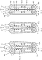
- Figures 1-3 are conceptual views from a different height, that is, in Figure 1 the height position of examining is the top part of the conveyor surfaces, in Figure 2 the height position of examining is the centre part of the conveyor surfaces.
- a suitable degree for convergence that is, wedge angle INCL-D at the level of the top part of the conveyor surfaces B1, B2 (as in Figure 1 ), in particular, is approximately 5-10 degrees, by way of example 8 degrees shown in Figure 1 .
- the inclination position of both conveyor surfaces B1, B2, so at the top part of the conveyor surface pair in such a case one half of the aforementioned degrees, that is, 2.5-5 degrees, in relation to the centre line CL passing between the conveyor surfaces.
- the top part U and lower part L of the conveyor surfaces are best seen in Figures 5 and 7 .
- the comminuting ration that is, crushing ration refers to the ratio between the size of the inlet IN and output OUT1 of the apparatus, and it is between 5-15. for example.
- the size of the inlet should be taken as a function of varying height as in Figures 1-3 depending on the height position of the point of examining (conveyor top part Figure 1 , centre part Figure 2 , lower edge Figure 3).
- Figures 1-3 additionally show that the wedge angle varies from the 8 degrees at the top part ( Figure 1 ) inlet - feed edge to the 0 (zero) degrees at the lower edge ( Figure 3 ) of the conveyor
- Figures 1-3 are horizontal plane, cross-cut, principled views from three planes: Figure 1 top edge where the wedge angle is 8 and the crushing ratio hence approximately 14, Figure 2 centre level between the top and lower edge where the wedge angle INCL-D is 4 and the crushing ratio approximately 7.5 and in addition Figure 3 from the lower edge of the conveyor pair, so at the level of the lower output that is output OUT 1 of the material where the wedge angle INCL-D is approximately 0.5.
- the conveyor surfaces B1, B2 travel along a slightly curved line on the side of the comminuting space GS, the mutual distance between the conveyor surfaces B1, B2 approaching a distance that corresponds to the set value of the output at the lower part L and rear end E2 of the comminuting apparatus/crusher.
- the output OUT1 at the lower edge may either be straight (as seen in the movement direction D) or slightly wedge-like, that is, for example 0.5 degree in Figure 3 so that a particle that has stopped just above the lower edge is compressed before exiting the end E2, but is not necessarily broken.
- Such a weakening may be important in a further process (for example, dissolving) where product particles should have as many micro-cracks as possible.
- the magnitude of the wedge angle INCL-D ( Figure 4 ), that is, the convergence between the conveyor surfaces B1, B2 in the conveying direction, so the movement direction, depends of the height level being examined ( Figures 1-3 from different height levels) and on how the magnitude of the nip angle INCL-TD ( Figure 5 ) changes in this direction.
- the wedge angle (INCL-D) is the largest at the top parts of the comminuting space GS ( Figure 1 ) and its value decreases towards the lower height levels and is at its lowest at the level of the lower edge ( Figure 3 ), where it may be set to zero or otherwise very low. This is why in the comminuting space GS the smallest particles MPD1, MPD2 stopped at the lower levels travel a longer distance during compression and compression is thus slower than with the larger particles MP.
- the apparatus is such that the conveyor surfaces B1, B2 which are placed facing each other which may be brought into movement are arranged to comminute one or more material particles MP comprised by the material for forming one or more smaller daughter particles MPD1 from the material particle MP. It is further the case that the conveyor surfaces B1, B2 that create the convergence in the transverse direction TD in relation to the movement direction are arranged lower in the comminuting space GS to stop the falling movement of such a daughter particle MPD1 formed in the comminuting space GS, to focus a movement in the movement direction on conveyor surfaces B1, B2 also to the daughter particle MPD1.
- the daughter particle proceeds in the movement direction D1 and because the comminuting space is converging, so narrowing, in the movement direction as in Figure 4 and 1 , for example, the daughter particle MPD1 will, at some point of proceeding, be met with such a tight compression that it breaks and from the daughter particle a smaller subparticle MPD2 is created, which as Figure 7 shows falls downward until it stops (as the daughter particle MPD1 but at a lower position and having proceeded further in the movement direction D) between the conveyor surfaces B1, B2 reaching a movement in the movement direction, and the subparticle exits the vertical end gap at the rear end E2 of the device.
- the device settings speed of motion of the conveyor surfaces, nip angle, wedge angle
- the particle size of the incoming material there may also be more height positions for the compression point (three in the above) and particle size categories (three in the above, so incoming particle MP, daughter particle MPD1, and subparticle MD2 of daughter particle).
- the "finished" subparticle MPD2 can exit through output OUT1.
- the incoming particle MP or daughter particle MPD1 is already small enough to exit through the output OUT1 at the lower edge.
- the grading/distribution, conveying and cracking is repeated everywhere in the comminuting space GS particle-specifically in a layer no more than one particle thick.
- the direction TD transverse in relation to the movement direction D, in which direction said transverse convergence exists between the conveyor surfaces, is a substantially perpendicular transverse direction in relation to the movement direction D of the conveyor surfaces. It is furthermore the case that the existing conveyor structures are so positioned that the movement direction D of the conveyor surfaces is substantially horizontal.
- the conveyor structures facing each other are so placed that the direction TD transverse in relation to the movement direction D of the conveyor surfaces is substantially vertical.
- the comminuting is performed in the vertical direction (such as TD) and also in the horizontal direction (such D) in the converging, wedge-like comminuting space GS, the walls of which, so the conveyor surfaces B1, B2, move in the horizontal movement direction D towards the gap-like end, that is, the output OUT1, and the wedge angle of which, so the convergence of the comminuting space GS in the movement direction decreases in the movement direction of the walls, so the conveyor surfaces B1, B2, and from the top part of the front end E1 of which the feed particles, that is, the particles MP in their original size, are dropped into the mouth formed by the walls, that is, the conveyor surfaces B1, B2 at the inlet IN.
- feed particles larger than the gap-like lower part, so the output OUT1 are graded by stopping (because of the convergence according to the nip angle INCL-TD in the transverse direction in relation to the movement direction D, that is, vertical direction) at the height levels according to their sizes, that is, between the conveyor surfaces B1, B2.
- the conveyor surfaces B1, B2 of the comminuting space GS then carry the particles in the movement direction D towards the rear end E2 and at the same time compress the particles that have got wedged between the walls, that is, the conveyor surfaces B1, B2, which may exit directly from the gap-like output OUT2 of the comminuting space GS, or before that crack according to their breaking strength and whereby the created daughter particles (or the latter subparticles MPD2 of the daughter particle) fall in the comminuting space vertically lower either through the output OUT1 at the lower edge, or if the transverse (in relation to movement direction) convergence of the comminuting space GS, so in practise the conveyor surfaces, stops the daughter particle MPD1 still too large, the conveyor surfaces B1, B2 transport the daughter particle in the movement direction towards the output OUT2 in which case the daughter particle MPD1 either breaks during the movement and creates the subparticle MPD2 or exits from the output OUT2 at the rear end E2 of the device.
- Slow compression is implemented successively, also for the daughter pieces created in the cracking, and repeated (that is, the stopping of the falling of the daughter piece due to the nip angle and the continuation of the movement in the movement direction made possible by the stopping) until the size of the resulting particles is small enough, so smaller than the output OUT1 at the lower part of the device.
- Elastic energy stored between the compressions in the compressions is released and the particles must have the chance to change their position before the subsequent compression stage leading to cracking.
- the repetition of such compression-release stages enhances the creation and growth of micro-cracks in the particle parts remaining intact.
- the compression-release cycles are implemented so that the material gradually weakens in all the size categories undergoing compression, also in the size categories preceding the product size (so, the size going to the output OUT1).
- the core of the invention is that in the apparatus the conveyor surfaces B1, B2 are in a double-converging manner so that in addition to said convergence in the movement direction (direction D), so narrowing, the conveyor surfaces B1, B2 are additionally placed in a convergent manner so that the gap between the conveyor surfaces B1, B2 also narrows in the transverse direction TD in relation to the movement direction D.
- the comminuting space GS becomes double-convergent.
- this convergence in the transverse direction TD so nip angle, in relation to the movement direction D, is seen in Figure 4 where the movement direction is away from the viewer.
- nip angle is, for example, 5-20 degrees. This depends of the particle size and size distribution of the material, for example.
- the size of the material particles MP coming in to the inlet IN is between 0.10 - 200 mm, for example.
- the comminuted particle size obtained from the output OUT1 is between 0.1- 5 mm, for example.
- a suitable speed of motion for the conveyor surfaces B1, B2 in the movement direction D, as created by the motors M1A, M2A, is 0.02 - 0.5 m/s, for example.
- the speed of the conveyor surfaces B1, B2 may be adjusted, in particular so that the speed of motion of the conveyor surfaces B1, B2 slightly differs from each other. So, the speed of motion of the conveyor surfaces B1, B2 maybe adjusted to slightly differ from each other.
- the purpose of the speed difference is to increase the effective ares of compression and to cause shear forces and twisting forces in the particle, increasing the micro-cracks. To avoid wear and tear as well as friction, the speed difference must be small, at most 5%, for example.
- the load is directly aimed at the particles.
- the conveyor surfaces B1, B2 comprised by the conveyor structures C1, C2, compression lamellas PL may be slightly turned (either due to their material or fastening) or on the compression lamellas PL, or otherwise, there may be fastened an elastic, continuous band which may be smooth or patterned (symmetrically or asymmetrically, for example) in various ways.
- the purpose of the elastic layer of the conveyor surfaces B1, B2 is to increase the surface area the particle is subjected to when compressed.
- the purpose of the shaping of the conveyor surfaces B1, B2 is to prevent the material pieces from sliding backwards and to boost the cutting force components of the compression.
- the thickness and elasticity of the elastic layer is larger in the top part of the conveyor surfaces B1, B2 (than in the lower part), in which top part the transitions leading to cracking are larger due to the bigger size of the particles, compared to the lamellas at the lower part where the wedge load is lighter.
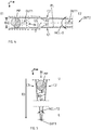
- FIG. 6 is a schematic view of the conveyor structure, illustrating the adjustment structures. The adjustment may be performed on the conveyor structure C1, C2 or directly on the actual conveyor surface B1, B2.
- the device structures for performing the various adjustments may be partly or entirely the same device structures AD1-AD4.
- the apparatus thus comprises adjustment means AD1-AD4 for the conveyor surfaces B1, B2 for adjusting the convergence angle INCL-D of the convergence in the movement direction, so the wedge angle, and the same or different adjustment means for adjusting the convergence angle INCL-TD of the convergence in the direction TD transverse in relation to the movement direction D, so the nip angle, and the same or different adjustment means for adjusting the speed of motion and distance between the conveyor surfaces B1, B2.
- Figure 6 shows the adjustment means AD1-AD4 of one conveyor structure C1, the structures may be similar in the second conveyor structure C2, also ( Figure 6 only show a bottom corner), the location of which would in Figure 6 be on the left side of the conveyor structure C1 or in parallel with it.
- the adjustment means AD1-AD4 may be mutually similar, so the structure of the adjustment means is discussed as relates to the adjustment means AD1, in particular.
- the conveyor structure C1 is shown as seen from the inlet side IN at the front end E1.
- Figure 6 shows end axles A1 and A2 of the conveyor structure, and at the lower end of the axle A1, a rotating motor M1A and at the lower end A2 a rotating motor M1B, if required.
- the adjustment means AD1 comprise an actuator HM1, such as a hydraulic motor / hydraulic piston HM1, and a support member SM1 such as a slide rail SM1 by means of which the actuator HM1 moves in the spot in question a subentity that includes the end axle A1 with its bearing housing, the drive gear GE1, rotating motor M1A of the end axle.
- an actuator HM1 such as a hydraulic motor / hydraulic piston HM1
- a support member SM1 such as a slide rail SM1 by means of which the actuator HM1 moves in the spot in question a subentity that includes the end axle A1 with its bearing housing, the drive gear GE1, rotating motor M1A of the end axle.
- Each of the conveyor structures C1, C2 may be separately adjusted with the adjustment means AD1-AD4 within the limits set for the device.
- the distance between the conveyor surfaces B1, B2 as well as the nip angle INCL-TD and wedge angle INCL-D are adjusted, so the relative transition created by the conveyors and the sizes of the inlet IN or output OUT1, OUT2 may be adjusted.
- the conveying speed of each conveyor surface B1, B2 consisting of lamellas and/or a belt is adjusted according to the material properties and capacity with the speeds of the motors M1A, M2A.
- the adjustment of the wedge angle INCL-D, so the convergence in the movement direction, is performed for the conveyor C1 by adjusting, with the adjustment structures AD2 (actuator HM2, in particular), AD4 at the front edge E1 of the conveyor, the conveyor C1 to move by its front edge E1 more to the right horizontally, so away from the second conveyor structure (C2, only lower corner seen in Figure 6 ).
- the adjustment of the nip angle INCL-TD, so the convergence in the transverse direction in relation to the movement direction, is carried out by adjusting the top edge of the conveyor structure C1 by the adjustment structures AD3, AD4 therein to tilt more to the right, that is, away from the second conveyor structure (C2, only lower corner seen in Figure 6 ).
- the method is next examined in closer detail.
- material containing material particles MP is conveyed by the movement of conveyor surfaces B1, B2 in opposing conveyor structures C1, C2 of the comminuting apparatus in the movement direction D in the comminuting space GS between the conveyor surfaces.
- the material particles are comminuted when examined in the movement direction D in a converging comminuting space between conveyor surfaces so that one or more daughter particles MPD1 are formed from the material particle MP by comminuting with the aid of the compression created by the moving conveyor surfaces B1, B2.
- the core of the method is that the method uses said conveyor surfaces B1, B2 defining the comminuting space D, in which method the comminuting space GS is also convergent when examined in the transverse direction in relation to the movement direction, the converging conveyor surfaces B1, B2 stopping between the conveyor surfaces the falling movement of such a daughter particle MPD1 formed in the comminuting space GS, after which with these still moving conveyor surfaces, a movement into the movement direction is also achieved for one or more daughter particles MPD1.
- the daughter particle MPD1 is conveyed by the movement of conveyor surfaces in the opposing conveyor structures of the comminuting apparatus in the movement direction D in the comminuting space between the conveyor surfaces B1, B2.
- the daughter particle MPD1 is conveyed further and further in the movement direction D, the daughter particle is comminuted, when examined in the movement direction D, in a converging (angle INCL-D Figure 4 ) comminuting space between conveyor surfaces so that one or more subparticles of the daughter particles are formed from the daughter particle by comminuting with the aid of the compression created by the moving conveyor surfaces.
- daughter particles MPD1 and/or subparticles MPD2 of daughter particles and/or still smaller material particles comminuted from subparticles are removed from the comminuting space through the output at the rear end, so output OUT2, of the comminuting space, where the movement direction D is directed. This takes place when the particle size during comminuting remains larger than the output OUT1 at the lower edge of the apparatus.
- the exit of daughter pieces may be primarily boosted by a gas flow or, if further processing so dictates, with a fluid flow, such as water.
- the material being comminuted may be dried, or when a chemically appropriate inert gas is used (in other words, the proportion of nitrogen or carbon dioxide in the gas), it is possible to control the chemical state of the surfaces parts of the material particles. With a liquid flow, the redox state of the particles may be controlled, if it is justified to perform further processing with a flotation process.
- a chemically appropriate inert gas in other words, the proportion of nitrogen or carbon dioxide in the gas
- the compression of particles in the comminuting space GS is performed at different times as the particle size decreases and as successive events when the conveyor surfaces B1, B2 stop all the particles too big for a product according to their sizes at the height level according to the nip angle INCL-TD for further compression.
Landscapes
- Engineering & Computer Science (AREA)
- Food Science & Technology (AREA)
- Mechanical Engineering (AREA)
- Disintegrating Or Milling (AREA)
- Attitude Control For Articles On Conveyors (AREA)
- Crushing And Pulverization Processes (AREA)
- Processing And Handling Of Plastics And Other Materials For Molding In General (AREA)
- Crushing And Grinding (AREA)
- Control Of Conveyors (AREA)
Priority Applications (1)
| Application Number | Priority Date | Filing Date | Title |
|---|---|---|---|
| PL17865680T PL3532204T3 (pl) | 2016-10-27 | 2017-10-27 | Urządzenie i sposób rozdrabniania materiału |
Applications Claiming Priority (2)
| Application Number | Priority Date | Filing Date | Title |
|---|---|---|---|
| FI20165813A FI127385B (fi) | 2016-10-27 | 2016-10-27 | Laitteisto ja menetelmä materiaalin hienontamiseen |
| PCT/FI2017/050743 WO2018078221A1 (en) | 2016-10-27 | 2017-10-27 | Apparatus and method for comminuting of material |
Publications (3)
| Publication Number | Publication Date |
|---|---|
| EP3532204A1 EP3532204A1 (en) | 2019-09-04 |
| EP3532204A4 EP3532204A4 (en) | 2020-07-15 |
| EP3532204B1 true EP3532204B1 (en) | 2021-09-08 |
Family
ID=62016946
Family Applications (1)
| Application Number | Title | Priority Date | Filing Date |
|---|---|---|---|
| EP17865680.7A Active EP3532204B1 (en) | 2016-10-27 | 2017-10-27 | Apparatus and method for comminuting of material |
Country Status (9)
| Country | Link |
|---|---|
| US (2) | US10857545B2 (pl) |
| EP (1) | EP3532204B1 (pl) |
| CN (1) | CN110099749B (pl) |
| AU (1) | AU2017348754B2 (pl) |
| CA (1) | CA3080295A1 (pl) |
| ES (1) | ES2900192T3 (pl) |
| FI (1) | FI127385B (pl) |
| PL (1) | PL3532204T3 (pl) |
| WO (1) | WO2018078221A1 (pl) |
Families Citing this family (3)
| Publication number | Priority date | Publication date | Assignee | Title |
|---|---|---|---|---|
| CN113522162B (zh) * | 2021-07-14 | 2023-02-07 | 爱驷骐辊压机(杭州)有限责任公司 | 一种多楔带折裂式破碎造粒机 |
| CN114534880B (zh) * | 2022-02-14 | 2023-07-11 | 江苏鹏飞集团股份有限公司 | 外置辊面多用途辊压机 |
| CN115990532A (zh) * | 2023-02-13 | 2023-04-21 | 中国农业科学院兰州畜牧与兽药研究所 | 一种饲料生产用配料装置及其使用方法 |
Family Cites Families (24)
| Publication number | Priority date | Publication date | Assignee | Title |
|---|---|---|---|---|
| US1448013A (en) | 1921-11-07 | 1923-03-13 | James A Warren | Crushing and grinding machine |
| US1704823A (en) * | 1926-10-01 | 1929-03-12 | Denny James John | Crushing machine |
| DE585915C (de) | 1933-03-18 | 1933-10-12 | Adolf Steinbrueckner | Brechermuehle fuer Hart- und Weichgut |
| US2150984A (en) * | 1937-04-19 | 1939-03-21 | Los Angeles By Products Co | Combined crushing and feeding device for junk shredding machines |
| BE511258A (pl) | 1951-05-11 | |||
| US2959364A (en) * | 1956-08-15 | 1960-11-08 | Allis Chalmers Mfg Co | Comminution apparatus |
| US2981486A (en) * | 1956-12-24 | 1961-04-25 | Goto Jyun-Ichi | Low pressure flour mill |
| US3691942A (en) * | 1971-06-03 | 1972-09-19 | Allen Wagley | Crusher |
| US4285373A (en) | 1979-10-15 | 1981-08-25 | Buchanan Robert H | Crushing apparatus |
| JPS6050494B2 (ja) * | 1981-05-22 | 1985-11-08 | 日本原子力発電株式会社 | 破断機 |
| NL8303265A (nl) | 1983-09-23 | 1985-04-16 | Vam Nv | Inrichting voor het bewerken van met afvalmateriaal gevulde zakken. |
| US4995314A (en) * | 1989-10-23 | 1991-02-26 | Midamerica Recycling Company | Can flattening machine |
| JPH07101501A (ja) | 1993-08-11 | 1995-04-18 | Fuji Electric Co Ltd | 紙容器の回収装置 |
| DE4429326C1 (de) * | 1994-08-18 | 1995-12-14 | Hetzel & Co Elek Recycling | Verfahren und Vorrichtung zur Aufbereitung von Lampen |
| US5522311A (en) * | 1995-05-12 | 1996-06-04 | Tomra Systems A/S | Beverage container compacting device having endless belts with puncturing members |
| US5713269A (en) * | 1996-04-11 | 1998-02-03 | Recycling Equipment | Refuse assembly for reducing the size of deformable objects |
| DE19817274A1 (de) | 1998-04-18 | 1999-10-28 | Cemag Gmbh | Verfahren und Vorrichtung zur Feinzerkleinerung von mineralischen und nichtmineralischen Stoffen |
| CN2475936Y (zh) | 2001-03-30 | 2002-02-06 | 周广胜 | 垃圾搓挤破碎脱水装置 |
| JP2006231267A (ja) | 2005-02-28 | 2006-09-07 | Kinugawa Tekkosho:Kk | 破袋・除袋装置 |
| NL2004700C2 (nl) * | 2010-05-11 | 2011-11-14 | Koos Jacobus Schenk | Breekinrichting. |
| CN102371199A (zh) | 2010-08-05 | 2012-03-14 | 宜兴市普阳能源设备有限公司 | 鄂式破碎机 |
| EP2980315A1 (en) * | 2012-06-29 | 2016-02-03 | E-MAK Makine Insaat Ticaret Ve Sanayi A.S. | A crushing machine |
| CN203803567U (zh) | 2013-10-18 | 2014-09-03 | 孟伟行 | 层磨机 |
| CN105859099B (zh) | 2016-05-31 | 2018-09-04 | 泰州市蓝海环保科技有限公司 | 双向压缩式污泥脱水机 |
-
2016
- 2016-10-27 FI FI20165813A patent/FI127385B/fi active IP Right Grant
-
2017
- 2017-10-27 US US16/090,703 patent/US10857545B2/en active Active - Reinstated
- 2017-10-27 PL PL17865680T patent/PL3532204T3/pl unknown
- 2017-10-27 WO PCT/FI2017/050743 patent/WO2018078221A1/en not_active Ceased
- 2017-10-27 CN CN201780079087.8A patent/CN110099749B/zh active Active
- 2017-10-27 AU AU2017348754A patent/AU2017348754B2/en active Active
- 2017-10-27 ES ES17865680T patent/ES2900192T3/es active Active
- 2017-10-27 CA CA3080295A patent/CA3080295A1/en active Pending
- 2017-10-27 EP EP17865680.7A patent/EP3532204B1/en active Active
-
2020
- 2020-09-25 US US16/948,645 patent/US11731141B2/en active Active
Also Published As
| Publication number | Publication date |
|---|---|
| US20190118189A1 (en) | 2019-04-25 |
| US20210008567A1 (en) | 2021-01-14 |
| PL3532204T3 (pl) | 2022-02-07 |
| EP3532204A4 (en) | 2020-07-15 |
| CN110099749B (zh) | 2021-12-24 |
| ES2900192T3 (es) | 2022-03-16 |
| AU2017348754B2 (en) | 2023-02-23 |
| FI20165813A7 (fi) | 2018-04-28 |
| US11731141B2 (en) | 2023-08-22 |
| EP3532204A1 (en) | 2019-09-04 |
| AU2017348754A1 (en) | 2019-05-30 |
| CN110099749A (zh) | 2019-08-06 |
| CA3080295A1 (en) | 2018-05-03 |
| FI127385B (fi) | 2018-04-30 |
| US10857545B2 (en) | 2020-12-08 |
| WO2018078221A1 (en) | 2018-05-03 |
Similar Documents
| Publication | Publication Date | Title |
|---|---|---|
| US11731141B2 (en) | Apparatus and method for comminuting of material | |
| JP5409634B2 (ja) | 鉱物性または非鉱物性材料の粉砕のための方法および装置 | |
| CN114007750B (zh) | 用于粉碎的设备、系统和方法 | |
| CN106395319A (zh) | 一种可调角度缓冲溜槽 | |
| RU2464097C1 (ru) | Способ дробления-измельчения полиминеральных рудных материалов, содержащих драгоценные камни, и дробильно-измельчительная машина для его осуществления (варианты) | |
| CN112295924A (zh) | 一种煤矸石分选装置 | |
| CN211894798U (zh) | 一种多功能食品机械输送带分类装置 | |
| CN102430457A (zh) | 多功能卧式旋回破碎机 | |
| CN102861668A (zh) | 一种干式磁滚筒粗抛尾装置 | |
| US2899139A (en) | Method and apparatus for concentrating and classifying material | |
| Knapp et al. | HPGR: Why skewing is a requirement for operational applications | |
| CN112387344A (zh) | 一种带有除铁功能的圆锥破碎机及使用方法 | |
| CN114345895A (zh) | 一种易拉罐破碎生产线 | |
| FI131593B1 (fi) | Hienojauhantalaitteisto ja menetelmä teräskuonan jauhamiseen | |
| CN217888147U (zh) | 一种减少过粉碎的破碎机给料结构 | |
| CN208427388U (zh) | 一种带阻料机构的皮带输送机 | |
| CN202387532U (zh) | 多功能卧式旋回破碎机 | |
| CN115845965B (zh) | 一种优化分选效果的分选装置 | |
| US807659A (en) | Ore separating and concentrating machine. | |
| CN211725958U (zh) | 一种水泥生产的辊压机 | |
| CN207209461U (zh) | 一种分料螺旋输送装置 | |
| CN201419116Y (zh) | 物料粉碎系统的喂料机构 | |
| CN121060700A (zh) | 一种滚动摇床及其操作方法 | |
| EP0013094A1 (en) | Coal and mineral cleaning process and apparatus using shock frequency separation | |
| Raberger et al. | New control head design for hyperbaric disk filter gives better performance and longer life-time |
Legal Events
| Date | Code | Title | Description |
|---|---|---|---|
| STAA | Information on the status of an ep patent application or granted ep patent |
Free format text: STATUS: THE INTERNATIONAL PUBLICATION HAS BEEN MADE |
|
| PUAI | Public reference made under article 153(3) epc to a published international application that has entered the european phase |
Free format text: ORIGINAL CODE: 0009012 |
|
| STAA | Information on the status of an ep patent application or granted ep patent |
Free format text: STATUS: REQUEST FOR EXAMINATION WAS MADE |
|
| 17P | Request for examination filed |
Effective date: 20190521 |
|
| AK | Designated contracting states |
Kind code of ref document: A1 Designated state(s): AL AT BE BG CH CY CZ DE DK EE ES FI FR GB GR HR HU IE IS IT LI LT LU LV MC MK MT NL NO PL PT RO RS SE SI SK SM TR |
|
| AX | Request for extension of the european patent |
Extension state: BA ME |
|
| DAV | Request for validation of the european patent (deleted) | ||
| DAX | Request for extension of the european patent (deleted) | ||
| A4 | Supplementary search report drawn up and despatched |
Effective date: 20200615 |
|
| RIC1 | Information provided on ipc code assigned before grant |
Ipc: B02C 1/02 20060101ALI20200608BHEP Ipc: B02C 19/00 20060101AFI20200608BHEP Ipc: B02C 1/06 20060101ALI20200608BHEP Ipc: B02C 1/10 20060101ALI20200608BHEP Ipc: B02C 18/00 20060101ALI20200608BHEP |
|
| RAP1 | Party data changed (applicant data changed or rights of an application transferred) |
Owner name: TEVO OY |
|
| GRAP | Despatch of communication of intention to grant a patent |
Free format text: ORIGINAL CODE: EPIDOSNIGR1 |
|
| STAA | Information on the status of an ep patent application or granted ep patent |
Free format text: STATUS: GRANT OF PATENT IS INTENDED |
|
| INTG | Intention to grant announced |
Effective date: 20210429 |
|
| GRAS | Grant fee paid |
Free format text: ORIGINAL CODE: EPIDOSNIGR3 |
|
| GRAA | (expected) grant |
Free format text: ORIGINAL CODE: 0009210 |
|
| STAA | Information on the status of an ep patent application or granted ep patent |
Free format text: STATUS: THE PATENT HAS BEEN GRANTED |
|
| AK | Designated contracting states |
Kind code of ref document: B1 Designated state(s): AL AT BE BG CH CY CZ DE DK EE ES FI FR GB GR HR HU IE IS IT LI LT LU LV MC MK MT NL NO PL PT RO RS SE SI SK SM TR |
|
| REG | Reference to a national code |
Ref country code: GB Ref legal event code: FG4D |
|
| REG | Reference to a national code |
Ref country code: CH Ref legal event code: EP Ref country code: AT Ref legal event code: REF Ref document number: 1428086 Country of ref document: AT Kind code of ref document: T Effective date: 20210915 |
|
| REG | Reference to a national code |
Ref country code: DE Ref legal event code: R096 Ref document number: 602017045845 Country of ref document: DE |
|
| REG | Reference to a national code |
Ref country code: IE Ref legal event code: FG4D |
|
| REG | Reference to a national code |
Ref country code: SE Ref legal event code: TRGR |
|
| REG | Reference to a national code |
Ref country code: LT Ref legal event code: MG9D |
|
| REG | Reference to a national code |
Ref country code: NL Ref legal event code: MP Effective date: 20210908 |
|
| PG25 | Lapsed in a contracting state [announced via postgrant information from national office to epo] |
Ref country code: RS Free format text: LAPSE BECAUSE OF FAILURE TO SUBMIT A TRANSLATION OF THE DESCRIPTION OR TO PAY THE FEE WITHIN THE PRESCRIBED TIME-LIMIT Effective date: 20210908 Ref country code: HR Free format text: LAPSE BECAUSE OF FAILURE TO SUBMIT A TRANSLATION OF THE DESCRIPTION OR TO PAY THE FEE WITHIN THE PRESCRIBED TIME-LIMIT Effective date: 20210908 Ref country code: FI Free format text: LAPSE BECAUSE OF FAILURE TO SUBMIT A TRANSLATION OF THE DESCRIPTION OR TO PAY THE FEE WITHIN THE PRESCRIBED TIME-LIMIT Effective date: 20210908 Ref country code: LT Free format text: LAPSE BECAUSE OF FAILURE TO SUBMIT A TRANSLATION OF THE DESCRIPTION OR TO PAY THE FEE WITHIN THE PRESCRIBED TIME-LIMIT Effective date: 20210908 Ref country code: BG Free format text: LAPSE BECAUSE OF FAILURE TO SUBMIT A TRANSLATION OF THE DESCRIPTION OR TO PAY THE FEE WITHIN THE PRESCRIBED TIME-LIMIT Effective date: 20211208 |
|
| REG | Reference to a national code |
Ref country code: NO Ref legal event code: T2 Effective date: 20210908 |
|
| PG25 | Lapsed in a contracting state [announced via postgrant information from national office to epo] |
Ref country code: LV Free format text: LAPSE BECAUSE OF FAILURE TO SUBMIT A TRANSLATION OF THE DESCRIPTION OR TO PAY THE FEE WITHIN THE PRESCRIBED TIME-LIMIT Effective date: 20210908 Ref country code: GR Free format text: LAPSE BECAUSE OF FAILURE TO SUBMIT A TRANSLATION OF THE DESCRIPTION OR TO PAY THE FEE WITHIN THE PRESCRIBED TIME-LIMIT Effective date: 20211209 |
|
| REG | Reference to a national code |
Ref country code: ES Ref legal event code: FG2A Ref document number: 2900192 Country of ref document: ES Kind code of ref document: T3 Effective date: 20220316 |
|
| REG | Reference to a national code |
Ref country code: CH Ref legal event code: PL |
|
| PG25 | Lapsed in a contracting state [announced via postgrant information from national office to epo] |
Ref country code: IS Free format text: LAPSE BECAUSE OF FAILURE TO SUBMIT A TRANSLATION OF THE DESCRIPTION OR TO PAY THE FEE WITHIN THE PRESCRIBED TIME-LIMIT Effective date: 20220108 Ref country code: SM Free format text: LAPSE BECAUSE OF FAILURE TO SUBMIT A TRANSLATION OF THE DESCRIPTION OR TO PAY THE FEE WITHIN THE PRESCRIBED TIME-LIMIT Effective date: 20210908 Ref country code: SK Free format text: LAPSE BECAUSE OF FAILURE TO SUBMIT A TRANSLATION OF THE DESCRIPTION OR TO PAY THE FEE WITHIN THE PRESCRIBED TIME-LIMIT Effective date: 20210908 Ref country code: RO Free format text: LAPSE BECAUSE OF FAILURE TO SUBMIT A TRANSLATION OF THE DESCRIPTION OR TO PAY THE FEE WITHIN THE PRESCRIBED TIME-LIMIT Effective date: 20210908 Ref country code: PT Free format text: LAPSE BECAUSE OF FAILURE TO SUBMIT A TRANSLATION OF THE DESCRIPTION OR TO PAY THE FEE WITHIN THE PRESCRIBED TIME-LIMIT Effective date: 20220110 Ref country code: NL Free format text: LAPSE BECAUSE OF FAILURE TO SUBMIT A TRANSLATION OF THE DESCRIPTION OR TO PAY THE FEE WITHIN THE PRESCRIBED TIME-LIMIT Effective date: 20210908 Ref country code: EE Free format text: LAPSE BECAUSE OF FAILURE TO SUBMIT A TRANSLATION OF THE DESCRIPTION OR TO PAY THE FEE WITHIN THE PRESCRIBED TIME-LIMIT Effective date: 20210908 Ref country code: CZ Free format text: LAPSE BECAUSE OF FAILURE TO SUBMIT A TRANSLATION OF THE DESCRIPTION OR TO PAY THE FEE WITHIN THE PRESCRIBED TIME-LIMIT Effective date: 20210908 Ref country code: AL Free format text: LAPSE BECAUSE OF FAILURE TO SUBMIT A TRANSLATION OF THE DESCRIPTION OR TO PAY THE FEE WITHIN THE PRESCRIBED TIME-LIMIT Effective date: 20210908 |
|
| REG | Reference to a national code |
Ref country code: DE Ref legal event code: R097 Ref document number: 602017045845 Country of ref document: DE |
|
| REG | Reference to a national code |
Ref country code: BE Ref legal event code: MM Effective date: 20211031 |
|
| PG25 | Lapsed in a contracting state [announced via postgrant information from national office to epo] |
Ref country code: MC Free format text: LAPSE BECAUSE OF FAILURE TO SUBMIT A TRANSLATION OF THE DESCRIPTION OR TO PAY THE FEE WITHIN THE PRESCRIBED TIME-LIMIT Effective date: 20210908 |
|
| PLBE | No opposition filed within time limit |
Free format text: ORIGINAL CODE: 0009261 |
|
| STAA | Information on the status of an ep patent application or granted ep patent |
Free format text: STATUS: NO OPPOSITION FILED WITHIN TIME LIMIT |
|
| PG25 | Lapsed in a contracting state [announced via postgrant information from national office to epo] |
Ref country code: LU Free format text: LAPSE BECAUSE OF NON-PAYMENT OF DUE FEES Effective date: 20211027 Ref country code: DK Free format text: LAPSE BECAUSE OF FAILURE TO SUBMIT A TRANSLATION OF THE DESCRIPTION OR TO PAY THE FEE WITHIN THE PRESCRIBED TIME-LIMIT Effective date: 20210908 Ref country code: BE Free format text: LAPSE BECAUSE OF NON-PAYMENT OF DUE FEES Effective date: 20211031 |
|
| 26N | No opposition filed |
Effective date: 20220609 |
|
| PG25 | Lapsed in a contracting state [announced via postgrant information from national office to epo] |
Ref country code: SI Free format text: LAPSE BECAUSE OF FAILURE TO SUBMIT A TRANSLATION OF THE DESCRIPTION OR TO PAY THE FEE WITHIN THE PRESCRIBED TIME-LIMIT Effective date: 20210908 Ref country code: LI Free format text: LAPSE BECAUSE OF NON-PAYMENT OF DUE FEES Effective date: 20211031 Ref country code: CH Free format text: LAPSE BECAUSE OF NON-PAYMENT OF DUE FEES Effective date: 20211031 |
|
| PG25 | Lapsed in a contracting state [announced via postgrant information from national office to epo] |
Ref country code: IE Free format text: LAPSE BECAUSE OF NON-PAYMENT OF DUE FEES Effective date: 20211027 |
|
| PG25 | Lapsed in a contracting state [announced via postgrant information from national office to epo] |
Ref country code: FR Free format text: LAPSE BECAUSE OF NON-PAYMENT OF DUE FEES Effective date: 20211108 |
|
| REG | Reference to a national code |
Ref country code: AT Ref legal event code: UEP Ref document number: 1428086 Country of ref document: AT Kind code of ref document: T Effective date: 20210908 |
|
| PG25 | Lapsed in a contracting state [announced via postgrant information from national office to epo] |
Ref country code: CY Free format text: LAPSE BECAUSE OF FAILURE TO SUBMIT A TRANSLATION OF THE DESCRIPTION OR TO PAY THE FEE WITHIN THE PRESCRIBED TIME-LIMIT Effective date: 20210908 |
|
| PG25 | Lapsed in a contracting state [announced via postgrant information from national office to epo] |
Ref country code: HU Free format text: LAPSE BECAUSE OF FAILURE TO SUBMIT A TRANSLATION OF THE DESCRIPTION OR TO PAY THE FEE WITHIN THE PRESCRIBED TIME-LIMIT; INVALID AB INITIO Effective date: 20171027 |
|
| PG25 | Lapsed in a contracting state [announced via postgrant information from national office to epo] |
Ref country code: MK Free format text: LAPSE BECAUSE OF FAILURE TO SUBMIT A TRANSLATION OF THE DESCRIPTION OR TO PAY THE FEE WITHIN THE PRESCRIBED TIME-LIMIT Effective date: 20210908 |
|
| PG25 | Lapsed in a contracting state [announced via postgrant information from national office to epo] |
Ref country code: MT Free format text: LAPSE BECAUSE OF FAILURE TO SUBMIT A TRANSLATION OF THE DESCRIPTION OR TO PAY THE FEE WITHIN THE PRESCRIBED TIME-LIMIT Effective date: 20210908 |
|
| PGFP | Annual fee paid to national office [announced via postgrant information from national office to epo] |
Ref country code: ES Payment date: 20241127 Year of fee payment: 8 |
|
| REG | Reference to a national code |
Ref country code: DE Ref legal event code: R082 Ref document number: 602017045845 Country of ref document: DE Representative=s name: WUESTHOFF & WUESTHOFF PATENTANWAELTE UND RECHT, DE |
|
| PGFP | Annual fee paid to national office [announced via postgrant information from national office to epo] |
Ref country code: DE Payment date: 20251023 Year of fee payment: 9 |
|
| PGFP | Annual fee paid to national office [announced via postgrant information from national office to epo] |
Ref country code: GB Payment date: 20251027 Year of fee payment: 9 |
|
| PGFP | Annual fee paid to national office [announced via postgrant information from national office to epo] |
Ref country code: NO Payment date: 20251024 Year of fee payment: 9 |
|
| PGFP | Annual fee paid to national office [announced via postgrant information from national office to epo] |
Ref country code: AT Payment date: 20251023 Year of fee payment: 9 |
|
| PGFP | Annual fee paid to national office [announced via postgrant information from national office to epo] |
Ref country code: IT Payment date: 20251023 Year of fee payment: 9 |
|
| PGFP | Annual fee paid to national office [announced via postgrant information from national office to epo] |
Ref country code: TR Payment date: 20251023 Year of fee payment: 9 |
|
| PGFP | Annual fee paid to national office [announced via postgrant information from national office to epo] |
Ref country code: SE Payment date: 20251023 Year of fee payment: 9 |
|
| PGFP | Annual fee paid to national office [announced via postgrant information from national office to epo] |
Ref country code: PL Payment date: 20251024 Year of fee payment: 9 |