EP3531787B1 - Procédé de communication multiconnexion basé sur un faisceau d'ondes, dispositif terminal, et dispositif de réseau - Google Patents
Procédé de communication multiconnexion basé sur un faisceau d'ondes, dispositif terminal, et dispositif de réseau Download PDFInfo
- Publication number
- EP3531787B1 EP3531787B1 EP17868407.2A EP17868407A EP3531787B1 EP 3531787 B1 EP3531787 B1 EP 3531787B1 EP 17868407 A EP17868407 A EP 17868407A EP 3531787 B1 EP3531787 B1 EP 3531787B1
- Authority
- EP
- European Patent Office
- Prior art keywords
- sub
- base station
- beams
- terminal device
- network device
- Prior art date
- Legal status (The legal status is an assumption and is not a legal conclusion. Google has not performed a legal analysis and makes no representation as to the accuracy of the status listed.)
- Active
Links
- 238000004891 communication Methods 0.000 title claims description 86
- 238000000034 method Methods 0.000 title claims description 66
- 238000012545 processing Methods 0.000 claims description 43
- 238000005259 measurement Methods 0.000 claims description 42
- 230000008569 process Effects 0.000 description 28
- 230000004044 response Effects 0.000 description 24
- 230000011664 signaling Effects 0.000 description 22
- 238000010586 diagram Methods 0.000 description 21
- 230000006870 function Effects 0.000 description 15
- 230000015654 memory Effects 0.000 description 13
- 238000005516 engineering process Methods 0.000 description 12
- 230000003993 interaction Effects 0.000 description 12
- 230000005540 biological transmission Effects 0.000 description 8
- 238000012217 deletion Methods 0.000 description 4
- 230000037430 deletion Effects 0.000 description 4
- 238000013461 design Methods 0.000 description 4
- LKKMLIBUAXYLOY-UHFFFAOYSA-N 3-Amino-1-methyl-5H-pyrido[4,3-b]indole Chemical compound N1C2=CC=CC=C2C2=C1C=C(N)N=C2C LKKMLIBUAXYLOY-UHFFFAOYSA-N 0.000 description 2
- 101150006914 TRP1 gene Proteins 0.000 description 2
- LVTKHGUGBGNBPL-UHFFFAOYSA-N Trp-P-1 Chemical compound N1C2=CC=CC=C2C2=C1C(C)=C(N)N=C2C LVTKHGUGBGNBPL-UHFFFAOYSA-N 0.000 description 2
- 230000008859 change Effects 0.000 description 2
- 230000000737 periodic effect Effects 0.000 description 2
- 230000009471 action Effects 0.000 description 1
- 230000010267 cellular communication Effects 0.000 description 1
- 230000001413 cellular effect Effects 0.000 description 1
- 239000002131 composite material Substances 0.000 description 1
- 125000004122 cyclic group Chemical group 0.000 description 1
- 230000001419 dependent effect Effects 0.000 description 1
- 230000007774 longterm Effects 0.000 description 1
- 238000013507 mapping Methods 0.000 description 1
- 230000009467 reduction Effects 0.000 description 1
- 230000001960 triggered effect Effects 0.000 description 1
Images


Classifications
-
- H—ELECTRICITY
- H04—ELECTRIC COMMUNICATION TECHNIQUE
- H04W—WIRELESS COMMUNICATION NETWORKS
- H04W24/00—Supervisory, monitoring or testing arrangements
- H04W24/04—Arrangements for maintaining operational condition
-
- H—ELECTRICITY
- H04—ELECTRIC COMMUNICATION TECHNIQUE
- H04B—TRANSMISSION
- H04B7/00—Radio transmission systems, i.e. using radiation field
- H04B7/02—Diversity systems; Multi-antenna system, i.e. transmission or reception using multiple antennas
- H04B7/04—Diversity systems; Multi-antenna system, i.e. transmission or reception using multiple antennas using two or more spaced independent antennas
- H04B7/08—Diversity systems; Multi-antenna system, i.e. transmission or reception using multiple antennas using two or more spaced independent antennas at the receiving station
- H04B7/0868—Hybrid systems, i.e. switching and combining
- H04B7/088—Hybrid systems, i.e. switching and combining using beam selection
-
- H—ELECTRICITY
- H04—ELECTRIC COMMUNICATION TECHNIQUE
- H04W—WIRELESS COMMUNICATION NETWORKS
- H04W74/00—Wireless channel access, e.g. scheduled or random access
- H04W74/08—Non-scheduled or contention based access, e.g. random access, ALOHA, CSMA [Carrier Sense Multiple Access]
-
- H—ELECTRICITY
- H04—ELECTRIC COMMUNICATION TECHNIQUE
- H04B—TRANSMISSION
- H04B7/00—Radio transmission systems, i.e. using radiation field
- H04B7/02—Diversity systems; Multi-antenna system, i.e. transmission or reception using multiple antennas
- H04B7/04—Diversity systems; Multi-antenna system, i.e. transmission or reception using multiple antennas using two or more spaced independent antennas
- H04B7/06—Diversity systems; Multi-antenna system, i.e. transmission or reception using multiple antennas using two or more spaced independent antennas at the transmitting station
- H04B7/0613—Diversity systems; Multi-antenna system, i.e. transmission or reception using multiple antennas using two or more spaced independent antennas at the transmitting station using simultaneous transmission
- H04B7/0615—Diversity systems; Multi-antenna system, i.e. transmission or reception using multiple antennas using two or more spaced independent antennas at the transmitting station using simultaneous transmission of weighted versions of same signal
- H04B7/0617—Diversity systems; Multi-antenna system, i.e. transmission or reception using multiple antennas using two or more spaced independent antennas at the transmitting station using simultaneous transmission of weighted versions of same signal for beam forming
-
- H—ELECTRICITY
- H04—ELECTRIC COMMUNICATION TECHNIQUE
- H04B—TRANSMISSION
- H04B7/00—Radio transmission systems, i.e. using radiation field
- H04B7/02—Diversity systems; Multi-antenna system, i.e. transmission or reception using multiple antennas
- H04B7/04—Diversity systems; Multi-antenna system, i.e. transmission or reception using multiple antennas using two or more spaced independent antennas
- H04B7/06—Diversity systems; Multi-antenna system, i.e. transmission or reception using multiple antennas using two or more spaced independent antennas at the transmitting station
- H04B7/0686—Hybrid systems, i.e. switching and simultaneous transmission
- H04B7/0695—Hybrid systems, i.e. switching and simultaneous transmission using beam selection
-
- H—ELECTRICITY
- H04—ELECTRIC COMMUNICATION TECHNIQUE
- H04W—WIRELESS COMMUNICATION NETWORKS
- H04W24/00—Supervisory, monitoring or testing arrangements
- H04W24/08—Testing, supervising or monitoring using real traffic
-
- H—ELECTRICITY
- H04—ELECTRIC COMMUNICATION TECHNIQUE
- H04W—WIRELESS COMMUNICATION NETWORKS
- H04W76/00—Connection management
- H04W76/10—Connection setup
-
- H—ELECTRICITY
- H04—ELECTRIC COMMUNICATION TECHNIQUE
- H04W—WIRELESS COMMUNICATION NETWORKS
- H04W16/00—Network planning, e.g. coverage or traffic planning tools; Network deployment, e.g. resource partitioning or cells structures
- H04W16/24—Cell structures
- H04W16/28—Cell structures using beam steering
Definitions
- the present invention relates to the high-frequency wireless communication field, and in particular, to a beam-based multi-connection communication method, a terminal device, and a network device.
- a beam path loss increases as a frequency increases, and a cell coverage area is reduced.
- the access network devices may be base stations or transmission reception points (TRP)
- TRP transmission reception points
- a beamforming technology that is, a multi-antenna processing technology
- a beamforming technology is used to form a narrow beam by using a plurality of antennas, to increase a beam gain and compensate for a path loss to some extent.
- a region A is a low-frequency coverage area
- a region B is a high-frequency coverage area
- a region C is a narrow-beam coverage area
- L is a cell boundary covered by a base station. Because a beam gain of a narrow beam is relatively high, a path loss at a high frequency is compensated. To ensure continuous coverage in a cell, a plurality of narrow beams need to be used.
- a terminal first completes initial beam alignment between the terminal and the base station (that is, an initial beam connection between the terminal and the base station) by using a random access process, that is, the terminal searches for a service beam between the terminal and the base station.
- the service beam is a beam having best signal quality in all beams that can be received by the terminal.
- the terminal moves or rotates, and a channel changes, the terminal needs to perform beam tracking to establish a communication connection to a plurality of beams of the base station.
- a high-frequency communication channel changes drastically, and channel quality is frequently reduced significantly.
- a signal propagation path is usually a direct or reflective path, and is easily affected by an obstacle, affecting communication quality.
- data transmission between the terminal and the base station is interrupted, and communication quality is reduced.
- US 2016/352403 A1 describes a user apparatus configured to perform communication with a base station in a radio communication.
- US 2016/099763 A1 describes a beam administration method for cellular/wireless networks.
- This application provides a beam-based multi-connection communication method, a terminal device, and a network device, so that by selecting and deleting a multi-beam connection between a terminal device and a network device, a high-quality beam connection is maintained, interruption of data transmission between the network device and the terminal device is avoided, thereby ensuring normal communication between the network device and the terminal device.
- a beam-based communication method provided in the present invention is applied to a cellular communications network in a high-frequency wireless communication scenario.
- the technology described in the present invention may be applied to a Long Term Evolution (LTE) system or another wireless communications system that uses various radio access technologies, for example, a system that uses an access technology such as Code Division Multiple Access, Frequency Division Multiple Access, Time Division Multiple Access, orthogonal frequency division multiple access, or single carrier frequency division multiple access.
- LTE Long Term Evolution
- NR new radio
- a terminal device in the present invention may include various handheld devices, in-vehicle devices, wearable devices (WD), and computing devices that have a wireless communication function, or other processing devices connected to a wireless modem, and user equipment (UE), a mobile station (MS), a terminal, , and the like in various forms.
- a base station (BS) in the present invention is a network device that is deployed in a radio access network and that is configured to provide a wireless communication function for a terminal.
- the base station may include a macro base station, a micro base station, a relay station, an access point, and the like in various forms.
- names of a device that has a base station function may be different.
- the device in an LTE network, the device is referred to as an evolved NodeB (eNB or eNodeB); and in a fifth generation 5G network or an NR network, the device is referred to as a new radio NodeB (NR-NB).
- eNB evolved NodeB
- NR-NB new radio NodeB
- the foregoing terminal devices in the present invention may be collectively referred to as UE, and the foregoing network devices that provide a wireless communication function for the UE may be collectively referred to as a base station.
- An eNB is configured to expand a coverage area in a downlink direction by forming a narrow beam, and may also receive signals from different directions in an uplink direction by using different beams.
- the eNB may support sending and receiving of data by using two or more beams at any moment.
- a TRP is configured to expand a coverage area in a downlink direction by forming a narrow beam, and may also receive signals from different directions in an uplink direction by using different beams.
- the UE is configured to determine an available beam by searching for reference information (for example, a pilot signal) sent by the eNB/TRP, and feed back a selection result to the eNB/TRP.
- a plurality of antennas are deployed on the UE side, a plurality of transmit and receive beams may be formed on the UE side by using a beamforming technology.
- the UE may communicate with a plurality of TRPs (for example, a TRP 1 and a TRP 2) by using a plurality of beams, or may communicate with one TRP (for example, a TRP 1 or a TRP 2) by using a plurality of beams.
- the UE may support sending and receiving of data by using two or more beams at any moment.
- each eNB under control of one mobility management entity (MME).
- MME mobility management entity
- Each eNB has a plurality of cells, and the eNB may use a plurality of transmit beams to complete cell coverage in each cell, so as to communicate with UE.
- each TRP may generate a plurality of beams, and the TRP may use a plurality of transmit beams to complete cell coverage in each cell, so as to communicate with UE.
- the base station may send or receive data in a time division/frequency division/wavelength division manner or a combination manner thereof. As shown in FIG. 4 , the base station may complete coverage of an entire cell in a time division multiplexing manner.
- the base station has eight beams, and the eight beams are respectively identified by digital symbols 0 to 7.
- a horizontal axis is a time axis, and there is at least one uplink receive subframe (UL) and at least one downlink receive subframe (DL) on the time axis.
- the beams represented by the digital symbols are successively sent to UE in a time sequence, and a time period A to a time period H that are occupied by the beams represented by the digital symbols are the same.
- the base station When receiving uplink data, the base station receives the uplink data in a separate uplink receive subframe, and receives, on each symbol, data in only a corresponding beam direction.
- the base station When sending downlink data, the base station sends the downlink data in a separate downlink transmit subframe, and sends, on each symbol, data in only a corresponding beam direction.
- the base station may generate beams of two widths based on attribute information of the base station.
- One is a common message beam used to receive a common message (for example, a random access preamble message or an uplink scheduling request), and the other is a dedicated message beam used to perform dedicated communication with the UE, for example, data communication.
- One common message beam may be subdivided into at least two dedicated message beams, or may not be subdivided into dedicated message beams (in this case, a capability of the base station may be not good enough).
- the dedicated message beam may be a common message beam, or may be a sub-beam of a common message beam. It may be understood that a width of the common message beam is greater than a width of the dedicated message beam.
- a beam used by the base station during scanning is a common beam, that is, a relatively wide beam.
- FIG. 5 is a schematic diagram of beam structures of a base station and a terminal.
- the terminal can generate three beams, and the beams have a same width.
- the base station may form four wide beams, namely, beams A.
- Each beam A may be subdivided into four narrow beams, namely, beams B.
- the beam A is used to receive a common message (for example, a random access preamble message).
- the beam B is a sub-beam (a dedicated message beam) of the beam A, and each beam A has four sub-beams.
- a width of the beam A is greater than a width of the beam B.
- the beam B is used to perform data communication with the UE.
- a relatively wide beam usually may be generated by using an analog beamforming technology, and a narrower beam can be formed based on analog beamforming by using a digital beamforming technology. This is equivalent to generating a sub-beam.
- a transmit beam sent by the base station has a sub-beam is mainly determined by attribute information of the base station, that is, whether a sub-beam exists or whether a beam narrower than a sub-beam can be formed is an embodiment of a capability of the base station. If a sub-beam exists in a beam 2, of the base station, connected to the UE, the UE or the base station needs to select the sub-beam in the beam 2, so that the UE further establishes a beam connection to the sub-beam in the beam 2, and then exchanges information with the sub-beam. Alternatively, if no sub-beam exists in a beam 2, of the base station, connected to the UE, the UE directly exchanges information with the beam 2.
- the terminal UE and the base station establish a communication connection to each other by using a plurality of beams, and the plurality of beams used by the base station are a plurality of common message beams.
- the terminal UE and the base station may establish a communication connection to each other by using a random access process.
- the process may include the following steps.
- Step 610 The base station sends reference signals to the UE by using a plurality of beams.
- the reference signal may be a synchronization signal, and the synchronization signal is used by the UE to obtain downlink synchronization.
- the UE can correctly obtain an indication message of the base station only after obtaining downlink synchronization, for example, the indication message is an uplink resource allocated to the UE for transmitting data or control signaling.
- the base station sends synchronization signals to the UE by using the plurality of transmit beams, that is, one transmit beam transmits one synchronization signal.
- the synchronization signals transmitted by the transmit beams may be the same or different.
- each beam may have a separate reference signal specially used for channel estimation.
- Step 620 The UE measures the reference signals transmitted by the plurality of beams of the base station, to determine a first beam pair, where the first beam pair includes a first transmit beam of the UE and a first receive beam of the base station.
- the UE uses a plurality of local receive beams to measure signal quality of the reference signals that are delivered by the base station and that are transmitted in the plurality of transmit beams, to select a first transmit beam with best signal quality as a transmit beam, and select a first receive beam with best signal quality as a receive beam from the plurality of receive beams of the UE.
- the UE determines the first beam pair, and the first beam pair includes the first transmit beam of the UE and the first receive beam of the base station.
- a reference signal received by using the beam pair has best signal quality, that is, the first beam pair is an optimal beam pair.
- Signal quality may be measured by a value of reference signal received power (RSRP) or reference signal received quality (RSRQ) of each beam.
- RSRP reference signal received power
- RSRQ reference signal received quality
- an optimal transmit beam of the UE and an optimal receive beam of the base station form an optimal uplink beam pair
- an optimal receive beam of the UE and an optimal transmit beam of the base station form an optimal downlink beam pair.
- the optimal uplink beam pair and the optimal downlink beam pair may be a same beam pair, or may be different beam pairs.
- the optimal uplink beam pair and the optimal downlink beam pair are a same beam pair.
- the optimal uplink beam pair and the optimal downlink beam pair are different beam pairs, that is, an optimal downlink beam pair and an optimal uplink beam pair in a beam connection are not a same beam pair.
- a processing of determining the optimal uplink beam pair may also be implemented in a random access process, and details are not described in the present invention.
- Channel reciprocity can be applied by default to subsequent description of the present invention. A scenario to which channel reciprocity cannot be applied has no substantial impact on the present invention, and details are not described.
- Step 630 The UE sends a random access preamble message to the base station by using a first uplink beam at a receiving moment of a first beam of the base station.
- the UE Before the UE performs step 630, after completing downlink synchronization and receiving a system message sent by the base station to obtain a cell random access resource configuration, the UE randomly selects a preamble on any random access time-frequency resource.
- the UE sends the random access preamble message to the base station by using a first beam of the UE at the receiving moment of the first beam of the base station.
- Step 640 The base station sends a random access response message to the UE by using the first beam at a sending moment of the first beam of the base station.
- the base station Before performing step 640, the base station calculates a corresponding timing advance (TA) value based on a received random access preamble.
- TA timing advance
- the base station sends the random access response message to the UE by using the first beam at the sending moment of the first beam of the base station.
- the random access response message may include the TA value and an uplink scheduling grant (UL-Grant).
- the TA value is used to implement UL synchronization, and the UL-grant is used to instruct the UE to send UL data.
- Step 650 The UE sends a first message to the base station by using a first beam at the receiving moment of the first beam of the base station, where the first message may include identification information of the UE.
- the first message may be an RRC connection establishment request message, and the identification information of the UE may be a cell radio network temporary identifier (C-RNTI).
- C-RNTI cell radio network temporary identifier
- the UE sends an RRC connection establishment request message to the base station at the receiving moment of the first beam of the base station based on a resource indication in the received UL-grant and the received TA value.
- the message may include the identification information of the UE, so that the base station identifies the UE.
- the first message may include different content in different downlink channel scenarios, for example, information such as a beam connection establishment request, an RRC connection establishment request, or a reestablishment request.
- Step 660 The base station sends a response message of the first message to the UE by using the first beam at the sending moment of the first beam of the base station, to establish a communication connection.
- the response message of the first message may be an RRC connection establishment acknowledgement message. After the UE receives the RRC connection establishment acknowledgement message, establishment of an RRC connection between the UE and the base station is completed.
- the response message of the first message may include different content in different uplink channel scenarios, or may include different information based on different content of the first message.
- the UE may send a maximum connection threshold of the LTE to the base station, that is, a maximum quantity of beam connections that can be supported by the UE.
- the maximum connection threshold of the UE may be used as a reference value for determining, by the base station, whether the UE can further establish a beam connection, or may be used as a reference value for determining, by the base station, whether the UE can replace a beam connection.
- both the UE and the base station choose to send instruction information at a receiving moment of a beam of each other.
- the UE may establish a beam-based communication connection to a first sub-beam of the base station in the following two manners.
- the first sub-beam is a sub-beam of a first common message beam in a beam connection established in the base station.
- FIG. 7A is a diagram of signaling interaction in a beam-based multi-connection communication method according to an embodiment of the present invention. As shown in FIG. 7A , the method includes the following steps.
- Step 710 A base station sends downlink reference signals to UE by using a plurality of sub-beams.
- the base station After a multi-beam connection is established between the UE and the base station, the base station send the downlink reference signals to the UE by using the plurality of sub-beams.
- the downlink reference signal is a downlink pilot signal, and the downlink pilot signal is usually used by the UE to estimate a downlink channel, evaluate downlink channel quality, or demodulate downlink data.
- each reference signal resource may be corresponding to different sub-beams on the base station side
- the base station may correspondingly deliver one downlink reference signal by using one sub-beam.
- Step 711 The base station may configure a downlink reference signal resource for each beam connection established between the base station and the UE, and send indication information to the UE, where the indication information is used to indicate a downlink reference signal resource correspondingly used by one or more beams of the UE.
- the downlink reference signal is a downlink pilot signal.
- the base station needs to continuously allocate the downlink pilot resource to the UE.
- the downlink pilot resource may be periodically allocated, or may be aperiodically allocated. This is not limited in this embodiment of the present invention.
- the base station may allocate a plurality of independent downlink pilot resources to the UE.
- Each beam connection uses a different pilot resource, that is, one independent downlink pilot resource is scheduled for a downlink beam in one beam connection.
- the base station may allocate one downlink pilot resource to the UE, so that the UE determines, based on indication information, that the downlink pilot resource is scheduled for downlink beams in a plurality of beam connections in a time division multiplexing manner.
- the base station configures time division multiplexing indication information, to instruct the downlink beams in the plurality of beam connections to circularly and successively use the downlink pilot resource in a time sequence; or the base station may configure a time division multiplexing correspondence, to instruct the downlink beams in the plurality of beam connections to use the downlink pilot resource.
- the base station may allocate one downlink pilot resource to the UE, so that the UE determines, based on indication information, that the pilot resource is scheduled for all downlink beams in a plurality of beam connections in a spatial multiplexing manner.
- the base station configures spatial multiplexing indication information, to instruct to schedule the pilot resource for all the downlink beams in the plurality of beam connections in a spatial multiplexing manner. This manner is applicable to only a case in which no interference exists between beams or interference is extremely small.
- Step 720 The UE measures signal quality of the plurality of sub-beams of the base station based on the downlink reference signals, to determine a first beam pair, where the first beam pair includes a first beam of the terminal UE and a first sub-beam of the base station.
- the UE measures the signal quality of the plurality of sub-beams of the base station based on the downlink pilot signals, and selects the first sub-beam from the plurality of sub-beams based on measurement results, to determine the first beam pair.
- the measurement results may be values of RSRP or RSRQ of all the downlink sub-beams, or attribute information of N (N ⁇ 1) optimal sub-beams, such as index information or port number information of the sub-beams.
- the UE selects, from the measurement results, an optimal sub-beam or a sub-beam with a relatively large value of RSRP or RSRQ as the first sub-beam.
- Step 730 The UE sends attribute information of the first sub-beam to the base station.
- the attribute information of the first sub-beam may be information such as an index number or a port number of the first sub-beam.
- Step 740 The base station determines the first sub-beam based on the attribute information of the first sub-beam.
- Step 750 The base station sends a beam connection establishment success message to the UE by using the first sub-beam or a first beam, to select a beam of the base station.
- the beam establishment success message may include the to-be-sent data information, so that the UE exchanges information with the base station.
- FIG. 7B is a diagram of signaling interaction in a beam-based multi-connection communication method. As shown in FIG. 7B , the method may include the following steps.
- Step 710 A base station sends downlink reference signals to UE by using a plurality of sub-beams.
- Step 711 The base station may configure a downlink reference signal resource for each beam connection established between the base station and the UE, and send indication information to the UE, where the indication information is used to indicate a downlink reference signal resource correspondingly used by one or more beams of the UE.
- step 710 and step 711 are the same as content in FIG. 7A , and details are not described herein again.
- Step 760 The UE measures signal quality of the plurality of sub-beams of the base station based on the downlink reference signals, to obtain measurement reports of the plurality of sub-beams.
- the measurement report may include values of RSRP or RSRQ of all the downlink sub-beams, or attribute information of N (N ⁇ 1) optimal sub-beams, such as index information of the sub-beams.
- Step 770 The UE sends the measurement reports to the base station, where the measurement reports may include attribute information such as the signal quality of the plurality of sub-beams.
- Step 780 The base station determines a first sub-beam based on the attribute information of the plurality of sub-beams.
- the base station not only needs to select the first sub-beam based on the attribute information such as signal quality information of the plurality of sub-beams, but also needs to consider a beam scheduling condition, that is, information about a resource allocated to a beam of the UE.
- the base station may determine the first sub-beam in another manner.
- Step 750 The base station sends a beam connection establishment success message to the UE by using the first sub-beam or a first beam, to select a beam of the base station.
- the beam establishment success message may include the to-be-sent data information, so that the UE exchanges information with the base station.
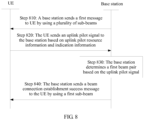
- FIG. 8 is a diagram of signaling interaction in another beam-based multi-connection communication method. As shown in FIG. 8 , the method may include the following steps.
- Step 810 A base station sends a first message to UE by using a first beam, where the first message may include uplink reference signal resource information and indication information, and the indication information is used to indicate an uplink reference signal resource used by one or more beams of the UE.
- the uplink reference signal may be an uplink pilot signal, and the uplink pilot signal is usually used by the base station to estimate an uplink channel, evaluate uplink channel quality, or demodulate uplink data. That is, the base station configures an uplink reference signal resource for each beam connection.
- the first message may be an RRC message, for example, an RRC configuration message.
- the uplink reference signal is an uplink pilot signal.
- the indication information may be corresponding to beam connection index information, that is, the indication information explicitly indicates an uplink pilot resource used by each beam connection.
- the indication information may indicate, by using a configuration sequence of an uplink pilot resource (an occurrence sequence in a configuration message), an uplink pilot resource used by each beam connection.
- the configuration sequence of the uplink pilot resource is set to be corresponding to an index number of a current beam connection, that is, an uplink pilot resource 1 is corresponding to a beam connection 1, and so on, so as to indicate the uplink pilot resource used by each beam connection. It may be understood that a beam connection established between the UE and the base station needs to meet channel reciprocity.
- uplink pilot resource needs to be continuously allocated to the UE for use.
- the uplink pilot resource may be periodically allocated, or may be aperiodically allocated.
- the base station needs to configure an uplink pilot resource for the UE, for example, a channel sounding reference signal (SRS) pilot resource.
- SRS channel sounding reference signal
- the base station may obtain indication information by configuring sounding reference signal uplink configuration dedicated information (for example, sounding reference signal uplink config dedicated information element, Sounding RS-UL-ConfigDedicated IE) in an RRC message. If the uplink pilot resource is aperiodic configured, the base station may obtain indication information by configuring SoundingRS-UL-ConfigDedicatedAperiodic-r10 IE information in an RRC message.
- sounding reference signal uplink configuration dedicated information for example, sounding reference signal uplink config dedicated information element, Sounding RS-UL-ConfigDedicated IE
- the base station may allocate a plurality of independent uplink pilot resources to the UE.
- Each beam connection uses a different pilot resource, that is, one independent uplink pilot resource is scheduled for an uplink beam in one beam connection.
- the base station may allocate one uplink pilot resource to the UE, so that the UE determines, based on indication information, that the uplink pilot resource is scheduled for uplink beams in a plurality of beam connections in a time division multiplexing manner.
- the base station configures time division multiplexing indication information in an RRC message, to instruct the uplink beams in the plurality of beam connections to circularly and successively use the uplink pilot resource in a time sequence; or the base station may configure a time division multiplexing correspondence, to instruct the uplink beams in the plurality of beam connections to use the uplink pilot resource.
- the base station may allocate one uplink pilot resource to the UE, so that the UE determines, based on indication information, that the pilot resource is scheduled for all uplink beams in a plurality of beam connections in a spatial multiplexing manner.
- the base station configures spatial multiplexing indication information in an RRC message, to instruct to schedule the pilot resource for all the uplink beams in the plurality of beam connections in a spatial multiplexing manner. This manner is applicable to only a case in which no interference exists between beams or interference is extremely small.
- the uplink reference signal resource is sent to the UE by using a beam, of the base station, in a beam connection.
- Step 820 The UE sends an uplink reference signal to the base station based on the uplink reference signal resource information and the indication information by using a first beam.
- the UE sends the uplink reference signal to the base station based on the uplink reference signal resource information by using the first beam in a first beam connection.
- Step 830 The base station determines a first beam pair based on the uplink reference signal, where the first beam pair includes the first beam of the UE and a first sub-beam of the first beam of the base station.
- the uplink reference signal is an uplink pilot signal.
- the base station After performing channel estimation on the first beam of the UE based on the uplink pilot signal, the base station calculates transmission weights corresponding to the plurality of sub-beams.
- the transmission weight is a direction adjustment amount.
- the base station adjusts a transmission direction of the sub-beam based on the transmission weight, to determine the first sub-beam (optimal beam) that matches the first beam of the UE and determine the first beam pair, and sends downlink data to the UE by using the first sub-beam, to replace the first beam connection established between the UE and the base station.
- the first beam pair includes the first beam of the UE and the first sub-beam of the base station, and the first beam connection includes the first beam of the UE and the first beam of the base station.
- the base station may determine the first beam pair according to a connection criterion that signal quality is greater than a preset threshold.
- the base station may determine the first beam pair in another manner.
- Step 840 The base station sends a beam connection establishment success message to the UE by using the first sub-beam, to select a beam of the base station.
- the beam establishment success message may include the to-be-sent data information, so that the UE exchanges information with the base station.
- the UE may further select a dedicated message beam from a range of each of the plurality of common message beam by using a measurement result of an uplink reference signal or a measurement result of a downlink reference signal.
- the UE further establishes a beam connection to the dedicated message beam based on different pilot resources (a plurality of pilot resources) that are corresponding to different beam connections and that are allocated by the base station to each UE, or one pilot resource (which is used through time division multiplexing or spatial multiplexing) corresponding to different beam connections, so as to implement dedicated communication between the UE and the base station.
- the base station chooses to delete at least one beam connection, to prevent communication between the UE and the base station from being blocked.
- the to-be-deleted at least one beam connection may be a beam connection with relatively poor signal quality.
- the UE or the base station chooses to delete at least one beam connection.
- the to-be-deleted beam connection may be a beam connection between the UE and a sub-beam (dedicated message beam) of the base station, or may be a beam connection between the UE and a common message beam of the base station.
- deleting a beam connection means that the UE no longer listens to a downlink message sent by the base station in the beam connection.
- FIG. 9 is a diagram of signaling interaction in still another beam-based multi-connection communication method. As shown in FIG. 9 , the method may include the following steps.
- Step 910 A base station sends reference signals to UE by using a plurality of transmit beams.
- the reference signal may be a synchronization signal or another downlink pilot signal.
- the synchronization signal is used by the UE to obtain downlink synchronization.
- the UE can correctly obtain an indication message of the base station only after obtaining downlink synchronization, for example, the indication message is an uplink resource allocated to the UE for transmitting data or control signaling.
- the downlink pilot signal is usually used by the UE to estimate a downlink channel, evaluate downlink channel quality, or demodulate downlink data.
- the reference signal is a synchronization signal.
- the base station sends synchronization signals to the UE by using the plurality of transmit beams, that is, one transmit beam transmits one synchronization signal.
- the synchronization signals transmitted by the transmit beams may be the same or different.
- each beam may have a separate reference signal specially used for channel estimation.
- Step 920 The UE measures signal quality of the plurality of beams of the base station based on the reference signals, and obtains measurement results.
- the UE receives the reference signal sent by each of the plurality of beams of the base station, and performs channel estimation on the plurality of beams of the base station, to obtain attribute information of the plurality of beams, such as signal quality information.
- the terminal UE measures the signal quality of the plurality of beams of the base station based on the attribute information, and obtains the measurement results.
- the process in which the UE measures the plurality of beams of the base station may be periodic, or may be triggered by the base station. Preferably, considering accuracy and real-time quality of measurement, the UE periodically measures the plurality of beams of the base station.
- Step 930 The UE sends a measurement report to the base station, where the measurement report may include signal quality information of the plurality of beams of the base station.
- Step 940 The base station determines, based on the measurement report, a to-be-deleted first beam connection from a beam connection connected between the base station and the UE.
- the base station determines, based on the measurement results, the to-be-deleted first beam connection from the beam connection connected between the base station and the UE. It may be understood that the to-be-deleted first beam connection may have signal quality lower than a preset threshold, and may also cause excessively high power consumption of the UE.
- Step 950 The base station sends a first message to the UE, where the first message includes information instructing to delete the first beam connection, to instruct the UE to delete the first beam connection.
- the first message may be an RRC message, a PDCCH order message, or a MAC CE message.
- the information that instructs to delete the first beam connection and that is in the first message may be obtained in the following manners:
- the first message may further include index information of the to-be-deleted first beam connection.
- the base station may send the firstmessage by using a beam connection (a second beam connection) other than the first beam connection, and add the index information of the first beam connection to the first message.
- Step 960 The UE deletes the first beam connection based on the information instructing to delete the first beam connection.
- Step 970 The UE sends an acknowledgement (ACK) message to the base station, and completes a deletion operation.
- ACK acknowledgement
- the UE may send the measurement report to the base station.
- the base station determines, based on the measurement report, the to-be-deleted first beam connection from the beam connection connected between the base station and the UE, the UE receives the first message sent by the base station, and the UE deletes the first beam connection based on the first message. After deleting the first beam connection, the UE no longer listens to a downlink message sent by the base station, thereby improving quality of communication between the base station and the UE.
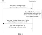
- FIG. 10 is a diagram of signaling interaction in still another beam-based multi-connection communication method. As shown in FIG. 10 , the method may include the following steps.
- Step 1010 UE sends a delete request message to a base station, where the delete request message includes index information of a to-be-deleted first beam connection or index information of a first beam of the base station side.
- the UE When the UE detects that signal quality of the first beam connection is poor or power consumption of the first beam connection is relatively large, the UE sends the delete request message to the base station, to instruct to delete the first beam connection.
- the UE sends the delete request message to the base station by using the first beam connection, to instruct to delete the current beam connection.
- the UE may send the delete request message by using a beam connection (a second beam connection) other than the first beam connection, and add the index information of the first beam connection to the delete request message.
- Step 1020 The base station determines, based on the delete request message, the to-be-deleted first beam connection from a beam connection connected between the base station and the UE.
- the base station determines, based on the index information of the to-be-deleted first beam connection or the index information of the first beam of the base station side, the to-be-deleted first beam connection from the beam connection connected between the base station and the UE.
- Step 1030 After the base station determines the to-be-deleted first beam connection, the base station sends a delete acknowledgement message to the UE, where the delete acknowledgement message includes information instructing to delete the first beam connection, to instruct the UE to delete the first beam connection.
- Step 1040 The UE sends an ACK message to the base station, and completes a deletion operation.
- the UE may send the delete request message to the base station.
- the base station determines, based on the delete request message, the to-be-deleted first beam connection from the beam connection connected between the base station and the UE, the UE receives the delete acknowledgement message sent by the base station, and the UE deletes the first beam connection based on the delete acknowledgement message. In this way, quality of communication between the base station and the UE is improved.
- the UE or the base station performs a replacement operation, that is, deletes an established beam connection and adds a new beam connection. In this case, a random access process is initiated for the new beam pair.
- the replacement operation may be understood as follows: The UE no longer listens, by using the second beam connection established to the base station, a downlink message sent by the base station, and instead, listens, by using the first beam connection, to the downlink message sent by the base station.
- FIG. 11 is a diagram of signaling interaction in beam connection replacement. As shown in FIG. 11 , the method may include the following steps.
- Step 1110 A base station sends a reference signal to UE by using each of a plurality of beams.
- the reference signal may be a synchronization signal or a pilot signal.
- Step 1120 The UE measures signal quality of the plurality of beams of the base station based on the reference signals, and determines a first beam pair based on measurement results.
- the UE periodically measures the plurality of beams that are on the base station side and that are in an unconnected state.
- the UE determines the first beam pair based on the measurement results.
- Signal quality of a first beam connection formed by using the first beam pair is higher than that of a second beam connection, and the second beam connection may be a beam connection that has worst signal quality or largest power consumption in beam connections established between the UE and the base station.
- the signal quality of the first beam connection formed by using the first beam pair is higher than that of the second beam connection established between the UE and the base station.
- the UE may also determine the first beam pair in another manner in step 1110 and step 1120.
- Step 1130 The UE sends a first message to the base station, where the first message includes identification information of the UE and beam connection establishment request information.
- the UE sends the first message to the base station by using a first beam.
- the first beam is a beam in the first beam pair, and the first beam is a. beam used by the UE.
- the first message may be an RRC message or a MAC CE message
- the identification information of the UE may be a cell radio network temporary identifier (C-RNTI).
- C-RNTI cell radio network temporary identifier
- the MAC CE message when the first message is a MAC CE message, the MAC CE message includes a message subheader part and a payload part.
- the UE may reconfigure a value of a logical channel identifier (LCID) in a MAC CE subheader structure, to indicate beam connection establishment request information, beam connection establishment acknowledgement information, beam connection establishment rejection information, or the like; or the UE may reconfigure a payload structure of the MAC CE message, to indicate beam connection establishment request information, beam connection establishment acknowledgement information, beam connection establishment rejection information, or the like.
- LCID logical channel identifier
- a structure of the MAC CE subheader part may include an R field of one reserved bit, a 1-bit F2 field, a 1-bit E field, and a 5-bit LCID field.
- F2 is a format field and is used to indicate a length of a length field.
- E is an extended field, and the extended field is a flag bit used to indicate whether another field exists in a MAC header.
- the UE may select an LCID value corresponding to each of index values 01011 to 11000, to indicate beam connection establishment request information, beam connection establishment acknowledgement information, beam connection establishment rejection information, or the like. A specific correspondence is stipulated in a protocol.
- a structure of the MAC CE payload part may include two reserved R bits and a newly added 6-bit beam index bit.
- the UE may increase or decrease a quantity of R bits, to indicate beam connection establishment request information, beam connection establishment acknowledgement information, beam connection establishment rejection information, or the like.
- the beam index bit indicates an index of a beam to be connected to. It should be noted that according to a communication requirement, the quantity of R bits in the MAC CE payload part may be any number ranging from 0 to 7. For example, if the quantity of R bits is 2 (that is, there are two R bits), the beam index bit is 6 bits.
- FIG. 12 and FIG. 13 may be used according to a design requirement, or another configuration process may be used according to a design requirement. This is not limited in the present invention.
- the UE may add indication information to the RRC message.
- the indication information is used to indicate beam connection establishment request information, beam connection establishment acknowledgement information, beam connection establishment rejection information, or the like.
- the first message may further include index information of the to-be-replaced second beam connection, that is, the UE requests the base station to delete the established second beam connection.
- Step 1140 After the base station determines, based on the identification information of the UE, that a quantity of beam connections between the base station and the UE reaches a connection threshold, the base station sends a first response message based on the beam connection establishment request information, where the first response message includes beam connection replacement indication information.
- the base station determines, by identifying a C-RNTI, the UE that requests a beam connection, and determines whether a current quantity of beam connections of the UE reaches the maximum connection threshold.
- the base station When the quantity of beam connections of the UE reaches the maximum connection threshold, the base station sends the first response message to the UE based on the beam connection establishment request information by using a first beam of the base station.
- the first response message may include the beam replacement indication information.
- the replacement indication information is used to instruct the UE to delete the established second beam connection, and establish a current beam connection, that is, the first beam connection formed by using the first beam pair.
- the base station When the quantity of beam connections of the UE reaches the maximum connection threshold, the base station sends the first response message to the UE by using an established beam connection other than the second beam connection.
- the first response message may include the beam replacement indication information and the index information of the to-be-replaced second beam connection or index information of a second beam, of the base station side, in the second beam connection.
- the base station sends the first response message to the UE by identifying the C-RNT, the beam establishment connection request information, and the index information of the to-be-replaced second beam connection.
- the first response message includes the beam replacement indication information.
- Step 1150 The UE replaces, based on the beam connection replacement indication information, a second beam connection with a first beam connection formed by using the first beam pair.
- step 1151 is performed: The UE sends a random access preamble message to the base station by using a first beam.
- Step 1152 The base station sends a random access response message to the UE based on the random access preamble message by using a first beam.
- the UE based on a multi-beam connection between the base station and the UE, the UE obtains the first beam, of the base station, that is not connected to. After the UE determines, from a plurality of first beams of the UE, a second beam that matches the first beam (that is, forms a beam pair), the UE sends, to the base station by using the second beam, the first message carrying the identification information of the UE and the beam establishment request information.
- the UE When the base station determines, based on the identification information of the UE, that the quantity of beam connections between the base station and the UE reaches the connection threshold, the UE receives the first response message that is sent by the base station based on the beam establishment request information and that carries the beam replacement indication information. The UE replaces the second beam connection with the first beam connection based on the beam replacement indication information.
- the second beam connection is a beam connection established between the UE and the base station, and the first beam connection includes the second beam of the UE and the first beam of the base station. In this way, normal communication between the base station and the UE is improved.
- an embodiment of the present invention further provides a terminal.
- a terminal may include a processing unit 1210, a receiving unit 1220, and a sending unit 1230.
- the processing unit 1210 is configured to establish a communication connection to a first sub-beam of a network device (for example, a base station) by using a first beam in a plurality of beams.
- a network device for example, a base station
- the receiving unit 1220 is configured to receive, by using the first beam, downlink reference signals sent by a plurality of sub-beams of the base station.
- the processing unit 1210 is further configured to: measure signal quality of the plurality of sub-beams of the base station based on the downlink reference signals, and determine a first beam pair based on measurement results, where the first beam pair includes the first beam of the terminal and the first sub-beam of the base station.
- the sending unit 1230 is configured to send attribute information of the first sub-beam to the base station by using the first beam, so that the base station determines the first sub-beam based on the attribute information of the first sub-beam, and the base station establishes, by using the first sub-beam, a communication connection to the first beam used by the terminal.
- the sending unit 1230 is further configured to send attribute information of the plurality of sub-beams to the base station, so that the base station determines the first sub-beam based on the attribute information of the plurality of sub-beams, and the base station establishes, by using the first sub-beam, a communication connection to the first beam used by the terminal.
- the sending unit 1230 is further configured to send an uplink reference signal to the base station by using the first beam, so that the base station determines a first beam pair based on the uplink reference signal, where the first beam pair includes the first beam of the terminal and the first sub-beam of the base station, so that the processing unit 1210 establishes a beam connection to the first sub-beam by using the first beam.
- the receiving unit 1220 is further configured to receive, by using the first beam, a first message sent by the base station, where the first message includes uplink reference signal resource information and first indication information, and the first indication information is used to indicate an uplink reference signal resource used by one or more beams of the terminal.
- the sending unit 1230 is further configured to send the uplink reference signal to the base station based on the uplink reference signal resource information and the first indication information by using the plurality of beams.
- Functions of the units of the terminal may be implemented by performing the steps in FIG. 7A and FIG. 7B . Therefore, a specific working process of the terminal provided in the foregoing embodiment is not described herein again.
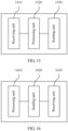
- an embodiment further provides a base station.
- a base station may include a processing unit 1310, a receiving unit 1320, and a sending unit 1330.
- the processing unit 1310 is configured to establish a communication connection to a first beam of a terminal by using a first sub-beam, where the first sub-beam is a sub-beam of a first beam in a plurality of beams of the base station.
- the sending unit 1330 is configured to send downlink reference signals to the terminal by using a plurality of sub-beams, so that the terminal measures signal quality of the plurality of sub-beams of the base station based on the downlink reference signals, and determines a first beam pair based on measurement results, where the first beam pair includes the first beam of the terminal and the first sub-beam of the first beam of the base station.
- the receiving unit 1320 is configured to receive, by using the first beam, attribute information that is of the first sub-beam and that is sent by the terminal.
- the processing unit 1310 determines the first sub-beam based on the attribute information of the first sub-beam.
- the receiving unit 1320 is further configured to receive, by using the first beam, attribute information of the plurality of sub-beams that is sent by the terminal.
- the processing unit 1310 is further configured to: determine the first sub-beam based on the attribute information of the plurality of sub-beams, and establish a communication connection to the first beam of the terminal by using the first sub-beam.
- the receiving unit 1320 is further configured to receive, by using the first beam, an uplink reference signal sent by the terminal.
- the processing unit 1310 is further configured to determine a first beam pair based on the uplink reference signal, so that the processing unit 1310 establishes a communication connection to the first beam of the terminal by using the first sub-beam, where the first beam pair includes the first beam of the terminal and the first sub-beam of the base station.
- the sending unit 1330 is further configured to send a first message to the terminal by using the first beam, where the first message includes uplink reference signal resource information and first indication information, and the first indication information is used to indicate an uplink reference signal resource used by one or more beams of the terminal.
- the receiving unit 1320 is further configured to receive, by using the first beam, the uplink reference signal sent by the terminal based on the uplink reference signal resource information and the first indication information.
- the processing unit 1310 is further configured to allocate at least one uplink reference signal resource to the terminal that has a multi-beam connection.
- Functions of the units of the base station may be implemented by performing the steps in FIG. 8 . Therefore, a specific working process of the base station provided in the foregoing embodiment is not described herein again.
- an embodiment further provides a terminal.
- FIG. 14 shows another terminal according to an embodiment of the present invention.
- the terminal may include a sending unit 1410 and a receiving unit 1420.
- the sending unit 1410 is configured to send a first message to a base station. After the base station determines, based on the first message, a to-be-deleted first beam connection from a beam connection connected between the base station and the terminal, the receiving unit 1420 is configured to receive a second message sent by the base station, where the second message includes information instructing to delete the first beam connection, to instruct to delete the first beam connection.
- the terminal may further include a processing unit 1430.
- the first message is a measurement report, and the measurement report includes measurement results of signal quality of a plurality of beams of the base station.
- the receiving unit 1420 receives the second message sent by the base station.
- the second message includes the information instructing to delete the first beam connection.
- the processing unit 1430 is configured to delete the first beam connection based on the information instructing to delete the first beam connection, so that the receiving unit 1420 no longer listens to a downlink message sent by the base station by using the first beam connection.
- the receiving unit 1420 is further configured to receive, by using a plurality of beams, reference signals sent by the plurality of beams of the base station.
- the processing unit 1430 is further configured to measure the signal quality of the plurality of beams of the base station based on the reference signals.
- the sending unit 1410 is further configured to send the measurement report to the base station, where the measurement report includes the measurement results of the signal quality of the plurality of beams of the base station.
- the receiving unit 1420 is specifically configured to: receive, by using a first beam, the second message sent by the base station, where the first beam is a beam in a first beam pair in the first beam connection, and the first beam is a beam used by the terminal; or receive, by using a second beam other than a first beam of the terminal, the second message sent by the base station.
- the second message further includes index information of the to-be-deleted first beam connection.
- the processing unit 1430 is specifically configured to delete the first beam connection based on the information instructing to delete the first beam connection and the index information of the to-be-deleted first beam connection.
- the first message is a delete request message
- the delete request message includes index information of the to-be-deleted first beam connection or index information of a first beam of the base station.
- the receiving unit receives the second message sent by the base station.
- Functions of the units of the terminal may be implemented by performing the steps in FIG. 9 and FIG. 10 . Therefore, a specific working process of the terminal provided in the foregoing embodiment is not described herein again.
- an embodiment further provides a base station.
- FIG. 15 shows another base station according to an embodiment of the present invention.
- the base station may include a receiving unit 1510, a processing unit 1520, and a sending unit 1530.
- the receiving unit 1510 is configured to receive, by using a plurality of beams, a first message sent by a terminal.
- the processing unit 1520 is configured to determine, based on the first message, a to-be-deleted first beam connection from a beam connection connected between the base station and the terminal.
- the sending unit 1530 is configured to send a second message to the terminal, where the second message includes information instructing to delete the first beam connection, to instruct to delete the first beam connection.
- the first message is a measurement report
- the measurement report includes measurement results of signal quality of the plurality of beams of the base station.
- the processing unit 1520 is specifically configured to determine, based on the measurement results, the to-be-deleted first beam connection from the beam connection connected between the base station and the terminal.
- the sending unit 1530 is further configured to send reference signals to the terminal by using the plurality of beams, so that the terminal measures the signal quality of the plurality of beams of the base station based on the reference signals.
- the receiving unit 1510 is further configured to receive, by using the plurality of beams, the measurement report sent by the terminal, where the measurement report includes the measurement results of the signal quality of the plurality of beams of the base station.
- the second message further includes index information of the to-be-deleted first beam connection, so that the terminal deletes the first beam connection based on the information instructing to delete the first beam connection and the index information of the to-be-deleted first beam connection, and the terminal no longer listens to a downlink message sent by the base station by using the first beam connection.
- the first message is a delete request message
- the delete request message includes index information of the to-be-deleted first beam connection or index information of a first beam of the base station.
- the processing unit 1520 is specifically configured to determine, based on the index information of the to-be-deleted first beam connection or the index information of the first beam of the base station, the to-be-deleted first beam connection from the beam connection connected between the base station and the terminal.
- Functions of the units of the base station may be implemented by performing the steps in FIG. 9 and FIG. 10 . Therefore, a specific working process of the base station provided in the foregoing embodiment is not described herein again.
- an embodiment further provides a terminal.
- FIG. 16 shows still another terminal according to an embodiment of the present invention.
- the terminal includes a processing unit 1610, a sending unit 1620, and a receiving unit 1630.
- the processing unit 1610 is configured to determine a first beam pair.
- the sending unit 1620 is configured to send a first message to a base station, where the first message includes identification information of the terminal and beam connection establishment request information.
- the receiving unit 1630 is configured to receive a first response message sent by the base station based on the beam connection establishment request information, where the first response message includes beam connection replacement indication information.
- the processing unit 1610 is further configured to replace, based on the beam connection replacement indication information, a second beam connection with a first beam connection formed by using the first beam pair, so that the receiving unit 1630 no longer listens to a downlink message sent by the base station by using the second beam connection, and instead, listens, by using the first beam connection, to the downlink message sent by the base station, where the second beam connection is a beam connection established between the terminal and the base station.
- the receiving unit 1630 is further configured to receive, by using each beam, a reference signal sent by the base station by using each of a plurality of beams.
- the processing unit 1610 is further configured to: measure signal quality of the plurality of beams of the base station based on the reference signals, and determine the first beam pair based on measurement results, where signal quality of the first beam connection formed by using the first beam pair is higher than that of the second beam connection.
- the sending unit 1620 is specifically configured to send the first message to the base station by using a first beam, where the first beam is a beam in the first beam pair, and the first beam is a beam used by the terminal.
- the first response message further includes index information of the to-be-replaced second beam connection.
- the processing unit 1610 is specifically configured to replace, based on the beam connection replacement indication information and the index information of the second beam connection, the second beam connection with the first beam connection formed by using the first beam pair.
- the sending unit 1620 before the sending unit 1620 sends the first message to the base station, the sending unit 1620 is further configured to send a random access preamble message to the base station by using the first beam.
- the receiving unit 1630 is further configured to receive, by using the first beam, a random access response message sent by the base station based on the random access preamble message.
- Functions of the units of the terminal may be implemented by performing the steps in FIG. 11 . Therefore, a specific working process of the terminal provided in the foregoing embodiment is not described herein again.
- an embodiment further provides a base station.
- FIG. 17 shows still another base station according to an embodiment of the present invention.
- the base station includes a receiving unit 1710, a sending unit 1720, and a processing unit 1730.
- the receiving unit 1710 is configured to receive a first message sent by the terminal after the terminal determines a first beam pair, where the first message includes identification information of the terminal and beam connection establishment request information.
- the sending unit 1720 sends a first response message based on the beam connection establishment request information, where the first response message includes beam connection replacement indication information, so that the terminal replaces, based on the beam connection replacement indication information, a second beam connection with a first beam connection formed by using the first beam pair, and the terminal no longer listens to a downlink message sent by the sending unit by using the second beam connection, and instead, listens, by using the first beam connection, to the downlink message sent by the sending unit 1720, where the second beam connection is a beam connection established between the terminal and the base station.
- the sending unit 1720 is further configured to send a reference signal to the terminal by using each of a plurality of beams, so that the terminal determines the first beam pair based on the reference signal, where signal quality of the first beam connection formed by using the first beam pair is higher than that of the second beam connection.
- the first response message further includes index information of the to-be-replaced second beam connection, so that the terminal replaces, based on the beam replacement indication information and the index information of the second beam connection, the second beam connection with the first beam connection formed by using the first beam pair.
- the receiving unit 1710 before the receiving unit 1710 receives the first message sent by the terminal, the receiving unit 1710 is further configured to receive, by using a first beam, a random access preamble message sent by the terminal.
- the sending unit 1720 is further configured to send a random access response message to the terminal based on the random access preamble message by using the first beam.
- Functions of the units of the base station may be implemented by performing the steps in FIG. 11 . Therefore, a specific working process of the base station provided in the foregoing embodiment is not described herein again.
- an embodiment of the present invention further provides still another terminal.
- the terminal includes a transmitter 1801, a receiver 1802, a processor 1803, and a modem processor 1805.
- the transmitter 1801 adjusts an output sample and generates an uplink signal.
- the uplink signal is transmitted to the base station in the foregoing embodiment by using an antenna.
- the transmitter 1801 performs steps of communication between the terminal and the base station in FIG. 7A to FIG. 11 .
- the antenna receives a downlink signal transmitted by the base station in the foregoing embodiment.
- the receiver 1802 adjusts the signal received from the antenna and provides an input sample, for example, performs the steps of communication between the terminal and the base station in FIG. 7A to FIG. 11 .
- an encoder 1806 receives service data and a signaling message that are to be sent in an uplink, and processes (for example, formats, encodes, and interleaves) the service data and the signaling message.
- a modulator 1807 further processes (for example, performs symbol mapping on and modulates) encoded service data and an encoded signaling message, and provides an output sample.
- a demodulator 1809 processes (for example, demodulates) the input sample, and provides symbol estimation.
- a decoder 1808 processes (for example, de-interleaves and decodes) the symbol estimation, and provides decoded data and a decoded signaling message that are sent to the terminal.
- the encoder 1806, the modulator 1807, the demodulator 1809, and the decoder 1808 is implemented by the composite modem processor 1805. These foregoing components perform processing based on a radio access technology (for example, access technologies in LTE, 5G, and other evolved systems) used by the base station.
- a radio access technology for example, access technologies in LTE, 5G, and other evolved systems
- the terminal further includes: a memory 1804, configured to store program code and data that are used for the terminal; and a processor 1803, configured to control and manage an action of the terminal, and perform processing performed by the terminal in the foregoing embodiment, for example, perform steps 720, 760, 920, 960, 1120, and 1150 in FIG. 7A , FIG. 7B , FIG. 9 , and FIG. 11 .
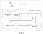
- an embodiment of the present invention further provides still another base station.
- the base station includes a transceiver 1910 and a processor 1920.
- the transceiver 1910 is configured to support information receiving and transmission between the base station and the terminal in the foregoing embodiment, and support wireless communication between the terminal and another terminal.
- the transceiver 1910 includes a transmitter 1911 and a receiver 1912.
- the processor 1920 performs various functions, in FIG. 7A to FIG. 10 , used to communicate with the terminal.
- an uplink an uplink signal from the terminal is received by using an antenna, is demodulated by the transceiver 1910, and is further processed by the processor 1920 to restore service data and signaling information sent by the terminal.
- service data and a signaling message are processed by the processor 1920, such as step 940 in FIG. 9 , and are demodulated by the transceiver 1910 to generate a downlink signal, and the downlink signal is transmitted to the terminal by using an antenna.
- the base station further includes: a memory 1930, configured to store program code and data of the base station; and a communications unit 1940, configured to support communication between the base station and another network entity, for example, support communication between the base station and another communications network entity such as a core network.
- a memory 1930 configured to store program code and data of the base station
- a communications unit 1940 configured to support communication between the base station and another network entity, for example, support communication between the base station and another communications network entity such as a core network.
- the processor used to perform functions of the foregoing base station and terminal in the present invention may be a central processing unit (CPU), a general purpose processor, a digital signal processor (DSP), an application-specific integrated circuit (ASIC), a field programmable gate array (FPGA) or another programmable logic device, a transistor logic device, a hardware component, or any combination thereof.
- the processor may implement or execute various example logical blocks, modules, and circuits described with reference to content disclosed in the present invention.
- the processor may be a combination of processors implementing a computing function, for example, a combination of one or more microprocessors, or a combination of a DSP and a microprocessor.
- the memory may be a volatile memory, for example, a random access memory (RAM); or may be a nonvolatile memory, for example, a read-only memory (ROM), a flash memory, a hard disk drive (HDD), or a solid-state drive (SSD); or may be a combination of the foregoing types of memories.
- RAM random access memory
- ROM read-only memory
- HDD hard disk drive
- SSD solid-state drive
- Steps of methods or algorithms described in the embodiments disclosed in this specification may be implemented by hardware, a software module executed by a processor, or a combination thereof.
- the software instruction may include a corresponding software module.
- the software module may be stored in a random access memory, a flash memory, a read-only memory, an erasable programmable read only memory (EPROM), an electrically erasable programmable read-only memory (EEPROM), a hard disk, a compact disc read-only memory (CD-ROM), or any other form of storage medium well-known in the art.
- storage medium is coupled to a processor, so that the processor can read information from the storage medium or write information into the storage medium.
- the storage medium may be a component of the processor.
- the processor and the storage medium may be located in the ASIC.
- the ASIC may be located in user equipment.
- the processor and the storage medium may exist in the user equipment as discrete components.
Landscapes
- Engineering & Computer Science (AREA)
- Computer Networks & Wireless Communication (AREA)
- Signal Processing (AREA)
- Mobile Radio Communication Systems (AREA)
Claims (6)
- Procédé de communication multiconnexion basé sur un faisceau, dans lequel un dispositif terminal communique avec et se connecte à un dispositif de réseau en utilisant une pluralité de faisceaux, et le procédé comprend :l'établissement, par le dispositif terminal, d'une connexion de communication avec un premier sous-faisceau du dispositif de réseau en utilisant un premier faisceau dans la pluralité de faisceaux ;dans lequel le premier sous-faisceau est un faisceau de message dédié ; caractérisé en ce queavant l'établissement, par le dispositif terminal, d'une connexion de communication avec un premier sous-faisceau du dispositif de réseau en utilisant un premier faisceau, le procédé comprend en outre :la réception, (710) par le dispositif terminal en utilisant le premier faisceau, des signaux de référence de liaison descendante envoyés par une pluralité de sous-faisceaux du dispositif de réseau ;la mesure, par le dispositif terminal, de la qualité de signal de la pluralité de sous-faisceaux du dispositif de réseau sur la base des signaux de référence de liaison descendante ;la détermination (720), par le dispositif terminal, d'une première paire de faisceaux sur la base des résultats de mesure, dans lequel la première paire de faisceaux comprend le premier faisceau du dispositif terminal et le premier sous-faisceau du dispositif de réseau ; etl'envoi (730), par le dispositif terminal, d'informations d'attribut du premier sous-faisceau au dispositif de réseau en utilisant le premier faisceau, dans lequel les informations d'attribut du premier sous-faisceau sont utilisées par le dispositif de réseau pour déterminer (740) le premier sous-faisceau, et établir (750), en utilisant le premier sous-faisceau, une connexion de communication avec le premier faisceau utilisé par le dispositif terminal.
- Procédé selon la revendication 1, dans lequel
avant l'établissement, par le dispositif terminal, d'une connexion de communication avec un premier sous-faisceau du dispositif de réseau en utilisant un premier faisceau, le procédé comprend en outre :la réception, par le dispositif terminal en utilisant le premier faisceau, de signaux de référence de liaison descendante envoyés par une pluralité de sous-faisceaux du dispositif de réseau ;la mesure, par le dispositif terminal, de la qualité de signal de la pluralité de sous-faisceaux du dispositif de réseau sur la base des signaux de référence de liaison descendante ; etl'envoi, par le dispositif terminal, d'informations d'attribut de la pluralité de sous-faisceaux au dispositif de réseau en utilisant le premier faisceau, dans lequel les informations d'attribut de la pluralité de sous-faisceaux sont utilisées par le dispositif de réseau pour déterminer le premier sous-faisceau, et établir, en utilisant le premier sous-faisceau, une connexion de communication avec le premier faisceau utilisé par le dispositif terminal. - Procédé de communication multiconnexion basé sur un faisceau, dans lequel un dispositif de réseau communique avec et se connecte à un dispositif terminal en utilisant une pluralité de faisceaux, et le procédé comprend :l'établissement, par le dispositif de réseau, d'une connexion de communication avec un premier faisceau du dispositif terminal en utilisant un premier sous-faisceau, dans lequel le premier sous-faisceau est un sous-faisceau d'un premier faisceau dans la pluralité de faisceaux du dispositif de réseau ;dans lequel le premier sous-faisceau est un faisceau de message dédié ; caractérisé en ce queavant l'établissement, par le dispositif de réseau, d'une connexion de communication avec un premier faisceau du dispositif terminal en utilisant un premier sous-faisceau, le procédé comprend en outre :l'envoi, (710) par le dispositif de réseau, de signaux de référence de liaison descendante au dispositif terminal en utilisant une pluralité de sous-faisceaux, de sorte que le dispositif terminal mesure la qualité de signal de la pluralité de sous-faisceaux du dispositif de réseau sur la base des signaux de référence de liaison descendante, et détermine (720) une première paire de faisceaux sur la base des résultats de mesure, dans lequel la première paire de faisceaux comprend le premier faisceau du dispositif terminal et le premier sous-faisceau du premier faisceau du dispositif de réseau ;la réception (730), par le dispositif de réseau en utilisant le premier faisceau, d'informations d'attribut qui appartiennent au premier sous-faisceau et qui sont envoyées par le dispositif terminal, et la détermination du premier sous-faisceau sur la base des informations d'attribut du premier sous-faisceau ; ou la réception, par le dispositif de réseau en utilisant le premier faisceau, d'informations d'attribut de la pluralité de sous-faisceaux qui sont envoyées par le dispositif terminal, et la détermination (740) du premier sous-faisceau sur la base des informations d'attribut de la pluralité de sous-faisceaux ; etl'établissement, (750) par le dispositif de réseau, d'une connexion de communication avec le premier faisceau du dispositif terminal en utilisant le premier sous-faisceau.
- Dispositif terminal, dans lequel le dispositif terminal communique avec et se connecte à un dispositif de réseau en utilisant une pluralité de faisceaux, et le dispositif terminal comprend une unité de traitement, configurée pour établir une connexion de communication avec un premier sous-faisceau du dispositif de réseau en utilisant un premier faisceau dans la pluralité de faisceaux ;dans lequel le premier sous-faisceau est un faisceau de message dédié ; caractérisé en ce quele dispositif terminal comprend en outre une unité de réception et une unité d'envoi, et l'unité de réception est configurée pour recevoir (710), en utilisant le premier faisceau, des signaux de référence de liaison descendante envoyés par une pluralité de sous-faisceaux du dispositif de réseau ;l'unité de traitement est en outre configurée pour mesurer la qualité de signal de la pluralité de sous-faisceaux du dispositif de réseau sur la base des signaux de référence de liaison descendante ; etla détermination (720) d'une première paire de faisceaux sur la base des résultats de mesure, dans lequel la première paire de faisceaux comprend le premier faisceau du dispositif terminal et le premier sous-faisceau du dispositif de réseau ; etl'unité d'envoi est configurée pour envoyer (730) des informations d'attribut du premier sous-faisceau au dispositif de réseau en utilisant le premier faisceau, dans lequel les informations d'attribut du premier sous-faisceau sont utilisées par le dispositif de réseau pour déterminer (740) le premier sous-faisceau, et établir (750), en utilisant le premier sous-faisceau, une connexion de communication avec le premier faisceau utilisé par le dispositif terminal.
- Dispositif terminal selon la revendication 4, dans lequel le dispositif terminal comprend en outre une unité de réception et une unité d'envoi, et l'unité de réception est configurée pour recevoir, en utilisant le premier faisceau, des signaux de référence de liaison descendante envoyés par une pluralité de sous-faisceaux du dispositif de réseau ;l'unité de traitement est en outre configurée pour mesurer la qualité de signal de la pluralité de sous-faisceaux du dispositif de réseau sur la base des signaux de référence de liaison descendante ; etl'unité d'envoi est configurée pour envoyer des informations d'attribut de la pluralité de sous-faisceaux au dispositif de réseau, dans lequel les informations d'attribut de la pluralité de sous-faisceaux sont utilisées par le dispositif de réseau pour déterminer le premier sous-faisceau, et établir, en utilisant le premier sous-faisceau, une connexion de communication avec le premier faisceau utilisé par le dispositif terminal.
- Dispositif de réseau, dans lequel le dispositif de réseau communique avec et se connecte à un dispositif terminal en utilisant une pluralité de faisceaux, et le dispositif de réseau comprend :
une unité de traitement, configurée pour établir une connexion de communication avec un premier faisceau du dispositif terminal en utilisant un premier sous-faisceau, dans lequel le premier sous-faisceau est un sous-faisceau d'un premier faisceau dans la pluralité de faisceaux du dispositif de réseau :dans lequel le premier sous-faisceau est un faisceau de message dédié ; caractérisé en ce quele dispositif de réseau comprend en outre une unité d'envoi et une unité de réception ;avant que l'unité de traitement n'établisse une connexion de communication avec le premier faisceau du dispositif terminal en utilisant le premier sous-faisceau du premier faisceau,l'unité d'envoi est configurée pour envoyer (710) des signaux de référence de liaison descendante au dispositif terminal en utilisant une pluralité de sous-faisceaux, de sorte que le dispositif terminal mesure la qualité de signal de la pluralité de sous-faisceaux du dispositif de réseau sur la base des signaux de référence de liaison descendante, et détermine (720) une première paire de faisceaux sur la base des résultats de mesure,dans lequel la première paire de faisceaux comprend le premier faisceau du dispositif terminal et le premier sous-faisceau du premier faisceau du dispositif de réseau ;l'unité de réception est configurée pour recevoir (730), en utilisant le premier faisceau, des informations d'attribut qui appartiennent au premier sous-faisceau et qui sont envoyées par le dispositif terminal, et l'unité de traitement détermine le premier sous-faisceau sur la base des informations d'attribut du premier sous-faisceau ; ou l'unité de réception est configurée pour recevoir, en utilisant le premier faisceau, des informations d'attribut de la pluralité de sous-faisceaux qui sont envoyées par le dispositif terminal, et l'unité de traitement détermine (740) le premier sous-faisceau sur la base des informations d'attribut de la pluralité de sous-faisceaux ; etl'unité de traitement établit (750) une connexion de communication avec le premier faisceau du dispositif terminal en utilisant le premier sous-faisceau.
Applications Claiming Priority (2)
| Application Number | Priority Date | Filing Date | Title |
|---|---|---|---|
| CN201610977317.XA CN108377559B (zh) | 2016-11-04 | 2016-11-04 | 基于波束的多连接通信方法、终端设备及网络设备 |
| PCT/CN2017/112934 WO2018082715A1 (fr) | 2016-11-04 | 2017-11-24 | Procédé de communication multiconnexion basé sur un faisceau d'ondes, dispositif terminal, et dispositif de réseau |
Publications (3)
| Publication Number | Publication Date |
|---|---|
| EP3531787A1 EP3531787A1 (fr) | 2019-08-28 |
| EP3531787A4 EP3531787A4 (fr) | 2019-10-02 |
| EP3531787B1 true EP3531787B1 (fr) | 2023-10-11 |
Family
ID=62076610
Family Applications (1)
| Application Number | Title | Priority Date | Filing Date |
|---|---|---|---|
| EP17868407.2A Active EP3531787B1 (fr) | 2016-11-04 | 2017-11-24 | Procédé de communication multiconnexion basé sur un faisceau d'ondes, dispositif terminal, et dispositif de réseau |
Country Status (4)
| Country | Link |
|---|---|
| US (1) | US10972924B2 (fr) |
| EP (1) | EP3531787B1 (fr) |
| CN (1) | CN108377559B (fr) |
| WO (1) | WO2018082715A1 (fr) |
Families Citing this family (16)
| Publication number | Priority date | Publication date | Assignee | Title |
|---|---|---|---|---|
| JP6898448B2 (ja) | 2016-12-09 | 2021-07-07 | テレフオンアクチーボラゲット エルエム エリクソン(パブル) | 分散マッシブmimoのための改良されたアンテナ装置 |
| WO2019076513A1 (fr) | 2017-10-17 | 2019-04-25 | Telefonaktiebolaget Lm Ericsson (Publ) | Synchronisation mimo distribuée |
| EP3714551A1 (fr) | 2017-11-21 | 2020-09-30 | Telefonaktiebolaget LM Ericsson (publ) | Agencement d'antenne amélioré pour mimo massif distribué |
| KR102480041B1 (ko) * | 2018-04-20 | 2022-12-21 | 한국전자통신연구원 | 무선 링크 재설정 방법, 이를 이용하는 무선통신 디바이스 |
| US10778313B2 (en) * | 2018-08-17 | 2020-09-15 | Qualcomm Incorporated | Techniques for beam failure recovery in wireless communications |
| CN110913479B (zh) * | 2018-09-17 | 2022-10-04 | 华为技术有限公司 | 数据通信的方法和装置 |
| CN110971320B (zh) * | 2018-09-28 | 2021-04-30 | 中国移动通信有限公司研究院 | 一种波束质量上报方法、装置、设备及存储介质 |
| US11329699B2 (en) * | 2018-10-16 | 2022-05-10 | Telefonaktiebolaget Lm Ericsson (Publ) | Disturbance mitigation |
| JP7214001B2 (ja) * | 2019-02-22 | 2023-01-27 | ペキン シャオミ モバイル ソフトウェア カンパニー, リミテッド | データ伝送方法、装置及び記憶媒体 |
| CN111698761B (zh) * | 2019-03-15 | 2021-10-22 | 华为技术有限公司 | 通信方法、装置、设备及系统 |
| CN110971384A (zh) * | 2019-11-15 | 2020-04-07 | 深圳职业技术学院 | 一种终端辅助的信息传输方法 |
| CN112994761B (zh) * | 2019-12-12 | 2022-06-07 | 大唐移动通信设备有限公司 | 一种波束确定方法及装置 |
| US11777619B2 (en) | 2020-02-10 | 2023-10-03 | Telefonaktiebolaget Lm Ericsson (Publ) | Dielectric waveguide signal transfer function compensation |
| CN115211175B (zh) * | 2020-03-13 | 2023-10-20 | 华为技术有限公司 | 用于上行传输的方法和装置 |
| US11963188B2 (en) * | 2020-09-21 | 2024-04-16 | Samsung Electronics Co., Ltd. | System and method for beam tracking in a 5G new radio mmWave user equipment |
| CN112804705B (zh) * | 2020-12-30 | 2022-04-01 | 深圳市微网力合信息技术有限公司 | 一种WiFi设备波束方向控制方法、装置及存储介质 |
Family Cites Families (12)
| Publication number | Priority date | Publication date | Assignee | Title |
|---|---|---|---|---|
| US6714760B2 (en) * | 2001-05-10 | 2004-03-30 | Qualcomm Incorporated | Multi-mode satellite and terrestrial communication device |
| US7477597B2 (en) * | 2004-09-08 | 2009-01-13 | Alcatel Lucent | Rural broadband hybrid satellite/terrestrial solution |
| KR101839386B1 (ko) * | 2011-08-12 | 2018-03-16 | 삼성전자주식회사 | 무선 통신 시스템에서의 적응적 빔포밍 장치 및 방법 |
| US20140073337A1 (en) * | 2012-09-11 | 2014-03-13 | Electronics And Telecommunications Research Institute | Communication device and communication method using millimeter-wave frequency band |
| PT2896141T (pt) * | 2012-09-12 | 2020-04-30 | Guangdong Oppo Mobile Telecommunications Corp Ltd | Método num nó de rede, método num equipamento de utilizador, um nó de rede e um equipamento de utilizador para selecionar um candidato de feixe |
| KR20140072968A (ko) * | 2012-12-05 | 2014-06-16 | 한국전자통신연구원 | 이동 통신 시스템에서 다중 연결을 이용한 단말의 핸드오버 방법 |
| JP2015165640A (ja) * | 2014-02-07 | 2015-09-17 | 株式会社Nttドコモ | ユーザ装置、基地局、及び通信方法 |
| US10355761B2 (en) * | 2014-10-07 | 2019-07-16 | Mediatek Inc. | Beam administration methods for cellular/wireless networks |
| JPWO2016084182A1 (ja) * | 2014-11-27 | 2017-08-31 | 富士通株式会社 | 基地局、通信システム及び参照信号送信方法 |
| US20160183232A1 (en) * | 2014-12-19 | 2016-06-23 | Futurewei Technologies, Inc. | System and Method for Interference Coordination in Cellular Millimeter Wave Communications Systems |
| US9955491B2 (en) * | 2014-12-30 | 2018-04-24 | Electronics And Telecommunications Research Institute | Method and apparatus for initial access in mobile communication system |
| US10367677B2 (en) * | 2016-05-13 | 2019-07-30 | Telefonaktiebolaget Lm Ericsson (Publ) | Network architecture, methods, and devices for a wireless communications network |
-
2016
- 2016-11-04 CN CN201610977317.XA patent/CN108377559B/zh active Active
-
2017
- 2017-11-24 WO PCT/CN2017/112934 patent/WO2018082715A1/fr unknown
- 2017-11-24 EP EP17868407.2A patent/EP3531787B1/fr active Active
-
2019
- 2019-05-01 US US16/400,693 patent/US10972924B2/en active Active
Also Published As
| Publication number | Publication date |
|---|---|
| CN108377559B (zh) | 2021-03-30 |
| US20200154291A9 (en) | 2020-05-14 |
| US20190261202A1 (en) | 2019-08-22 |
| US10972924B2 (en) | 2021-04-06 |
| EP3531787A1 (fr) | 2019-08-28 |
| EP3531787A4 (fr) | 2019-10-02 |
| CN108377559A (zh) | 2018-08-07 |
| WO2018082715A1 (fr) | 2018-05-11 |
Similar Documents
| Publication | Publication Date | Title |
|---|---|---|
| EP3531787B1 (fr) | Procédé de communication multiconnexion basé sur un faisceau d'ondes, dispositif terminal, et dispositif de réseau | |
| US11337126B2 (en) | Multi-RAT sidelink communications | |
| US10728823B2 (en) | Methods, devices, and systems for beam refinement during handover | |
| US11800377B2 (en) | Communication system | |
| CN107836086B (zh) | 支持移动性的方法以及用户设备 | |
| US20190246434A1 (en) | Beam-based multi-connection communication method, terminal device, and network device | |
| KR20200057038A (ko) | 사이드링크 통신에서의 캐리어 어그리게이션을 위한 방법 및 장치 | |
| CN110622568B (zh) | 用于系统信息传输的无线电网络节点、无线设备及方法 | |
| CN108633100B (zh) | 随机接入响应的方法和设备以及随机接入的方法和设备 | |
| EP3692758B1 (fr) | Transfert intercellulaire de faisceau à gain élevé | |
| US10383038B2 (en) | Apparatus and methods for providing and receiving system information in a wireless communications network | |
| US9312931B2 (en) | Radio base station, radio terminal, and communication control method | |
| CN113711522A (zh) | 速率匹配模式的有效信令 | |
| KR102612167B1 (ko) | 통신 시스템에서 빔 요소 반송파의 전송 우선순위 결정 방법 및 장치 | |
| WO2024029424A1 (fr) | Système de communication | |
| WO2024029422A1 (fr) | Système de communication | |
| WO2021253422A1 (fr) | Commutation de faisceau pour un équipement utilisateur dans un état inactif avec des autorisations configurées | |
| EP4338312A1 (fr) | Opération simultanée de domaine spatial dans des ressources logicielles d'un noeud iab | |
| CN117336819A (zh) | Ssb传输方法、装置及存储介质 | |
| EP4128991A1 (fr) | Noeud de réseau, équipement utilisateur de dispositif à dispositif, et procédés dans un réseau de radiocommunication |
Legal Events
| Date | Code | Title | Description |
|---|---|---|---|
| STAA | Information on the status of an ep patent application or granted ep patent |
Free format text: STATUS: THE INTERNATIONAL PUBLICATION HAS BEEN MADE |
|
| PUAI | Public reference made under article 153(3) epc to a published international application that has entered the european phase |
Free format text: ORIGINAL CODE: 0009012 |
|
| STAA | Information on the status of an ep patent application or granted ep patent |
Free format text: STATUS: REQUEST FOR EXAMINATION WAS MADE |
|
| 17P | Request for examination filed |
Effective date: 20190520 |
|
| AK | Designated contracting states |
Kind code of ref document: A1 Designated state(s): AL AT BE BG CH CY CZ DE DK EE ES FI FR GB GR HR HU IE IS IT LI LT LU LV MC MK MT NL NO PL PT RO RS SE SI SK SM TR |
|
| AX | Request for extension of the european patent |
Extension state: BA ME |
|
| A4 | Supplementary search report drawn up and despatched |
Effective date: 20190904 |
|
| RIC1 | Information provided on ipc code assigned before grant |
Ipc: H04W 16/28 20090101ALN20190829BHEP Ipc: H04B 7/08 20060101AFI20190829BHEP |
|
| DAV | Request for validation of the european patent (deleted) | ||
| DAX | Request for extension of the european patent (deleted) | ||
| STAA | Information on the status of an ep patent application or granted ep patent |
Free format text: STATUS: EXAMINATION IS IN PROGRESS |
|
| 17Q | First examination report despatched |
Effective date: 20210609 |
|
| STAA | Information on the status of an ep patent application or granted ep patent |
Free format text: STATUS: EXAMINATION IS IN PROGRESS |
|
| REG | Reference to a national code |
Ref country code: DE Ref legal event code: R079 Ref document number: 602017075316 Country of ref document: DE Free format text: PREVIOUS MAIN CLASS: H04W0074080000 Ipc: H04B0007080000 Ref country code: DE Ref legal event code: R079 Free format text: PREVIOUS MAIN CLASS: H04W0074080000 Ipc: H04B0007080000 |
|
| GRAP | Despatch of communication of intention to grant a patent |
Free format text: ORIGINAL CODE: EPIDOSNIGR1 |
|
| RIC1 | Information provided on ipc code assigned before grant |
Ipc: H04W 16/28 20090101ALN20230310BHEP Ipc: H04B 7/06 20060101ALI20230310BHEP Ipc: H04W 74/08 20090101ALI20230310BHEP Ipc: H04B 7/08 20060101AFI20230310BHEP |
|
| STAA | Information on the status of an ep patent application or granted ep patent |
Free format text: STATUS: GRANT OF PATENT IS INTENDED |
|
| RIC1 | Information provided on ipc code assigned before grant |
Ipc: H04W 16/28 20090101ALN20230330BHEP Ipc: H04B 7/06 20060101ALI20230330BHEP Ipc: H04W 74/08 20090101ALI20230330BHEP Ipc: H04B 7/08 20060101AFI20230330BHEP |
|
| INTG | Intention to grant announced |
Effective date: 20230420 |
|
| GRAS | Grant fee paid |
Free format text: ORIGINAL CODE: EPIDOSNIGR3 |
|
| GRAA | (expected) grant |
Free format text: ORIGINAL CODE: 0009210 |
|
| STAA | Information on the status of an ep patent application or granted ep patent |
Free format text: STATUS: THE PATENT HAS BEEN GRANTED |
|
| AK | Designated contracting states |
Kind code of ref document: B1 Designated state(s): AL AT BE BG CH CY CZ DE DK EE ES FI FR GB GR HR HU IE IS IT LI LT LU LV MC MK MT NL NO PL PT RO RS SE SI SK SM TR |
|
| P01 | Opt-out of the competence of the unified patent court (upc) registered |
Effective date: 20230901 |
|
| REG | Reference to a national code |
Ref country code: GB Ref legal event code: FG4D |
|
| REG | Reference to a national code |
Ref country code: CH Ref legal event code: EP |
|
| REG | Reference to a national code |
Ref country code: DE Ref legal event code: R096 Ref document number: 602017075316 Country of ref document: DE |
|
| REG | Reference to a national code |
Ref country code: IE Ref legal event code: FG4D |
|
| PGFP | Annual fee paid to national office [announced via postgrant information from national office to epo] |
Ref country code: GB Payment date: 20231019 Year of fee payment: 7 |
|
| REG | Reference to a national code |
Ref country code: LT Ref legal event code: MG9D |
|
| REG | Reference to a national code |
Ref country code: NL Ref legal event code: MP Effective date: 20231011 |
|
| REG | Reference to a national code |
Ref country code: AT Ref legal event code: MK05 Ref document number: 1621283 Country of ref document: AT Kind code of ref document: T Effective date: 20231011 |
|
| PG25 | Lapsed in a contracting state [announced via postgrant information from national office to epo] |
Ref country code: NL Free format text: LAPSE BECAUSE OF FAILURE TO SUBMIT A TRANSLATION OF THE DESCRIPTION OR TO PAY THE FEE WITHIN THE PRESCRIBED TIME-LIMIT Effective date: 20231011 |
|
| PG25 | Lapsed in a contracting state [announced via postgrant information from national office to epo] |
Ref country code: GR Free format text: LAPSE BECAUSE OF FAILURE TO SUBMIT A TRANSLATION OF THE DESCRIPTION OR TO PAY THE FEE WITHIN THE PRESCRIBED TIME-LIMIT Effective date: 20240112 |
|
| PG25 | Lapsed in a contracting state [announced via postgrant information from national office to epo] |
Ref country code: IS Free format text: LAPSE BECAUSE OF FAILURE TO SUBMIT A TRANSLATION OF THE DESCRIPTION OR TO PAY THE FEE WITHIN THE PRESCRIBED TIME-LIMIT Effective date: 20240211 |
|
| PG25 | Lapsed in a contracting state [announced via postgrant information from national office to epo] |
Ref country code: LT Free format text: LAPSE BECAUSE OF FAILURE TO SUBMIT A TRANSLATION OF THE DESCRIPTION OR TO PAY THE FEE WITHIN THE PRESCRIBED TIME-LIMIT Effective date: 20231011 |
|
| PG25 | Lapsed in a contracting state [announced via postgrant information from national office to epo] |
Ref country code: AT Free format text: LAPSE BECAUSE OF FAILURE TO SUBMIT A TRANSLATION OF THE DESCRIPTION OR TO PAY THE FEE WITHIN THE PRESCRIBED TIME-LIMIT Effective date: 20231011 |
|
| PG25 | Lapsed in a contracting state [announced via postgrant information from national office to epo] |
Ref country code: ES Free format text: LAPSE BECAUSE OF FAILURE TO SUBMIT A TRANSLATION OF THE DESCRIPTION OR TO PAY THE FEE WITHIN THE PRESCRIBED TIME-LIMIT Effective date: 20231011 |
|
| PG25 | Lapsed in a contracting state [announced via postgrant information from national office to epo] |
Ref country code: LT Free format text: LAPSE BECAUSE OF FAILURE TO SUBMIT A TRANSLATION OF THE DESCRIPTION OR TO PAY THE FEE WITHIN THE PRESCRIBED TIME-LIMIT Effective date: 20231011 Ref country code: IS Free format text: LAPSE BECAUSE OF FAILURE TO SUBMIT A TRANSLATION OF THE DESCRIPTION OR TO PAY THE FEE WITHIN THE PRESCRIBED TIME-LIMIT Effective date: 20240211 Ref country code: GR Free format text: LAPSE BECAUSE OF FAILURE TO SUBMIT A TRANSLATION OF THE DESCRIPTION OR TO PAY THE FEE WITHIN THE PRESCRIBED TIME-LIMIT Effective date: 20240112 Ref country code: ES Free format text: LAPSE BECAUSE OF FAILURE TO SUBMIT A TRANSLATION OF THE DESCRIPTION OR TO PAY THE FEE WITHIN THE PRESCRIBED TIME-LIMIT Effective date: 20231011 Ref country code: BG Free format text: LAPSE BECAUSE OF FAILURE TO SUBMIT A TRANSLATION OF THE DESCRIPTION OR TO PAY THE FEE WITHIN THE PRESCRIBED TIME-LIMIT Effective date: 20240111 Ref country code: AT Free format text: LAPSE BECAUSE OF FAILURE TO SUBMIT A TRANSLATION OF THE DESCRIPTION OR TO PAY THE FEE WITHIN THE PRESCRIBED TIME-LIMIT Effective date: 20231011 Ref country code: PT Free format text: LAPSE BECAUSE OF FAILURE TO SUBMIT A TRANSLATION OF THE DESCRIPTION OR TO PAY THE FEE WITHIN THE PRESCRIBED TIME-LIMIT Effective date: 20240212 |