EP3530971B1 - Vorrichtung zum lösbaren verbinden eines rotors einer maschine mit einer welle - Google Patents
Vorrichtung zum lösbaren verbinden eines rotors einer maschine mit einer welle Download PDFInfo
- Publication number
- EP3530971B1 EP3530971B1 EP19000071.1A EP19000071A EP3530971B1 EP 3530971 B1 EP3530971 B1 EP 3530971B1 EP 19000071 A EP19000071 A EP 19000071A EP 3530971 B1 EP3530971 B1 EP 3530971B1
- Authority
- EP
- European Patent Office
- Prior art keywords
- rotor
- shaft
- tension bushing
- machine
- accordance
- Prior art date
- Legal status (The legal status is an assumption and is not a legal conclusion. Google has not performed a legal analysis and makes no representation as to the accuracy of the status listed.)
- Active
Links
Images
Classifications
-
- B—PERFORMING OPERATIONS; TRANSPORTING
- B02—CRUSHING, PULVERISING, OR DISINTEGRATING; PREPARATORY TREATMENT OF GRAIN FOR MILLING
- B02C—CRUSHING, PULVERISING, OR DISINTEGRATING IN GENERAL; MILLING GRAIN
- B02C13/00—Disintegrating by mills having rotary beater elements ; Hammer mills
- B02C13/22—Disintegrating by mills having rotary beater elements ; Hammer mills with intermeshing pins ; Pin Disk Mills
-
- F—MECHANICAL ENGINEERING; LIGHTING; HEATING; WEAPONS; BLASTING
- F16—ENGINEERING ELEMENTS AND UNITS; GENERAL MEASURES FOR PRODUCING AND MAINTAINING EFFECTIVE FUNCTIONING OF MACHINES OR INSTALLATIONS; THERMAL INSULATION IN GENERAL
- F16D—COUPLINGS FOR TRANSMITTING ROTATION; CLUTCHES; BRAKES
- F16D1/00—Couplings for rigidly connecting two coaxial shafts or other movable machine elements
- F16D1/06—Couplings for rigidly connecting two coaxial shafts or other movable machine elements for attachment of a member on a shaft or on a shaft-end
- F16D1/08—Couplings for rigidly connecting two coaxial shafts or other movable machine elements for attachment of a member on a shaft or on a shaft-end with clamping hub; with hub and longitudinal key
- F16D1/0805—Couplings for rigidly connecting two coaxial shafts or other movable machine elements for attachment of a member on a shaft or on a shaft-end with clamping hub; with hub and longitudinal key with radial clamping due to deformation of a resilient body or a body of fluid
Definitions
- the invention relates to a device for detachably connecting a rotor of a machine to a shaft.
- Rotors of process engineering machines such as shredders and wind sifters, are connected to one another via feather key connections, clamping set connections or conical seats. They serve as detachable connections and to transmit torque from the shaft to the rotor.
- feather key connections are not suitable for high-speed machines due to their large fit.
- the rotor is also screwed with a screw connection. This screw connection must be tightened with the appropriate tightening torque so that it does not loosen. In order to be able to apply this tightening torque, counterhold must be applied accordingly. This always requires expensive counterholding devices.
- a counter holding device is also required for tightening the screw connection in the case of tapered seat connections.
- the conical interference fit must also be pressed apart using a device.
- the clamping set is mounted on the shaft and the hub of the rotor sits on the clamping set and both components are clamped together. This can only be achieved with large hub diameters and a corresponding hub thickness
- the object of the invention is to provide a device for the detachable connection of rotor and shaft, which enables a rotor to be quickly and easily assembled and disassembled on a shaft.
- the object is solved by a device according to claim 1.
- the clamping set is received in part by the shaft and in part by the rotor.
- the shaft is designed with a cylindrical recess on its side facing the rotor, into which the clamping set is inserted.
- the rotor is pushed onto the other side of the clamping set via its hub.
- the clamping set is clamped via a clamping nut from the working area of the process engineering machine on the side of the rotor facing away from the shaft.
- the clamping set is completely surrounded by the shaft and rotor. Ideally, half of the clamping set is taken up by the shaft and half by the rotor.
- the clamping set is shrunk into the shaft with a slight transition fit, while the rotor has a slight play on the clamping set. By tightening the clamping set, the clamping set is fixed in the shaft and the tool.
- clamping set If the clamping set is loosened, it releases the rotor so that it can be removed from the shaft and replaced.
- the clamping set itself remains in the shaft due to its slight oversize. If the clamping set needs to be replaced, it is removed from the shaft and replaced.
- Hydraulic clamping sets are used as the clamping set. These are characterized by a small installation size with high power transmission.
- This type of detachable connection between rotor and shaft is used, for example, in process engineering machines such as shredders, air classifiers or mixers.
- process engineering machines such as shredders, air classifiers or mixers.
- the invention is not limited to these application examples.
- Such a detachable connection of shaft and rotor is characterized not only by easy and quick assembly and disassembly of the rotor, but also by its low tightening and loosening torques on a screw.
- the clamping set is located half in the shaft and half in the rotor and is completely surrounded by them, at the same time the rotor and shaft are in contact so that there are no interfering edges in the product flow, which leads to low product residues in the working area of the machine and is a prerequisite for easy and good
- the machine can be cleaned, especially when used in isolators.
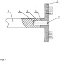
- FIG. 1 View of a device according to the invention for detachably connecting a rotor to a shaft for a pin mill.
- the figure 1 shows a shaft and a rotor of a pin mill with a detachable connection according to the invention, which connects a shaft 2 to a rotor 3 by means of a hydraulic clamping set 4 .
- the shaft 2 has a cylindrical recess 5 on its side facing the rotor 3 .
- the clamping set 4 is used. Approximately half of the clamping set 4 is accommodated in the recess 5 of the shaft 2 .
- the other side of the clamping set 4, which protrudes from the shaft 2, accommodates the rotor 3 at its hub 6.
- the rotor 3 is pushed onto the clamping set 4 so that the shaft 2 and the rotor 3 are flush.
- the clamping set 4 is clamped on the one side with the shaft 2 and on the other side with the rotor 4.
Landscapes
- Engineering & Computer Science (AREA)
- General Engineering & Computer Science (AREA)
- Physics & Mathematics (AREA)
- Fluid Mechanics (AREA)
- Mechanical Engineering (AREA)
- Food Science & Technology (AREA)
- Crushing And Pulverization Processes (AREA)
Description
- Die Erfindung betrifft eine Vorrichtung zum lösbaren Verbinden eines Rotors einer Maschine mit einer Welle.
- Rotoren von verfahrenstechnischen Maschinen, wie beispielsweise Zerkleinerungsmaschinen und Windsichter, werden über Passfederverbindungen, Spannsatzverbindungen oder Kegelsitze miteinander verbunden. Sie dienen als lösbare Verbindungen und der Drehmomentenübertragung von der Welle auf den Rotor.
- Bei schnelllaufenden Maschinen ist der Einsatz von Passfederverbindungen aufgrund ihres großen Passungsspiels nicht geeignet. Der Rotor wird zudem mit einer Schraubenverbindung verschraubt. Diese Schraubenverbindung muss mit dem entsprechenden Anzugsmoment angezogen werden, damit sie sich nicht löst. Um dieses Anzugsmoment aufbringen zu können, muss entsprechend gegengehalten werden. Dies erfordert immer aufwendige Gegenhalteeinrichtungen.
- Auch bei Kegelsitzverbindungen ist zum Anziehen der Schraubenverbindung eine Gegenhaltevorrichtung erforderlich. Bei Demontage muss nach dem Lösen der Schraubenverbindung zusätzlich der Kegelpressverband mit Hilfe einer Vorrichtung auseinander gepresst werden.
- Bei den bekannten Spannsätzen wird der Spannsatz auf die Welle montiert und die Nabe des Rotors sitzt auf dem Spannsatz und beide Bauteile werden miteinander verspannt. Dies lässt sich nur bei großen Nabendurchmessern mit entsprechender Nabendicke realisieren
- Eine derartige Vorrichtung ist aus
DE102010064215 bekannt. Aufgabe der Erfindung ist es eine Vorrichtung zur lösbaren Verbindung von Rotor und Welle zur Verfügung zu stellen, die ein schnelles und einfaches Montieren und Demontieren eines Rotors auf eine Welle ermöglicht. - Die Aufgabe wird durch eine Vorrichtung gemäß dem Anspruch 1 gelöst.
- Bei der erfindungsgemäßen Vorrichtung zur lösbaren Verbindung eines Rotors einer Maschine mit einer Welle mittels Spannsatz wird der Spannsatz zu einem Teil von der Welle und zum anderen Teil vom Rotor aufgenommen. Dafür ist die Welle auf ihrer dem Rotor zugewandten Seite mit einer zylindrischen Ausnehmung ausgebildet in die der Spannsatz eingesetzt wird. Auf die andere Seite des Spannsatzes wird der Rotor über seine Nabe aufgeschoben. Der Spannsatz wird über eine Spannmutter vom Arbeitsraum der verfahrenstechnischen Maschine von der wellenabgewandten Seite des Rotors verspannt. Der Spannsatz wird vollständig von Welle und Rotor umgeben. Idealerweise wird der Spannsatz je zur Hälfte von der Welle und dem Rotor aufgenommen.
- Der Spannsatz wird mit leichter Übergangpassung in die Welle geschrumpft, während der Rotor ein leichtes Spiel auf dem Spannsatz hat. Durch Anziehen des Spannsatzes wird der Spannsatz in der Welle und dem Werkzeug fixiert.
- Wird der Spannsatz gelöst, gibt er den Rotor frei, sodass dieser von der Welle abgenommen und ausgetauscht werden kann. Der Spannsatz selber verbleibt aufgrund seines leichten Übermaßes in der Welle. Ist ein Austausch des Spannsatzes notwendig wird er aus der Welle gelöst und ausgetauscht.
- Als Spannsatz kommen hydraulische Spannsätze zum Einsatz. Diese zeichnen sich durch eine geringe Einbaugröße mit hoher Kraftübertragung aus.
- Anwendung findet diese Art der lösbaren Verbindung von Rotor und Welle beispielsweise in verfahrenstechnischen Maschinen wie Zerkleinerungsmaschinen, Windsichter oder Mischer. Die Erfindung ist nicht auf diese Anwendungsbeispiele beschränkt.
- Eine solche lösbare Verbindung von Welle und Rotor kennzeichnet sich neben einem leichten und schnellen Ein- und Ausbaus des Rotors durch seine geringen Anzieh- und Lösedrehmomente an einer Schraube aus.
- Der Einsatz von Abziehvorrichtungen die bei Kegelsitz-Verbindungen notwendig sind, entfallen hier. Dies macht die Verbindung interessant für den Einsatz von verfahrenstechnischen Maschinen in Isolatorsystemen für pharmazeutische Anwendungen, da hier einfach zu bedienende Vorrichtungen Voraussetzung sind. Zum Ein- und Ausbau von Rotoren ist hier nur ein Werkzeug notwendig, welches mit geringem Kraftaufwand zu bedienen ist, sodass der Ausbau oder Austausch des Rotors auch unter erschwerten Bedingungen, wie sie in einem Isolator herrschen, einfach und leicht durchzuführen ist.
- Der Spannsatz sitzt je zur Hälfte in der Welle und im Rotor und ist von diesen vollständig umgeben, gleichzeitig sitzen Rotor und Welle auf Stoß sodass sich keine Störkanten im Produktstrom befinden, was zu geringen Produktrückständen im Arbeitsraum der Maschine führt und Voraussetzung für eine leichte und gute Reinigbarkeit der Maschine ist, speziell beim Einsatz in Isolatoren.
- Weitere Einzelheiten, Merkmale und Vorteile des Gegenstandes der Erfindung ergeben sich aus den Unteransprüchen sowie aus der nachfolgenden Beschreibung der zugehörigen Zeichnungen, in der -beispielhaft- ein bevorzugtes Ausführungsbeispiel der Erfindung dargestellt ist.
- In der Zeichnung zeigt:
Fig. 1 : Ansicht einer erfindungsgemäßen Vorrichtung zum lösbaren Verbinden eines Rotors mit einer Welle für eine Stiftmühle. - Die
Figur 1 zeigt eine Welle und einen Rotor einer Stiftmühle mit einer erfindungsgemäßen lösbaren Verbindung, welche eine Welle 2 mit einem Rotor 3 mittels hydraulischen Spannsatzes 4 verbindet. Die Welle 2 weißt an ihrem dem Rotor 3 zugewandten Seite eine zylindrische Ausnehmung 5 auf. In dieser Ausnehmung 5 wird der Spannsatz 4 eingesetzt. Der Spannsatz 4 wird ca. zur Hälfte in der Ausnehmung 5 der Welle 2 aufgenommen. Die andere Seite des Spannsatzes 4 die aus der Welle 2 ragt nimmt den Rotor 3 an seiner Nabe 6 auf. Der Rotor 3 wird auf den Spannsatz 4 geschoben sodass die Welle 2 und der Rotor 3 auf Stoß sitzen. Durch Drehen der Spannschaube 7 wird der Spannsatz 4 auf der einen Seite mit der Welle 2 verspannt und auf der anderen Seite mit dem Rotor 4. -
- 2
- Welle
- 3
- Rotor
- 4
- Spannsatz
- 5
- Ausnehmung
- 6
- Nabe
- 7
- Spannschraube
Claims (7)
- Vorrichtung umfassend einen Rotor (3) und eine Welle (2) einer Maschine, einen Spannsatz zum lösbaren Verbinden des Rotors (3) mit der Welle (2) wobei der Spannsatz (4) ein hydraulischer Spannsatz ist, der über sein erstes Ende eine achsgleiche Verbindung zum Rotor (3) herstellt und über sein zweites Ende eine achsgleiche Verbindung zur Welle (2) herstellt, wobei die Welle (2) auf ihrer dem Rotor (3) zugewandten Seite eine zylindrische Ausnehmung zu Aufnahme des Spannsatzes aufweist und der Rotor (3) auf seiner der Welle (2) zugewandten Seite über seine Nabe (6) auf den Spannsatz (4) gesteckt wird wobei der Spannsatz (4) wellenseitig eine Übergangspassung besitzt und durch schrumpfen befestigt ist.
- Vorrichtung nach Anspruch 1 wobei der Spannsatz (4) je zur Hälfte in der Welle (2) und im Rotor (3) sitzt.
- Vorrichtung nach Anspruch 1 und 2 wobei der
Spannsatz (4) über eine Schaube (7) auf der wellenabgewandten Seite des Rotors (3) verspannt wird. - Vorrichtung nach Anspruch 1 bis 3 wobei die Welle
(2) und der Rotor (3) in Achsrichtung auf Stoß sitzen und den Spannsatz (4) vollständig umgeben. - Vorrichtung nach Anspruch 1 wobei der Spannsatz
(4) rotorseitig Spiel besitzt. - Vorrichtung nach einem oder mehreren der vorangegangenen Ansprüche wobei
durch lösen des Spannsatzes (4) nur der Rotor (3) freigegeben wird und der Spannsatz (4) in der Welle (3) verbleibt. - Vorrichtung nach einem oder mehreren der vorangegangenen Ansprüche wobei
die Maschine eine verfahrenstechnische Maschine vorzugsweise eine Zerkleinerungsmaschine, ein Windsichter oder ein Mischer ist.
Applications Claiming Priority (1)
| Application Number | Priority Date | Filing Date | Title |
|---|---|---|---|
| DE102018001012.1A DE102018001012A1 (de) | 2018-02-08 | 2018-02-08 | Vorrichtung zum lösbaren Verbinden eines Rotors einer Maschine mit einer Welle |
Publications (2)
| Publication Number | Publication Date |
|---|---|
| EP3530971A1 EP3530971A1 (de) | 2019-08-28 |
| EP3530971B1 true EP3530971B1 (de) | 2022-07-06 |
Family
ID=65365766
Family Applications (1)
| Application Number | Title | Priority Date | Filing Date |
|---|---|---|---|
| EP19000071.1A Active EP3530971B1 (de) | 2018-02-08 | 2019-02-07 | Vorrichtung zum lösbaren verbinden eines rotors einer maschine mit einer welle |
Country Status (2)
| Country | Link |
|---|---|
| EP (1) | EP3530971B1 (de) |
| DE (1) | DE102018001012A1 (de) |
Family Cites Families (3)
| Publication number | Priority date | Publication date | Assignee | Title |
|---|---|---|---|---|
| DE4312207A1 (de) * | 1993-04-14 | 1994-10-20 | Kloeckner Humboldt Deutz Ag | Mahlwalze für Walzenmaschinen |
| DE102005061085A1 (de) * | 2005-12-21 | 2007-06-28 | Khd Humboldt Wedag Gmbh | Zweiwalzenmaschine insbesondere zur Gutbettzerkleinerung |
| DE102010064215B4 (de) * | 2010-12-27 | 2013-04-25 | Siemens Aktiengesellschaft | Rotor |
-
2018
- 2018-02-08 DE DE102018001012.1A patent/DE102018001012A1/de not_active Withdrawn
-
2019
- 2019-02-07 EP EP19000071.1A patent/EP3530971B1/de active Active
Also Published As
| Publication number | Publication date |
|---|---|
| EP3530971A1 (de) | 2019-08-28 |
| DE102018001012A1 (de) | 2019-08-08 |
Similar Documents
| Publication | Publication Date | Title |
|---|---|---|
| DE102008042437B4 (de) | Fluidbetriebener Drehmomentschlüssel und Verfahren zum Festziehen und Lösen von Befestigungsmitteln | |
| EP4208295B1 (de) | Fleischwolf | |
| EP2865897A2 (de) | Vorrichtung für einen Turbolader | |
| WO2022096556A1 (de) | Stützkreuz für einen fleischwolf | |
| DE202020105052U1 (de) | Fleischwolf | |
| EP0008631A1 (de) | Satzfräser | |
| DE202005002185U1 (de) | Vorrichtung zur variablen Demontage und Montage von Achsbauteilen | |
| EP2761194A1 (de) | Welle mit flanschverbindung | |
| DE202010003036U1 (de) | Feinstzerkleinerer | |
| EP3085447B1 (de) | Befestigungseinheit einer rührwerkskugelmühle, rührwerkskugelmühle und ein verfahren zum lösen einer befestigungseinheit | |
| EP3530971A1 (de) | Vorrichtung zum lösbaren verbinden eines rotors einer maschine mit einer welle | |
| DE102014220294A1 (de) | Spannsystem zum Vorspannen eines Zugangs einer Strömungskraftmaschine | |
| EP1749929B1 (de) | Vorrichtung zur Herstellung und/oder Behandlung einer Materialbahn, insbesondere Papier- oder Kartonbahn | |
| EP1533091A1 (de) | Spannvorrichtung für ein Werkzeugmaschinen-Bearbeitungselement | |
| EP1600055B1 (de) | Getriebe, und Futtermischer mit einem derartigen Getriebe | |
| DE102004001580B3 (de) | Vorrichtung zum Verbinden eines Schleifwerkzeugs mit einer Werkzeugmaschine | |
| DE102013110727A1 (de) | Verdichteranordnung für einen Turbolader | |
| DE102014219307B3 (de) | Vorrichtung zum Demontieren eines Lagerrings | |
| DE102011086851A1 (de) | Sicherheitselement für eine motorbetriebene Küchenmaschine sowie Küchenmaschine | |
| DE276394C (de) | ||
| WO2023208424A1 (de) | Messerwelle für eine längsschneideanlage zum schneiden von metallbändern und verfahren zum längsschneiden von metallbändern | |
| DE102008004884B4 (de) | Montagehilfe | |
| DE3537834C2 (de) | Elektromagnetische Kupplung | |
| DE112022007052T5 (de) | Rotor für einen Elektromotor | |
| DE102015209397A1 (de) | Mechanische Verbindung zwischen einem Antrieb und einer Welle einer Maschine mittels radialer Klemmung |
Legal Events
| Date | Code | Title | Description |
|---|---|---|---|
| PUAI | Public reference made under article 153(3) epc to a published international application that has entered the european phase |
Free format text: ORIGINAL CODE: 0009012 |
|
| STAA | Information on the status of an ep patent application or granted ep patent |
Free format text: STATUS: THE APPLICATION HAS BEEN PUBLISHED |
|
| AK | Designated contracting states |
Kind code of ref document: A1 Designated state(s): AL AT BE BG CH CY CZ DE DK EE ES FI FR GB GR HR HU IE IS IT LI LT LU LV MC MK MT NL NO PL PT RO RS SE SI SK SM TR |
|
| AX | Request for extension of the european patent |
Extension state: BA ME |
|
| STAA | Information on the status of an ep patent application or granted ep patent |
Free format text: STATUS: REQUEST FOR EXAMINATION WAS MADE |
|
| 17P | Request for examination filed |
Effective date: 20200221 |
|
| RBV | Designated contracting states (corrected) |
Designated state(s): AL AT BE BG CH CY CZ DE DK EE ES FI FR GB GR HR HU IE IS IT LI LT LU LV MC MK MT NL NO PL PT RO RS SE SI SK SM TR |
|
| GRAP | Despatch of communication of intention to grant a patent |
Free format text: ORIGINAL CODE: EPIDOSNIGR1 |
|
| STAA | Information on the status of an ep patent application or granted ep patent |
Free format text: STATUS: GRANT OF PATENT IS INTENDED |
|
| RIC1 | Information provided on ipc code assigned before grant |
Ipc: F16D 1/08 20060101ALI20220330BHEP Ipc: B02C 13/22 20060101ALI20220330BHEP Ipc: F16D 1/00 20060101AFI20220330BHEP |
|
| GRAS | Grant fee paid |
Free format text: ORIGINAL CODE: EPIDOSNIGR3 |
|
| INTG | Intention to grant announced |
Effective date: 20220503 |
|
| GRAA | (expected) grant |
Free format text: ORIGINAL CODE: 0009210 |
|
| STAA | Information on the status of an ep patent application or granted ep patent |
Free format text: STATUS: THE PATENT HAS BEEN GRANTED |
|
| AK | Designated contracting states |
Kind code of ref document: B1 Designated state(s): AL AT BE BG CH CY CZ DE DK EE ES FI FR GB GR HR HU IE IS IT LI LT LU LV MC MK MT NL NO PL PT RO RS SE SI SK SM TR |
|
| REG | Reference to a national code |
Ref country code: AT Ref legal event code: REF Ref document number: 1503073 Country of ref document: AT Kind code of ref document: T Effective date: 20220715 Ref country code: CH Ref legal event code: EP |
|
| REG | Reference to a national code |
Ref country code: DE Ref legal event code: R096 Ref document number: 502019004839 Country of ref document: DE |
|
| REG | Reference to a national code |
Ref country code: IE Ref legal event code: FG4D Free format text: LANGUAGE OF EP DOCUMENT: GERMAN |
|
| REG | Reference to a national code |
Ref country code: LT Ref legal event code: MG9D |
|
| REG | Reference to a national code |
Ref country code: NL Ref legal event code: MP Effective date: 20220706 |
|
| PG25 | Lapsed in a contracting state [announced via postgrant information from national office to epo] |
Ref country code: SE Free format text: LAPSE BECAUSE OF FAILURE TO SUBMIT A TRANSLATION OF THE DESCRIPTION OR TO PAY THE FEE WITHIN THE PRESCRIBED TIME-LIMIT Effective date: 20220706 Ref country code: RS Free format text: LAPSE BECAUSE OF FAILURE TO SUBMIT A TRANSLATION OF THE DESCRIPTION OR TO PAY THE FEE WITHIN THE PRESCRIBED TIME-LIMIT Effective date: 20220706 Ref country code: PT Free format text: LAPSE BECAUSE OF FAILURE TO SUBMIT A TRANSLATION OF THE DESCRIPTION OR TO PAY THE FEE WITHIN THE PRESCRIBED TIME-LIMIT Effective date: 20221107 Ref country code: NO Free format text: LAPSE BECAUSE OF FAILURE TO SUBMIT A TRANSLATION OF THE DESCRIPTION OR TO PAY THE FEE WITHIN THE PRESCRIBED TIME-LIMIT Effective date: 20221006 Ref country code: NL Free format text: LAPSE BECAUSE OF FAILURE TO SUBMIT A TRANSLATION OF THE DESCRIPTION OR TO PAY THE FEE WITHIN THE PRESCRIBED TIME-LIMIT Effective date: 20220706 Ref country code: LV Free format text: LAPSE BECAUSE OF FAILURE TO SUBMIT A TRANSLATION OF THE DESCRIPTION OR TO PAY THE FEE WITHIN THE PRESCRIBED TIME-LIMIT Effective date: 20220706 Ref country code: LT Free format text: LAPSE BECAUSE OF FAILURE TO SUBMIT A TRANSLATION OF THE DESCRIPTION OR TO PAY THE FEE WITHIN THE PRESCRIBED TIME-LIMIT Effective date: 20220706 Ref country code: FI Free format text: LAPSE BECAUSE OF FAILURE TO SUBMIT A TRANSLATION OF THE DESCRIPTION OR TO PAY THE FEE WITHIN THE PRESCRIBED TIME-LIMIT Effective date: 20220706 Ref country code: ES Free format text: LAPSE BECAUSE OF FAILURE TO SUBMIT A TRANSLATION OF THE DESCRIPTION OR TO PAY THE FEE WITHIN THE PRESCRIBED TIME-LIMIT Effective date: 20220706 |
|
| PG25 | Lapsed in a contracting state [announced via postgrant information from national office to epo] |
Ref country code: PL Free format text: LAPSE BECAUSE OF FAILURE TO SUBMIT A TRANSLATION OF THE DESCRIPTION OR TO PAY THE FEE WITHIN THE PRESCRIBED TIME-LIMIT Effective date: 20220706 Ref country code: IS Free format text: LAPSE BECAUSE OF FAILURE TO SUBMIT A TRANSLATION OF THE DESCRIPTION OR TO PAY THE FEE WITHIN THE PRESCRIBED TIME-LIMIT Effective date: 20221106 Ref country code: HR Free format text: LAPSE BECAUSE OF FAILURE TO SUBMIT A TRANSLATION OF THE DESCRIPTION OR TO PAY THE FEE WITHIN THE PRESCRIBED TIME-LIMIT Effective date: 20220706 Ref country code: GR Free format text: LAPSE BECAUSE OF FAILURE TO SUBMIT A TRANSLATION OF THE DESCRIPTION OR TO PAY THE FEE WITHIN THE PRESCRIBED TIME-LIMIT Effective date: 20221007 |
|
| REG | Reference to a national code |
Ref country code: DE Ref legal event code: R097 Ref document number: 502019004839 Country of ref document: DE |
|
| PG25 | Lapsed in a contracting state [announced via postgrant information from national office to epo] |
Ref country code: SM Free format text: LAPSE BECAUSE OF FAILURE TO SUBMIT A TRANSLATION OF THE DESCRIPTION OR TO PAY THE FEE WITHIN THE PRESCRIBED TIME-LIMIT Effective date: 20220706 Ref country code: RO Free format text: LAPSE BECAUSE OF FAILURE TO SUBMIT A TRANSLATION OF THE DESCRIPTION OR TO PAY THE FEE WITHIN THE PRESCRIBED TIME-LIMIT Effective date: 20220706 Ref country code: DK Free format text: LAPSE BECAUSE OF FAILURE TO SUBMIT A TRANSLATION OF THE DESCRIPTION OR TO PAY THE FEE WITHIN THE PRESCRIBED TIME-LIMIT Effective date: 20220706 Ref country code: CZ Free format text: LAPSE BECAUSE OF FAILURE TO SUBMIT A TRANSLATION OF THE DESCRIPTION OR TO PAY THE FEE WITHIN THE PRESCRIBED TIME-LIMIT Effective date: 20220706 |
|
| PLBE | No opposition filed within time limit |
Free format text: ORIGINAL CODE: 0009261 |
|
| STAA | Information on the status of an ep patent application or granted ep patent |
Free format text: STATUS: NO OPPOSITION FILED WITHIN TIME LIMIT |
|
| PG25 | Lapsed in a contracting state [announced via postgrant information from national office to epo] |
Ref country code: SK Free format text: LAPSE BECAUSE OF FAILURE TO SUBMIT A TRANSLATION OF THE DESCRIPTION OR TO PAY THE FEE WITHIN THE PRESCRIBED TIME-LIMIT Effective date: 20220706 Ref country code: EE Free format text: LAPSE BECAUSE OF FAILURE TO SUBMIT A TRANSLATION OF THE DESCRIPTION OR TO PAY THE FEE WITHIN THE PRESCRIBED TIME-LIMIT Effective date: 20220706 |
|
| 26N | No opposition filed |
Effective date: 20230411 |
|
| P01 | Opt-out of the competence of the unified patent court (upc) registered |
Effective date: 20230515 |
|
| PG25 | Lapsed in a contracting state [announced via postgrant information from national office to epo] |
Ref country code: AL Free format text: LAPSE BECAUSE OF FAILURE TO SUBMIT A TRANSLATION OF THE DESCRIPTION OR TO PAY THE FEE WITHIN THE PRESCRIBED TIME-LIMIT Effective date: 20220706 |
|
| PG25 | Lapsed in a contracting state [announced via postgrant information from national office to epo] |
Ref country code: SI Free format text: LAPSE BECAUSE OF FAILURE TO SUBMIT A TRANSLATION OF THE DESCRIPTION OR TO PAY THE FEE WITHIN THE PRESCRIBED TIME-LIMIT Effective date: 20220706 |
|
| PG25 | Lapsed in a contracting state [announced via postgrant information from national office to epo] |
Ref country code: MC Free format text: LAPSE BECAUSE OF FAILURE TO SUBMIT A TRANSLATION OF THE DESCRIPTION OR TO PAY THE FEE WITHIN THE PRESCRIBED TIME-LIMIT Effective date: 20220706 |
|
| REG | Reference to a national code |
Ref country code: BE Ref legal event code: MM Effective date: 20230228 |
|
| GBPC | Gb: european patent ceased through non-payment of renewal fee |
Effective date: 20230207 |
|
| PG25 | Lapsed in a contracting state [announced via postgrant information from national office to epo] |
Ref country code: LU Free format text: LAPSE BECAUSE OF NON-PAYMENT OF DUE FEES Effective date: 20230207 |
|
| REG | Reference to a national code |
Ref country code: IE Ref legal event code: MM4A |
|
| PG25 | Lapsed in a contracting state [announced via postgrant information from national office to epo] |
Ref country code: GB Free format text: LAPSE BECAUSE OF NON-PAYMENT OF DUE FEES Effective date: 20230207 |
|
| PG25 | Lapsed in a contracting state [announced via postgrant information from national office to epo] |
Ref country code: IT Free format text: LAPSE BECAUSE OF FAILURE TO SUBMIT A TRANSLATION OF THE DESCRIPTION OR TO PAY THE FEE WITHIN THE PRESCRIBED TIME-LIMIT Effective date: 20220706 Ref country code: IE Free format text: LAPSE BECAUSE OF NON-PAYMENT OF DUE FEES Effective date: 20230207 Ref country code: GB Free format text: LAPSE BECAUSE OF NON-PAYMENT OF DUE FEES Effective date: 20230207 Ref country code: FR Free format text: LAPSE BECAUSE OF NON-PAYMENT OF DUE FEES Effective date: 20230228 |
|
| PG25 | Lapsed in a contracting state [announced via postgrant information from national office to epo] |
Ref country code: BE Free format text: LAPSE BECAUSE OF NON-PAYMENT OF DUE FEES Effective date: 20230228 |
|
| PG25 | Lapsed in a contracting state [announced via postgrant information from national office to epo] |
Ref country code: BG Free format text: LAPSE BECAUSE OF FAILURE TO SUBMIT A TRANSLATION OF THE DESCRIPTION OR TO PAY THE FEE WITHIN THE PRESCRIBED TIME-LIMIT Effective date: 20220706 |
|
| PG25 | Lapsed in a contracting state [announced via postgrant information from national office to epo] |
Ref country code: BG Free format text: LAPSE BECAUSE OF FAILURE TO SUBMIT A TRANSLATION OF THE DESCRIPTION OR TO PAY THE FEE WITHIN THE PRESCRIBED TIME-LIMIT Effective date: 20220706 |
|
| REG | Reference to a national code |
Ref country code: AT Ref legal event code: MM01 Ref document number: 1503073 Country of ref document: AT Kind code of ref document: T Effective date: 20240207 |
|
| PG25 | Lapsed in a contracting state [announced via postgrant information from national office to epo] |
Ref country code: AT Free format text: LAPSE BECAUSE OF NON-PAYMENT OF DUE FEES Effective date: 20240207 |
|
| PG25 | Lapsed in a contracting state [announced via postgrant information from national office to epo] |
Ref country code: CY Free format text: LAPSE BECAUSE OF FAILURE TO SUBMIT A TRANSLATION OF THE DESCRIPTION OR TO PAY THE FEE WITHIN THE PRESCRIBED TIME-LIMIT; INVALID AB INITIO Effective date: 20190207 |
|
| PG25 | Lapsed in a contracting state [announced via postgrant information from national office to epo] |
Ref country code: HU Free format text: LAPSE BECAUSE OF FAILURE TO SUBMIT A TRANSLATION OF THE DESCRIPTION OR TO PAY THE FEE WITHIN THE PRESCRIBED TIME-LIMIT; INVALID AB INITIO Effective date: 20190207 |
|
| PG25 | Lapsed in a contracting state [announced via postgrant information from national office to epo] |
Ref country code: TR Free format text: LAPSE BECAUSE OF FAILURE TO SUBMIT A TRANSLATION OF THE DESCRIPTION OR TO PAY THE FEE WITHIN THE PRESCRIBED TIME-LIMIT Effective date: 20220706 |
|
| REG | Reference to a national code |
Ref country code: CH Ref legal event code: U11 Free format text: ST27 STATUS EVENT CODE: U-0-0-U10-U11 (AS PROVIDED BY THE NATIONAL OFFICE) Effective date: 20260301 |
|
| PGFP | Annual fee paid to national office [announced via postgrant information from national office to epo] |
Ref country code: DE Payment date: 20260218 Year of fee payment: 8 |
|
| PGFP | Annual fee paid to national office [announced via postgrant information from national office to epo] |
Ref country code: AT Payment date: 20260410 Year of fee payment: 5 |
|
| PGFP | Annual fee paid to national office [announced via postgrant information from national office to epo] |
Ref country code: CH Payment date: 20260301 Year of fee payment: 8 |