EP3530963B1 - Bed base connecting device - Google Patents
Bed base connecting device Download PDFInfo
- Publication number
- EP3530963B1 EP3530963B1 EP19158430.9A EP19158430A EP3530963B1 EP 3530963 B1 EP3530963 B1 EP 3530963B1 EP 19158430 A EP19158430 A EP 19158430A EP 3530963 B1 EP3530963 B1 EP 3530963B1
- Authority
- EP
- European Patent Office
- Prior art keywords
- longitudinal
- slatted frame
- parts
- locking element
- longitudinal spar
- Prior art date
- Legal status (The legal status is an assumption and is not a legal conclusion. Google has not performed a legal analysis and makes no representation as to the accuracy of the status listed.)
- Active
Links
- 229920003023 plastic Polymers 0.000 claims description 5
- 239000004033 plastic Substances 0.000 claims description 5
- 229910052751 metal Inorganic materials 0.000 claims description 4
- 239000002184 metal Substances 0.000 claims description 4
- 125000006850 spacer group Chemical group 0.000 claims description 4
- 229910000831 Steel Inorganic materials 0.000 claims description 3
- 239000000463 material Substances 0.000 claims description 3
- 239000010959 steel Substances 0.000 claims description 3
- 238000009434 installation Methods 0.000 claims 1
- 230000008878 coupling Effects 0.000 description 6
- 238000010168 coupling process Methods 0.000 description 6
- 238000005859 coupling reaction Methods 0.000 description 6
- 238000007142 ring opening reaction Methods 0.000 description 3
- XEEYBQQBJWHFJM-UHFFFAOYSA-N Iron Chemical compound [Fe] XEEYBQQBJWHFJM-UHFFFAOYSA-N 0.000 description 2
- 229910052782 aluminium Inorganic materials 0.000 description 2
- XAGFODPZIPBFFR-UHFFFAOYSA-N aluminium Chemical class [Al] XAGFODPZIPBFFR-UHFFFAOYSA-N 0.000 description 2
- 238000005299 abrasion Methods 0.000 description 1
- 238000005452 bending Methods 0.000 description 1
- 230000006835 compression Effects 0.000 description 1
- 238000007906 compression Methods 0.000 description 1
- 238000001125 extrusion Methods 0.000 description 1
- 229910052742 iron Inorganic materials 0.000 description 1
- 239000000203 mixture Substances 0.000 description 1
- 238000000465 moulding Methods 0.000 description 1
- 239000002023 wood Substances 0.000 description 1
Images

Classifications
-
- F—MECHANICAL ENGINEERING; LIGHTING; HEATING; WEAPONS; BLASTING
- F16—ENGINEERING ELEMENTS AND UNITS; GENERAL MEASURES FOR PRODUCING AND MAINTAINING EFFECTIVE FUNCTIONING OF MACHINES OR INSTALLATIONS; THERMAL INSULATION IN GENERAL
- F16B—DEVICES FOR FASTENING OR SECURING CONSTRUCTIONAL ELEMENTS OR MACHINE PARTS TOGETHER, e.g. NAILS, BOLTS, CIRCLIPS, CLAMPS, CLIPS OR WEDGES; JOINTS OR JOINTING
- F16B5/00—Joining sheets or plates, e.g. panels, to one another or to strips or bars parallel to them
- F16B5/12—Fastening strips or bars to sheets or plates, e.g. rubber strips, decorative strips for motor vehicles, by means of clips
- F16B5/121—Fastening strips or bars to sheets or plates, e.g. rubber strips, decorative strips for motor vehicles, by means of clips fastened over the edge(s) of the sheet(s) or plate(s)
-
- A—HUMAN NECESSITIES
- A47—FURNITURE; DOMESTIC ARTICLES OR APPLIANCES; COFFEE MILLS; SPICE MILLS; SUCTION CLEANERS IN GENERAL
- A47C—CHAIRS; SOFAS; BEDS
- A47C19/00—Bedsteads
- A47C19/04—Extensible bedsteads, e.g. with adjustment of length, width, height
-
- F—MECHANICAL ENGINEERING; LIGHTING; HEATING; WEAPONS; BLASTING
- F16—ENGINEERING ELEMENTS AND UNITS; GENERAL MEASURES FOR PRODUCING AND MAINTAINING EFFECTIVE FUNCTIONING OF MACHINES OR INSTALLATIONS; THERMAL INSULATION IN GENERAL
- F16B—DEVICES FOR FASTENING OR SECURING CONSTRUCTIONAL ELEMENTS OR MACHINE PARTS TOGETHER, e.g. NAILS, BOLTS, CIRCLIPS, CLAMPS, CLIPS OR WEDGES; JOINTS OR JOINTING
- F16B2/00—Friction-grip releasable fastenings
- F16B2/20—Clips, i.e. with gripping action effected solely by the inherent resistance to deformation of the material of the fastening
- F16B2/22—Clips, i.e. with gripping action effected solely by the inherent resistance to deformation of the material of the fastening of resilient material, e.g. rubbery material
-
- F—MECHANICAL ENGINEERING; LIGHTING; HEATING; WEAPONS; BLASTING
- F16—ENGINEERING ELEMENTS AND UNITS; GENERAL MEASURES FOR PRODUCING AND MAINTAINING EFFECTIVE FUNCTIONING OF MACHINES OR INSTALLATIONS; THERMAL INSULATION IN GENERAL
- F16B—DEVICES FOR FASTENING OR SECURING CONSTRUCTIONAL ELEMENTS OR MACHINE PARTS TOGETHER, e.g. NAILS, BOLTS, CIRCLIPS, CLAMPS, CLIPS OR WEDGES; JOINTS OR JOINTING
- F16B5/00—Joining sheets or plates, e.g. panels, to one another or to strips or bars parallel to them
- F16B5/12—Fastening strips or bars to sheets or plates, e.g. rubber strips, decorative strips for motor vehicles, by means of clips
- F16B5/123—Auxiliary fasteners specially designed for this purpose
Landscapes
- Engineering & Computer Science (AREA)
- General Engineering & Computer Science (AREA)
- Mechanical Engineering (AREA)
- Mutual Connection Of Rods And Tubes (AREA)
Description
Die Erfindung betrifft eine Lattenrost-Verbindungseinrichtung zum Verbinden von einem ersten und einem zweiten Längsholm-Teil eines Lattenrost-Längsholms an einer Verbindungsstelle. Ferner betrifft die Erfindung eine Verwendung einer Lattenrost-Verbindungseinrichtung an einem Lattenrost mit mindestens zwei Längsholm-Teilen.The invention relates to a slatted frame connecting device for connecting a first and a second longitudinal beam part of a slatted frame longitudinal beam at a connection point. The invention further relates to the use of a slatted frame connecting device on a slatted frame with at least two longitudinal beam parts.
Aus dem allgemeinen Stand der Technik ist es bekannt die Längsholme eines Lattenrostes, wie er insbesondere für Betten verwendet wird, teilbar zu gestalten. Dazu werden die Längsholme des Lattenrostes in mindestens zwei Längsholm-Teile aufgeteilt, die zum Zusammenfügen des fertigen Lattenrostes dann an einer Verbindungsstelle zu verbinden sind. Erst mit dem Zusammenfügen der Längsholm-Teile entsteht der dann sich in der Regel über die gesamte Länge des Lattenrostes erstreckende Lattenrost-Längsholm. Mit den einzelnen Längsholm-Teilen sind hingegen Teile bzw. Abschnitte des Lattenrostes geschaffen, die sich einfacher bewegen und auch einfacher transportieren lassen. Solche Lattenrost-Teile können insbesondere auf Norm-Paletten verladen und mittels diesen versendet und eingelagert werden.From the general state of the art it is known to make the longitudinal bars of a slatted frame, such as that used in particular for beds, divisible. For this purpose, the longitudinal bars of the slatted frame are divided into at least two longitudinal bar parts, which then have to be connected at a connection point to assemble the finished slatted frame. Only when the longitudinal beam parts are joined together does the longitudinal slatted frame beam, which usually extends over the entire length of the slatted frame, come into being. With the individual longitudinal beam parts, however, parts or sections of the slatted frame are created that are easier to move and also easier to transport. Such slatted frame parts can be loaded onto standard pallets and shipped and stored using them.
Aus
Aus
Aus
Da derartige Lattenroste aus Lattenrost-Teilen meist von den Endverbrauchern selbst zu fertigen Lattenrosten montiert werden, ist es besonders wichtig, dass diese Montage einfach und möglichst ohne Werkzeug vorgenommen werden kann. Zugleich muss der fertig montierte Lattenrost eine hohe Stabilität aufweisen.Since such slatted frames are usually assembled from slatted frame parts by the end users themselves to form finished slatted frames, it is particularly important that this assembly can be carried out easily and, if possible, without tools. At the same time, the fully assembled slatted frame must have a high level of stability.
Diese Aufgabe ist erfindungsgemäß mit einer Lattenrost-Verbindungseinrichtung zum Verbinden von einem ersten und einem zweiten Längsholm-Teil eines Lattenrost-Längsholms an einer Verbindungsstelle nach Anspruch 1 gelöst, bei der ein die Verbindungsstelle überbrückendes Längselement vorgesehen ist, an dem mindestens ein in das erste Längsholm-Teil einzugreifendes, erstes Querstück und mindestens ein in das zweite Längsholm-Teil einzugreifendes, zweites Querstück abstehen, und ein Sperrelement vorgesehen ist, mit dem ein Austreten der Querstücke aus dem zugehörigen Längsholm-Teil verhinderbar ist. Ferner ist die Erfindung auf eine Verwendung einer derartigen erfindungsgemäßen Lattenrost-Verbindungseinrichtung an einem Lattenrost mit mindestens zwei Längsholm-Teilen gerichtet.This object is achieved according to the invention with a slatted frame connecting device for connecting a first and a second longitudinal spar part of a slatted frame longitudinal spar at a connection point according to claim 1, in which a longitudinal element bridging the connection point is provided, on which at least one in the first longitudinal spar -The first cross piece to be engaged and at least one second cross piece to be engaged in the second longitudinal spar part protrude, and a locking element is provided with which the cross pieces can be prevented from emerging from the associated longitudinal spar part. Furthermore, the invention is directed to the use of such a slatted frame connecting device according to the invention on a slatted frame with at least two longitudinal beam parts.
Erfindungsgemäß ist eine einfache, sehr funktionale und zugleich sehr stabile Verbindung von Längsholm-Teilen eines Lattenrostes geschaffen. Die Montage bzw. das Zusammenfügen sowie auch die Demontage bzw. das Zerlegen des erfindungsgemäßen Lattenrostes ist dabei vollständig ohne Werkzeug möglich. Dies ist dadurch erreicht, dass die beiden Funktionen des stabilen Verbindens der Längsholm-Teile und des Sicherns dieser Verbindung getrennt in separaten Elementen ausgebildet bzw. realisiert sind. Unter Element wird hier ein Bauteil verstanden, insbesondere ein separates Bauteil, welches gezielt eine funktionale Wirkung entfaltet. Vorliegend sind dies als erstes Bauteil ein Längselement, das durch seine Längsstreckung eine brückenartige Verbindung zwischen den beiden beteiligten Längsholm-Teilen herstellt. Ferner ist als zweites Bauteil ein Sperrelement vorgesehen, welches eine Sicherung bzw. Sperre für das Längselement bildet. Das Sperrelement hält also das Längselement in seiner Wirklage und stellt damit sicher, dass dieses Längselement in dieser Lage ortsfest verbleibt und über die Nutzungsdauer des Lattenrostes hinweg als eigentlicher Verbinder der Längsholm-Teile wirkt.According to the invention, a simple, very functional and at the same time very stable connection of longitudinal spar parts of a slatted frame is created. The assembly or assembly as well as the disassembly or disassembly of the slatted frame according to the invention is possible completely without tools. This is achieved in that the two functions of stably connecting the longitudinal spar parts and securing this connection are designed or implemented separately in separate elements. An element here is understood to mean a component, in particular a separate component, which specifically develops a functional effect. In the present case, the first component is a longitudinal element, which, due to its longitudinal stretch, creates a bridge-like connection between the two the longitudinal spar parts involved. Furthermore, a locking element is provided as a second component, which forms a security or lock for the longitudinal element. The locking element therefore holds the longitudinal element in its active position and thus ensures that this longitudinal element remains stationary in this position and acts as the actual connector of the longitudinal spar parts over the service life of the slatted frame.
Die am Längselement ausgebildeten Querstücke stellen die Kopplung zu jeweils einem der Längsholm-Teile her. Diese Querstücke erstrecken sich quer zur Längserstreckung des Längselements und wirken dadurch als Bolzen bzw. Dorn, der in das zugehörige Längsholm-Teil hineinragt. Die Querstücke stellen so eine formschlüssige und damit besonders belastbare Kopplung zum Längsholm-Teil her. Zugleich ist eine derartige Kopplung besonders einfach mittels eines einfachen seitlichen Einschiebens der Querstücke in das zugehörige Längsholm-Teil herzustellen. Anschließend kann auf ebenfalls sehr einfache Weise die Gesamtverbindung durch ein Aufklipsen des Sperrelements wie erläutert dauerhaft gesichert werden.The cross pieces formed on the longitudinal element establish the coupling to one of the longitudinal spar parts. These cross pieces extend transversely to the longitudinal extent of the longitudinal element and thereby act as a bolt or mandrel that protrudes into the associated longitudinal spar part. The cross pieces create a positive and therefore particularly resilient connection to the longitudinal beam part. At the same time, such a coupling is particularly easy to produce by simply pushing the cross pieces laterally into the associated longitudinal spar part. The entire connection can then also be secured permanently in a very simple manner by clipping on the locking element as explained.
Bei einer vorteilhaften Weiterbildung der Erfindung sind an dem Längselement zwei erste Querstücke und zwei zweite Querstücke vorgesehen.In an advantageous development of the invention, two first cross pieces and two second cross pieces are provided on the longitudinal element.
Mittels mindestens zweier erster Querstücke und mindestens zweier zweiter Querstücke ist an dem jeweils zugehörigen Längsholm-Teil eine statisch klar bestimmte Ankopplung geschaffen, die als solche auch einzeln hergestellt und gelöst werden kann. Die Längsholm-Teile können also auch einzeln an die erfindungsgemäße Verbindungseinrichtung angebracht und von dieser gelöst werden. Ferner kann damit die Verbindungseinrichtung besonders vorteilhaft zunächst an nur einem Längsholm-Teil angeordnet werden und erst danach das zweite Längsholm-Teil zu dieser Gruppierung montiert werden. Erst danach braucht das erfindungsgemäße Sperrelement angebracht zu werden, um damit die Gesamtanordnung dauerhaft zu sichern. Eine Demontage der Gesamtanordnung ist in gleich einfacher Weise in umgekehrter Reihenfolge möglich.By means of at least two first cross pieces and at least two second cross pieces, a statically clearly defined coupling is created on the associated longitudinal spar part, which as such can also be produced and released individually. The longitudinal spar parts can also be individually attached to and detached from the connecting device according to the invention. Furthermore, the connecting device can thus be particularly advantageously initially arranged on only one longitudinal spar part and only then can the second longitudinal spar part be assembled into this grouping. Only then does the locking element according to the invention need to be attached in order to do so To permanently secure the entire arrangement. The entire arrangement can be dismantled in an equally simple manner in the reverse order.
Bei der erfindungsgemäßen Lattenrost-Verbindungseinrichtung ist ferner vorzugsweise an dem Längselement ein weiteres an der Verbindungsstelle einzugreifendes Querstück vorgesehen. Mit diesem an der Verbindungsstelle selbst eingreifenden Querstück kann ein definierter Abstand zwischen den Längsholm-Teilen eingestellt werden. Ferner kann mit nur einem Querstück eine Kopplung zu beiden beteiligten Längsholm-Teilen hergestellt werden. So kann insgesamt mit nur drei Querstücken eine Anbindung an zwei Längsholm-Teile geschaffen werden. Dies ist besonders vorteilhaft, weil zum Einbringen der Querstücke zugehörige Öffnungen an den Längsholm-Teilen, insbesondere Bohrungen, auszuformen sind. Dieses Ausformen erfordert gesonderte Arbeitsschritte, die es möglichst einzusparen gilt.In the slatted frame connecting device according to the invention, a further cross piece to be engaged at the connection point is also preferably provided on the longitudinal element. With this cross piece, which engages at the connection point itself, a defined distance between the longitudinal beam parts can be set. Furthermore, a coupling to both longitudinal spar parts involved can be created with just one cross piece. In total, a connection to two longitudinal spar parts can be created with just three cross pieces. This is particularly advantageous because corresponding openings, in particular bores, have to be formed on the longitudinal spar parts in order to introduce the cross pieces. This molding requires separate work steps that should be saved as much as possible.
Das Längselement ist vorzugsweise aus Metall, insbesondere Stahl, hergestellt. So kann mit geringem Material- und Platzbedarf eine hohe Stabilität der Kopplung der beiden beteiligten Längsholm-Teile geschaffen werden. Die Längsholm-Teile selbst sind dabei in der Regel aus Holz. Sie können aber auch aus Metall, insbesondere Aluminium, oder auch Kunststoff hergestellt sein. Stets ist eine einfache, kostengünstige und zugleich statisch hochwertige Kopplung mittels der genannten Querstücke möglich. Die Querstücke weisen dabei bevorzugt eine kreisrunde Querschnittsfläche auch, sind also vorzugsweise als Rundbolzen gestaltet. Alternativ weisen die Querstücke vorzugsweise eine quadratische oder rechteckige Querschnittsfläche auf.The longitudinal element is preferably made of metal, in particular steel. In this way, a high level of stability in the coupling of the two longitudinal spar parts involved can be achieved with little material and space requirements. The longitudinal spar parts themselves are usually made of wood. But they can also be made of metal, especially aluminum, or plastic. A simple, cost-effective and at the same time statically high-quality coupling is always possible using the cross pieces mentioned. The cross pieces preferably also have a circular cross-sectional area and are therefore preferably designed as round bolts. Alternatively, the cross pieces preferably have a square or rectangular cross-sectional area.
Das Sperrelement ist in bevorzugter Weise mit einem in zumindest eines der Längsholm-Teile einzugreifenden Bolzenstück gestaltet. Dieses Bolzenstück koppelt das Sperrelement an ein bzw. beide Längsholm-Teile und positioniert dieses damit. Zugleich wird das Sperrelement mit dem Bolzenstück ortsfest gehalten, so dass es dadurch das Längselement hinsichtlich dessen Lage sicher kann.The locking element is preferably designed with a bolt piece to engage in at least one of the longitudinal spar parts. This bolt piece couples the locking element to one or both longitudinal spar parts and thus positions it. At the same time, the locking element becomes stationary with the bolt piece held so that the longitudinal element can be secure in terms of its position.
Das Sperrelement ist erfindungsgemäß ferner mit einem das Längselement übergreifende Klammerstück mit einer Rastnase gestaltet. Das Klammerstück wirkt als ein Klipp, der beim Montieren des Sperrelements einfach manuell auf das Längselement aufgesetzt werden kann. Der Klipp übergreift damit das Längselement quer zur Richtung der Querstücke und verhindert dadurch, dass eines der Querstücke in dessen Axialrichtung aus dem zugehörigen Längsholm-Teil herauswandern könnte.According to the invention, the locking element is further designed with a clamp piece with a locking lug which extends over the longitudinal element. The clamp piece acts as a clip that can simply be placed manually on the longitudinal element when installing the locking element. The clip thus engages over the longitudinal element transversely to the direction of the cross pieces and thereby prevents one of the cross pieces from migrating out of the associated longitudinal spar part in its axial direction.
Das Sperrelement ist darüber hinaus vorteilhaft mit einem an der Verbindungsstelle zwischen den Längsholm-Teilen zu liegenden Abstandsstück gestaltet. Das Abstandsstück dient als Zwischenlage bzw. Zwischenschicht zwischen den Stirnseiten der beiden beteiligten Längsholm-Teilen, mittels der Geräusche und Abrieb zwischen diesen Stirnseiten der Längsholm-Teile vermieden werden können. Vorteilhaft ist das Abstandsstück zugleich von dem genannten Bolzenstück gebildet.The locking element is also advantageously designed with a spacer located at the connection point between the longitudinal spar parts. The spacer serves as an intermediate layer or intermediate layer between the end faces of the two longitudinal spar parts involved, by means of which noise and abrasion between these end faces of the longitudinal spar parts can be avoided. The spacer is advantageously also formed by the said bolt piece.
Das Sperrelement ist besonders kostengünstig und funktional vorteilhaft aus Kunststoff hergestellt. Dabei weist der verwendete Kunststoff bevorzugt eine derartige Materialzusammensetzung auf, dass eine gewisse Elastizität und Bruchfestigkeit gewährleistet ist.The locking element is made of plastic in a particularly cost-effective and functionally advantageous manner. The plastic used preferably has a material composition such that a certain elasticity and breaking strength is guaranteed.
Die Verbindungsstelle zwischen den beiden Längsholm-Teilen ist hinsichtlich ihrer Formgestaltung in verschiedener Art vorteilhaft auszubilden. Erfindungsgemäß bevorzugt ist eine Form, bei der die Stirnseiten der Längsholm-Teile in Gestalt einer Nut-Feder-Verbindung mit oder ohne Hinterschnitt ineinandergreifen. Ferner ist eine Form bevorzugt, bei der die Stirnseiten der Längsholm-Teile eine gerundete oder S-förmige Gestalt aufweisen. Mit derartigen Formen ist ein Vorpositionieren der Längsholm-Teile relativ zueinander vor deren Montage möglich.The connection point between the two longitudinal spar parts can be advantageously designed in various ways with regard to their shape. According to the invention, a shape is preferred in which the end faces of the longitudinal spar parts interlock with one another in the form of a tongue-and-groove connection with or without an undercut. Furthermore, a shape is preferred in which the end faces of the longitudinal spar parts have a rounded or S-shaped shape. With such shapes is a Pre-positioning of the longitudinal spar parts relative to each other before assembly is possible.
Nachfolgend werden Ausführungsbeispiele der erfindungsgemäßen Lösung anhand der beigefügten schematischen Zeichnungen näher erläutert. Es zeigt:
- Fig. 1
- eine perspektivische Ansicht einer ersten Ausführungsform einer erfindungsgemäßen Lattenrost-Verbindungeinrichtung in einem ersten Montagestadium,
- Fig. 2
- die Lattenrost-Verbindungseinrichtung gemäß
Fig. 1 in einem nachfolgenden, zweiten Montagestadium, - Fig. 3
- die Lattenrost-Verbindungseinrichtung gemäß
Fig. 1 in einem nachfolgenden, dritten Montagestadium und - Fig. 4
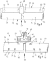
- eine perspektivische Ansicht einer zweiten Ausführungsform einer erfindungsgemäßen Lattenrost-Verbindungseinrichtung.
- Fig. 1
- a perspective view of a first embodiment of a slatted frame connecting device according to the invention in a first assembly stage,
- Fig. 2
- the slatted frame connecting device according to
Fig. 1 in a subsequent, second assembly stage, - Fig. 3
- the slatted frame connecting device according to
Fig. 1 in a subsequent, third assembly stage and - Fig. 4
- a perspective view of a second embodiment of a slatted frame connecting device according to the invention.
In den
Das erste Längsholm-Teil 14 endet an einer ersten Stirnseite 20 und das zweite Längsholm-Teil 16 endet an einer dieser Stirnseite 20 gegenüberliegenden Stirnseite 22. Auf diese Weise ist zwischen den Stirnseiten 20 und 22 eine Verbindungstelle 24 gebildet, an der die beiden Längsholm-Teile 14 und 16 einander mit etwas Abstand gegenüberliegen.The first
Die Lattenrost-Verbindungseinrichtung 10 ist mit einem Längselement 26 gestaltet, das aus Metall, vorliegend Stahl, hergestellt ist und ein Plattenstück 28 sowie vier Querstücke 30 umfasst. Das Plattenstück 28 ist als Streifen bzw. Flacheisen mit rechteckiger Querschnittfläche gestaltet und erstreckt sich in Längsrichtung 18 von dem ersten Längsholm-Teil 14 über die Verbindungsstelle 24 hinweg bis über das zweite Längsholm-Teil 16.The slatted
Dabei ragen die Querstücke 30 jeweils von dem Plattenstück 28 in eine Querrichtung 32 ab, die sich quer zur Längsrichtung 18 erstreckt. Zwei der vier Querstücke 30 befinden sich an jener Seite des Längselements 26, die das erste Längsholm-Teil 14 abdeckt. Die anderen zwei der vier Querstücke 30 befinden sich an der anderen Seite des Längselements 26, also dort, wo dieses den zweiten Längsholm-Teil 16 überdeckt. Die Querstücke 30 weisen dabei jeweils in Längsrichtung 18 einen gewissen Abstand auf und greifen im montierten Zustand (siehe
Die Queröffnungen 34 sind dazu mit entsprechenden Abständen in Seitenflächen 36 der Längsholm-Teile 14 und 16 als Sackbohrungen ausgebildet und hinsichtlich ihrer Querschnittsfläche genauso groß gestaltet, wie die Querstücke 30.For this purpose, the
Ferner ist bei der Lattenrost-Verbindungseinrichtung 10 ein Sperrelement 38 aus Kunststoff vorgesehen, das ein plattenförmiges Kopfstück 40 mit einem davon rechtwinklig abstehenden, kreiszylindrischen Bolzenstück 42 umfasst.Furthermore, a locking
Das Bolzenstück 42 ist in eine Bolzenöffnung 44 einzufügen, die im Bereich der Verbindungstelle 24 in Gestalt zweier Zylinderschalen an den beiden Stirnseiten 20 und 22 ausgebildet ist. Die Bolzenöffnung 44 ragt dabei bei der Ausführungsform gemäß
Das Sperrelement 38 weist ferner ein vom Kopfstück 40 seitlich abstehendes Klammerstück 48 auf, welches bei eingefügtem Bolzenstück 42 das Plattenstück 28 des Längselements 26 übergreift (siehe
Das Klammerstück 48 verhindert so im montierten Zustand, dass das Längselement 26 mit seinen Querstücken 30 aus den Queröffnungen 34 heraus wandern könnte.When assembled, the
Bei der Ausführungsform gemäß
Die Ringöffnungen 52 befinden sich an einer Oberseite 54 der Längsholm-Teile 14 und 16 und stellen dort eine auf Druck belastete Verbindung zwischen den Längsholm-Teilen 14 und 16 her. Zugleich hält das Bolzenstück 42 des Sperrelements 38 einen Abstand zwischen den Stirnseiten 20 und 22 sicher. So können insbesondere Reibgeräusche zwischen den Stirnseiten 20 und 22 vermieden werden.The
Eine Zug-Biege-Verbindung zwischen den Längsholm-Teilen 14 und 16 ist im Übrigen, wie auch bei der Ausführungsform gemäß
- 1010
- Lattenrost-VerbindungseinrichtungSlatted frame connection device
- 1212
- Lattenrost-LängsholmSlatted frame longitudinal beam
- 1414
- erstes Längsholm-Teilfirst longitudinal spar part
- 1616
- zweites Längsholm-Teilsecond longitudinal spar part
- 1818
- LängsrichtungLongitudinal direction
- 2020
- erste Stirnseitefirst face
- 2222
- zweite Stirnseitesecond end face
- 2424
- Verbindungsstelleconnection point
- 2626
- LängselementLongitudinal element
- 2828
- PlattenstückPlate piece
- 3030
- QuerstückCrosspiece
- 3232
- QuerrichtungTransverse direction
- 3434
- QueröffnungCross opening
- 3636
- Seitenflächeside surface
- 3838
- SperrelementLocking element
- 4040
- KopfstückHeadpiece
- 4242
- BolzenstückBolt piece
- 4444
- BolzenöffnungBolt opening
- 4646
- Unterseitebottom
- 4848
- KlammerstückClamp piece
- 5050
- RingstückRing piece
- 5252
- RingöffnungRing opening
- 5454
- OberseiteTop
Claims (8)
- Slatted frame connection device (10) for connecting a first and a second longitudinal beam part (14, 16) of a slatted frame longitudinal beam (12) at a connection point (24),wherein there is provided a longitudinal element (26) which is to bridge the connection point (24) and from which there protrude at least a first transverse member (30) which is to engage into the first longitudinal beam part (14) and at least a second transverse member (30) which is to engage into the second longitudinal beam part (16), and there is provided a locking element (38) with which the transverse members (30) can be prevented from coming out of the associated longitudinal beam part (14, 16),wherein the locking element (38) is designed with a bracket member (48) which has a latching projection and is to engage over the longitudinal element (26), wherein the bracket member acts as a clip which can be fitted to the longitudinal element (26) on installation of the locking element (38), and the clip is thus able to engage over the longitudinal element (26) transverse to the direction of the transverse members.
- Slatted frame connection device according to claim 1,
characterised in that two first transverse members (30) and two second transverse members (30) are provided on the longitudinal element (26). - Slatted frame connection device according to claim 1 or 2,
characterised in that a further transverse member which is to engage at the connection point (24) is provided on the longitudinal element (26). - Slatted frame connection device according to any one of claims 1 to 3, characterised in that the longitudinal element (26) is made of metal, in particular steel.
- Slatted frame connection device according to any one of claims 1 to 4, characterised in that the locking element (38) is designed with a pin member (42) which is to engage into at least one of the longitudinal beam parts (14, 16).
- Slatted frame connection device according to any one of claims 1 to 5, characterised in that the locking element (38) is equipped with a spacer which is to lie at the connection point (24) between the longitudinal beam parts (14, 16).
- Slatted frame connection device according to any one of claims 1 to 6, characterised in that the locking element (38) is made of plastics material.
- Use of a slatted frame connection device (10) according to any one of claims 1 to 7 on a slatted frame having at least two longitudinal beam parts (14, 16).
Applications Claiming Priority (1)
| Application Number | Priority Date | Filing Date | Title |
|---|---|---|---|
| DE102018103948.4A DE102018103948A1 (en) | 2018-02-21 | 2018-02-21 | SLATTED CONNECTION DEVICE |
Publications (3)
| Publication Number | Publication Date |
|---|---|
| EP3530963A1 EP3530963A1 (en) | 2019-08-28 |
| EP3530963B1 true EP3530963B1 (en) | 2023-10-04 |
| EP3530963C0 EP3530963C0 (en) | 2023-10-04 |
Family
ID=65520088
Family Applications (1)
| Application Number | Title | Priority Date | Filing Date |
|---|---|---|---|
| EP19158430.9A Active EP3530963B1 (en) | 2018-02-21 | 2019-02-21 | Bed base connecting device |
Country Status (2)
| Country | Link |
|---|---|
| EP (1) | EP3530963B1 (en) |
| DE (1) | DE102018103948A1 (en) |
Citations (1)
| Publication number | Priority date | Publication date | Assignee | Title |
|---|---|---|---|---|
| US6415465B1 (en) * | 2000-02-02 | 2002-07-09 | Lawrence M. Harrow | Bed frame with unique connector and method |
Family Cites Families (9)
| Publication number | Priority date | Publication date | Assignee | Title |
|---|---|---|---|---|
| DE7523178U (en) * | 1975-12-18 | Franke & Co Kg | Bed fitting | |
| DE815096C (en) * | 1950-03-31 | 1951-09-27 | Dalmine Spa | Butt connector for scaffolding tubes or rods |
| DE2103504C3 (en) * | 1971-01-15 | 1974-06-20 | Mannesmann Leichtbau Gmbh, 8000 Muenchen | Connector for profile tubes |
| US3871039A (en) * | 1974-05-09 | 1975-03-18 | Lear Siegler Inc | Bed frame |
| US4135266A (en) * | 1977-04-06 | 1979-01-23 | Lear Siegler, Inc. | Adjustable bed frame |
| DE29615173U1 (en) * | 1996-08-31 | 1996-11-07 | Doescher Handels Kg Geraetebau | Bed, in particular care bed for home and / or home care |
| DE202004014352U1 (en) * | 2004-09-13 | 2004-11-11 | C & M Beteiligung Gmbh | Bed frame has longitudinal bars made up of two sections which have recesses in ends nearest each other, into which connector fits so that bars form butt joint |
| CN2798729Y (en) * | 2005-06-21 | 2006-07-26 | 长城国际床业有限公司 | Improved bedstead fixing structure |
| US20110241502A1 (en) * | 2010-04-02 | 2011-10-06 | Pao-Yi Kao | Corner joint coupling structure of aluminum extrusion cabinet |
-
2018
- 2018-02-21 DE DE102018103948.4A patent/DE102018103948A1/en active Pending
-
2019
- 2019-02-21 EP EP19158430.9A patent/EP3530963B1/en active Active
Patent Citations (1)
| Publication number | Priority date | Publication date | Assignee | Title |
|---|---|---|---|---|
| US6415465B1 (en) * | 2000-02-02 | 2002-07-09 | Lawrence M. Harrow | Bed frame with unique connector and method |
Also Published As
| Publication number | Publication date |
|---|---|
| EP3530963A1 (en) | 2019-08-28 |
| DE102018103948A1 (en) | 2019-08-22 |
| EP3530963C0 (en) | 2023-10-04 |
Similar Documents
| Publication | Publication Date | Title |
|---|---|---|
| DE4210456C2 (en) | Cross connection for profile bars using tension members | |
| DE202013105584U1 (en) | Bearing for a substructure, for example a terrace | |
| EP3124734B1 (en) | Connection assembly for connecting a post on a frame profile of a window or a door made of plastic | |
| EP2636830B1 (en) | Door hinge fastening, assembly comprising the door hinge fastening and a door hinge and door assembly | |
| AT408773B (en) | SCREEN AND METHOD FOR PRODUCING SUCH A SCREEN | |
| EP2128366B1 (en) | Fitting for a sliding door | |
| EP2686501A1 (en) | Component assembly and suspension device for supporting rails and method for producing same | |
| EP3530963B1 (en) | Bed base connecting device | |
| EP1213490A1 (en) | Connection mean for profiled rods | |
| EP2754803B1 (en) | Espagnolette fitting for a window or door and driving rod for such an espagnolette fitting | |
| EP4047220B1 (en) | Assembly unit with at least one assembly rail and at least one retaining clip | |
| DE202013103254U1 (en) | Connection between profile elements of a frame construction | |
| DE2300532C2 (en) | Thermally insulating composite profile for window frames, door frames or the like | |
| EP0576429A1 (en) | Wooden folding ruler. | |
| EP2592283A1 (en) | Connector for furniture | |
| EP3296486B1 (en) | Building cladding with a fitting set for the joining of elongated cover elements | |
| EP3870864B1 (en) | Connection assembly | |
| EP2354432B1 (en) | Door leaf of a push door | |
| DE202017003846U1 (en) | Various materials, locking profile rail | |
| EP1101008A1 (en) | Drive rod fitting with corner deflection | |
| EP1950361A1 (en) | Scaffold board for scaffolding and method for its production | |
| DE102012104117B4 (en) | Connecting dowels and connection of two components | |
| DE2626407A1 (en) | Platform or shelving connector - has plug and socket with contours matching main stress line orthogonal trajectories | |
| DE202020106291U1 (en) | Arrangement of at least two angularly interconnected round tube profiles | |
| AT525491A1 (en) | Baffle wall for gymnasiums |
Legal Events
| Date | Code | Title | Description |
|---|---|---|---|
| PUAI | Public reference made under article 153(3) epc to a published international application that has entered the european phase |
Free format text: ORIGINAL CODE: 0009012 |
|
| STAA | Information on the status of an ep patent application or granted ep patent |
Free format text: STATUS: THE APPLICATION HAS BEEN PUBLISHED |
|
| AK | Designated contracting states |
Kind code of ref document: A1 Designated state(s): AL AT BE BG CH CY CZ DE DK EE ES FI FR GB GR HR HU IE IS IT LI LT LU LV MC MK MT NL NO PL PT RO RS SE SI SK SM TR |
|
| AX | Request for extension of the european patent |
Extension state: BA ME |
|
| STAA | Information on the status of an ep patent application or granted ep patent |
Free format text: STATUS: REQUEST FOR EXAMINATION WAS MADE |
|
| 17P | Request for examination filed |
Effective date: 20200227 |
|
| RBV | Designated contracting states (corrected) |
Designated state(s): AL AT BE BG CH CY CZ DE DK EE ES FI FR GB GR HR HU IE IS IT LI LT LU LV MC MK MT NL NO PL PT RO RS SE SI SK SM TR |
|
| STAA | Information on the status of an ep patent application or granted ep patent |
Free format text: STATUS: EXAMINATION IS IN PROGRESS |
|
| 17Q | First examination report despatched |
Effective date: 20200506 |
|
| STAA | Information on the status of an ep patent application or granted ep patent |
Free format text: STATUS: EXAMINATION IS IN PROGRESS |
|
| GRAP | Despatch of communication of intention to grant a patent |
Free format text: ORIGINAL CODE: EPIDOSNIGR1 |
|
| STAA | Information on the status of an ep patent application or granted ep patent |
Free format text: STATUS: GRANT OF PATENT IS INTENDED |
|
| INTG | Intention to grant announced |
Effective date: 20230531 |
|
| GRAS | Grant fee paid |
Free format text: ORIGINAL CODE: EPIDOSNIGR3 |
|
| GRAA | (expected) grant |
Free format text: ORIGINAL CODE: 0009210 |
|
| STAA | Information on the status of an ep patent application or granted ep patent |
Free format text: STATUS: THE PATENT HAS BEEN GRANTED |
|
| AK | Designated contracting states |
Kind code of ref document: B1 Designated state(s): AL AT BE BG CH CY CZ DE DK EE ES FI FR GB GR HR HU IE IS IT LI LT LU LV MC MK MT NL NO PL PT RO RS SE SI SK SM TR |
|
| REG | Reference to a national code |
Ref country code: GB Ref legal event code: FG4D Free format text: NOT ENGLISH |
|
| REG | Reference to a national code |
Ref country code: CH Ref legal event code: EP |
|
| REG | Reference to a national code |
Ref country code: DE Ref legal event code: R096 Ref document number: 502019009528 Country of ref document: DE |
|
| REG | Reference to a national code |
Ref country code: IE Ref legal event code: FG4D Free format text: LANGUAGE OF EP DOCUMENT: GERMAN |
|
| U01 | Request for unitary effect filed |
Effective date: 20231103 |
|
| U07 | Unitary effect registered |
Designated state(s): AT BE BG DE DK EE FI FR IT LT LU LV MT NL PT SE SI Effective date: 20231121 |
|
| U20 | Renewal fee paid [unitary effect] |
Year of fee payment: 6 Effective date: 20240215 |
|
| PG25 | Lapsed in a contracting state [announced via postgrant information from national office to epo] |
Ref country code: GR Free format text: LAPSE BECAUSE OF FAILURE TO SUBMIT A TRANSLATION OF THE DESCRIPTION OR TO PAY THE FEE WITHIN THE PRESCRIBED TIME-LIMIT Effective date: 20240105 |
|
| PG25 | Lapsed in a contracting state [announced via postgrant information from national office to epo] |
Ref country code: IS Free format text: LAPSE BECAUSE OF FAILURE TO SUBMIT A TRANSLATION OF THE DESCRIPTION OR TO PAY THE FEE WITHIN THE PRESCRIBED TIME-LIMIT Effective date: 20240204 |
|
| PG25 | Lapsed in a contracting state [announced via postgrant information from national office to epo] |
Ref country code: ES Free format text: LAPSE BECAUSE OF FAILURE TO SUBMIT A TRANSLATION OF THE DESCRIPTION OR TO PAY THE FEE WITHIN THE PRESCRIBED TIME-LIMIT Effective date: 20231004 |
|
| PG25 | Lapsed in a contracting state [announced via postgrant information from national office to epo] |
Ref country code: IS Free format text: LAPSE BECAUSE OF FAILURE TO SUBMIT A TRANSLATION OF THE DESCRIPTION OR TO PAY THE FEE WITHIN THE PRESCRIBED TIME-LIMIT Effective date: 20240204 Ref country code: GR Free format text: LAPSE BECAUSE OF FAILURE TO SUBMIT A TRANSLATION OF THE DESCRIPTION OR TO PAY THE FEE WITHIN THE PRESCRIBED TIME-LIMIT Effective date: 20240105 Ref country code: ES Free format text: LAPSE BECAUSE OF FAILURE TO SUBMIT A TRANSLATION OF THE DESCRIPTION OR TO PAY THE FEE WITHIN THE PRESCRIBED TIME-LIMIT Effective date: 20231004 |