EP2128366B1 - Fitting for a sliding door - Google Patents
Fitting for a sliding door Download PDFInfo
- Publication number
- EP2128366B1 EP2128366B1 EP09154198.7A EP09154198A EP2128366B1 EP 2128366 B1 EP2128366 B1 EP 2128366B1 EP 09154198 A EP09154198 A EP 09154198A EP 2128366 B1 EP2128366 B1 EP 2128366B1
- Authority
- EP
- European Patent Office
- Prior art keywords
- stop
- fastening projection
- rail
- fitting element
- element according
- Prior art date
- Legal status (The legal status is an assumption and is not a legal conclusion. Google has not performed a legal analysis and makes no representation as to the accuracy of the status listed.)
- Active
Links
Images


Classifications
-
- E—FIXED CONSTRUCTIONS
- E05—LOCKS; KEYS; WINDOW OR DOOR FITTINGS; SAFES
- E05F—DEVICES FOR MOVING WINGS INTO OPEN OR CLOSED POSITION; CHECKS FOR WINGS; WING FITTINGS NOT OTHERWISE PROVIDED FOR, CONCERNED WITH THE FUNCTIONING OF THE WING
- E05F5/00—Braking devices, e.g. checks; Stops; Buffers
- E05F5/003—Braking devices, e.g. checks; Stops; Buffers for sliding wings
-
- E—FIXED CONSTRUCTIONS
- E05—LOCKS; KEYS; WINDOW OR DOOR FITTINGS; SAFES
- E05D—HINGES OR SUSPENSION DEVICES FOR DOORS, WINDOWS OR WINGS
- E05D15/00—Suspension arrangements for wings
- E05D15/06—Suspension arrangements for wings for wings sliding horizontally more or less in their own plane
- E05D15/0621—Details, e.g. suspension or supporting guides
- E05D15/0626—Details, e.g. suspension or supporting guides for wings suspended at the top
- E05D15/0652—Tracks
-
- E—FIXED CONSTRUCTIONS
- E05—LOCKS; KEYS; WINDOW OR DOOR FITTINGS; SAFES
- E05Y—INDEXING SCHEME RELATING TO HINGES OR OTHER SUSPENSION DEVICES FOR DOORS, WINDOWS OR WINGS AND DEVICES FOR MOVING WINGS INTO OPEN OR CLOSED POSITION, CHECKS FOR WINGS AND WING FITTINGS NOT OTHERWISE PROVIDED FOR, CONCERNED WITH THE FUNCTIONING OF THE WING
- E05Y2201/00—Constructional elements; Accessories therefore
- E05Y2201/20—Brakes; Disengaging means, e.g. clutches; Holders, e.g. locks; Stops; Accessories therefore
- E05Y2201/218—Holders
-
- E—FIXED CONSTRUCTIONS
- E05—LOCKS; KEYS; WINDOW OR DOOR FITTINGS; SAFES
- E05Y—INDEXING SCHEME RELATING TO HINGES OR OTHER SUSPENSION DEVICES FOR DOORS, WINDOWS OR WINGS AND DEVICES FOR MOVING WINGS INTO OPEN OR CLOSED POSITION, CHECKS FOR WINGS AND WING FITTINGS NOT OTHERWISE PROVIDED FOR, CONCERNED WITH THE FUNCTIONING OF THE WING
- E05Y2201/00—Constructional elements; Accessories therefore
- E05Y2201/20—Brakes; Disengaging means, e.g. clutches; Holders, e.g. locks; Stops; Accessories therefore
- E05Y2201/224—Stops
-
- E—FIXED CONSTRUCTIONS
- E05—LOCKS; KEYS; WINDOW OR DOOR FITTINGS; SAFES
- E05Y—INDEXING SCHEME RELATING TO HINGES OR OTHER SUSPENSION DEVICES FOR DOORS, WINDOWS OR WINGS AND DEVICES FOR MOVING WINGS INTO OPEN OR CLOSED POSITION, CHECKS FOR WINGS AND WING FITTINGS NOT OTHERWISE PROVIDED FOR, CONCERNED WITH THE FUNCTIONING OF THE WING
- E05Y2201/00—Constructional elements; Accessories therefore
- E05Y2201/40—Motors; Magnets; Springs; Weights; Accessories therefore
- E05Y2201/47—Springs; Spring tensioners
- E05Y2201/48—Leaf springs
-
- E—FIXED CONSTRUCTIONS
- E05—LOCKS; KEYS; WINDOW OR DOOR FITTINGS; SAFES
- E05Y—INDEXING SCHEME RELATING TO HINGES OR OTHER SUSPENSION DEVICES FOR DOORS, WINDOWS OR WINGS AND DEVICES FOR MOVING WINGS INTO OPEN OR CLOSED POSITION, CHECKS FOR WINGS AND WING FITTINGS NOT OTHERWISE PROVIDED FOR, CONCERNED WITH THE FUNCTIONING OF THE WING
- E05Y2600/00—Mounting or coupling arrangements for elements provided for in this subclass
- E05Y2600/50—Mounting methods; Positioning
- E05Y2600/52—Toolless
- E05Y2600/528—Hooking, e.g. using bayonets; Locking
-
- E—FIXED CONSTRUCTIONS
- E05—LOCKS; KEYS; WINDOW OR DOOR FITTINGS; SAFES
- E05Y—INDEXING SCHEME RELATING TO HINGES OR OTHER SUSPENSION DEVICES FOR DOORS, WINDOWS OR WINGS AND DEVICES FOR MOVING WINGS INTO OPEN OR CLOSED POSITION, CHECKS FOR WINGS AND WING FITTINGS NOT OTHERWISE PROVIDED FOR, CONCERNED WITH THE FUNCTIONING OF THE WING
- E05Y2800/00—Details, accessories and auxiliary operations not otherwise provided for
- E05Y2800/20—Combinations of elements
- E05Y2800/205—Combinations of elements forming a unit
-
- E—FIXED CONSTRUCTIONS
- E05—LOCKS; KEYS; WINDOW OR DOOR FITTINGS; SAFES
- E05Y—INDEXING SCHEME RELATING TO HINGES OR OTHER SUSPENSION DEVICES FOR DOORS, WINDOWS OR WINGS AND DEVICES FOR MOVING WINGS INTO OPEN OR CLOSED POSITION, CHECKS FOR WINGS AND WING FITTINGS NOT OTHERWISE PROVIDED FOR, CONCERNED WITH THE FUNCTIONING OF THE WING
- E05Y2800/00—Details, accessories and auxiliary operations not otherwise provided for
- E05Y2800/20—Combinations of elements
- E05Y2800/21—Combinations of elements of identical elements, e.g. of identical compression springs
-
- E—FIXED CONSTRUCTIONS
- E05—LOCKS; KEYS; WINDOW OR DOOR FITTINGS; SAFES
- E05Y—INDEXING SCHEME RELATING TO HINGES OR OTHER SUSPENSION DEVICES FOR DOORS, WINDOWS OR WINGS AND DEVICES FOR MOVING WINGS INTO OPEN OR CLOSED POSITION, CHECKS FOR WINGS AND WING FITTINGS NOT OTHERWISE PROVIDED FOR, CONCERNED WITH THE FUNCTIONING OF THE WING
- E05Y2800/00—Details, accessories and auxiliary operations not otherwise provided for
- E05Y2800/73—Single use of elements
-
- E—FIXED CONSTRUCTIONS
- E05—LOCKS; KEYS; WINDOW OR DOOR FITTINGS; SAFES
- E05Y—INDEXING SCHEME RELATING TO HINGES OR OTHER SUSPENSION DEVICES FOR DOORS, WINDOWS OR WINGS AND DEVICES FOR MOVING WINGS INTO OPEN OR CLOSED POSITION, CHECKS FOR WINGS AND WING FITTINGS NOT OTHERWISE PROVIDED FOR, CONCERNED WITH THE FUNCTIONING OF THE WING
- E05Y2900/00—Application of doors, windows, wings or fittings thereof
- E05Y2900/20—Application of doors, windows, wings or fittings thereof for furnitures, e.g. cabinets
Definitions
- the present invention relates to a fitting element for a sliding door according to the preamble of claim 1.
- a sliding door braking device in which an end stop is provided, in which two resilient tongues can engage around a driver, which is coupled to a movable sliding door.
- the attachment of the stop takes place via screws which can be inserted into openings on the stop and provide for attachment to a holding part on the furniture.
- the attachment of such a stop by means of screws is relatively expensive, since an individual adjustment of the position of the stop must be made for each piece of furniture.
- a damping device for sliding door elements is known in which in particular a center stop is mounted on a rail.
- the center stop has a receptacle for engaging a roller, which is coupled to the sliding element.
- This center stop is also fixed by screws to a rail of the furniture.
- the FR 2 809 760 a multi-part stop with an elastic insert.
- At least one integrally formed fastening projection is provided on a rear wall of the stop, which can be fixed to an adjacent opening. This eliminates the need to set a stop mandatory with multiple screws on a rail or a wall element, since the determination can also be made via the at least one fastening projection.
- locking means are provided on a fastening projection.
- the stopper can be mounted in a predetermined position, in which the locking means are locked to the mounting projection.
- an opening for screwing is additionally formed on the stop.
- the stop is selectively fixed by the at least one fastening projection or rotated by 180 ° by a screw, so that the user can decide whether the simple mounting option on the mounting projection or the more expensive but possibly more stable attachment should be done via a screw.
- the stop can be mounted very flexibly.
- the opening passes through the fastening projection. As a result, a screw channel which has a sufficient length can be formed in the fastening projection.
- the fastening projection For a stable attachment of the fastening projection, it has a T-shaped cross-section in an embodiment according to the invention. Then, the fastening projection can be inserted at a corresponding slot on a rail, whereby a loss of security is given.
- a resilient latching hook may be formed on the fastening projection, which prevents accidental sliding of the stop, so that it is securely held on a rail or a wall element.
- at least one resilient leg is preferably provided for latching.
- two resilient legs are arranged, which engage around the driver U-shaped.
- the stopper two spaced bolt-shaped pin out, which can be fixed by clamping each having an opening of a rail or a wall element.
- the bolt-shaped pins are preferably tubular, so that a determination can be made either by clamping the pin or screwing the pin.
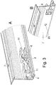
- a stopper 2 which has a receptacle 3, in which a driver on a moving furniture part, such as a sliding door, is inserted.
- the stopper 2 is designed as an end stop and fixed to a rail 7.
- a block 6 is provided as a stop on the receptacle 3, wherein adjacent to the block 6, two protruding spring legs 4 and 5 are provided which engage around a driver U-shaped and can engage this.
- the stopper 2 has a protruding fastening projection 8, which is fixed to a recess or opening 21 of the rail 7. In the FIGS. 2A to 2F the stopper 2 is shown in detail.
- the fastening projection 8 protrudes from a flat rear wall 9, which can be applied to a flat wall of the rail 7. As a result, the stopper 2 is held in position in a direction perpendicular to the rear wall 9 in position.
- an opening 11 is formed, which fully penetrates the stopper 2.
- a widening chamfer 17 is provided at the opening 11, which signals to the user that a screw can be fixed to the opening 11 on this side.
- a to the rear wall 9 opposite front wall 10 is flat and can also be applied to a flat side of a rail 7 if necessary.
- the protruding fastening projection 8 is T-shaped in cross-section and comprises a central portion which is connected to the stopper 2.
- strip-shaped projections 15 extend on opposite sides to the outside, wherein between the rear wall 9 and a strip-shaped projection 15, a gap 16 is formed.
- This gap 16 has a thickness which corresponds approximately to the wall thickness of the rail 7.
- a latching hook 12 is further formed on the side opposite to the resilient legs 4 and 5 side.
- the latching hook 12 is designed as a web and comprises a projecting in the direction of the front side projection 10 13. At this projection 13, a run-on slope 14 is formed on one side.
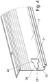
- FIGS. 3A and 3B the two possible mounting positions of the stop 2 are shown.
- the stop can be fixed either with the fastening projection 8 on the rail 7, as shown in the left stop 2. If no corresponding recess on the rail 7 is present, the stopper 2 can also be mounted with the front wall 10 directed to the rail 7 on the rail 7, in which case the fastening projection 8 protrudes outward as the right stop 2 in FIG. 3A shows. Then the user must make an attachment over the through opening 11, for example via screws. For this purpose, a corresponding circular opening 20 is to be made on the rail 7.
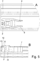
- the recess on the rail 7 for fixing the fastening projection 8 is in FIG. 4 shown.
- the recess 21 includes a first substantially rectangular portion 22 which is formed wider with respect to a direction of displacement of the stopper 2.
- This section 22 is adjoined by a lateral section 23, which is essentially U-shaped and in each case has a guide limb 24 on opposite sides.
- a smaller rectangular opening 25 is recessed in the rail at a distance.
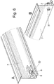
- the mounting of the stopper 2 by means of the fastening projection 8 will be described with reference to FIGS FIGS. 5A and 5B explained.
- the stopper 2 is placed on the rail 7 so that the fastening projection 8 passes through the portion 22 at the recess 21, wherein the fastening projection 8 can then be moved to the narrower portion 23.
- the stopper 2 must be positioned so that the wall of the rail 7 adjacent to the guide portions 24 engage in the gap 16 between the lateral projections 15 on the fastening projection 8 and the rear wall 9.
- the stopper 2 is now moved so far until the mounting hook is first bent up with the run-on slope 14 on the wall portion between the opening 25 and the recess 21 and then snaps into the opening 25, wherein the projection 13 is then inserted into the opening 25.
- the stopper 2 is secured against displacement in the opposite direction by the latching hook 12. Furthermore, the stopper 2 can not be in a direction perpendicular to the sliding direction be moved because there abut the lateral guide legs 24. The stopper 2 can also not be lifted from the rail 7, since the lateral projections 15 engage behind the rail 7. If the user finds no corresponding recess 21 on the rail 7 and the production of such a recess is not possible, the stopper 2 can be mounted rotated by 180 °, as shown in Figures 6A and 6B is shown. The user then only has to drill a circular opening in the rail 7 and then the stop 2 can be applied with the front wall 10 directed to the rail 7.
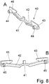
- FIG. 7 a second embodiment of a stop 40 is shown, which is designed as a center stop and has a receptacle 41 into which a driver can be inserted, which is held on a movable furniture part.
- the receptacle 41 is resilient, wherein on opposite sides in each case a leg 42 is provided. Each leg 42 is coupled to a mounting plate 43, the rear wall of a rail 7 can be applied.
- a bolt-shaped pin 44 protrudes, which is insertable into a circular opening 50 on the rail 7.
- the bolt-shaped pins 44 are designed so that they are dimensioned with oversize and are clamped to the circular opening 50 on the rail 7 can be fixed. It is also possible to deform the bolt-shaped pin 44 after insertion, for example, to emboss, so that then takes a stable determination of the center stop 40.
- Figures 8A and 8B the center stop 40 is shown in detail.
- the bolt-shaped pins 44 protrude from a rear wall 46, which is formed in particular on the two plates 43, but also on the resilient leg 42. This results in a flat contact surface for support on the rail. 7
- the stops 2 and 40 are made of an elastic material such as plastic in one piece. A preparation of rubber, rubber or, not according to the invention, a metal is possible.
Description
Die vorliegende Erfindung betrifft ein Beschlagselement für eine Schiebetür nach dem Oberbegriff des Anspruches 1.The present invention relates to a fitting element for a sliding door according to the preamble of claim 1.
Aus der
Aus der
Ferner offenbart die
Es ist daher Aufgabe der vorliegenden Erfindung ein Beschlagselement mit einem Anschlag für ein Möbel bereitzustellen, der sich auf einfache Weise flexibel montieren lässt.It is therefore an object of the present invention to provide a fitting element with a stop for a piece of furniture that can be mounted flexibly in a simple manner.
Diese Aufgabe wird mit einem Beschlagselement mit den Merkmalen des Anspruches 1 gelöst.This object is achieved with a fitting element having the features of claim 1.
Erfindungsgemäß ist mindestens ein integral ausgebildeter Befestigungsvorsprung an einer Rückwand des Anschlages vorgesehen, der an einer benachbarten Öffnung festlegbar ist. Dadurch entfällt die Notwendigkeit einen Anschlag zwingend mit mehreren Schrauben an einer Schiene oder einem Wandelement festzulegen, da die Festlegung auch über den mindestens einen Befestigungsvorsprung erfolgen kann.According to the invention, at least one integrally formed fastening projection is provided on a rear wall of the stop, which can be fixed to an adjacent opening. This eliminates the need to set a stop mandatory with multiple screws on a rail or a wall element, since the determination can also be made via the at least one fastening projection.
Dies vereinfacht die Montage erheblich, da der Anschlag auch ohne Werkzeug befestigt werden kann.
Gemäß einer bevorzugten Ausgestaltung der Erfindung sind an einem Befestigungsvorsprung Rastmittel vorgesehen. Dadurch kann der Anschlag in einer vorbestimmten Position montiert werden, in dem die Rastmittel an dem Befestigungsvorsprung eingerastet werden.
Vorzugsweise ist an dem Anschlag zusätzlich eine Öffnung zum Verschrauben ausgebildet. Es kann Anwendungsfälle geben, bei denen ein Verschrauben vorteilhaft ist, beispielsweise weil entsprechende Öffnungen an einer Schiene ausgespart sind oder hohe Belastungen wirken, bei denen ein Verschrauben für eine größere Lastabtragung sorgt. Der Anschlag ist dabei wahlweise durch den mindestens einen Befestigungsvorsprung oder um 180° gedreht durch eine Schraube fixierbar, so dass der Benutzer entscheiden kann, ob die einfache Montagemöglichkeit über den Befestigungsvorsprung oder die aufwendigere aber möglicherweise stabilere Befestigung über eine Schraube erfolgen soll. Der Anschlag kann so besonders flexibel montiert werden.
Vorzugsweise durchgreift die Öffnung den Befestigungsvorsprung. Dadurch kann in dem Befestigungsvorsprung ein Schraubkanal ausgebildet sein, der eine ausreichende Länge besitzt.This simplifies the assembly considerably, since the stop can be attached without tools.
According to a preferred embodiment of the invention locking means are provided on a fastening projection. Thereby, the stopper can be mounted in a predetermined position, in which the locking means are locked to the mounting projection.
Preferably, an opening for screwing is additionally formed on the stop. There may be applications in which a screw is advantageous, for example because corresponding openings are recessed on a rail or act high loads, where a screw provides for a larger load transfer. The stop is selectively fixed by the at least one fastening projection or rotated by 180 ° by a screw, so that the user can decide whether the simple mounting option on the mounting projection or the more expensive but possibly more stable attachment should be done via a screw. The stop can be mounted very flexibly.
Preferably, the opening passes through the fastening projection. As a result, a screw channel which has a sufficient length can be formed in the fastening projection.
Für eine stabile Befestigung des Befestigungsvorsprunges weist dieser in einer erfindungsgemäßen Ausführungsvariante einen T-förmigen Querschnitt aufweisen. Dann kann der Befestigungsvorsprung an einem entsprechenden Schlitz an einer Schiene eingeschoben werden, wodurch eine Verliersicherheit gegeben ist. Dabei kann an dem Befestigungsvorsprung ein federnder Rasthaken ausgebildet sein, der ein versehentliches Schieben des Anschlages verhindert, so dass dieser sicher an einer Schiene oder einem Wandelement gehalten ist.
Damit der Anschlag einen entsprechenden Mitnehmer halten kann, ist vorzugsweise mindestens ein federnder Schenkel zum Einrasten vorgesehen. Vorzugsweise sind zwei federnde Schenkel angeordnet, die den Mitnehmer U-förmig umgreifen.For a stable attachment of the fastening projection, it has a T-shaped cross-section in an embodiment according to the invention. Then, the fastening projection can be inserted at a corresponding slot on a rail, whereby a loss of security is given. In this case, a resilient latching hook may be formed on the fastening projection, which prevents accidental sliding of the stop, so that it is securely held on a rail or a wall element.
So that the stop can hold a corresponding driver, at least one resilient leg is preferably provided for latching. Preferably, two resilient legs are arranged, which engage around the driver U-shaped.
Gemäß einer weiteren Ausgestaltung der Erfindung stehen an der Rückwand des Anschlages zwei voneinander beabstandete bolzenförmige Zapfen hervor, die klemmend an jeweils einer Öffnung einer Schiene oder einem Wandelement festgelegt werden können. Die bolzenförmigen Zapfen sind vorzugsweise rohrförmig ausgebildet, so dass eine Festlegung wahlweise durch ein Klemmen der Zapfen oder ein Verschrauben der Zapfen erfolgen kann.According to a further embodiment of the invention are on the rear wall of the stopper two spaced bolt-shaped pin out, which can be fixed by clamping each having an opening of a rail or a wall element. The bolt-shaped pins are preferably tubular, so that a determination can be made either by clamping the pin or screwing the pin.
Die Erfindung wird nachfolgend anhand von zwei Ausführungsbeispielen mit Bezug auf die beigefügten Zeichnungen näher erläutert. Es zeigen:
- Figuren 1A und 1B
- zwei perspektivische Ansichten eines Anschlages nach einem ersten Ausführungsbeispiel in der montierten Position;
- Figuren 2A bis 2F
- mehrere Ansichten des Anschlages der
Figur 1 ; - Figuren 3A und 3B
- zwei perspektivische Ansichten des Anschlages der
Figur 1 in unterschiedlichen Montagepositionen; Figur 4- eine perspektivische Ansicht der Schiene zur Montage eines Anschlages der
Figur 1 ; - Figuren 5A und 5B
- zwei Ansichten des montierten Anschlages der
Figur 1 ; - Figuren 6A und 6B
- zwei Ansichten des Anschlages der
Figur 1 bei einer geschraubten Montage; Figur 7- eine perspektivische Ansicht eines Anschlages gemäß einem weiteren Ausführungsbeispiel, und
- Figuren 8A und 8B
- zwei Ansichten des Anschlages der
Figur 7
- Figures 1A and 1B
- two perspective views of a stop according to a first embodiment in the mounted position;
- FIGS. 2A to 2F
- several views of the stop of the
FIG. 1 ; - FIGS. 3A and 3B
- two perspective views of the stop the
FIG. 1 in different mounting positions; - FIG. 4
- a perspective view of the rail for mounting a stop of the
FIG. 1 ; - FIGS. 5A and 5B
- two views of the mounted stop of the
FIG. 1 ; - Figures 6A and 6B
- two views of the stop of the
FIG. 1 in a bolted assembly; - FIG. 7
- a perspective view of a stop according to a further embodiment, and
- Figures 8A and 8B
- two views of the stop of the
FIG. 7 ,
Bei einem Beschlagselement 1 für Schiebetüren ist ein Anschlag 2 vorgesehen, der eine Aufnahme 3 aufweist, in die ein Mitnehmer an einem bewegten Möbelteil, wie einer Schiebetür, einfügbar ist. Der Anschlag 2 ist als Endanschlag ausgebildet und an einer Schiene 7 festgelegt. Um den Mitnehmer anzuhalten, ist an der Aufnahme 3 ein Block 6 als Anschlag vorgesehen, wobei benachbart zu dem Block 6 zwei hervorstehende Federschenkel 4 und 5 vorgesehen sind, die einen Mitnehmer U-förmig umgreifen und diesen einrasten können.
Der Anschlag 2 weist einen hervorstehenden Befestigungsvorsprung 8 auf, der an einer Aussparung bzw. Öffnung 21 der Schiene 7 festgelegt ist.
In den
Der Befestigungsvorsprung 8 steht von einer ebenen Rückwand 9 hervor, die an einer ebenen Wand der Schiene 7 anlegbar ist. Dadurch ist der Anschlag 2 in eine Richtung senkrecht zur Rückwand 9 lagepositioniert gehalten. In dem Befestigungsvorsprung 8 ist eine Öffnung 11 ausgebildet, die den Anschlag 2 vollständig durchgreift. Auf der Seite des Befestigungsvorsprunges 8 ist an der Öffnung 11 eine sich aufweitende Fase 17 vorgesehen, die dem Benutzer signalisiert, dass auf dieser Seite eine Schraube an der Öffnung 11 festlegbar ist.
Eine zur Rückwand 9 gegenüberliegende Vorderwand 10 ist eben ausgebildet und kann bei Bedarf ebenfalls an eine ebene Seite einer Schiene 7 angelegt werden.
Der hervorstehende Befestigungsvorsprung 8 ist im Querschnitt T-förmig ausgebildet und umfasst einen Mittelabschnitt, der mit dem Anschlag 2 verbunden ist. Von diesem Mittelabschnitt erstrecken sich an gegenüberliegenden Seiten leistenförmige Vorsprünge 15 nach außen, wobei zwischen der Rückwand 9 und einem leistenförmigen Vorsprung 15 ein Spalt 16 ausgebildet ist. Dieser Spalt 16 weist eine Dicke auf, die etwa der Wandstärke der Schiene 7 entspricht.
An dem Befestigungsvorsprung 8 ist ferner auf der zu den federnden Schenkeln 4 und 5 gegenüberliegenden Seite ein Rasthaken 12 angeformt. Der Rasthaken 12 ist als Steg ausgebildet und umfasst einen in Richtung der Vorderseite 10 hervorstehenden Vorsprung 13. An diesem Vorsprung 13 ist an einer Seite eine Anlaufschräge 14 ausgebildet.In a fitting element 1 for sliding doors a
The
In the
The
A to the
The protruding
On the
In den
Die Aussparung an der Schiene 7 zur Festlegung des Befestigungsvorsprunges 8 ist in
Die Montage des Anschlages 2 mittels des Befestigungsvorsprunges 8 wird mit Bezug auf die
Falls der Benutzer keine entsprechende Aussparung 21 an der Schiene 7 vorfindet und die Herstellung einer solchen Aussparung auch nicht möglich ist, kann der Anschlag 2 um 180° gedreht montiert werden, wie dies in
In
If the user finds no corresponding
In
Die Anschläge 2 und 40 sind aus einem elastischen Material, wie Kunststoff einstückig hergestellt. Auch eine Herstellung aus Kautschuk, Gummi oder, nicht erfindungsgemäß, einem Metall ist möglich.The
Claims (10)
- Fitting element (1) for a sliding door, comprising a rail (7) and a stop (2, 40) with a receptacle (3, 41) into which a catch can be inserted, which is coupled to a movable furniture part, and a rear wall (9, 46) which is applied to the rail (7), wherein the stop (2, 40) is integrally made of an elastic material, characterized in that at least one integrally formed fastening projection (8, 44) protrudes from the rear wall (9, 46), which is fixed in an adjacent opening (21, 50) of the rail (7), wherein the fastening projection (8) has a T-shaped cross-section and is inserted at a corresponding slot of the opening (21) on the rail (7), or two mutually spaced bolt-shaped pins (44) protrude as fastening projections on the rear wall (46), which are fixed in a clamped manner to the opening (50) of the rail (7).
- Fitting element according to claim 1, wherein the at least one fastening projection (8) has the T-shaped cross-section, characterized in that latching means (12) are provided on a fastening projection (8).
- Fitting element according to claim 1 or 2, characterized in that an opening (11, 45) is additionally designed for bolting on the stop (2, 40).
- Fitting element according to one of the claims 1 to 3, wherein the at least one fastening projection (8) has the T-shaped cross-section, characterized in that the stop (2) is selectively fixable by the at least one fastening projection (8,) or rotated by 180°, by a screw (30).
- Fitting element according to claim 3, characterized in that the opening (11, 45) of the stop (2, 40) passes through a fastening projection (8).
- Fitting element according to one of the claims 1 to 5, wherein the at least one fastening projection (8) has the T-shaped cross-section, characterized in that a resilient latching hook (12) is formed on the fastening projection (8).
- Fitting element according to one of the claims 1 to 6, characterized in that at least one resilient leg (4, 5, 42) for locking the catch is formed on the receptacle (3, 41).
- Fitting element according to one of the claims 1 to 7, wherein the at least one fastening projection (8) has the T-shaped cross section, characterized in that two resilient legs (4, 5) engage around the catch in a U-shaped manner.
- Fitting element according to claim 1, wherein the bolt-shaped pins are provided as fastening projections (44), characterized in that the bolt-shaped pins (44) are formed in a tubular manner.
- Fitting element according to one of the claims 1 to 9, characterized in that the stop (2, 40) is made of plastic.
Priority Applications (1)
| Application Number | Priority Date | Filing Date | Title |
|---|---|---|---|
| PL09154198T PL2128366T3 (en) | 2008-04-17 | 2009-03-03 | Fitting for a sliding door |
Applications Claiming Priority (1)
| Application Number | Priority Date | Filing Date | Title |
|---|---|---|---|
| DE202008005264U DE202008005264U1 (en) | 2008-04-17 | 2008-04-17 | Stop for a furniture |
Publications (3)
| Publication Number | Publication Date |
|---|---|
| EP2128366A2 EP2128366A2 (en) | 2009-12-02 |
| EP2128366A3 EP2128366A3 (en) | 2014-01-01 |
| EP2128366B1 true EP2128366B1 (en) | 2018-06-20 |
Family
ID=40716963
Family Applications (1)
| Application Number | Title | Priority Date | Filing Date |
|---|---|---|---|
| EP09154198.7A Active EP2128366B1 (en) | 2008-04-17 | 2009-03-03 | Fitting for a sliding door |
Country Status (4)
| Country | Link |
|---|---|
| EP (1) | EP2128366B1 (en) |
| DE (1) | DE202008005264U1 (en) |
| PL (1) | PL2128366T3 (en) |
| TR (1) | TR201811267T4 (en) |
Families Citing this family (5)
| Publication number | Priority date | Publication date | Assignee | Title |
|---|---|---|---|---|
| DE102010030258B3 (en) * | 2010-06-18 | 2011-11-17 | Geze Gmbh | Sliding door system and method for mounting a sliding door system |
| DE102016118880A1 (en) | 2016-10-05 | 2018-04-19 | Hettich-Heinze Gmbh & Co. Kg | Fitting for a sliding door or a folding sliding door |
| PL72212Y1 (en) * | 2017-11-03 | 2021-11-02 | Valcomp Spółka Z Ograniczoną Odpowiedzialnością | Sliding shock-absorbing stopper |
| US20220316251A1 (en) * | 2020-04-29 | 2022-10-06 | Çemobsan Metal Ve Plastik Sanayi Ticaret Limited Sirketi | A sliding system |
| DE202020104455U1 (en) * | 2020-07-31 | 2021-11-05 | Hettich-Heinze Gmbh & Co. Kg | Guide device and furniture |
Citations (2)
| Publication number | Priority date | Publication date | Assignee | Title |
|---|---|---|---|---|
| JPS4899639U (en) * | 1972-02-22 | 1973-11-24 | ||
| EP1528205A1 (en) * | 2003-10-27 | 2005-05-04 | Peugeot Citroen Automobiles S.A. | Centering device for a sliding door of a motor vehicle |
Family Cites Families (6)
| Publication number | Priority date | Publication date | Assignee | Title |
|---|---|---|---|---|
| DE7440500U (en) * | 1975-04-10 | Hettich P & Co | Furniture with at least one hinged door and one stop damper assigned to the door | |
| DE7003690U (en) * | 1970-02-04 | 1970-06-11 | Bocklenberg & Motte Bomoro | BUFFER DEVICE, IN PARTICULAR ON LOCKING DEVICES FOR MOTOR VEHICLE DOORS. |
| DE7610590U1 (en) | 1976-04-06 | 1976-11-18 | Fa. Richard Heinze, 4900 Herford | BRAKE DEVICE FOR SLIDING DOORS, IN PARTICULAR FOR SLIDING DOORS ON FURNITURE |
| DE19914860B4 (en) * | 1998-09-16 | 2006-01-19 | Robert Bosch Gmbh | Guiding and limiting movement device for sliding door component has receiving and stop component working in conjunction with centering component, with receiving and stop component |
| FR2809760A1 (en) | 2000-06-05 | 2001-12-07 | Jacques Pezin | Friction damper used to arrest sliding door, comprises casing containing plate deflecting progressively against resilient elastomer as door finger advances |
| DE20018838U1 (en) | 2000-11-04 | 2001-02-08 | Hettich Heinze Gmbh & Co Kg | Adjustable stop and damping device for sliding and / or folding sliding door elements |
-
2008
- 2008-04-17 DE DE202008005264U patent/DE202008005264U1/en not_active Expired - Lifetime
-
2009
- 2009-03-03 TR TR2018/11267T patent/TR201811267T4/en unknown
- 2009-03-03 PL PL09154198T patent/PL2128366T3/en unknown
- 2009-03-03 EP EP09154198.7A patent/EP2128366B1/en active Active
Patent Citations (2)
| Publication number | Priority date | Publication date | Assignee | Title |
|---|---|---|---|---|
| JPS4899639U (en) * | 1972-02-22 | 1973-11-24 | ||
| EP1528205A1 (en) * | 2003-10-27 | 2005-05-04 | Peugeot Citroen Automobiles S.A. | Centering device for a sliding door of a motor vehicle |
Also Published As
| Publication number | Publication date |
|---|---|
| EP2128366A3 (en) | 2014-01-01 |
| EP2128366A2 (en) | 2009-12-02 |
| TR201811267T4 (en) | 2018-08-27 |
| DE202008005264U1 (en) | 2009-09-03 |
| PL2128366T3 (en) | 2018-11-30 |
Similar Documents
| Publication | Publication Date | Title |
|---|---|---|
| EP1916361A1 (en) | Handle for mounting in an opening | |
| EP2128366B1 (en) | Fitting for a sliding door | |
| DE4032865C2 (en) | Screw connection | |
| DE19730600A1 (en) | Cuff rail fitting | |
| EP2754803B1 (en) | Espagnolette fitting for a window or door and driving rod for such an espagnolette fitting | |
| EP0937847A1 (en) | Faceplate fixable to a fitting groove, particularly for covering an actuating rod of door, window or the like in at least one part | |
| EP1193822B1 (en) | Bus bar support | |
| EP1229282B1 (en) | Adaptor for the mounting of clamping collar | |
| AT408561B (en) | Protective fence | |
| EP2067906B1 (en) | Connection system for trough shaped profile bars and connection arrangement | |
| EP3535824B1 (en) | Busbar holder and corresponding assembly | |
| DE3913319C2 (en) | ||
| DE202016103609U1 (en) | Adapter for mounting on a fixed point of a vehicle | |
| DE102010060672B4 (en) | Window or door frame | |
| DE19712117A1 (en) | Device for attaching sun or privacy protection devices | |
| DE102004043964A1 (en) | connecting device | |
| EP1028205B1 (en) | Support for the lateral guide rails of a conservatory awning | |
| EP2090789B1 (en) | Connector for trough shaped profile bars and connection arrangement | |
| EP1335138B1 (en) | Profiled bar connection | |
| DE19828233A1 (en) | Wall bracket for a heater body | |
| AT524703B1 (en) | Floor guide device for a sliding door assembly | |
| BE1028531B1 (en) | Fastening device, method, arrangement and control cabinet | |
| EP0945574B1 (en) | Hinge for doors, windows or the like | |
| DE102006032943A1 (en) | Vehicle handle, has metal fastener to fasten bearing block at vehicle body, and locking unit found between side panels of fastener to block movement of elastic rest tongue of rest section, where section forms rest connection with body | |
| WO2020233843A1 (en) | Rear wall connector for drawers |
Legal Events
| Date | Code | Title | Description |
|---|---|---|---|
| PUAI | Public reference made under article 153(3) epc to a published international application that has entered the european phase |
Free format text: ORIGINAL CODE: 0009012 |
|
| AK | Designated contracting states |
Kind code of ref document: A2 Designated state(s): AT BE BG CH CY CZ DE DK EE ES FI FR GB GR HR HU IE IS IT LI LT LU LV MC MK MT NL NO PL PT RO SE SI SK TR |
|
| AX | Request for extension of the european patent |
Extension state: AL BA RS |
|
| PUAL | Search report despatched |
Free format text: ORIGINAL CODE: 0009013 |
|
| AK | Designated contracting states |
Kind code of ref document: A3 Designated state(s): AT BE BG CH CY CZ DE DK EE ES FI FR GB GR HR HU IE IS IT LI LT LU LV MC MK MT NL NO PL PT RO SE SI SK TR |
|
| AX | Request for extension of the european patent |
Extension state: AL BA RS |
|
| RIC1 | Information provided on ipc code assigned before grant |
Ipc: E05F 5/00 20060101ALI20131128BHEP Ipc: E05D 13/00 20060101AFI20131128BHEP |
|
| 17P | Request for examination filed |
Effective date: 20140320 |
|
| RBV | Designated contracting states (corrected) |
Designated state(s): AT BE BG CH CY CZ DE DK EE ES FI FR GB GR HR HU IE IS IT LI LT LU LV MC MK MT NL NO PL PT RO SE SI SK TR |
|
| AKX | Designation fees paid |
Designated state(s): AT BE BG CH CY CZ DE DK EE ES FI FR GB GR HR HU IE IS IT LI LT LU LV MC MK MT NL NO PL PT RO SE SI SK TR |
|
| RAP1 | Party data changed (applicant data changed or rights of an application transferred) |
Owner name: HETTICH-HEINZE GMBH & CO. KG |
|
| 17Q | First examination report despatched |
Effective date: 20160504 |
|
| GRAP | Despatch of communication of intention to grant a patent |
Free format text: ORIGINAL CODE: EPIDOSNIGR1 |
|
| STAA | Information on the status of an ep patent application or granted ep patent |
Free format text: STATUS: GRANT OF PATENT IS INTENDED |
|
| INTG | Intention to grant announced |
Effective date: 20180306 |
|
| GRAS | Grant fee paid |
Free format text: ORIGINAL CODE: EPIDOSNIGR3 |
|
| GRAA | (expected) grant |
Free format text: ORIGINAL CODE: 0009210 |
|
| STAA | Information on the status of an ep patent application or granted ep patent |
Free format text: STATUS: THE PATENT HAS BEEN GRANTED |
|
| AK | Designated contracting states |
Kind code of ref document: B1 Designated state(s): AT BE BG CH CY CZ DE DK EE ES FI FR GB GR HR HU IE IS IT LI LT LU LV MC MK MT NL NO PL PT RO SE SI SK TR |
|
| REG | Reference to a national code |
Ref country code: GB Ref legal event code: FG4D Free format text: NOT ENGLISH |
|
| REG | Reference to a national code |
Ref country code: IE Ref legal event code: FG4D Free format text: LANGUAGE OF EP DOCUMENT: GERMAN |
|
| REG | Reference to a national code |
Ref country code: DE Ref legal event code: R096 Ref document number: 502009015034 Country of ref document: DE |
|
| REG | Reference to a national code |
Ref country code: AT Ref legal event code: REF Ref document number: 1010717 Country of ref document: AT Kind code of ref document: T Effective date: 20180715 |
|
| REG | Reference to a national code |
Ref country code: DE Ref legal event code: R084 Ref document number: 502009015034 Country of ref document: DE |
|
| REG | Reference to a national code |
Ref country code: NL Ref legal event code: MP Effective date: 20180620 |
|
| PG25 | Lapsed in a contracting state [announced via postgrant information from national office to epo] |
Ref country code: LT Free format text: LAPSE BECAUSE OF FAILURE TO SUBMIT A TRANSLATION OF THE DESCRIPTION OR TO PAY THE FEE WITHIN THE PRESCRIBED TIME-LIMIT Effective date: 20180620 Ref country code: NO Free format text: LAPSE BECAUSE OF FAILURE TO SUBMIT A TRANSLATION OF THE DESCRIPTION OR TO PAY THE FEE WITHIN THE PRESCRIBED TIME-LIMIT Effective date: 20180920 Ref country code: BG Free format text: LAPSE BECAUSE OF FAILURE TO SUBMIT A TRANSLATION OF THE DESCRIPTION OR TO PAY THE FEE WITHIN THE PRESCRIBED TIME-LIMIT Effective date: 20180920 Ref country code: SE Free format text: LAPSE BECAUSE OF FAILURE TO SUBMIT A TRANSLATION OF THE DESCRIPTION OR TO PAY THE FEE WITHIN THE PRESCRIBED TIME-LIMIT Effective date: 20180620 Ref country code: FI Free format text: LAPSE BECAUSE OF FAILURE TO SUBMIT A TRANSLATION OF THE DESCRIPTION OR TO PAY THE FEE WITHIN THE PRESCRIBED TIME-LIMIT Effective date: 20180620 |
|
| REG | Reference to a national code |
Ref country code: LT Ref legal event code: MG4D |
|
| PG25 | Lapsed in a contracting state [announced via postgrant information from national office to epo] |
Ref country code: HR Free format text: LAPSE BECAUSE OF FAILURE TO SUBMIT A TRANSLATION OF THE DESCRIPTION OR TO PAY THE FEE WITHIN THE PRESCRIBED TIME-LIMIT Effective date: 20180620 Ref country code: GR Free format text: LAPSE BECAUSE OF FAILURE TO SUBMIT A TRANSLATION OF THE DESCRIPTION OR TO PAY THE FEE WITHIN THE PRESCRIBED TIME-LIMIT Effective date: 20180921 Ref country code: LV Free format text: LAPSE BECAUSE OF FAILURE TO SUBMIT A TRANSLATION OF THE DESCRIPTION OR TO PAY THE FEE WITHIN THE PRESCRIBED TIME-LIMIT Effective date: 20180620 |
|
| PG25 | Lapsed in a contracting state [announced via postgrant information from national office to epo] |
Ref country code: NL Free format text: LAPSE BECAUSE OF FAILURE TO SUBMIT A TRANSLATION OF THE DESCRIPTION OR TO PAY THE FEE WITHIN THE PRESCRIBED TIME-LIMIT Effective date: 20180620 |
|
| PG25 | Lapsed in a contracting state [announced via postgrant information from national office to epo] |
Ref country code: RO Free format text: LAPSE BECAUSE OF FAILURE TO SUBMIT A TRANSLATION OF THE DESCRIPTION OR TO PAY THE FEE WITHIN THE PRESCRIBED TIME-LIMIT Effective date: 20180620 Ref country code: CZ Free format text: LAPSE BECAUSE OF FAILURE TO SUBMIT A TRANSLATION OF THE DESCRIPTION OR TO PAY THE FEE WITHIN THE PRESCRIBED TIME-LIMIT Effective date: 20180620 Ref country code: SK Free format text: LAPSE BECAUSE OF FAILURE TO SUBMIT A TRANSLATION OF THE DESCRIPTION OR TO PAY THE FEE WITHIN THE PRESCRIBED TIME-LIMIT Effective date: 20180620 Ref country code: IS Free format text: LAPSE BECAUSE OF FAILURE TO SUBMIT A TRANSLATION OF THE DESCRIPTION OR TO PAY THE FEE WITHIN THE PRESCRIBED TIME-LIMIT Effective date: 20181020 Ref country code: EE Free format text: LAPSE BECAUSE OF FAILURE TO SUBMIT A TRANSLATION OF THE DESCRIPTION OR TO PAY THE FEE WITHIN THE PRESCRIBED TIME-LIMIT Effective date: 20180620 |
|
| PG25 | Lapsed in a contracting state [announced via postgrant information from national office to epo] |
Ref country code: ES Free format text: LAPSE BECAUSE OF FAILURE TO SUBMIT A TRANSLATION OF THE DESCRIPTION OR TO PAY THE FEE WITHIN THE PRESCRIBED TIME-LIMIT Effective date: 20180620 |
|
| REG | Reference to a national code |
Ref country code: DE Ref legal event code: R097 Ref document number: 502009015034 Country of ref document: DE |
|
| PLBE | No opposition filed within time limit |
Free format text: ORIGINAL CODE: 0009261 |
|
| STAA | Information on the status of an ep patent application or granted ep patent |
Free format text: STATUS: NO OPPOSITION FILED WITHIN TIME LIMIT |
|
| 26N | No opposition filed |
Effective date: 20190321 |
|
| PG25 | Lapsed in a contracting state [announced via postgrant information from national office to epo] |
Ref country code: DK Free format text: LAPSE BECAUSE OF FAILURE TO SUBMIT A TRANSLATION OF THE DESCRIPTION OR TO PAY THE FEE WITHIN THE PRESCRIBED TIME-LIMIT Effective date: 20180620 |
|
| PG25 | Lapsed in a contracting state [announced via postgrant information from national office to epo] |
Ref country code: SI Free format text: LAPSE BECAUSE OF FAILURE TO SUBMIT A TRANSLATION OF THE DESCRIPTION OR TO PAY THE FEE WITHIN THE PRESCRIBED TIME-LIMIT Effective date: 20180620 |
|
| REG | Reference to a national code |
Ref country code: DE Ref legal event code: R119 Ref document number: 502009015034 Country of ref document: DE |
|
| PG25 | Lapsed in a contracting state [announced via postgrant information from national office to epo] |
Ref country code: MC Free format text: LAPSE BECAUSE OF FAILURE TO SUBMIT A TRANSLATION OF THE DESCRIPTION OR TO PAY THE FEE WITHIN THE PRESCRIBED TIME-LIMIT Effective date: 20180620 |
|
| REG | Reference to a national code |
Ref country code: CH Ref legal event code: PL |
|
| GBPC | Gb: european patent ceased through non-payment of renewal fee |
Effective date: 20190303 |
|
| PG25 | Lapsed in a contracting state [announced via postgrant information from national office to epo] |
Ref country code: LU Free format text: LAPSE BECAUSE OF NON-PAYMENT OF DUE FEES Effective date: 20190303 |
|
| REG | Reference to a national code |
Ref country code: BE Ref legal event code: MM Effective date: 20190331 |
|
| PG25 | Lapsed in a contracting state [announced via postgrant information from national office to epo] |
Ref country code: CH Free format text: LAPSE BECAUSE OF NON-PAYMENT OF DUE FEES Effective date: 20190331 Ref country code: DE Free format text: LAPSE BECAUSE OF NON-PAYMENT OF DUE FEES Effective date: 20191001 Ref country code: IE Free format text: LAPSE BECAUSE OF NON-PAYMENT OF DUE FEES Effective date: 20190303 Ref country code: GB Free format text: LAPSE BECAUSE OF NON-PAYMENT OF DUE FEES Effective date: 20190303 Ref country code: LI Free format text: LAPSE BECAUSE OF NON-PAYMENT OF DUE FEES Effective date: 20190331 |
|
| PG25 | Lapsed in a contracting state [announced via postgrant information from national office to epo] |
Ref country code: FR Free format text: LAPSE BECAUSE OF NON-PAYMENT OF DUE FEES Effective date: 20190331 Ref country code: IT Free format text: LAPSE BECAUSE OF NON-PAYMENT OF DUE FEES Effective date: 20190303 Ref country code: BE Free format text: LAPSE BECAUSE OF NON-PAYMENT OF DUE FEES Effective date: 20190331 |
|
| PG25 | Lapsed in a contracting state [announced via postgrant information from national office to epo] |
Ref country code: MT Free format text: LAPSE BECAUSE OF FAILURE TO SUBMIT A TRANSLATION OF THE DESCRIPTION OR TO PAY THE FEE WITHIN THE PRESCRIBED TIME-LIMIT Effective date: 20180620 Ref country code: PT Free format text: LAPSE BECAUSE OF FAILURE TO SUBMIT A TRANSLATION OF THE DESCRIPTION OR TO PAY THE FEE WITHIN THE PRESCRIBED TIME-LIMIT Effective date: 20181022 |
|
| REG | Reference to a national code |
Ref country code: AT Ref legal event code: MM01 Ref document number: 1010717 Country of ref document: AT Kind code of ref document: T Effective date: 20190303 |
|
| PG25 | Lapsed in a contracting state [announced via postgrant information from national office to epo] |
Ref country code: AT Free format text: LAPSE BECAUSE OF NON-PAYMENT OF DUE FEES Effective date: 20190303 |
|
| PG25 | Lapsed in a contracting state [announced via postgrant information from national office to epo] |
Ref country code: CY Free format text: LAPSE BECAUSE OF FAILURE TO SUBMIT A TRANSLATION OF THE DESCRIPTION OR TO PAY THE FEE WITHIN THE PRESCRIBED TIME-LIMIT Effective date: 20180620 Ref country code: PL Free format text: LAPSE BECAUSE OF NON-PAYMENT OF DUE FEES Effective date: 20190303 |
|
| PG25 | Lapsed in a contracting state [announced via postgrant information from national office to epo] |
Ref country code: HU Free format text: LAPSE BECAUSE OF FAILURE TO SUBMIT A TRANSLATION OF THE DESCRIPTION OR TO PAY THE FEE WITHIN THE PRESCRIBED TIME-LIMIT; INVALID AB INITIO Effective date: 20090303 |
|
| PG25 | Lapsed in a contracting state [announced via postgrant information from national office to epo] |
Ref country code: MK Free format text: LAPSE BECAUSE OF FAILURE TO SUBMIT A TRANSLATION OF THE DESCRIPTION OR TO PAY THE FEE WITHIN THE PRESCRIBED TIME-LIMIT Effective date: 20180620 |