EP3530908B1 - Chambre de combustion comportant deux types d'injecteurs dans lesquels les organes d'étanchéité ont un seuil d'ouverture différent - Google Patents
Chambre de combustion comportant deux types d'injecteurs dans lesquels les organes d'étanchéité ont un seuil d'ouverture différent Download PDFInfo
- Publication number
- EP3530908B1 EP3530908B1 EP19158266.7A EP19158266A EP3530908B1 EP 3530908 B1 EP3530908 B1 EP 3530908B1 EP 19158266 A EP19158266 A EP 19158266A EP 3530908 B1 EP3530908 B1 EP 3530908B1
- Authority
- EP
- European Patent Office
- Prior art keywords
- injector
- fuel
- type
- combustion chamber
- sealing member
- Prior art date
- Legal status (The legal status is an assumption and is not a legal conclusion. Google has not performed a legal analysis and makes no representation as to the accuracy of the status listed.)
- Active
Links
Images


Classifications
-
- F—MECHANICAL ENGINEERING; LIGHTING; HEATING; WEAPONS; BLASTING
- F02—COMBUSTION ENGINES; HOT-GAS OR COMBUSTION-PRODUCT ENGINE PLANTS
- F02C—GAS-TURBINE PLANTS; AIR INTAKES FOR JET-PROPULSION PLANTS; CONTROLLING FUEL SUPPLY IN AIR-BREATHING JET-PROPULSION PLANTS
- F02C9/00—Controlling gas-turbine plants; Controlling fuel supply in air- breathing jet-propulsion plants
- F02C9/26—Control of fuel supply
- F02C9/28—Regulating systems responsive to plant or ambient parameters, e.g. temperature, pressure, rotor speed
-
- F—MECHANICAL ENGINEERING; LIGHTING; HEATING; WEAPONS; BLASTING
- F02—COMBUSTION ENGINES; HOT-GAS OR COMBUSTION-PRODUCT ENGINE PLANTS
- F02C—GAS-TURBINE PLANTS; AIR INTAKES FOR JET-PROPULSION PLANTS; CONTROLLING FUEL SUPPLY IN AIR-BREATHING JET-PROPULSION PLANTS
- F02C7/00—Features, components parts, details or accessories, not provided for in, or of interest apart form groups F02C1/00 - F02C6/00; Air intakes for jet-propulsion plants
- F02C7/22—Fuel supply systems
- F02C7/228—Dividing fuel between various burners
-
- F—MECHANICAL ENGINEERING; LIGHTING; HEATING; WEAPONS; BLASTING
- F02—COMBUSTION ENGINES; HOT-GAS OR COMBUSTION-PRODUCT ENGINE PLANTS
- F02C—GAS-TURBINE PLANTS; AIR INTAKES FOR JET-PROPULSION PLANTS; CONTROLLING FUEL SUPPLY IN AIR-BREATHING JET-PROPULSION PLANTS
- F02C7/00—Features, components parts, details or accessories, not provided for in, or of interest apart form groups F02C1/00 - F02C6/00; Air intakes for jet-propulsion plants
- F02C7/22—Fuel supply systems
- F02C7/232—Fuel valves; Draining valves or systems
-
- F—MECHANICAL ENGINEERING; LIGHTING; HEATING; WEAPONS; BLASTING
- F02—COMBUSTION ENGINES; HOT-GAS OR COMBUSTION-PRODUCT ENGINE PLANTS
- F02C—GAS-TURBINE PLANTS; AIR INTAKES FOR JET-PROPULSION PLANTS; CONTROLLING FUEL SUPPLY IN AIR-BREATHING JET-PROPULSION PLANTS
- F02C7/00—Features, components parts, details or accessories, not provided for in, or of interest apart form groups F02C1/00 - F02C6/00; Air intakes for jet-propulsion plants
- F02C7/26—Starting; Ignition
- F02C7/262—Restarting after flame-out
-
- F—MECHANICAL ENGINEERING; LIGHTING; HEATING; WEAPONS; BLASTING
- F02—COMBUSTION ENGINES; HOT-GAS OR COMBUSTION-PRODUCT ENGINE PLANTS
- F02C—GAS-TURBINE PLANTS; AIR INTAKES FOR JET-PROPULSION PLANTS; CONTROLLING FUEL SUPPLY IN AIR-BREATHING JET-PROPULSION PLANTS
- F02C7/00—Features, components parts, details or accessories, not provided for in, or of interest apart form groups F02C1/00 - F02C6/00; Air intakes for jet-propulsion plants
- F02C7/26—Starting; Ignition
- F02C7/264—Ignition
-
- F—MECHANICAL ENGINEERING; LIGHTING; HEATING; WEAPONS; BLASTING
- F02—COMBUSTION ENGINES; HOT-GAS OR COMBUSTION-PRODUCT ENGINE PLANTS
- F02C—GAS-TURBINE PLANTS; AIR INTAKES FOR JET-PROPULSION PLANTS; CONTROLLING FUEL SUPPLY IN AIR-BREATHING JET-PROPULSION PLANTS
- F02C7/00—Features, components parts, details or accessories, not provided for in, or of interest apart form groups F02C1/00 - F02C6/00; Air intakes for jet-propulsion plants
- F02C7/26—Starting; Ignition
- F02C7/264—Ignition
- F02C7/266—Electric
-
- F—MECHANICAL ENGINEERING; LIGHTING; HEATING; WEAPONS; BLASTING
- F02—COMBUSTION ENGINES; HOT-GAS OR COMBUSTION-PRODUCT ENGINE PLANTS
- F02C—GAS-TURBINE PLANTS; AIR INTAKES FOR JET-PROPULSION PLANTS; CONTROLLING FUEL SUPPLY IN AIR-BREATHING JET-PROPULSION PLANTS
- F02C9/00—Controlling gas-turbine plants; Controlling fuel supply in air- breathing jet-propulsion plants
- F02C9/26—Control of fuel supply
- F02C9/32—Control of fuel supply characterised by throttling of fuel
- F02C9/34—Joint control of separate flows to main and auxiliary burners
-
- F—MECHANICAL ENGINEERING; LIGHTING; HEATING; WEAPONS; BLASTING
- F23—COMBUSTION APPARATUS; COMBUSTION PROCESSES
- F23D—BURNERS
- F23D23/00—Assemblies of two or more burners
-
- F—MECHANICAL ENGINEERING; LIGHTING; HEATING; WEAPONS; BLASTING
- F23—COMBUSTION APPARATUS; COMBUSTION PROCESSES
- F23K—FEEDING FUEL TO COMBUSTION APPARATUS
- F23K5/00—Feeding or distributing other fuel to combustion apparatus
- F23K5/02—Liquid fuel
- F23K5/14—Details thereof
- F23K5/147—Valves
-
- F—MECHANICAL ENGINEERING; LIGHTING; HEATING; WEAPONS; BLASTING
- F23—COMBUSTION APPARATUS; COMBUSTION PROCESSES
- F23R—GENERATING COMBUSTION PRODUCTS OF HIGH PRESSURE OR HIGH VELOCITY, e.g. GAS-TURBINE COMBUSTION CHAMBERS
- F23R3/00—Continuous combustion chambers using liquid or gaseous fuel
- F23R3/02—Continuous combustion chambers using liquid or gaseous fuel characterised by the air-flow or gas-flow configuration
- F23R3/04—Air inlet arrangements
- F23R3/10—Air inlet arrangements for primary air
- F23R3/12—Air inlet arrangements for primary air inducing a vortex
-
- F—MECHANICAL ENGINEERING; LIGHTING; HEATING; WEAPONS; BLASTING
- F23—COMBUSTION APPARATUS; COMBUSTION PROCESSES
- F23R—GENERATING COMBUSTION PRODUCTS OF HIGH PRESSURE OR HIGH VELOCITY, e.g. GAS-TURBINE COMBUSTION CHAMBERS
- F23R3/00—Continuous combustion chambers using liquid or gaseous fuel
- F23R3/02—Continuous combustion chambers using liquid or gaseous fuel characterised by the air-flow or gas-flow configuration
- F23R3/04—Air inlet arrangements
- F23R3/10—Air inlet arrangements for primary air
- F23R3/12—Air inlet arrangements for primary air inducing a vortex
- F23R3/14—Air inlet arrangements for primary air inducing a vortex by using swirl vanes
-
- F—MECHANICAL ENGINEERING; LIGHTING; HEATING; WEAPONS; BLASTING
- F23—COMBUSTION APPARATUS; COMBUSTION PROCESSES
- F23R—GENERATING COMBUSTION PRODUCTS OF HIGH PRESSURE OR HIGH VELOCITY, e.g. GAS-TURBINE COMBUSTION CHAMBERS
- F23R3/00—Continuous combustion chambers using liquid or gaseous fuel
- F23R3/28—Continuous combustion chambers using liquid or gaseous fuel characterised by the fuel supply
-
- F—MECHANICAL ENGINEERING; LIGHTING; HEATING; WEAPONS; BLASTING
- F23—COMBUSTION APPARATUS; COMBUSTION PROCESSES
- F23R—GENERATING COMBUSTION PRODUCTS OF HIGH PRESSURE OR HIGH VELOCITY, e.g. GAS-TURBINE COMBUSTION CHAMBERS
- F23R3/00—Continuous combustion chambers using liquid or gaseous fuel
- F23R3/28—Continuous combustion chambers using liquid or gaseous fuel characterised by the fuel supply
- F23R3/34—Feeding into different combustion zones
-
- F—MECHANICAL ENGINEERING; LIGHTING; HEATING; WEAPONS; BLASTING
- F23—COMBUSTION APPARATUS; COMBUSTION PROCESSES
- F23R—GENERATING COMBUSTION PRODUCTS OF HIGH PRESSURE OR HIGH VELOCITY, e.g. GAS-TURBINE COMBUSTION CHAMBERS
- F23R3/00—Continuous combustion chambers using liquid or gaseous fuel
- F23R3/42—Continuous combustion chambers using liquid or gaseous fuel characterised by the arrangement or form of the flame tubes or combustion chambers
- F23R3/50—Combustion chambers comprising an annular flame tube within an annular casing
-
- F—MECHANICAL ENGINEERING; LIGHTING; HEATING; WEAPONS; BLASTING
- F23—COMBUSTION APPARATUS; COMBUSTION PROCESSES
- F23D—BURNERS
- F23D2207/00—Ignition devices associated with burner
-
- F—MECHANICAL ENGINEERING; LIGHTING; HEATING; WEAPONS; BLASTING
- F23—COMBUSTION APPARATUS; COMBUSTION PROCESSES
- F23K—FEEDING FUEL TO COMBUSTION APPARATUS
- F23K2203/00—Feeding arrangements
- F23K2203/10—Supply line fittings
- F23K2203/105—Flow splitting devices to feed a plurality of burners
-
- F—MECHANICAL ENGINEERING; LIGHTING; HEATING; WEAPONS; BLASTING
- F23—COMBUSTION APPARATUS; COMBUSTION PROCESSES
- F23K—FEEDING FUEL TO COMBUSTION APPARATUS
- F23K2300/00—Pretreatment and supply of liquid fuel
- F23K2300/20—Supply line arrangements
- F23K2300/206—Control devices
Definitions
- the invention relates to the general technical field of aircraft turbomachines such as turbojets and turboprop engines. It relates to a combustion chamber for a turbomachine, comprising at least one spark plug, an injector of a first type and an injector of a second type.
- An annular turbomachine combustion chamber comprises two coaxial walls of revolution which extend one inside the other and which are interconnected at their upstream ends by an annular chamber bottom wall.
- the chamber bottom wall has injection system mounting openings in which fuel injectors are engaged.
- the combustion chamber includes at least one spark plug which is configured to initiate combustion of a mixture of air and fuel in the combustion chamber.
- the combustion chamber comprises injectors of a first type which are closest to the spark plugs, and injectors of a second type which are further away from the spark plugs.
- the injectors of the first type are configured to inject a fuel flow greater than that of the injectors of the second type.
- the injectors of the first type are also configured to generate a sheet of air and fuel mixture with an opening angle greater than that of the fuel sheet generated by the injectors of the fuel.
- second type Ignition and / or re-ignition of the combustion chamber in flight is facilitated.
- Such a combustion chamber is for example known from the patent application FR 2 943 119 .
- the invention aims to at least partially resolve the problems encountered in the solutions of the prior art.
- the subject of the invention is a combustion chamber for a turbomachine.
- the combustion chamber comprises at least one spark plug, at least one fuel injector of a first type, and at least one fuel injector of a second type.
- the injector of the first type is located opposite the spark plug.
- the injector of the second type is further from the spark plug than the injector of the first type.
- Each fuel injector comprises a fuel inlet opening, a first fuel outlet, a movable sealing member, and a first elastic return means.
- the movable sealing member is configured to be movable between an open position in which it allows fuel to pass in the direction of the first outlet and a closed position in which it closes the inlet opening.
- the movable sealing member is configured to open when the fuel pressure exceeds an opening threshold of the movable sealing member.
- the first elastic return means is configured to urge the movable sealing member towards its closed position.
- the opening threshold of the movable sealing member of the injector of the first type is strictly lower than the threshold opening of the movable sealing member of the injector of the second type, called the second opening threshold.
- the pressure difference between the pressure of the fuel arriving in the injector of the first type and the pressure of the fuel leaving this injector tends to increase, which tends to reduce the size of the drops of the injected fuel. This results in a better mixture of air and fuel injected into the combustion chamber. In-flight re-ignition of the combustion chamber is then facilitated.
- the opening threshold of the sealing member of the injector of the first type is lowered compared to the opening threshold of the sealing member of the second type injector, instead of lowering the threshold opening of the sealing member of all the injectors.
- the number of injectors of the first type being much lower than that of injectors of the second type, the impact of the invention on the fuel supply system of the injectors is limited.
- the invention may optionally include one or more of the following features combined or not.
- the injector of the first type and / or the injector of the second type comprises a second fuel outlet, a movable metering member, and a second elastic return means configured to urge the movable member of metering towards its closed position.
- the movable metering member is configured to be movable between an open position in which it allows fuel to pass in the direction of the second outlet and a closed position in which it prevents the flow of fuel to the second outlet.
- the movable metering member is configured to open when the fuel pressure exceeds an opening threshold of the movable metering member which is greater than the opening threshold of the movable sealing member of the injector.
- the first outlet communicates fluidly with a primary circuit of the injector, the second outlet communicating fluidly with a secondary circuit of the injector.
- the movable sealing member of the injector of the first type and / or the injector of the second type is configured to be open when the fuel pressure is greater than the opening threshold of the member. sealing mobile of the injector, to allow fuel to supply the primary circuit through the first outlet.
- the movable metering member of the injector is configured to be opened when the fuel pressure is greater than the opening threshold of the movable metering member, to allow the fuel to supply the secondary circuit of the injector to through the second exit.
- the pressure difference between the pressure of the fuel entering the injector of the first type and the pressure of the fuel exiting this injector when the movable metering member is in the open position tends to increase, which tends to reduce the size. drops of the injected fuel and to facilitate in-flight re-ignition of the combustion chamber.
- the first elastic return means of the injector of the first type has a stiffness less than the stiffness of the first elastic return means of the injector of the second type.
- the first elastic return means comprises a spring.
- the second elastic return means comprises a spring.
- the first elastic return means and the second elastic return means are arranged in parallel, that is to say around the same longitudinal axis of the injector.
- the injector of the first type and / or the injector of the second type comprises an outer casing.
- the movable metering member is at least partially integral in movement with the movable sealing member, forming with the movable sealing member a movable assembly relative to the outer casing.
- the movable metering member is fixed to the movable sealing member.
- the movable metering member is integral with the movable sealing member.
- the opening threshold of the metering member of the injector of the first type is identical to the opening threshold of the metering member of the injector of the second type.
- the injector of the first type is configured to inject, in steady state, a flow of fuel which is substantially identical to the flow of fuel injected by the injector of the second type.
- the distribution of the air-fuel mixture then tends to be more homogeneous in the combustion chamber, which tends to limit the temperature heterogeneities in the combustion chamber, while facilitating in-flight reignition of the combustion chamber.
- the ratio of the value of the second opening threshold to the value of the first opening threshold is between 1.03 and 1.10.
- the injector of the first type is configured to inject fuel along a sheet having an opening angle which is substantially equal to an opening angle of a fuel sheet intended to be injected by the injector of the second type.
- the distribution of the air-fuel mixture then tends to be more homogeneous in the combustion chamber, which tends to limit the temperature heterogeneities in the combustion chamber, while facilitating in-flight reignition of the combustion chamber.
- the combustion chamber comprises a first injection system in which the injector of the first type is engaged, and a second injection system in which the injector of the second type is engaged.
- Each injection system comprises at least one air spiral and a mixing bowl.
- the first injection system is substantially identical to the second injection system.
- the invention also relates to a turbomachine comprising a combustion chamber as defined above.
- the turbomachine is an aircraft turbomachine.
- the figure 1 schematically represents a combustion chamber 2 of an aircraft turbomachine.
- the combustion chamber 2 is annular around a longitudinal axis XX of the turbomachine.
- It comprises an outer casing wall 22 and an inner casing wall 23, a fairing 24, an outer wall 25 and an inner wall 26 which are joined by a chamber bottom 28.
- It also comprises at least one spark plug 6, injectors 5a of a first type of injectors which are located opposite the spark plugs 6, injectors 5b of a second type of injectors which are further apart. spark plugs 6, injection systems 3 and a diffuser 7.
- the outer casing wall 22 delimits the combustion chamber 2 radially outwardly relative to the longitudinal axis X-X of the turbomachine.
- the inner casing wall 23 delimits the combustion chamber 2 radially inwards with respect to the longitudinal axis X-X of the turbomachine.
- the outer casing wall 22 defines with the outer wall 25 a first air flow passage 11.
- the inner casing wall 23 defines with the inner chamber wall 26 a second air flow passage 12.
- a longitudinal direction is a direction which is substantially parallel to the longitudinal axis X-X of the turbomachine.
- a radial direction is a direction which is substantially orthogonal to the longitudinal axis X-X of the turbomachine and which intersects with this axis.
- a circumferential direction is a direction around the longitudinal axis X-X of the turbomachine.
- An “upstream” direction and the “downstream” direction are defined by the general direction of flow of the air and of the fuel in the combustion chamber 2. This direction also corresponds substantially to the general direction of flow of the gases from exhaust in the turbomachine.
- the outer wall 25 and the inner wall 26 are walls of revolution which are coaxial around the longitudinal axis of the turbomachine XX, being symmetrical with respect to a longitudinal axis YY of the injection system 3 which is shown in figure 1 . They each comprise primary orifices 81 for introducing a primary air flow and dilution orifices 82 for introducing a flow of dilution air into the combustion chamber 2.
- the fairing 24 extends from the outer wall 25 and the inner wall 26 upstream, being located upstream of the chamber bottom 28. It comprises central openings for housing the injection systems 3 and the corresponding injectors 5.
- the chamber bottom 28 includes openings for mounting the injection systems 3 in which the fuel injectors 5 are engaged.
- Each spark plug 6 is mounted through the outer wall 25 of the combustion chamber. It extends transversely to this wall having its longitudinal axis Z-Z which is substantially orthogonal to the longitudinal axis Y-Y of the injection system 3 of the injector 5a of the first type which is located near this spark plug 6.
- the spark plug 6 serves to ignite the sheet of air and fuel mixture produced by the injector 5a of the first type, so that the flame then propagates to the neighboring sheets of air and fuel mixture which are produced. by the fuel injectors 5b of the second type, to ignite the combustion chamber 2.
- the injection systems 3 are mounted on the chamber bottom 28, being spaced apart from each other in a circumferential direction.
- Each injection system 3 comprises from upstream to downstream a sliding bushing 34, a swirler 32, a venturi 35, and a mixing bowl 31.
- the sliding bush 34, the twist 32 and the mixing bowl 31 jointly form means of air supply 30 to produce a sheet of air-fuel mixture with the fuel injected by the corresponding injector 5.
- the injection systems 3 of the injectors 5a of the first type are substantially identical to the injection systems 3 of the injectors 5b of the second type.
- Each injection system 3 is connected to one of the fuel injectors 5 which is mounted in the sliding bushing 34 at the level of an injector nose.
- the sliding bushing 34 may include air supply holes.
- the auger 32 is mounted integral with the mixing bowl 31. It generally comprises a first stage of blades and a second stage of blades, the function of which is to drive the air in rotation around the YY axis of the system. injection 3.
- the blades of the first stage of auger blades 32 can rotate in the same direction or in the opposite direction to those of the second stage of auger blades 32.
- the mixing bowl 31 has a flared shape substantially of revolution around the longitudinal axis Y-Y of the injection system 3. It comprises through holes for supplying the combustion chamber 2 with air. It is fixed to the bottom of chamber 28.
- the diffuser 7 is configured to supply the combustion chamber 2, in particular the injection systems 3, the primary orifices 81 and the dilution orifices 82, with hot air under pressure according to arrow A.
- This pressurized air is used in particular for the combustion or for the cooling of the combustion chamber 2. Part of this air is introduced into the combustion chamber 2 at the central opening of the fairing 24, while another part of air flows to the air flow passages 11 and 12.
- the air supplying the injection system 3 flows from the central opening of the fairing 24, in particular through the blades of the augers 32 of the injection system shown in figure 1 and through holes of the mixing bowl 31.
- the air flow shown schematically by the arrows 80 in the passages 11 and 12 enters the combustion chamber 2 through the primary orifices 81 and the dilution orifices 82.
- each injector 5 is of the aeromechanical type, that is to say that the fuel pressure inside the injector 5 is used to spray the fuel at the outlet of the injector 5. It comprises a primary circuit of fuel intended for example for an ignition phase and low power, and a secondary circuit involved in the subsequent operating phases, medium to high power, in addition to the primary circuit.
- Each injector 5 comprises from upstream to downstream a body 50, the interior of which is shown in more detail in figures 2 to 4 , a mounting plate 53, an injection rod 52 and an injector nose 54.
- the mounting plate 53 serves to fix the injector on the outer casing wall 22.
- the injector nose 54 comprises a fuel spray nozzle at its end opposite the injection rod 52. It is intended to engage the fuel nozzle. crossing sliding 34.
- the injection rod 52 fluidly connects the body 50 of the injector to the injector nose 54.
- the injector body 50 comprises a hollow outer casing 56 which delimits the injector radially outwards.
- the body 50 of the injector is of revolution about a longitudinal axis Y 1 -Y 1 of the body 50 of the injector.
- the interior of the body 50 comprises a fuel inlet opening 71, a strainer 55, a diaphragm 57, a movable sealing member 40, a movable metering member 60, a first elastic return means 44, a second means elastic return 64, a first outlet 76 for fuel, and a second outlet 78 for fuel.
- the interior of the injector body 50 comprises a fixed part which comprises the outer shell 56, the strainer 55, the diaphragm 57, an intermediate body 58 which is located inside the outer shell 56 extending such as the outer casing 56 around the longitudinal axis Y 1 -Y 1 of the injector body, a seat 49 of the sealing member, a support 42 of the movable sealing member, a support 62 of the movable metering member, a conduit 77 for supplying the primary circuit, and a conduit 79 for supplying the secondary circuit.
- the movable sealing member 40, the first elastic return means 44, the movable metering member 60 and the second elastic return means 64 are movable relative to the outer casing 56, under the effect of the pressure of the fuel in the body 50.
- the injector body 50 comprises an inlet port 71 which forms the inlet opening of the injector, an inlet chamber 72, an inlet chamber 74, a primary space 45 which is located radially between the intermediate body 58 and the outer casing 56 relative to the longitudinal axis Y 1 -Y 1 of the injector body, an intermediate chamber 75 which is located radially relative to the longitudinal axis Yi-Yi between the support 62 of the movable metering member and the intermediate body 58, a central recess 60a of the metering member, at least one metering slot 69, and a downstream chamber 65.
- the inlet orifice 71 is a fuel inlet opening in the injector 5. It is intended to receive the pressurized fuel coming from a fuel pump, not shown, this fuel then opens into the inlet chamber. 72 after passing through the filtering strainer 55. The diaphragm 57 is placed axially between the inlet chamber 72 and the movable sealing member 40.
- the inlet chamber 74 is located downstream of the inlet chamber 72 and it is intended to be separated from the latter by the movable sealing member 40.
- the inlet chamber 74 communicates fluidly with the primary space. 45 which opens into the first outlet 76 or primary outlet.
- the intake chamber 74 also communicates fluidly with the intermediate chamber 75 and with the central recess 60a of the metering member.
- the primary space 45 communicates fluidly with the first outlet 76 to supply the primary circuit of the injector 5.
- the movable sealing member 40 has a head 40a and a rod 41. This is a valve which is also known as a shut-off valve.
- the movable sealing member 40 is configured to be movable between an open position in which it allows fuel to pass in the direction of the first outlet 76 and a closed position in which it closes the inlet opening 71.
- the head 40a of the movable sealing member bears against its seat 49.
- the head 40a of the movable sealing member is lowered relative to its seat 49 to allow the fuel to pass in the direction of the intake chamber 74.
- the movable sealing member 40 is configured to open when the fuel pressure exceeds a determined threshold of opening S 1 , S 2 of the movable sealing member 40.
- the movable sealing member 40 of the The injector is configured to be open when the fuel pressure is greater than the opening threshold S 1 , S 2 of the movable sealing member 40 of the injector.
- the opening threshold S 1 of the movable sealing member 40 of the injector 5a of the first type is strictly lower than the threshold opening S 2 of the movable sealing member 40 of the injector 5b of the second type, called the second opening threshold S 2 .
- the ratio of the value of the second opening threshold S 2 to the value of the first opening threshold S 1 is between 1.03 and 1.10.
- the support of the sealing member 42 comprises a tubular part in which the rod 41 of the movable sealing member 40 is slidably mounted.
- the support of the sealing member 42 rests on the intermediate body 58 which s 'extends downwards and which rests on the support 62 of the movable metering member.
- the first elastic return means 44 comprises a spring configured to be biased in compression. This compression spring is helical.
- the first elastic return means 44 is supported on the head 40a of the sealing member and on the support 42 of the sealing member. The first elastic return means 44 is configured to urge the movable sealing member 40 towards its closed position.
- the first elastic return means 44 of the injector 5a of the first type has in particular a stiffness less than the stiffness of the first elastic return means 44 of the injector 5b of the second type.
- the intermediate chamber 75 is located downstream of the intake chamber 74.
- the intermediate chamber 75 is intended to be separated from the downstream chamber 65 by the movable metering member 60.
- the intermediate chamber 75 fluidly communicates with the central recess. 60a of the dosing member and with the slots 69 for dosing.
- the downstream chamber 65 is located downstream of the movable metering member 60 and it opens into the second outlet 78 or secondary outlet which supplies the secondary circuit with fuel.
- the movable metering member 60 further comprises a head 60c and a tubular portion which comprises the central recess 60a, radial openings and a lower flank 60b.
- the head 60c of the movable metering member 60 rests on the second elastic return means 62.
- the radial openings open into metering slots 69.
- These metering slots 69 are delimited radially relative to the longitudinal axis Y 1 -Y 1 by the outer surface of the lower flank 60b and by the inner surface of the support 62 of the movable metering member.
- the geometry of the slots 69 is such that the passage sections of the slots 69 vary depending on the position of the movable metering member 60. In particular, the higher the pressure of the fuel in the central recess 60a, the greater the pressure. Cross sections of the slots 69 are large.
- the movable metering member 60 is configured to be movable between an open position in which it allows fuel to pass in the direction of the downstream chamber 65 and a closed position in which it closes the downstream chamber 65.
- the second elastic return means 64 maintains the lower flank 60b in abutment against a lower surface of the support 62 of the metering member.
- the metering slots 69 do not open into the downstream chamber 65.
- the head 60c of the movable metering member is in abutment against an upper surface of the support 62 of the movable metering member.
- the lower side 60b of the movable metering member is thus arranged such that the metering slots 69 open into the downstream chamber 65.
- the movable metering member 60 is configured to open when the fuel pressure exceeds a determined threshold of opening S 3 of the movable metering member 60.
- the opening threshold S 3 of the movable metering member 60 is strictly greater than the opening threshold S 1 , S 2 of the movable sealing member 40 of the corresponding injector. More generally, the opening threshold S 3 of the movable metering member 60 is in particular strictly greater than the opening threshold S 1 , S 2 of each movable sealing member 40 of the injectors of the combustion chamber 2.
- L the movable metering member 60 is configured to be open when the fuel pressure is greater than the opening threshold S 3 of the movable metering member 60.
- the opening threshold S 3 of the movable metering member of the injector 5a of the first type is substantially identical to the opening threshold S 3 of the movable metering member 60 of the injector 5b of the second type.
- the support 62 of the dosing member comprises a tubular part in a central hole 63 of which is slidably mounted the lower side 60b of the member. mobile metering 60.
- the support of the mobile metering member 62 rests on a base which at least partially defines the downstream chamber 65.
- the second elastic return means 64 comprises a spring configured to be biased in compression.
- This compression spring is helical.
- This spring 64 is in contact with the head 60c of the metering member and it rests on a radial surface of the support of the movable metering member 62. It is arranged around the same longitudinal axis Y 1 -Y 1 of the injector body than the first elastic return means 44.
- the second elastic return means 64 is configured to urge the movable metering member 60 towards its closed position.
- the second elastic return means 64 of the injector 5a of the first type has in particular a stiffness substantially identical to the stiffness of the second elastic return means 64 of the injector 5b of the second type.
- the second outlet 78 opens into an external duct 79 which is a fuel supply duct for the secondary circuit of the injector 5.
- the first outlet 76 opens into an internal duct 77 which is a duct for supplying fuel to the primary circuit of the injector 5.
- This internal duct 77 is located inside the supply duct 79 of the secondary circuit.
- the annular space which is formed between the two conduits 77, 79 is intended to be supplied with fuel which supplies the secondary circuit.
- a first case the fuel pressure in the inlet chamber 72 is less than the opening threshold S 1 , S 2 of the movable sealing member 40.
- the movable sealing member 40 is then maintained in position closed by the return spring 44 and the fuel does not flow through the first outlet 76, nor through the second outlet 78.
- the fuel pressure in the inlet chamber 72 is greater than the opening threshold S 1 , S 2 of the movable sealing member. 40, but the fuel pressure in the intermediate chamber 75 is less than the opening threshold S 3 of the movable metering member 60.
- the movable sealing member 40 is then open and the fuel can flow into the 'primary space 45 then through the first exit 76.
- the movable metering member 60 remains closed, however, and fuel does not flow through the second outlet 78.
- the fuel pressure in the inlet chamber 72 is greater than the opening threshold S 1 , S 2 of the movable sealing member 40 and the fuel pressure in the intermediate chamber 75 is greater than the opening threshold S 3 of the movable metering member 60.
- the movable sealing member 40 is open and the fuel can flow into the primary space 45 then through the first outlet 76.
- the movable metering member 60 is also open and the fluid can flow through the intermediate chamber 75, the central recess 60a, the slots 69, the chamber. downstream 65 then from the second exit 78.
- the fuel flow rate injected by each injector 5a of the first type is substantially identical to the fuel flow rate injected by each injector 5b of the second type, at least in steady state.
- the feed air flow rate of the injection systems 3 of the injectors 5a of the first type is substantially identical to that of the injection systems 3 of the injectors 5b of the second type.
- Each injector 5a of the first type is configured to inject fuel which forms a conical sheet 86 of air and fuel mixture of air and fuel mixture, opening downstream.
- This sheet 86 having an opening angle ⁇ centered on the longitudinal axis Y-Y of the corresponding injection system and in the direction of the adjacent injectors 5.
- Each injector 5b of the second type is configured to inject fuel which forms a conical sheet 87 of air and fuel mixture while opening downstream.
- This sheet 87 having an opening angle ⁇ centered on the longitudinal axis Y-Y of the corresponding injection system and in the direction of the adjacent injectors 5.
- the opening angle ⁇ of the air-fuel mixture plies 86 coming from the injectors 5a of the first type is substantially equal to the opening angle ⁇ of the air-fuel mixture plies 87 coming from the injectors 5b of the second type .
- the lower opening threshold Si of the movable sealing member 40 of each injector 5a of the first type with respect to the opening threshold S 2 of the movable sealing member 40 of each injector 5b of the second type tends to limit the pressure drops of the fuel in the injectors 5a of the first type.
- the pressure difference between the pressure of the fuel entering the inlet opening 71 of an injector 5a of the first type and the pressure of the fuel passing through the second outlet 78 of this injector tends to be greater.
- the size of the drops of fuel injected near the spark plugs 6 tends to be reduced. This results in a better mixture of air and fuel injected into the combustion chamber 2. In-flight re-ignition of the combustion chamber 2 is then facilitated.
- the opening threshold S 2 of the sealing member of each injector 5b of the second type is left unchanged.
- the number of injectors 5b of the second type is much greater than that of injectors 5a of the first type, due to the low number of spark plugs 6 in modern turbomachines 1.
- Lowering the opening threshold S 1 of the movable sealing member 40 of each injector 5a of the first type therefore has relatively little influence on the fuel supply system of the injectors 5. Consequently, the chamber combustion 2 tends to be re-ignited more easily with fairly limited modifications to the turbomachine and in particular to its fuel supply system.
- the fuel flow rate injected by each injector 5a of the first type is strictly greater than the fuel flow rate injected by each injector 5b of the second type, to further facilitate in-flight re-ignition of the combustion chamber 2.
- the opening threshold S 3 of the movable metering member 60 of each injector 5a of the first type is in particular strictly lower than that of the movable metering member 60 of each injector 5b of the second type.
- the injector nose 54 of each injector 5a of the first type has an outlet orifice of larger diameter than that of each injector 5b of the second type.
Landscapes
- Engineering & Computer Science (AREA)
- Chemical & Material Sciences (AREA)
- Combustion & Propulsion (AREA)
- Mechanical Engineering (AREA)
- General Engineering & Computer Science (AREA)
- Fuel-Injection Apparatus (AREA)
- Combustion Methods Of Internal-Combustion Engines (AREA)
Description
- L'invention se rapporte au domaine technique général des turbomachines d'aéronef telles que les turboréacteurs et les turbopropulseurs. Elle concerne une chambre de combustion pour turbomachine, comprenant au moins une bougie d'allumage, un injecteur d'un premier type et un injecteur d'un deuxième type.
- Une chambre annulaire de combustion de turbomachine comprend deux parois de révolution coaxiales qui s'étendent l'une à l'intérieur de l'autre et qui sont reliées entre elles à leurs extrémités amont par une paroi annulaire de fond de chambre.
- La paroi de fond de chambre comporte des ouvertures de montage de systèmes d'injection dans desquels sont engagés des injecteurs de carburant.
- La chambre de combustion comprend au moins une bougie d'allumage qui est configurée pour amorcer la combustion d'un mélange d'air et de carburant dans la chambre de combustion.
- En altitude, les basses pressions, les faibles températures et les variations de la viscosité du carburant, rendent plus difficile le rallumage en vol de la chambre de combustion.
- De manière connue, la chambre de combustion comprend des injecteurs d'un premier type qui sont les plus proches des bougies d'allumage, et des injecteurs d'un deuxième type qui sont plus éloignés des bougies d'allumage.
- Les injecteurs du premier type sont configurés pour injecter un débit de carburant supérieur à celui des injecteurs du deuxième type. Les injecteurs du premier type sont aussi configurés pour générer une nappe de mélange d'air et de carburant avec un angle d'ouverture supérieur à celui de la nappe de carburant générée par les injecteurs du deuxième type. L'allumage et/ou le rallumage en vol de la chambre de combustion sont facilités. Une telle chambre de combustion est par exemple connue de la demande de brevet
FR 2 943 119 - Néanmoins, il existe un besoin pour faciliter davantage le rallumage en vol de la chambre de combustion, avec si possible une répartition plus homogène du carburant dans la chambre de combustion et en limitant les hétérogénéités de température dans la chambre de combustion.
- Les documents
US 5 402 634 A ,US 4 817 389 A etUS 5 167 122 A divulguent des chambres de combustion pour turbomachine comprenant au moins une bougie d'allumage et des injecteurs de carburant de deux types. - L'invention vise à résoudre au moins partiellement les problèmes rencontrés dans les solutions de l'art antérieur.
- A cet égard, l'invention a pour objet une chambre de combustion pour turbomachine. La chambre de combustion comprend au moins une bougie d'allumage, au moins un injecteur de carburant d'un premier type, et au moins un injecteur de carburant d'un deuxième type.
- L'injecteur du premier type est situé en regard de la bougie d'allumage. L'injecteur du deuxième type est plus éloigné de la bougie que l'injecteur du premier type.
- Chaque injecteur de carburant comprend une ouverture d'entrée de carburant, une première sortie de carburant, un organe mobile d'étanchéité, et un premier moyen élastique de rappel.
- L'organe mobile d'étanchéité est configuré pour être mobile entre une position d'ouverture dans laquelle il laisse passer du carburant en direction de la première sortie et une position de fermeture dans laquelle il obture l'ouverture d'entrée. L'organe mobile d'étanchéité est configuré pour s'ouvrir lorsque la pression carburant dépasse un seuil d'ouverture de l'organe mobile d'étanchéité.
- Le premier moyen élastique de rappel est configuré pour solliciter l'organe mobile d'étanchéité vers sa position de fermeture.
- Selon l'invention, le seuil d'ouverture de l'organe mobile d'étanchéité de l'injecteur du premier type, dit premier seuil d'ouverture, est strictement inférieur au seuil d'ouverture de l'organe mobile d'étanchéité de l'injecteur du deuxième type, dit deuxième seuil d'ouverture.
- Grâce à l'injecteur du premier type, le rallumage en vol de la chambre de combustion est facilité, notamment en altitude.
- La différence de pression entre la pression du carburant arrivant dans l'injecteur du premier type et la pression du carburant sortant de cet injecteur tend à augmenter, ce qui tend à réduire la taille des gouttes du carburant injecté. Il en découle un meilleur mélange d'air et de carburant injecté dans la chambre de combustion. Le rallumage en vol de la chambre de combustion est alors facilité.
- Le seuil d'ouverture de l'organe d'étanchéité de l'injecteur du premier type est abaissé par rapport au seuil d'ouverture de l'organe d'étanchéité de l'injecteur du deuxième type, au lieu d'abaisser le seuil d'ouverture de l'organe d'étanchéité de tous les injecteurs. Le nombre d'injecteurs du premier type étant très inférieur à celui des injecteurs du deuxième type, l'incidence de l'invention sur le système d'alimentation en carburant des injecteurs est limitée.
- L'invention peut comporter de manière facultative une ou plusieurs des caractéristiques suivantes combinées entre elles ou non.
- Selon une particularité de réalisation, l'injecteur du premier type et/ou de l'injecteur du deuxième type comprend une deuxième sortie de carburant, un organe mobile de dosage, et un deuxième moyen élastique de rappel configuré pour solliciter l'organe mobile de dosage vers sa position de fermeture.
- L'organe mobile de dosage est configuré pour être mobile entre une position d'ouverture dans laquelle il laisse passer du carburant en direction de la deuxième sortie et une position de fermeture dans laquelle il empêche la circulation de carburant vers la deuxième sortie. L'organe mobile de dosage est configuré pour s'ouvrir lorsque la pression carburant dépasse un seuil d'ouverture de l'organe mobile de dosage qui est supérieur au seuil d'ouverture de l'organe mobile d'étanchéité de l'injecteur. La première sortie communique fluidiquement avec un circuit primaire de l'injecteur, la deuxième sortie communiquant fluidiquement avec un circuit secondaire de l'injecteur.
- Selon une particularité de réalisation, l'organe mobile d'étanchéité de l'injecteur du premier type et/ou l'injecteur du deuxième type est configuré pour être ouvert lorsque la pression du carburant est supérieure au seuil d'ouverture de l'organe mobile d'étanchéité de l'injecteur, pour permettre au carburant d'alimenter le circuit primaire à travers la première sortie. L'organe mobile de dosage de l'injecteur est configuré pour être ouvert lorsque la pression du carburant est supérieure au seuil d'ouverture de l'organe mobile de dosage, pour permettre au carburant d'alimenter le circuit secondaire de l'injecteur à travers la deuxième sortie.
- La différence de pression entre la pression du carburant arrivant dans l'injecteur du premier type et la pression du carburant sortant de cet injecteur lorsque l'organe mobile de dosage est en position d'ouverture tend à augmenter, ce qui tend à réduire la taille des gouttes du carburant injecté et à faciliter le rallumage en vol de la chambre de combustion.
- Selon une particularité de réalisation, le premier moyen élastique de rappel de l'injecteur du premier type a une raideur inférieure à la raideur du premier moyen élastique de rappel de l'injecteur du deuxième type.
- De préférence, le premier moyen élastique de rappel comprend un ressort. De préférence, le deuxième moyen élastique de rappel comprend un ressort.
- De préférence, le premier moyen élastique de rappel et le deuxième moyen élastique de rappel sont agencés en parallèles, c'est-à-dire autour d'un même axe longitudinal de l'injecteur.
- Selon une particularité de réalisation, l'injecteur du premier type et/ou l'injecteur du deuxième type comprend une enveloppe externe. L'organe mobile de dosage est au moins partiellement solidaire en déplacement de l'organe mobile d'étanchéité en formant avec l'organe mobile d'étanchéité un équipage mobile par rapport à l'enveloppe externe.
- De préférence, l'organe mobile de dosage est fixé à l'organe mobile d'étanchéité. De préférence et en variante, l'organe mobile de dosage est monobloc avec l'organe mobile d'étanchéité.
- Selon une particularité de réalisation, le seuil d'ouverture de l'organe de dosage de l'injecteur du premier type est identique au seuil d'ouverture de l'organe de dosage de l'injecteur du deuxième type.
- Selon une particularité de réalisation, l'injecteur du premier type est configuré pour injecter en régime permanent un débit de carburant qui est sensiblement identique au débit de carburant injecté par l'injecteur du deuxième type.
- La répartition du mélange air-carburant tend alors à être plus homogène dans la chambre de combustion, ce qui tend à limiter les hétérogénéités de température dans la chambre de combustion, tout en facilitant le rallumage en vol de la chambre de combustion.
- Selon une particularité de réalisation, le rapport de la valeur du deuxième seuil d'ouverture sur la valeur du premier seuil d'ouverture est compris entre 1,03 et 1,10.
- Selon une particularité de réalisation, l'injecteur du premier type est configuré pour injecter du carburant selon une nappe ayant un angle d'ouverture qui est sensiblement égal à un angle d'ouverture d'une nappe de carburant destinée à être injectée par l'injecteur du deuxième type.
- La répartition du mélange air-carburant tend alors à être plus homogène dans la chambre de combustion, ce qui tend à limiter les hétérogénéités de température dans la chambre de combustion, tout en facilitant le rallumage en vol de la chambre de combustion.
- Selon une particularité de réalisation, la chambre de combustion comprend un premier système d'injection dans lequel est engagé l'injecteur du premier type, et un deuxième système d'injection dans lequel est engagé l'injecteur du deuxième type. Chaque système d'injection comprend au moins une vrille d'air et un bol mélangeur. Le premier système d'injection est sensiblement identique au deuxième système d'injection.
- L'invention concerne également une turbomachine comprenant une chambre de combustion telle que définie ci-dessus. De préférence, la turbomachine est une turbomachine d'aéronef.
- La présente invention sera mieux comprise à la lecture de la description d'exemples de réalisation, donnés à titre purement indicatif et nullement limitatif, en faisant référence aux dessins annexés sur lesquels :
- la
figure 1 est une représentation schématique partielle en demi coupe longitudinale d'une chambre de combustion de turbomachine, selon l'invention ; - la
figure 2 est une représentation schématique partielle en coupe longitudinale d'un injecteur de carburant de la chambre de combustion selon l'invention, l'organe mobile d'étanchéité étant en position de fermeture; - la
figure 3 est une représentation schématique partielle en coupe longitudinale d'un injecteur de carburant de la chambre de combustion selon l'invention, l'organe mobile d'étanchéité étant en position d'ouverture et l'organe mobile de dosage en position de fermeture ; - la
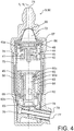
figure 4 est une représentation schématique partielle en coupe longitudinale d'un injecteur de carburant de la chambre de combustion selon l'invention, l'organe mobile d'étanchéité et l'organe mobile de dosage étant en position d'ouverture ; - la
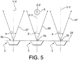
figure 5 est une représentation schématique partielle des nappes d'injection de carburant dans la chambre de combustion selon l'invention. - Des parties identiques, similaires ou équivalentes des différentes figures portent les mêmes références numériques de façon à faciliter le passage d'une figure à l'autre.
- La
figure 1 représente de manière schématique une chambre de combustion 2 d'une turbomachine d'aéronef. La chambre de combustion 2 est annulaire autour d'un axe longitudinal X-X de la turbomachine. - Elle comporte une paroi de carter extérieure 22 et une paroi de carter intérieure 23, un carénage 24, une paroi externe 25 et une paroi interne 26 qui sont réunies par un fond de chambre 28.
- Elle comprend également au moins une bougie d'allumage 6, des injecteurs 5a d'un premier type d'injecteurs qui sont situé en regard des bougies d'allumage 6, des injecteurs 5b d'un deuxième type d'injecteurs qui sont plus éloignés des bougies 6, des systèmes d'injection 3 et un diffuseur 7.
- La paroi de carter extérieure 22 délimite la chambre de combustion 2 radialement vers l'extérieur par rapport à l'axe longitudinal X-X de la turbomachine. La paroi de carter intérieure 23 délimite la chambre de combustion 2 radialement vers l'intérieur par rapport à l'axe longitudinal X-X de la turbomachine.
- La paroi de carter extérieure 22 délimite avec la paroi externe 25 un premier passage 11 d'écoulement d'air. De même, la paroi de carter intérieure 23 définit avec la paroi interne de chambre 26 un deuxième passage 12 d'écoulement d'air.
- Dans l'ensemble de l'exposé, une direction longitudinale est une direction qui est sensiblement parallèle à l'axe longitudinal X-X de la turbomachine. Une direction radiale est une direction qui est sensiblement orthogonale à l'axe longitudinal X-X de la turbomachine et qui est sécante avec cet axe. Une direction circonférentielle est une direction autour de l'axe longitudinal X-X de la turbomachine.
- Une direction « amont » et la direction « aval » sont définies par la direction générale d'écoulement de l'air et du carburant dans la chambre de combustion 2. Cette direction correspond également sensiblement à la direction générale d'écoulement des gaz d'échappement dans la turbomachine.
- La paroi externe 25 et la paroi interne 26 sont des parois de révolution qui sont coaxiales autour de l'axe longitudinal de turbomachine X-X, en étant symétriques par rapport à un axe longitudinal Y-Y du système d'injection 3 qui est représenté à la
figure 1 . Elles comprennent chacune des orifices primaires 81 d'introduction d'un flux d'air primaire et des orifices de dilution 82 d'introduction d'un flux d'air de dilution dans la chambre de combustion 2. - Le carénage 24 s'étend depuis la paroi externe 25 et la paroi interne 26 vers l'amont en étant situé en amont du fond de chambre 28. Il comporte des ouvertures centrales de logement des systèmes d'injection 3 et des injecteurs 5 correspondants.
- Le fond de chambre 28 comporte des ouvertures de montage des systèmes d'injection 3 dans desquels sont engagés les injecteurs de carburant 5.
- Chaque bougie d'allumage 6 est montée à travers la paroi externe 25 de la chambre de combustion. Elle s'étend transversalement à cette paroi en ayant son axe longitudinal Z-Z qui est sensiblement orthogonal à l'axe longitudinal Y-Y du système d'injection 3 de l'injecteur 5a du premier type qui est situé à proximité de cette bougie 6.
- La bougie d'allumage 6 sert à enflammer la nappe de mélange d'air et de carburant produite par l'injecteur 5a du premier type, pour que la flamme se propage ensuite aux nappes de mélange d'air et de carburant voisines qui sont produites par les injecteurs 5b de carburant du deuxième type, pour allumer la chambre de combustion 2.
- Les systèmes d'injection 3 sont montés sur le fond de chambre 28 en étant espacés les uns des autres selon une direction circonférentielle.
- Chaque système d'injection 3 comprend d'amont en aval une traversée coulissante 34, une vrille 32, un venturi 35, et un bol mélangeur 31. La traversée coulissante 34, la vrille 32 et le bol mélangeur 31 forment conjointement des moyens d'alimentation en air 30 pour produire une nappe de mélange air-carburant avec le carburant injecté par l'injecteur 5 correspondant.
- Dans le mode de réalisation représenté, les systèmes d'injection 3 des injecteurs 5a du premier type sont sensiblement identiques aux systèmes d'injection 3 des injecteurs 5b du deuxième type.
- Chaque système d'injection 3 est raccordé à un des injecteurs 5 de carburant qui est monté dans la traversée coulissante 34 au niveau d'un nez d'injecteur. La traversée coulissante 34 peut comporter des trous d'alimentation en air.
- La vrille 32 est montée solidaire du bol mélangeur 31. Elle comporte généralement un premier étage d'aubes et un deuxième étage d'aubes, qui ont pour fonction d'entraîner l'air en rotation autour de l'axe Y-Y du système d'injection 3. Les aubes du premier étage d'aubes de la vrille 32 peuvent tourner dans le même sens ou en sens contraire de celles du deuxième étage d'aubes de la vrille 32.
- Le bol mélangeur 31 présente une forme évasée sensiblement de révolution autour de l'axe longitudinal Y-Y du système d'injection 3. Il comprend des trous traversants pour alimenter la chambre de combustion 2 en air. Il est fixé au fond de chambre 28.
- Le diffuseur 7 est configuré pour alimenter la chambre de combustion 2, notamment les systèmes d'injection 3, les orifices primaires 81 et les orifices de dilution 82, en air chaud sous pression selon la flèche A.
- Cet air sous pression sert notamment à la combustion ou au refroidissement de la chambre de combustion 2. Une partie de cet air est introduit dans la chambre de combustion 2 au niveau de l'ouverture centrale du carénage 24, tandis qu'une autre partie de l'air s'écoule vers les passages 11 et 12 d'écoulement d'air. L'air alimentant le système d'injection 3 s'écoule depuis l'ouverture centrale du carénage 24, à travers notamment les aubes des vrilles 32 du système d'injection représenté à la
figure 1 et des trous traversants du bol mélangeur 31. L'écoulement d'air schématisé par les flèches 80 dans les passages 11 et 12 pénètre dans la chambre de combustion 2 par les orifices primaires 81 et les orifices de dilution 82. - En référence conjointe aux
figures 1 à 5 , chaque injecteur 5 est de type aéromécanique, c'est-à-dire que la pression du carburant à l'intérieur de l'injecteur 5 est utilisé pour pulvériser le carburant en sortie de l'injecteur 5. Il comporte un circuit primaire de carburant destiné par exemple à une phase d'allumage et de faible puissance, et un circuit secondaire intervenant dans les phases de fonctionnement ultérieures, de moyenne à forte puissance, en complément du circuit primaire. - Chaque injecteur 5 comprend d'amont en aval un corps 50 dont l'intérieur est représenté plus en détail aux
figures 2 à 4 , une platine de fixation 53, une canne d'injection 52 et un nez d'injecteur 54. - La platine de fixation 53 sert à fixer l'injecteur sur la paroi de carter extérieure 22. Le nez d'injecteur 54 comprend une buse de pulvérisation du carburant à son extrémité opposée à la canne d'injection 52. Il est destiné à engager la traversée coulissante 34. La canne d'injection 52 relie fluidiquement le corps 50 de l'injecteur au nez d'injecteur 54.
- En référence plus spécifiquement aux
figures 2 à 4 , le corps 50 d'injecteur comporte un enveloppe externe 56 creuse qui délimite l'injecteur radialement vers l'extérieur. Le corps 50 de l'injecteur est de révolution autour d'un axe longitudinal Y1-Y1 du corps 50 d'injecteur. - L'intérieur du corps 50 comprend une ouverture d'entrée de carburant 71, une crépine 55, un diaphragme 57, un organe mobile d'étanchéité 40, un organe mobile de dosage 60, un premier moyen élastique 44 de rappel, un deuxième moyen élastique 64 de rappel, une première sortie 76 de carburant, et une deuxième sortie 78 de carburant.
- L'intérieur du corps 50 d'injecteur comprend une partie fixe qui comprend l'enveloppe externe 56, la crépine 55, le diaphragme 57, un corps intermédiaire 58 qui est situé à l'intérieur de l'enveloppe externe 56 en s'étendant comme l'enveloppe externe 56 autour de l'axe longitudinal Y1-Y1 du corps d'injecteur, un siège 49 de l'organe d'étanchéité, un support 42 de l'organe mobile d'étanchéité, un support 62 de l'organe mobile de dosage, un conduit 77 d'alimentation du circuit primaire, et un conduit 79 d'alimentation du circuit secondaire.
- L'organe mobile d'étanchéité 40, le premier moyen élastique de rappel 44, l'organe mobile de dosage 60 et le deuxième moyen élastique de rappel 64 sont mobiles relativement à l'enveloppe externe 56, sous l'effet de la pression du carburant dans le corps 50.
- Le corps 50 d'injecteur comprend un orifice d'entrée 71 qui forme l'ouverture d'entrée de l'injecteur, une chambre d'entrée 72, une chambre d'admission 74, un espace primaire 45 qui est situé radialement entre le corps intermédiaire 58 et l'enveloppe externe 56 relativement à l'axe longitudinal Y1-Y1 du corps d'injecteur, une chambre intermédiaire 75 qui est située radialement relativement à l'axe longitudinal Yi-Yi entre le support 62 de l'organe mobile de dosage et le corps intermédiaire 58, un évidement central 60a de l'organe de dosage, au moins une fente 69 de dosage, et une chambre aval 65.
- L'orifice d'entrée 71 est une ouverture d'entrée de carburant dans l'injecteur 5. Il est destiné à recevoir le carburant sous pression provenant d'une pompe à carburant non représentée, ce carburant débouche ensuite dans la chambre d'entrée 72 après avoir traversé la crépine 55 de filtrage. Le diaphragme 57 est placé axialement entre la chambre d'entrée 72 et l'organe mobile d'étanchéité 40.
- La chambre d'admission 74 est située en aval de la chambre d'entrée 72 et elle est destinée à être séparée de cette dernière par l'organe mobile d'étanchéité 40. La chambre d'admission 74 communique fluidiquement avec l'espace primaire 45 qui débouche dans la première sortie 76 ou sortie primaire. La chambre d'admission 74 communique également fluidiquement avec la chambre intermédiaire 75 et avec l'évidement central 60a de l'organe de dosage.
- L'espace primaire 45 communique fluidiquement avec la première sortie 76 pour alimenter le circuit primaire de l'injecteur 5.
- L'organe mobile d'étanchéité 40 comporte une tête 40a et une tige 41. Il s'agit d'une soupape qui est également connue sous le nom de soupape d'arrêt.
- L'organe mobile d'étanchéité 40 est configuré pour être mobile entre une position d'ouverture dans laquelle il laisse passer du carburant en direction de la première sortie 76 et une position de fermeture dans laquelle il obture l'ouverture d'entrée 71.
- En position de fermeture qui est représentée à la
figure 2 , la tête 40a de l'organe mobile d'étanchéité est en appui contre son siège 49. En position d'ouverture qui est représentée à lafigure 3 et à lafigure 4 , la tête 40a de l'organe mobile d'étanchéité est abaissée relativement à son siège 49 pour laisser passer le carburant en direction de la chambre d'admission 74. - L'organe mobile d'étanchéité 40 est configuré pour s'ouvrir lorsque la pression carburant dépasse un seuil déterminé d'ouverture S1, S2 de l'organe mobile d'étanchéité 40. L'organe mobile d'étanchéité 40 de l'injecteur est configuré pour être ouvert lorsque la pression du carburant est supérieure au seuil d'ouverture S1, S2 de l'organe mobile d'étanchéité 40 de l'injecteur.
- Le seuil d'ouverture S1 de l'organe mobile d'étanchéité 40 de l'injecteur 5a du premier type, dit premier seuil d'ouverture S1, est strictement inférieur au seuil d'ouverture S2 de l'organe mobile d'étanchéité 40 de l'injecteur 5b du deuxième type, dit deuxième seuil d'ouverture S2.
- Le rapport de la valeur du deuxième seuil d'ouverture S2 sur la valeur du premier seuil d'ouverture S1 est compris entre 1,03 et 1,10.
- Le support de l'organe d'étanchéité 42 comprend une partie tubulaire dans laquelle est montée coulissante la tige 41 de l'organe mobile d'étanchéité 40. Le support de l'organe d'étanchéité 42 repose sur le corps intermédiaire 58 qui s'étend vers le bas et qui repose sur le support 62 de l'organe mobile de dosage.
- Le premier moyen élastique de rappel 44 comprend un ressort configuré pour être sollicité en compression. Ce ressort de compression est hélicoïdal. Le premier moyen élastique de rappel 44 prend appui sur la tête 40a de l'organe d'étanchéité et sur le support 42 de l'organe d'étanchéité. Le premier moyen élastique de rappel 44 est configuré pour solliciter l'organe mobile d'étanchéité 40 vers sa position de fermeture.
- Le premier moyen élastique de rappel 44 de l'injecteur 5a du premier type a notamment une raideur inférieure à la raideur du premier moyen élastique de rappel 44 de l'injecteur 5b du deuxième type.
- La chambre intermédiaire 75 est située en aval de la chambre d'admission 74. La chambre intermédiaire 75 est destinée à être séparée de la chambre aval 65 par l'organe mobile de dosage 60. La chambre intermédiaire 75 communique fluidiquement avec l'évidement central 60a de l'organe de dosage et avec les fentes 69 de dosage.
- La chambre aval 65 est située en aval l'organe de dosage mobile 60 et elle débouche dans la deuxième sortie 78 ou sortie secondaire qui alimente en carburant le circuit secondaire.
- L'organe mobile de dosage 60 comporte en outre une tête 60c et une portion tubulaire qui comprend l'évidement central 60a, des ouvertures radiales et un flanc inférieur 60b.
- La tête 60c de l'organe mobile de dosage 60 repose sur le deuxième moyen élastique de rappel 62.
- Les ouvertures radiales débouchent dans des fentes 69 de dosage. Ces fentes de dosage 69 sont délimitées radialement par rapport à l'axe longitudinal Y1-Y1 par la surface externe du flanc inférieur 60b et par la surface intérieure du support 62 de l'organe mobile de dosage. La géométrie des fentes 69 est telle que les sections de passage des fentes 69 varient en fonction de la position de l'organe mobile de dosage 60. En particulier, plus la pression du carburant dans la l'évidement central 60a est élevée, plus les sections de passage des fentes 69 sont grandes.
- L'organe mobile de dosage 60 est configuré pour être mobile entre une position d'ouverture dans laquelle il laisse passer du carburant en direction de la chambre aval 65 et une position de fermeture dans laquelle il obture la chambre aval 65.
- En position de fermeture qui est représentée à la
figure 3 , le deuxième moyen élastique de rappel 64 maintient le flanc inférieur 60b en appui contre une surface inférieure du support 62 de l'organe de dosage. Les fentes 69 de dosage ne débouchent pas dans la chambre aval 65. - En position d'ouverture qui est représentée à la
figure 4 , la tête 60c de l'organe mobile de dosage est en butée contre une surface supérieure du support 62 de l'organe mobile de dosage. Le flanc inférieur 60b de l'organe mobile de dosage est ainsi disposé de telle manière que les fentes 69 de dosage débouchent dans la chambre aval 65. - L'organe mobile de dosage 60 est configuré pour s'ouvrir lorsque la pression carburant dépasse un seuil déterminé d'ouverture S3 de l'organe mobile de dosage 60. Le seuil d'ouverture S3 de l'organe mobile de dosage 60 est strictement supérieur au seuil d'ouverture S1, S2 de l'organe mobile d'étanchéité 40 de l'injecteur correspondant. Plus généralement, le seuil d'ouverture S3 de l'organe mobile de dosage 60 est notamment strictement supérieur au seuil d'ouverture S1, S2 de chaque organe mobile d'étanchéité 40 des injecteurs de la chambre de combustion 2. L'organe mobile de dosage 60 est configuré pour être ouvert lorsque la pression du carburant est supérieure au seuil d'ouverture S3 de l'organe mobile de dosage 60.
- Le seuil d'ouverture S3 de l'organe mobile de dosage de l'injecteur 5a du premier type est sensiblement identique au seuil d'ouverture S3 de l'organe mobile de dosage 60 de l'injecteur 5b du deuxième type.
- Le support 62 de l'organe de dosage comprend une partie tubulaire dans un trou central 63 de laquelle est montée coulissante le flanc inférieur 60b de l'organe mobile de dosage 60. Le support de l'organe mobile de dosage 62 repose sur une embase qui délimite au moins partiellement la chambre aval 65.
- Le deuxième moyen élastique de rappel 64 comprend un ressort configuré pour être sollicité en compression. Ce ressort de compression est hélicoïdal. Ce ressort 64 est en contact de la tête 60c de l'organe de dosage et il s'appuie sur une surface radiale du support de l'organe mobile de dosage 62. Il est agencé autour du même axe longitudinal Y1-Y1 du corps d'injecteur que le premier moyen élastique de rappel 44. Le deuxième moyen élastique de rappel 64 est configuré pour solliciter l'organe mobile de dosage 60 vers sa position de fermeture.
- Le deuxième moyen élastique de rappel 64 de l'injecteur 5a du premier type a notamment une raideur sensiblement identique à la raideur du deuxième moyen élastique de rappel 64 de l'injecteur 5b du deuxième type.
- La deuxième sortie 78 débouche dans un conduit externe 79 qui est un conduit d'alimentation en carburant du circuit secondaire de l'injecteur 5.
- La première sortie 76 débouche dans un conduit interne 77 qui est un conduit d'alimentation en carburant du circuit primaire de l'injecteur 5. Ce conduit interne 77 est situé à l'intérieur du conduit d'alimentation 79 du circuit secondaire. L'espace annulaire qui est ménagé entre les deux conduits 77, 79 est destiné à être alimenté par du carburant qui alimente le circuit secondaire.
- En fonctionnement, plusieurs cas peuvent se présenter. Dans un premier cas, la pression du carburant dans la chambre d'entrée 72 est inférieure au seuil d'ouverture S1, S2 de l'organe mobile d'étanchéité 40. L'organe mobile d'étanchéité 40 est alors maintenu en position fermée par le ressort de rappel 44 et le carburant ne s'écoule ni à travers la première sortie 76, ni à travers la deuxième sortie 78.
- Dans un deuxième cas, correspondant à une phase d'allumage ou de fonctionnement à bas régime, la pression du carburant dans la chambre d'entrée 72 est supérieure au seuil d'ouverture S1, S2 de l'organe mobile d'étanchéité 40, mais la pression du carburant dans la chambre intermédiaire 75 est inférieure au seuil d'ouverture S3 de l'organe mobile de dosage 60. L'organe mobile d'étanchéité 40 est alors ouvert et le carburant peut s'écouler dans l'espace primaire 45 puis à travers la première sortie 76. L'organe mobile de dosage 60 reste toutefois fermé, et le carburant ne s'écoule pas à travers la deuxième sortie 78.
- Dans un troisième cas, correspondant à une phase de fonctionnement à moyen ou à plein régime, la pression du carburant dans la chambre d'entrée 72 est supérieure au seuil d'ouverture S1, S2 de l'organe mobile d'étanchéité 40 et la pression du carburant dans la chambre intermédiaire 75 est supérieure seuil d'ouverture S3 de l'organe mobile de dosage 60. L'organe mobile d'étanchéité 40 est ouvert et le carburant peut s'écouler dans l'espace primaire 45 puis à travers la première sortie 76. En outre, l'organe mobile de dosage 60 est également ouvert et le fluide peut s'écouler au travers de la chambre intermédiaire 75, de l'évidement central 60a, des fentes 69, de la chambre aval 65 puis de la deuxième sortie 78.
- En référence à la
figure 5 , le débit de carburant injecté par chaque injecteur 5a du premier type est sensiblement identique au débit de carburant injecté par chaque injecteur 5b du deuxième type, au moins en régime permanent. - Le débit d'air d'alimentation des systèmes d'injection 3 des injecteurs 5a du premier type est sensiblement identique à celui des systèmes d'injection 3 des injecteurs 5b du deuxième type.
- Chaque injecteur 5a du premier type est configuré pour injecter du carburant qui forme une nappe 86 de mélange d'air et de carburant de mélange d'air et de carburant conique en s'ouvrant vers l'aval. Cette nappe 86 présentant un angle d'ouverture β centré sur l'axe longitudinal Y-Y du système d'injection correspondant et en direction des injecteurs 5 adjacents.
- Chaque injecteur 5b du deuxième type est configuré pour injecter du carburant qui forme une nappe 87 de mélange d'air et de carburant conique en s'ouvrant vers l'aval. Cette nappe 87 présentant un angle d'ouverture α centré sur l'axe longitudinal Y-Y du système d'injection correspondant et en direction des injecteurs 5 adjacents.
- L'angle d'ouverture β des nappes 86 de mélange air-carburant en provenance des injecteurs 5a du premier type est sensiblement égal à l'angle d'ouverture α des nappes 87 de mélange air-carburant en provenance des injecteurs 5b du deuxième type.
- Il découle de l'égalité des débits entre les différents injecteurs 5a, 5b et de l'égalité des angles d'ouvertures a, β des nappes une répartition plus homogène du carburant dans la chambre de combustion 2 et une réduction des hétérogénéités de température dans la chambre de combustion 2.
- De manière générale, le seuil d'ouverture Si inférieur de l'organe mobile d'étanchéité 40 de chaque injecteur 5a du premier type par rapport au seuil d'ouverture S2 de l'organe mobile d'étanchéité 40 de chaque injecteur 5b du deuxième type tend à limiter les pertes de charges du carburant dans les injecteurs 5a du premier type.
- La différence de pression entre la pression du carburant arrivant dans l'ouverture d'entrée 71 d'un injecteur 5a du premier type et la pression du carburant traversant la deuxième sortie 78 de cet injecteur tend à être supérieure. La taille des gouttes de carburant injecté à proximité des bougies d'allumage 6 tend à réduire. Il en découle un meilleur mélange d'air et de carburant injecté dans la chambre de combustion 2. Le rallumage en vol de la chambre de combustion 2 est alors facilité.
- Le seuil d'ouverture S2 de l'organe d'étanchéité de chaque injecteur 5b du deuxième type est laissé inchangé. Or, le nombre d'injecteurs 5b du deuxième type est très supérieur à celui des injecteurs 5a du premier type, du fait du faible nombre de bougies 6 d'allumage dans les turbomachines 1 modernes. L'abaissement du seuil d'ouverture S1 de l'organe mobile d'étanchéité 40 de chaque injecteur 5a du premier type a donc relativement peu d'influence sur le système d'alimentation en carburant des injecteurs 5. Par conséquent, la chambre de combustion 2 tend à être rallumée plus facilement avec des modifications assez limitées de la turbomachine et en particulier de son système d'alimentation en carburant.
- Bien entendu, diverses modifications peuvent être apportées par l'homme du métier à l'invention qui vient d'être décrite sans sortir du cadre de l'exposé de l'invention.
- En variante, le débit de carburant injecté par chaque injecteur 5a du premier type est strictement supérieur au débit de carburant injecté par chaque injecteur 5b du deuxième type, pour faciliter encore le rallumage en vol de la chambre de combustion 2.
- Dans ce cas, le seuil d'ouverture S3 de l'organe mobile de dosage 60 de chaque injecteur 5a du premier type est notamment strictement inférieur à celui de l'organe mobile de dosage 60 de chaque injecteur 5b du deuxième type. En plus ou en variante, le nez d'injecteur 54 de chaque injecteur 5a du premier type présente un orifice de sortie de plus grand diamètre que celui de chaque injecteur 5b du deuxième type.
Claims (9)
- Chambre de combustion (2) pour turbomachine, comprenant :au moins une bougie d'allumage (6),au moins un injecteur (5) de carburant d'un premier type (5a), situé en regard de la bougie d'allumage (6),au moins un injecteur (5) de carburant d'un deuxième type (5b), plus éloigné de la bougie d'allumage (6) que l'injecteur du premier type (5a),chaque injecteur (5) de carburant comprenant :une ouverture d'entrée (71) de carburant,une première sortie (76) de carburant,un organe mobile d'étanchéité (40) configuré pour être mobile entre une position d'ouverture dans laquelle il laisse passer du carburant en direction de la première sortie (76) et une position de fermeture dans laquelle il obture l'ouverture d'entrée (71), l'organe mobile d'étanchéité (40) étant configuré pour s'ouvrir lorsque la pression carburant appliquée à l'organe mobile d'étanchéité dépasse un seuil d'ouverture (S1) de l'organe mobile d'étanchéité (40), etun premier moyen élastique de rappel (44) configuré pour solliciter l'organe mobile d'étanchéité (40) vers sa position de fermeture, etcaractérisé en ce que le seuil d'ouverture (S1) de l'organe mobile d'étanchéité (40) de l'injecteur (5a) du premier type, dit premier seuil d'ouverture (S1), est strictement inférieur au seuil d'ouverture (S2) de l'organe mobile d'étanchéité (40) de l'injecteur (5b) du deuxième type, dit deuxième seuil d'ouverture (S2).
- Chambre de combustion (2) pour turbomachine selon la revendication précédente, dans laquelle l'injecteur (5a) du premier type et/ou l'injecteur (5b) du deuxième type comprend :une deuxième sortie (78) de carburant, etun organe mobile de dosage (60) configuré pour être mobile entre une position d'ouverture dans laquelle il laisse passer du carburant en direction de la deuxième sortie (78) et une position de fermeture dans laquelle il empêche la circulation de carburant vers la deuxième sortie (78),un deuxième moyen élastique de rappel (64) configuré pour solliciter l'organe mobile de dosage (60) vers sa position de fermeture,l'organe mobile de dosage (60) étant configuré pour s'ouvrir lorsque la pression carburant dépasse un seuil d'ouverture (S3) de l'organe mobile de dosage (60) qui est supérieur au seuil d'ouverture (S1, S2) de l'organe mobile d'étanchéité (40) de l'injecteur,
la première sortie (76) communiquant fluidiquement avec un circuit primaire de l'injecteur, la deuxième sortie (78) communiquant fluidiquement avec un circuit secondaire de l'injecteur. - Chambre de combustion (2) pour turbomachine selon la revendication précédente, dans laquelle l'organe mobile d'étanchéité (40) de l'injecteur du premier type et/ou de l'injecteur du deuxième type est configuré pour être ouvert lorsque la pression du carburant est supérieure au seuil d'ouverture (S1, S2) de l'organe mobile d'étanchéité (40) de l'injecteur, pour permettre au carburant d'alimenter le circuit primaire à travers la première sortie (76),
l'organe mobile de dosage (60) de l'injecteur est configuré pour être ouvert lorsque la pression du carburant est supérieure au seuil d'ouverture (S3) de l'organe mobile de dosage (60), pour permettre au carburant d'alimenter le circuit secondaire de l'injecteur à travers la deuxième sortie (78). - Chambre de combustion (2) pour turbomachine selon l'une quelconque des revendications 2 et 3, dans laquelle le premier moyen élastique de rappel (44) de l'injecteur (5a) du premier type a une raideur inférieure à la raideur du premier moyen élastique de rappel (44) de l'injecteur (5b) du deuxième type,
le premier moyen élastique de rappel (44) comprenant de préférence un ressort, et/ou le deuxième moyen élastique de rappel (64) comprenant de préférence un ressort,
le premier moyen élastique de rappel (44) et le deuxième moyen élastique de rappel (64) étant de préférence agencés autour d'un même axe longitudinal (Y1-Y1) de l'injecteur. - Chambre de combustion (2) pour turbomachine selon l'une quelconque des revendications 2 à 4, dans laquelle le seuil d'ouverture (S3) de l'organe de dosage de l'injecteur (5a) du premier type est identique au seuil d'ouverture (S3) de l'organe de dosage de l'injecteur (5b) du deuxième type, et/ou
dans lequel l'injecteur (5a) du premier type est configuré pour injecter en régime permanent un débit de carburant qui est sensiblement identique au débit de carburant injecté par l'injecteur (5b) du deuxième type. - Chambre de combustion (2) pour turbomachine selon l'une quelconque des revendications précédentes, dans laquelle le rapport de la valeur du deuxième seuil d'ouverture (S2) sur la valeur du premier seuil d'ouverture (S1) est compris entre 1,03 et 1,10.
- Chambre de combustion (2) pour turbomachine selon l'une quelconque des revendications précédentes, dans laquelle l'injecteur (5a) du premier type est configuré pour injecter du carburant selon une nappe (86) ayant un angle d'ouverture (β) qui est sensiblement égal à un angle d'ouverture (α) d'une nappe (87) de carburant destinée à être injectée par l'injecteur (5b) du deuxième type.
- Chambre de combustion (2) pour turbomachine selon l'une quelconque des revendications précédentes, comprenant un premier système d'injection (3) dans lequel est engagé l'injecteur du premier type (5a), et un deuxième système d'injection (3) dans lequel est engagé l'injecteur (5b) du deuxième type, chaque système d'injection (3) comprenant au moins une vrille (32) d'air et un bol mélangeur (31),
le premier système d'injection (3) étant sensiblement identique au deuxième système d'injection (3). - Turbomachine comprenant une chambre de combustion (2) selon l'une quelconque des revendications précédentes, la turbomachine étant de préférence une turbomachine d'aéronef.
Applications Claiming Priority (1)
| Application Number | Priority Date | Filing Date | Title |
|---|---|---|---|
| FR1851551A FR3078142B1 (fr) | 2018-02-22 | 2018-02-22 | Chambre de combustion comportant deux types d'injecteurs dans lesquels les organes d'etancheite ont un seuil d'ouverture different |
Publications (2)
| Publication Number | Publication Date |
|---|---|
| EP3530908A1 EP3530908A1 (fr) | 2019-08-28 |
| EP3530908B1 true EP3530908B1 (fr) | 2020-07-29 |
Family
ID=62143370
Family Applications (1)
| Application Number | Title | Priority Date | Filing Date |
|---|---|---|---|
| EP19158266.7A Active EP3530908B1 (fr) | 2018-02-22 | 2019-02-20 | Chambre de combustion comportant deux types d'injecteurs dans lesquels les organes d'étanchéité ont un seuil d'ouverture différent |
Country Status (4)
| Country | Link |
|---|---|
| US (1) | US11002196B2 (fr) |
| EP (1) | EP3530908B1 (fr) |
| CN (1) | CN110186068A (fr) |
| FR (1) | FR3078142B1 (fr) |
Families Citing this family (4)
| Publication number | Priority date | Publication date | Assignee | Title |
|---|---|---|---|---|
| FR3091332B1 (fr) | 2018-12-27 | 2021-01-29 | Safran Aircraft Engines | Nez d’injecteur pour turbomachine comprenant une vrille secondaire de carburant à section évolutive |
| US11346281B2 (en) * | 2020-08-21 | 2022-05-31 | Woodward, Inc. | Dual schedule flow divider valve, system, and method for use therein |
| US11466859B2 (en) * | 2020-12-18 | 2022-10-11 | Pratt & Whitney Canada Corp. | Gap filler for a fuel system gallery |
| US20220205637A1 (en) * | 2020-12-30 | 2022-06-30 | General Electric Company | Mitigating combustion dynamics using varying liquid fuel cartridges |
Family Cites Families (18)
| Publication number | Priority date | Publication date | Assignee | Title |
|---|---|---|---|---|
| US4817389A (en) * | 1987-09-24 | 1989-04-04 | United Technologies Corporation | Fuel injection system |
| US5167122A (en) * | 1991-04-30 | 1992-12-01 | Sundstrand Corporation | Fuel system for a turbo machine |
| US5402634A (en) * | 1993-10-22 | 1995-04-04 | United Technologies Corporation | Fuel supply system for a staged combustor |
| FR2832492B1 (fr) * | 2001-11-20 | 2004-02-06 | Snecma Moteurs | Perfectionnements apportes aux injecteurs de turbomachine |
| JP2006257943A (ja) * | 2005-03-16 | 2006-09-28 | Mazda Motor Corp | 火花点火式直噴エンジン |
| FR2911665B1 (fr) * | 2007-01-22 | 2009-04-17 | Hispano Suiza Sa | Injecteur de carburant a deux etages. |
| FR2922995B1 (fr) * | 2007-10-31 | 2009-12-04 | Snecma | Chambre de combustion annulaire de moteur a turbine a gaz. |
| FR2943119B1 (fr) * | 2009-03-12 | 2011-03-25 | Snecma | Systemes d'injection de carburant dans une chambre de combustion de turbomachine |
| JP4785973B2 (ja) * | 2010-02-02 | 2011-10-05 | 川崎重工業株式会社 | ガスタービンエンジンの燃料供給装置 |
| JP4815537B1 (ja) * | 2010-04-23 | 2011-11-16 | 川崎重工業株式会社 | ガスタービンエンジンの燃料供給装置 |
| FR2962491B1 (fr) * | 2010-07-07 | 2014-04-04 | Snecma | Procedure d'allumage pour une chambre de combustion de turbomachine |
| FR3002284B1 (fr) * | 2013-02-18 | 2015-02-13 | Turbomeca | Procede de surveillance d'un degre de colmatage d'injecteurs de demarrage d'une turbomachine |
| FR3003013B1 (fr) * | 2013-03-05 | 2016-07-29 | Snecma | Dispositif de dosage compact pour injecteur a deux circuits de carburant, de preference pour turbomachine d'aeronef |
| FR3011619B1 (fr) * | 2013-10-08 | 2018-03-02 | Safran Aircraft Engines | Injecteur de carburant pour une turbomachine |
| CN103697498A (zh) * | 2013-12-13 | 2014-04-02 | 中国燃气涡轮研究院 | 一种提高燃烧室点火性能的供油方法 |
| FR3025017B1 (fr) | 2014-08-20 | 2016-09-30 | Snecma | Dispositif de raccordement comportant plusieurs tubes concentriques cintres |
| FR3027059B1 (fr) * | 2014-10-13 | 2019-08-30 | Safran Helicopter Engines | Systeme d'allumage d'une chambre de combustion d'un turbomoteur |
| FR3031799B1 (fr) | 2015-01-19 | 2017-02-17 | Snecma | Dispositif d'etancheite ameliore entre un systeme d'injection et un nez d'injecteur de carburant de turbomachine d'aeronef |
-
2018
- 2018-02-22 FR FR1851551A patent/FR3078142B1/fr active Active
-
2019
- 2019-02-20 EP EP19158266.7A patent/EP3530908B1/fr active Active
- 2019-02-21 US US16/281,308 patent/US11002196B2/en active Active
- 2019-02-22 CN CN201910133168.2A patent/CN110186068A/zh active Pending
Non-Patent Citations (1)
| Title |
|---|
| None * |
Also Published As
| Publication number | Publication date |
|---|---|
| US20190257251A1 (en) | 2019-08-22 |
| FR3078142B1 (fr) | 2020-03-20 |
| EP3530908A1 (fr) | 2019-08-28 |
| FR3078142A1 (fr) | 2019-08-23 |
| CN110186068A (zh) | 2019-08-30 |
| US11002196B2 (en) | 2021-05-11 |
Similar Documents
| Publication | Publication Date | Title |
|---|---|---|
| CA2646959C (fr) | Systeme d'injection d'un melange d'air et de carburant dans une chambre de combustion de turbomachine | |
| EP3530908B1 (fr) | Chambre de combustion comportant deux types d'injecteurs dans lesquels les organes d'étanchéité ont un seuil d'ouverture différent | |
| EP1793168B1 (fr) | Dispositif d'injection d'un mélange d'air et de carburant, chambre de combustion et turbomachine munies d'un tel dispositif | |
| CA2864629C (fr) | Injecteur de carburant pour une turbomachine | |
| FR2931203A1 (fr) | Injecteur de carburant pour turbine a gaz et son procede de fabrication | |
| FR2903169A1 (fr) | Dispositif d'injection d'un melange d'air et de carburant, chambre de combustion et turbomachine munies d'un tel dispositif | |
| EP1278012A2 (fr) | Système d'injection aéromécanique à vrille primaire anti-retour | |
| CA2848629A1 (fr) | Chambre annulaire de combustion d'une turbomachine | |
| FR2602009A1 (fr) | Injecteur de carburant a air pulse muni d'une valve monobloc elastique en porte-a-faux regulatrice du debit de carburant, procede de fabrication dudit injecteur, et procede pour diminuer un bouchon de vapeur resultant d'une haute temperature | |
| CA2925441C (fr) | Chambre de combustion pour turbomachine a admission d'air homogene au travers de systemes d'injection de carburant | |
| WO2020144416A1 (fr) | Systeme d'injection pour turbomachine, comprenant une vrille et des trous tourbillonnaires de bol melangeur | |
| EP3578884A1 (fr) | Chambre de combustion pour une turbomachine | |
| FR3039254A1 (fr) | Chambre de combustion comportant des dispositifs d'injection additionnels debouchant directement dans les zones de recirculation de coin, turbomachine la comprenant, et procede d'alimentation en carburant de celle-ci | |
| EP3784958B1 (fr) | Système d'injection pour une chambre annulaire de combustion de turbomachine | |
| EP1770333B1 (fr) | Bras d'injecteur anti-cokéfaction | |
| FR2958015A1 (fr) | Systeme d'injection pour chambre de combustion de turbomachine, comprenant des moyens d'injection de carburant entre deux flux d'air coaxiaux | |
| FR2943119A1 (fr) | Systemes d'injection de carburant dans une chambre de combustion de turbomachine | |
| CA2850259C (fr) | Chambre de combustion annulaire dans une turbomachine | |
| FR3033030A1 (fr) | Systeme d'injection d'un melange air-carburant dans une chambre de combustion de turbomachine d'aeronef, comprenant un venturi perfore de trous d'injection d'air | |
| FR3141755A1 (fr) | Chambre de combustion d’une turbomachine | |
| WO2024261434A1 (fr) | Systeme d'injection pour chambre de combustion de turbomachine a etancheite optimisee entre injecteur et traversee coulissante | |
| FR3162501A1 (fr) | Injecteur ondulé de dispositif d’injection pour chambre de combustion | |
| FR3150268A1 (fr) | Système d’injection pour chambre de combustion de turbomachine ayant des trous de purge optimisés | |
| FR3107570A1 (fr) | Brûleur de postcombustion a integration optimisée | |
| FR2626937A1 (fr) | Bruleur de carburant pour turbine a gaz |
Legal Events
| Date | Code | Title | Description |
|---|---|---|---|
| PUAI | Public reference made under article 153(3) epc to a published international application that has entered the european phase |
Free format text: ORIGINAL CODE: 0009012 |
|
| STAA | Information on the status of an ep patent application or granted ep patent |
Free format text: STATUS: THE APPLICATION HAS BEEN PUBLISHED |
|
| AK | Designated contracting states |
Kind code of ref document: A1 Designated state(s): AL AT BE BG CH CY CZ DE DK EE ES FI FR GB GR HR HU IE IS IT LI LT LU LV MC MK MT NL NO PL PT RO RS SE SI SK SM TR |
|
| AX | Request for extension of the european patent |
Extension state: BA ME |
|
| STAA | Information on the status of an ep patent application or granted ep patent |
Free format text: STATUS: REQUEST FOR EXAMINATION WAS MADE |
|
| 17P | Request for examination filed |
Effective date: 20190916 |
|
| RBV | Designated contracting states (corrected) |
Designated state(s): AL AT BE BG CH CY CZ DE DK EE ES FI FR GB GR HR HU IE IS IT LI LT LU LV MC MK MT NL NO PL PT RO RS SE SI SK SM TR |
|
| GRAP | Despatch of communication of intention to grant a patent |
Free format text: ORIGINAL CODE: EPIDOSNIGR1 |
|
| STAA | Information on the status of an ep patent application or granted ep patent |
Free format text: STATUS: GRANT OF PATENT IS INTENDED |
|
| INTG | Intention to grant announced |
Effective date: 20200128 |
|
| GRAS | Grant fee paid |
Free format text: ORIGINAL CODE: EPIDOSNIGR3 |
|
| GRAA | (expected) grant |
Free format text: ORIGINAL CODE: 0009210 |
|
| STAA | Information on the status of an ep patent application or granted ep patent |
Free format text: STATUS: THE PATENT HAS BEEN GRANTED |
|
| AK | Designated contracting states |
Kind code of ref document: B1 Designated state(s): AL AT BE BG CH CY CZ DE DK EE ES FI FR GB GR HR HU IE IS IT LI LT LU LV MC MK MT NL NO PL PT RO RS SE SI SK SM TR |
|
| REG | Reference to a national code |
Ref country code: CH Ref legal event code: EP |
|
| REG | Reference to a national code |
Ref country code: AT Ref legal event code: REF Ref document number: 1296073 Country of ref document: AT Kind code of ref document: T Effective date: 20200815 |
|
| REG | Reference to a national code |
Ref country code: IE Ref legal event code: FG4D Free format text: LANGUAGE OF EP DOCUMENT: FRENCH |
|
| REG | Reference to a national code |
Ref country code: DE Ref legal event code: R096 Ref document number: 602019000337 Country of ref document: DE |
|
| REG | Reference to a national code |
Ref country code: SE Ref legal event code: TRGR |
|
| REG | Reference to a national code |
Ref country code: LT Ref legal event code: MG4D |
|
| REG | Reference to a national code |
Ref country code: NL Ref legal event code: MP Effective date: 20200729 |
|
| REG | Reference to a national code |
Ref country code: AT Ref legal event code: MK05 Ref document number: 1296073 Country of ref document: AT Kind code of ref document: T Effective date: 20200729 |
|
| PG25 | Lapsed in a contracting state [announced via postgrant information from national office to epo] |
Ref country code: FI Free format text: LAPSE BECAUSE OF FAILURE TO SUBMIT A TRANSLATION OF THE DESCRIPTION OR TO PAY THE FEE WITHIN THE PRESCRIBED TIME-LIMIT Effective date: 20200729 Ref country code: GR Free format text: LAPSE BECAUSE OF FAILURE TO SUBMIT A TRANSLATION OF THE DESCRIPTION OR TO PAY THE FEE WITHIN THE PRESCRIBED TIME-LIMIT Effective date: 20201030 Ref country code: LT Free format text: LAPSE BECAUSE OF FAILURE TO SUBMIT A TRANSLATION OF THE DESCRIPTION OR TO PAY THE FEE WITHIN THE PRESCRIBED TIME-LIMIT Effective date: 20200729 Ref country code: PT Free format text: LAPSE BECAUSE OF FAILURE TO SUBMIT A TRANSLATION OF THE DESCRIPTION OR TO PAY THE FEE WITHIN THE PRESCRIBED TIME-LIMIT Effective date: 20201130 Ref country code: HR Free format text: LAPSE BECAUSE OF FAILURE TO SUBMIT A TRANSLATION OF THE DESCRIPTION OR TO PAY THE FEE WITHIN THE PRESCRIBED TIME-LIMIT Effective date: 20200729 Ref country code: ES Free format text: LAPSE BECAUSE OF FAILURE TO SUBMIT A TRANSLATION OF THE DESCRIPTION OR TO PAY THE FEE WITHIN THE PRESCRIBED TIME-LIMIT Effective date: 20200729 Ref country code: BG Free format text: LAPSE BECAUSE OF FAILURE TO SUBMIT A TRANSLATION OF THE DESCRIPTION OR TO PAY THE FEE WITHIN THE PRESCRIBED TIME-LIMIT Effective date: 20201029 Ref country code: AT Free format text: LAPSE BECAUSE OF FAILURE TO SUBMIT A TRANSLATION OF THE DESCRIPTION OR TO PAY THE FEE WITHIN THE PRESCRIBED TIME-LIMIT Effective date: 20200729 Ref country code: NO Free format text: LAPSE BECAUSE OF FAILURE TO SUBMIT A TRANSLATION OF THE DESCRIPTION OR TO PAY THE FEE WITHIN THE PRESCRIBED TIME-LIMIT Effective date: 20201029 |
|
| PG25 | Lapsed in a contracting state [announced via postgrant information from national office to epo] |
Ref country code: PL Free format text: LAPSE BECAUSE OF FAILURE TO SUBMIT A TRANSLATION OF THE DESCRIPTION OR TO PAY THE FEE WITHIN THE PRESCRIBED TIME-LIMIT Effective date: 20200729 Ref country code: RS Free format text: LAPSE BECAUSE OF FAILURE TO SUBMIT A TRANSLATION OF THE DESCRIPTION OR TO PAY THE FEE WITHIN THE PRESCRIBED TIME-LIMIT Effective date: 20200729 Ref country code: LV Free format text: LAPSE BECAUSE OF FAILURE TO SUBMIT A TRANSLATION OF THE DESCRIPTION OR TO PAY THE FEE WITHIN THE PRESCRIBED TIME-LIMIT Effective date: 20200729 Ref country code: IS Free format text: LAPSE BECAUSE OF FAILURE TO SUBMIT A TRANSLATION OF THE DESCRIPTION OR TO PAY THE FEE WITHIN THE PRESCRIBED TIME-LIMIT Effective date: 20201129 |
|
| PG25 | Lapsed in a contracting state [announced via postgrant information from national office to epo] |
Ref country code: NL Free format text: LAPSE BECAUSE OF FAILURE TO SUBMIT A TRANSLATION OF THE DESCRIPTION OR TO PAY THE FEE WITHIN THE PRESCRIBED TIME-LIMIT Effective date: 20200729 |
|
| PG25 | Lapsed in a contracting state [announced via postgrant information from national office to epo] |
Ref country code: SM Free format text: LAPSE BECAUSE OF FAILURE TO SUBMIT A TRANSLATION OF THE DESCRIPTION OR TO PAY THE FEE WITHIN THE PRESCRIBED TIME-LIMIT Effective date: 20200729 Ref country code: RO Free format text: LAPSE BECAUSE OF FAILURE TO SUBMIT A TRANSLATION OF THE DESCRIPTION OR TO PAY THE FEE WITHIN THE PRESCRIBED TIME-LIMIT Effective date: 20200729 Ref country code: CZ Free format text: LAPSE BECAUSE OF FAILURE TO SUBMIT A TRANSLATION OF THE DESCRIPTION OR TO PAY THE FEE WITHIN THE PRESCRIBED TIME-LIMIT Effective date: 20200729 Ref country code: DK Free format text: LAPSE BECAUSE OF FAILURE TO SUBMIT A TRANSLATION OF THE DESCRIPTION OR TO PAY THE FEE WITHIN THE PRESCRIBED TIME-LIMIT Effective date: 20200729 Ref country code: EE Free format text: LAPSE BECAUSE OF FAILURE TO SUBMIT A TRANSLATION OF THE DESCRIPTION OR TO PAY THE FEE WITHIN THE PRESCRIBED TIME-LIMIT Effective date: 20200729 |
|
| REG | Reference to a national code |
Ref country code: DE Ref legal event code: R097 Ref document number: 602019000337 Country of ref document: DE |
|
| PG25 | Lapsed in a contracting state [announced via postgrant information from national office to epo] |
Ref country code: AL Free format text: LAPSE BECAUSE OF FAILURE TO SUBMIT A TRANSLATION OF THE DESCRIPTION OR TO PAY THE FEE WITHIN THE PRESCRIBED TIME-LIMIT Effective date: 20200729 |
|
| PLBE | No opposition filed within time limit |
Free format text: ORIGINAL CODE: 0009261 |
|
| STAA | Information on the status of an ep patent application or granted ep patent |
Free format text: STATUS: NO OPPOSITION FILED WITHIN TIME LIMIT |
|
| PG25 | Lapsed in a contracting state [announced via postgrant information from national office to epo] |
Ref country code: SK Free format text: LAPSE BECAUSE OF FAILURE TO SUBMIT A TRANSLATION OF THE DESCRIPTION OR TO PAY THE FEE WITHIN THE PRESCRIBED TIME-LIMIT Effective date: 20200729 |
|
| 26N | No opposition filed |
Effective date: 20210430 |
|
| PG25 | Lapsed in a contracting state [announced via postgrant information from national office to epo] |
Ref country code: SI Free format text: LAPSE BECAUSE OF FAILURE TO SUBMIT A TRANSLATION OF THE DESCRIPTION OR TO PAY THE FEE WITHIN THE PRESCRIBED TIME-LIMIT Effective date: 20200729 |
|
| PG25 | Lapsed in a contracting state [announced via postgrant information from national office to epo] |
Ref country code: MC Free format text: LAPSE BECAUSE OF FAILURE TO SUBMIT A TRANSLATION OF THE DESCRIPTION OR TO PAY THE FEE WITHIN THE PRESCRIBED TIME-LIMIT Effective date: 20200729 |
|
| REG | Reference to a national code |
Ref country code: BE Ref legal event code: MM Effective date: 20210228 |
|
| PG25 | Lapsed in a contracting state [announced via postgrant information from national office to epo] |
Ref country code: LU Free format text: LAPSE BECAUSE OF NON-PAYMENT OF DUE FEES Effective date: 20210220 |
|
| PG25 | Lapsed in a contracting state [announced via postgrant information from national office to epo] |
Ref country code: IE Free format text: LAPSE BECAUSE OF NON-PAYMENT OF DUE FEES Effective date: 20210220 |
|
| PG25 | Lapsed in a contracting state [announced via postgrant information from national office to epo] |
Ref country code: BE Free format text: LAPSE BECAUSE OF NON-PAYMENT OF DUE FEES Effective date: 20210228 |
|
| REG | Reference to a national code |
Ref country code: CH Ref legal event code: PL |
|
| PG25 | Lapsed in a contracting state [announced via postgrant information from national office to epo] |
Ref country code: LI Free format text: LAPSE BECAUSE OF NON-PAYMENT OF DUE FEES Effective date: 20220228 Ref country code: CH Free format text: LAPSE BECAUSE OF NON-PAYMENT OF DUE FEES Effective date: 20220228 |
|
| PG25 | Lapsed in a contracting state [announced via postgrant information from national office to epo] |
Ref country code: CY Free format text: LAPSE BECAUSE OF FAILURE TO SUBMIT A TRANSLATION OF THE DESCRIPTION OR TO PAY THE FEE WITHIN THE PRESCRIBED TIME-LIMIT Effective date: 20200729 |
|
| PG25 | Lapsed in a contracting state [announced via postgrant information from national office to epo] |
Ref country code: HU Free format text: LAPSE BECAUSE OF FAILURE TO SUBMIT A TRANSLATION OF THE DESCRIPTION OR TO PAY THE FEE WITHIN THE PRESCRIBED TIME-LIMIT; INVALID AB INITIO Effective date: 20190220 |
|
| PG25 | Lapsed in a contracting state [announced via postgrant information from national office to epo] |
Ref country code: MK Free format text: LAPSE BECAUSE OF FAILURE TO SUBMIT A TRANSLATION OF THE DESCRIPTION OR TO PAY THE FEE WITHIN THE PRESCRIBED TIME-LIMIT Effective date: 20200729 |
|
| PG25 | Lapsed in a contracting state [announced via postgrant information from national office to epo] |
Ref country code: MT Free format text: LAPSE BECAUSE OF FAILURE TO SUBMIT A TRANSLATION OF THE DESCRIPTION OR TO PAY THE FEE WITHIN THE PRESCRIBED TIME-LIMIT Effective date: 20200729 |
|
| PG25 | Lapsed in a contracting state [announced via postgrant information from national office to epo] |
Ref country code: TR Free format text: LAPSE BECAUSE OF FAILURE TO SUBMIT A TRANSLATION OF THE DESCRIPTION OR TO PAY THE FEE WITHIN THE PRESCRIBED TIME-LIMIT Effective date: 20200729 |
|
| PGFP | Annual fee paid to national office [announced via postgrant information from national office to epo] |
Ref country code: SE Payment date: 20260218 Year of fee payment: 8 |
|
| PGFP | Annual fee paid to national office [announced via postgrant information from national office to epo] |
Ref country code: GB Payment date: 20260219 Year of fee payment: 8 |
|
| PGFP | Annual fee paid to national office [announced via postgrant information from national office to epo] |
Ref country code: DE Payment date: 20260217 Year of fee payment: 8 |
|
| PGFP | Annual fee paid to national office [announced via postgrant information from national office to epo] |
Ref country code: IT Payment date: 20260227 Year of fee payment: 8 |
|
| PGFP | Annual fee paid to national office [announced via postgrant information from national office to epo] |
Ref country code: FR Payment date: 20260219 Year of fee payment: 8 |