EP3530865B1 - Assembly station for venetian blinds with complete support ladders - Google Patents
Assembly station for venetian blinds with complete support ladders Download PDFInfo
- Publication number
- EP3530865B1 EP3530865B1 EP19154093.9A EP19154093A EP3530865B1 EP 3530865 B1 EP3530865 B1 EP 3530865B1 EP 19154093 A EP19154093 A EP 19154093A EP 3530865 B1 EP3530865 B1 EP 3530865B1
- Authority
- EP
- European Patent Office
- Prior art keywords
- stop device
- end stop
- slat
- insertion axis
- sliding
- Prior art date
- Legal status (The legal status is an assumption and is not a legal conclusion. Google has not performed a legal analysis and makes no representation as to the accuracy of the status listed.)
- Active
Links
Images


Classifications
-
- E—FIXED CONSTRUCTIONS
- E06—DOORS, WINDOWS, SHUTTERS, OR ROLLER BLINDS IN GENERAL; LADDERS
- E06B—FIXED OR MOVABLE CLOSURES FOR OPENINGS IN BUILDINGS, VEHICLES, FENCES OR LIKE ENCLOSURES IN GENERAL, e.g. DOORS, WINDOWS, BLINDS, GATES
- E06B9/00—Screening or protective devices for wall or similar openings, with or without operating or securing mechanisms; Closures of similar construction
- E06B9/24—Screens or other constructions affording protection against light, especially against sunshine; Similar screens for privacy or appearance; Slat blinds
- E06B9/26—Lamellar or like blinds, e.g. venetian blinds
- E06B9/266—Devices or accessories for making or mounting lamellar blinds or parts thereof
Definitions
- the object of the present invention is an assembly station for Venetian blinds with complete support ladders.
- Venetian blinds are made up of a plurality of slats, arranged parallel to each other and held in place by means of support structures made of cord.
- a very widespread support structure is called a "complete ladder", i.e. consisting of two parallel ribs (arranged in the direction of the height of the blind) and a plurality of crosspieces that connect them at regular distances.
- Each crosspiece must be associated with a slat, either in support (if the crosspiece is single) or in insertion (if the crosspiece is multiple).
- Venetian blinds on complete ladders is carried out in automated production lines which comprise specific automated assembly stations, wherein the individual slats are associated with the complete ladders and, thus associated, are progressively overlapped one on top of the other to form the Venetian blind.
- an assembly station A for complete ladders comprises a plurality of stacking units B distributed along a main axis X, along which the slats are progressively arranged.
- Each stacking unit A supports the support ladders in height and is suitable for connecting thereto the individual slats that are progressively inserted in the assembly station.
- the individual slat will be engaged simultaneously by all the stacking units B. After being associated with the various complete ladders, the individual slat will be lifted upwards, so as to allow the insertion of a new slat and continue with the construction of the Venetian blind.
- the individual stacking units B are slidably associated with a longitudinal support bar C which extends parallel to the aforesaid main axis X.
- a longitudinal support bar C which extends parallel to the aforesaid main axis X.
- the same assembly station A may be used to make venetian blinds of different lengths.
- the number of stacking units required is determined on the basis of the length of the Venetian blind, and therefore of the length of the slats used to assemble it and of the number of ladders to be applied.
- a critical stage in the assembly is the insertion of the slats into the assembly station.
- the single slat is launched along the main axis X and must be stopped in the desired position.
- the assembly station is equipped with a stop device D for the slat.
- Such stop device is removably associated with the longitudinal support bar C.
- the stop device is mounted on the bar in the position wherein the bar is to be stopped, downstream of the last active stacking unit required for assembly and upstream of the first non-active stacking unit.
- the stop device is mounted between the last unit of the station and the final end of the bar.
- stop device while fully performing its function, nevertheless has a significant operative limitation. In effect, depending on the length of the Venetian blind to be assembled and the position of the stacking units, the stop device must be disassembled and reassembled manually.
- the object of the present invention is to eliminate in full or in part the drawbacks of the aforementioned prior art by providing an assembly station for Venetian blinds with complete support ladders, allowing the stop position of the slats to be adjusted more easily and quickly, without affecting the operation of the assembly station.
- a further object of the present invention is to provide an assembly station for Venetian blinds with complete support ladders that is easier to manage than similar assembly stations of the known type.
- a further object of the present invention is to provide an assembly station for Venetian blinds with complete support ladders which is simple and economical to obtain.
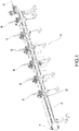
- an assembly station for Venetian blinds with complete support ladders according to the invention has been collectively indicated at 1.
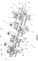
- the assembly station 1 for Venetian blinds with complete support ladders comprises three or more units 11, 12, 13, 14, 15, 16 for stacking slats on complete support ladders.
- Such stacking units 11, 12, 13, 14, 15, 16 are aligned with each other along an insertion axis X of the slats L inside the assembly station 1 and are slidably associated with a shared support structure 2 extending parallel to said insertion axis X between two opposite ends 1', 1" of the assembly station 1.
- the slats L enter the assembly station 1 at the first end 1' of such two opposite ends.
- the aforesaid stacking units 11, 12, 13, 14, 15, 16 jointly define a sliding lane 9 for the slat L along the insertion axis X inside the assembly station 1.
- each stacking unit is blockable in position along the shared support structure 2 and is slidably associated with such structure independently of the other units.
- the aforesaid shared support structure 2 consists of a bar extending parallel to the insertion axis X.
- the assembly station 1 comprises motorized means (not illustrated in the accompanying figures) for the movement of one or more of the aforesaid stacking units 11, 12, 13, 14, 15, 16 (preferably, independently of each other) along the aforesaid shared support structure 2 parallel to the insertion axis X.
- motorized means for the movement of one or more of the aforesaid stacking units 11, 12, 13, 14, 15, 16 (preferably, independently of each other) along the aforesaid shared support structure 2 parallel to the insertion axis X.
- the stacking units 11, 12, 13, 14, 15, 16 along such support structure 2, adapting the position thereof according to the length of the slats (i.e. the length of the blind to be produced) and/or the pitch required between one support ladder and another.
- the assembly station 1 may be equipped with means for moving the individual slat along the insertion axis X.
- means for moving the individual slat are made up of two pairs of opposing feeding rollers 3 and 4.
- the assembly station 1 may be suitable for handling complete support ladders of the type with single crosspieces or for handling complete support ladders with double crosspieces.
- each of the aforesaid stacking units 10 is equipped with divaricator means suitable to widen each pair of crosspieces in order to prepare them for the insertion of the slat.
- each of the stacking units 10 is manufactured according to one of the following European patents EP3026208B1 , EP2886781B1 , EP2677108B1 and EP2677107B1 in the name of the same applicant.
- the assembly station 1 according to the invention may be placed in line with a slat production machine or be placed off line so as not to slow down the faster slat production process.
- the assembly station 1 comprises a first end stop device 30 that engages the aforesaid sliding lane 9 to stop a slat L in movement along the insertion axis X.
- first end stop device 30 is slidably associated with the shared support structure 2. It is arranged downstream of the aforesaid three or more stacking units (11, 12, 13, 14, 15, 16) relative to the first end 1' of the assembly station 1.
- said first end stop device 30 is blockable in position along the shared support structure 2 independently of the stacking units.
- each of the stacking units 13, 14, 15, 16 arranged downstream of the first two stacking units 11, 12 relative to said first end 1' of the assembly station 1 is equipped with a second end stop device 20.
- Each second end stop device 20 is movable between an active position, wherein it engages the sliding lane 9 to stop the sliding of a slat (L), and a passive position, wherein it does not engage the sliding lane 9 allowing the sliding of a slat L through the respective stacking unit 13, 14, 15, 16.
- the stroke of one slat L along the sliding lane 9 may be stopped selectively:
- the stop function of the slat L is no longer carried out by a single stop/end stop device which must be disassembled and reassembled along the shared support structure, but by a series of end stop devices which may be activated and deactivated independently and which are slidably and stably associated with such shared support structure. This makes it possible to adjust the stop position of the slats quickly and easily, without requiring the assembly and disassembly of any device.
- each of the aforesaid second end stop devices 20 is associated with a stacking unit and therefore moves integrally therewith, they are not an obstacle to the normal operation of the assembly station 1.
- the aforesaid second end stop device 20 is placed in a front portion 10' of the respective stacking unit 13, 14, 15, 16 relative to the sliding direction X1 of the slats along the insertion axis X.
- the aforesaid second end stop device 20 faces the incoming slat and is not "hidden" by the stacking unit with which it is associated. Due to this, the second end stop device 20 may perform its function more quickly and easily.
- the second end stop device 20 extends mainly in a direction parallel to the insertion axis X, protruding from the respective stacking unit 13, 14, 15, 16 in a direction opposite to the sliding direction X1 of the slats along the insertion axis X. Due to such configuration, the second end stop device 20 is the first element that meets the incoming slat L when it is brought into the active position, i.e. when it engages the sliding lane 9.
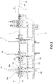
- the aforesaid second end stop device 20 is aligned with the aforesaid sliding lane 9 and, when in the passive position, is arranged completely below a sliding plane m of the slat defined by said sliding lane 9. In this way, the second end stop device 20 does not obstruct the movements of the slats in any way during the assembly of the Venetian blind.
- the second end stop device 20 When the second end stop device 20 is in the active position, it engages, with at least one portion thereof, the sliding lane 9, passing through the aforesaid sliding plane m of the slat. Due to the aforesaid alignment on the insertion axis, the stresses generated by the impact of the slat L on the second end stop device 20 are more easily absorbed by the same device.
- the aforesaid second end stop device 20 is structured to move between the active and passive positions in a direction orthogonal to the sliding plane m of the slat L.
- the movement of the second device 20 between the two operating positions occurs in a simple way by means of simple vertical movements (lifting and lowering).
- the second end stop device 20 comprises means 25 for moving between the active and passive positions.
- the aforesaid movement means 25 consist of a pneumatic piston.
- each stacking unit 11, 12, 13, 14, 15, 16 comprises:
- each insertion seat 10a also serves as the sliding seat for the slat L in a slat insertion step along the aforesaid insertion axis X within the assembly station 1.
- the aforesaid second end stop device 20 is placed in a front portion 10' of the respective stacking unit 13, 14, 15, 16 relative to the sliding direction X1 of the slats along the insertion axis X, upstream from the aforesaid device 10b to position a ladder transversely to the insertion axis X.
- the second end stop device 20 may never interfere with the aforesaid ladder positioning device or with the movement of the same ladder.
- each stacking unit 11, 12, 13, 14, 15, 16 may further comprise means 10c to guide the slat towards the aforesaid insertion seat 10a, arranged upstream of the aforesaid ladder positioning device 10b.
- the slat guiding means 10c comprise a guide chute, located at the inlet of the stacking unit 10.
- such guiding means may comprise a guide chamfer, obtained directly at the beginning of the insertion seat 10a.
- the aforesaid second end stop device 20 when in said passive position, is arranged completely below the aforesaid means 10c for guiding the slat. Only in the active position the aforesaid second end stop device 20 is partially arranged above the aforesaid means 10c for guiding the slat, in order to intercept the slat L and stop it.
- the second end stop device 20 consists of a plate with an L-shaped profile, having:
- the first portion 21 is movably associated with the structure of the respective stacking unit (13, 14, 15, 16) through the aforesaid means 25 for moving between the active and the passive position, preferably consisting of a pneumatic piston.
- the positioning of the stacking units 11, 12, 13, 14, 15, 16 and of the first end stop device 30 may be carried out manually. Preferably, however, such positioning is carried out automatically.
- the assembly station 1 comprises motorized means (not illustrated in the accompanying Figures) for the movement of one or more of the aforesaid stacking units 11, 12, 13, 14, 15, 16 (preferably, independently of each other) along the aforesaid shared support structure 2 parallel to the insertion axis X.
- motorized means for the movement of one or more of the aforesaid stacking units 11, 12, 13, 14, 15, 16 (preferably, independently of each other) along the aforesaid shared support structure 2 parallel to the insertion axis X.
- the assembly station 1 also comprises motorized means (not illustrated in the accompanying Figures) to move the first end stop device 30 along the shared support structure 2 parallel to the insertion axis X.
- the movement means of the stacking units may coincide with or be distinct from the movement means of the first end stop device 30.
- the aforesaid movement means are configured to allow independent movements of each stacking unit 11, 12, 13, 14, 15, 16 and of the first end stop device 30.
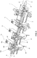
- FIG. 2 it comprises an electronic control unit 100 which is connected to the aforesaid motorized means (for moving the stacking unit and the first end stop device 30) and to the aforesaid means 25 for moving each second end stop device 20.
- This electronic control unit 100 is configured for:
- the electronic control unit 100 is configured to select with which end stop device (first end stop device 30 or one of the second end stop devices 20) and in which position along the axis X is the insertion stroke of the slats L to be stopped.
- the electronic control unit 100 is equipped with a user interface by means of which an operator may enter data relating to the Venetian blind to be assembled (in particular, slat length and positioning pitch of the ladders) and thus may define the operative requirements of the assembly station 1 according to which the electronic control unit 100 automatically controls the components of the assembly station 1.
- the assembly station 1 comprises means (not illustrated in the accompanying Figures) to detect the position along the shared support structure 2 (parallel to the insertion axis X) of each of the stacking units 11, 12, 13, 14, 15, 16 and of the first end stop device 30.
- detection means preferably consisting of encoders
- Such detection means are connected to the aforesaid electronic control unit 100.
- the invention allows many advantages already partly described to be obtained.
- the assembly station for Venetian blinds with complete support ladders allows the stop position of the slats to be adjusted more easily and quickly, without affecting the operation of the assembly station.
- the assembly station 1 according to the invention is also easier to manage than similar assembly stations of a known type.
- the assembly station 1 according to the invention is simple and economical to obtain.
Landscapes
- Engineering & Computer Science (AREA)
- Structural Engineering (AREA)
- Architecture (AREA)
- Civil Engineering (AREA)
- Blinds (AREA)
Priority Applications (2)
| Application Number | Priority Date | Filing Date | Title |
|---|---|---|---|
| PL19154093T PL3530865T3 (pl) | 2018-02-27 | 2019-01-29 | Stanowisko montażowe żaluzji o listewkach nastawnych z kompletnymi drabinkami nośnymi |
| SI201930066T SI3530865T1 (sl) | 2018-02-27 | 2019-01-29 | Montažna postaja za žaluzije s popolnimi opornimi lestvami |
Applications Claiming Priority (1)
| Application Number | Priority Date | Filing Date | Title |
|---|---|---|---|
| IT102018000003095A IT201800003095A1 (it) | 2018-02-27 | 2018-02-27 | Stazione di assemblaggio di tende a veneziana con scalette complete di sostegno |
Publications (2)
| Publication Number | Publication Date |
|---|---|
| EP3530865A1 EP3530865A1 (en) | 2019-08-28 |
| EP3530865B1 true EP3530865B1 (en) | 2021-03-10 |
Family
ID=62223093
Family Applications (1)
| Application Number | Title | Priority Date | Filing Date |
|---|---|---|---|
| EP19154093.9A Active EP3530865B1 (en) | 2018-02-27 | 2019-01-29 | Assembly station for venetian blinds with complete support ladders |
Country Status (6)
| Country | Link |
|---|---|
| EP (1) | EP3530865B1 (pl) |
| ES (1) | ES2875455T3 (pl) |
| IT (1) | IT201800003095A1 (pl) |
| PL (1) | PL3530865T3 (pl) |
| PT (1) | PT3530865T (pl) |
| SI (1) | SI3530865T1 (pl) |
Families Citing this family (1)
| Publication number | Priority date | Publication date | Assignee | Title |
|---|---|---|---|---|
| CN114251047B (zh) * | 2021-12-14 | 2022-11-04 | 黄海洲 | 一种全自动一体式百叶柔纱帘成型机 |
Family Cites Families (8)
| Publication number | Priority date | Publication date | Assignee | Title |
|---|---|---|---|---|
| US3766815A (en) * | 1971-01-08 | 1973-10-23 | Hunter Douglas International | Apparatus for forming strip |
| US5349730A (en) * | 1993-03-09 | 1994-09-27 | Hunter Douglas Inc. | Mehtod and apparatus for assembling blinds |
| EP0674092B1 (en) * | 1994-03-21 | 1997-10-08 | Hunter Douglas Industries B.V. | Venetian blind assembly machine ladder guide mechanism |
| CZ2009322A3 (cs) * | 2009-05-21 | 2010-12-01 | Zebr S.R.O. | Zpusob rozhrnování žaluziového žebrícku žaluziových lamel a rozhrnovací zarízení k jeho provádení |
| ITPD20120053A1 (it) | 2012-02-28 | 2013-08-29 | Dallan Spa | Unità di impilatura di lamelle su una scaletta di sostegno con traversi doppi per la produzione di tende veneziane |
| ITPD20120055A1 (it) | 2012-02-28 | 2013-08-29 | Dallan Spa | Unità di impilatura di lamelle su una scaletta di sostegno con traversi doppi per la produzione di tende veneziane e metodo di posizionamento di una scaletta |
| ITPD20130354A1 (it) | 2013-12-20 | 2015-06-21 | Dallan Spa | Unità di impilatura di lamelle su una scaletta di sostegno con traversi doppi per la produzione di tende veneziane e metodo di fissaggio di lamelle su una scaletta con traversi doppi |
| ES2651310T3 (es) * | 2014-11-25 | 2018-01-25 | Dallan S.P.A. | Unidad para apilar lamas en una escalera de soporte con vigas cruzadas dobles para la producción de persianas venecianas |
-
2018
- 2018-02-27 IT IT102018000003095A patent/IT201800003095A1/it unknown
-
2019
- 2019-01-29 PT PT191540939T patent/PT3530865T/pt unknown
- 2019-01-29 PL PL19154093T patent/PL3530865T3/pl unknown
- 2019-01-29 SI SI201930066T patent/SI3530865T1/sl unknown
- 2019-01-29 EP EP19154093.9A patent/EP3530865B1/en active Active
- 2019-01-29 ES ES19154093T patent/ES2875455T3/es active Active
Non-Patent Citations (1)
| Title |
|---|
| None * |
Also Published As
| Publication number | Publication date |
|---|---|
| PL3530865T3 (pl) | 2021-09-27 |
| EP3530865A1 (en) | 2019-08-28 |
| ES2875455T3 (es) | 2021-11-10 |
| PT3530865T (pt) | 2021-05-31 |
| SI3530865T1 (sl) | 2021-07-30 |
| IT201800003095A1 (it) | 2019-08-27 |
Similar Documents
| Publication | Publication Date | Title |
|---|---|---|
| US5333365A (en) | Apparatus for the manufacture of blinds | |
| EP2252760B1 (en) | Cellular window shade | |
| MXPA01004922A (es) | Persiana veneciana con inclinacion variable. | |
| EP3202563A1 (en) | Machine for assembling cardboard boxes, with a feeding device | |
| EP3530865B1 (en) | Assembly station for venetian blinds with complete support ladders | |
| EP3026208B1 (en) | Unit for stacking slats on a support ladder with double crossbeams for the production of venetian blinds | |
| US9121219B2 (en) | Roman blind | |
| EP2886781B1 (en) | Stacking unit of slats on a support ladder with double crossbeams for the production of venetian blinds and method of attaching slats to a ladder with double crossbeams | |
| AU678680B2 (en) | Venetian blind assembly machine ladder guide mechanism | |
| US8266784B2 (en) | Processing module positioning system for window blind slats | |
| US20110203744A1 (en) | Venetian Blind | |
| KR102113181B1 (ko) | 베네시안 블라인드의 가동장치 | |
| EP3561215B1 (en) | Stacking unit of slats on a support ladder for the production of venetian blinds and method of stacking slats on a support ladder | |
| EP3530864B1 (en) | Assembly station of venetian blinds with complete support ladders | |
| EP2850005B1 (en) | Device and method for the realisation of ventilated stabilizing coverings, made of plastic film, for palletized loads | |
| EP3379918A1 (en) | Screensystem and greenhouse | |
| US11304535B2 (en) | Machine and method for assembling a bedding foundation | |
| EP3013714B1 (en) | Roller conveyor | |
| EP3409874B1 (en) | Station for assembling venetian blinds | |
| EP2990583B1 (en) | Unit for stacking venetian blind slats on support structure and method of positioning a support structure in a unit for stacking slats | |
| KR102518305B1 (ko) | 슬라이딩 도어 연동장치 및 이를 적용한 슬라이딩 도어 | |
| CN220011471U (zh) | 一种飞达加长可调辅助结构 | |
| CN117508756A (zh) | 一种棉签盒包装设备 | |
| DE2501005A1 (de) | Hebevorrichtung fuer stapelgut, insbesondere platten | |
| CN105060162A (zh) | 升降机构 |
Legal Events
| Date | Code | Title | Description |
|---|---|---|---|
| PUAI | Public reference made under article 153(3) epc to a published international application that has entered the european phase |
Free format text: ORIGINAL CODE: 0009012 |
|
| STAA | Information on the status of an ep patent application or granted ep patent |
Free format text: STATUS: THE APPLICATION HAS BEEN PUBLISHED |
|
| AK | Designated contracting states |
Kind code of ref document: A1 Designated state(s): AL AT BE BG CH CY CZ DE DK EE ES FI FR GB GR HR HU IE IS IT LI LT LU LV MC MK MT NL NO PL PT RO RS SE SI SK SM TR |
|
| AX | Request for extension of the european patent |
Extension state: BA ME |
|
| STAA | Information on the status of an ep patent application or granted ep patent |
Free format text: STATUS: REQUEST FOR EXAMINATION WAS MADE |
|
| 17P | Request for examination filed |
Effective date: 20200218 |
|
| RBV | Designated contracting states (corrected) |
Designated state(s): AL AT BE BG CH CY CZ DE DK EE ES FI FR GB GR HR HU IE IS IT LI LT LU LV MC MK MT NL NO PL PT RO RS SE SI SK SM TR |
|
| GRAP | Despatch of communication of intention to grant a patent |
Free format text: ORIGINAL CODE: EPIDOSNIGR1 |
|
| STAA | Information on the status of an ep patent application or granted ep patent |
Free format text: STATUS: GRANT OF PATENT IS INTENDED |
|
| INTG | Intention to grant announced |
Effective date: 20201008 |
|
| GRAS | Grant fee paid |
Free format text: ORIGINAL CODE: EPIDOSNIGR3 |
|
| GRAA | (expected) grant |
Free format text: ORIGINAL CODE: 0009210 |
|
| STAA | Information on the status of an ep patent application or granted ep patent |
Free format text: STATUS: THE PATENT HAS BEEN GRANTED |
|
| AK | Designated contracting states |
Kind code of ref document: B1 Designated state(s): AL AT BE BG CH CY CZ DE DK EE ES FI FR GB GR HR HU IE IS IT LI LT LU LV MC MK MT NL NO PL PT RO RS SE SI SK SM TR |
|
| REG | Reference to a national code |
Ref country code: GB Ref legal event code: FG4D |
|
| REG | Reference to a national code |
Ref country code: CH Ref legal event code: EP Ref country code: AT Ref legal event code: REF Ref document number: 1369988 Country of ref document: AT Kind code of ref document: T Effective date: 20210315 |
|
| REG | Reference to a national code |
Ref country code: IE Ref legal event code: FG4D |
|
| REG | Reference to a national code |
Ref country code: DE Ref legal event code: R096 Ref document number: 602019002995 Country of ref document: DE |
|
| REG | Reference to a national code |
Ref country code: PT Ref legal event code: SC4A Ref document number: 3530865 Country of ref document: PT Date of ref document: 20210531 Kind code of ref document: T Free format text: AVAILABILITY OF NATIONAL TRANSLATION Effective date: 20210524 |
|
| REG | Reference to a national code |
Ref country code: LT Ref legal event code: MG9D |
|
| PG25 | Lapsed in a contracting state [announced via postgrant information from national office to epo] |
Ref country code: LT Free format text: LAPSE BECAUSE OF FAILURE TO SUBMIT A TRANSLATION OF THE DESCRIPTION OR TO PAY THE FEE WITHIN THE PRESCRIBED TIME-LIMIT Effective date: 20210310 Ref country code: NO Free format text: LAPSE BECAUSE OF FAILURE TO SUBMIT A TRANSLATION OF THE DESCRIPTION OR TO PAY THE FEE WITHIN THE PRESCRIBED TIME-LIMIT Effective date: 20210610 Ref country code: BG Free format text: LAPSE BECAUSE OF FAILURE TO SUBMIT A TRANSLATION OF THE DESCRIPTION OR TO PAY THE FEE WITHIN THE PRESCRIBED TIME-LIMIT Effective date: 20210610 Ref country code: GR Free format text: LAPSE BECAUSE OF FAILURE TO SUBMIT A TRANSLATION OF THE DESCRIPTION OR TO PAY THE FEE WITHIN THE PRESCRIBED TIME-LIMIT Effective date: 20210611 Ref country code: FI Free format text: LAPSE BECAUSE OF FAILURE TO SUBMIT A TRANSLATION OF THE DESCRIPTION OR TO PAY THE FEE WITHIN THE PRESCRIBED TIME-LIMIT Effective date: 20210310 Ref country code: HR Free format text: LAPSE BECAUSE OF FAILURE TO SUBMIT A TRANSLATION OF THE DESCRIPTION OR TO PAY THE FEE WITHIN THE PRESCRIBED TIME-LIMIT Effective date: 20210310 |
|
| REG | Reference to a national code |
Ref country code: NL Ref legal event code: MP Effective date: 20210310 |
|
| PG25 | Lapsed in a contracting state [announced via postgrant information from national office to epo] |
Ref country code: RS Free format text: LAPSE BECAUSE OF FAILURE TO SUBMIT A TRANSLATION OF THE DESCRIPTION OR TO PAY THE FEE WITHIN THE PRESCRIBED TIME-LIMIT Effective date: 20210310 Ref country code: LV Free format text: LAPSE BECAUSE OF FAILURE TO SUBMIT A TRANSLATION OF THE DESCRIPTION OR TO PAY THE FEE WITHIN THE PRESCRIBED TIME-LIMIT Effective date: 20210310 Ref country code: SE Free format text: LAPSE BECAUSE OF FAILURE TO SUBMIT A TRANSLATION OF THE DESCRIPTION OR TO PAY THE FEE WITHIN THE PRESCRIBED TIME-LIMIT Effective date: 20210310 |
|
| PG25 | Lapsed in a contracting state [announced via postgrant information from national office to epo] |
Ref country code: NL Free format text: LAPSE BECAUSE OF FAILURE TO SUBMIT A TRANSLATION OF THE DESCRIPTION OR TO PAY THE FEE WITHIN THE PRESCRIBED TIME-LIMIT Effective date: 20210310 |
|
| PG25 | Lapsed in a contracting state [announced via postgrant information from national office to epo] |
Ref country code: SM Free format text: LAPSE BECAUSE OF FAILURE TO SUBMIT A TRANSLATION OF THE DESCRIPTION OR TO PAY THE FEE WITHIN THE PRESCRIBED TIME-LIMIT Effective date: 20210310 Ref country code: EE Free format text: LAPSE BECAUSE OF FAILURE TO SUBMIT A TRANSLATION OF THE DESCRIPTION OR TO PAY THE FEE WITHIN THE PRESCRIBED TIME-LIMIT Effective date: 20210310 |
|
| REG | Reference to a national code |
Ref country code: ES Ref legal event code: FG2A Ref document number: 2875455 Country of ref document: ES Kind code of ref document: T3 Effective date: 20211110 |
|
| PG25 | Lapsed in a contracting state [announced via postgrant information from national office to epo] |
Ref country code: SK Free format text: LAPSE BECAUSE OF FAILURE TO SUBMIT A TRANSLATION OF THE DESCRIPTION OR TO PAY THE FEE WITHIN THE PRESCRIBED TIME-LIMIT Effective date: 20210310 Ref country code: RO Free format text: LAPSE BECAUSE OF FAILURE TO SUBMIT A TRANSLATION OF THE DESCRIPTION OR TO PAY THE FEE WITHIN THE PRESCRIBED TIME-LIMIT Effective date: 20210310 Ref country code: IS Free format text: LAPSE BECAUSE OF FAILURE TO SUBMIT A TRANSLATION OF THE DESCRIPTION OR TO PAY THE FEE WITHIN THE PRESCRIBED TIME-LIMIT Effective date: 20210710 |
|
| REG | Reference to a national code |
Ref country code: DE Ref legal event code: R097 Ref document number: 602019002995 Country of ref document: DE |
|
| PLBE | No opposition filed within time limit |
Free format text: ORIGINAL CODE: 0009261 |
|
| STAA | Information on the status of an ep patent application or granted ep patent |
Free format text: STATUS: NO OPPOSITION FILED WITHIN TIME LIMIT |
|
| PG25 | Lapsed in a contracting state [announced via postgrant information from national office to epo] |
Ref country code: AL Free format text: LAPSE BECAUSE OF FAILURE TO SUBMIT A TRANSLATION OF THE DESCRIPTION OR TO PAY THE FEE WITHIN THE PRESCRIBED TIME-LIMIT Effective date: 20210310 Ref country code: DK Free format text: LAPSE BECAUSE OF FAILURE TO SUBMIT A TRANSLATION OF THE DESCRIPTION OR TO PAY THE FEE WITHIN THE PRESCRIBED TIME-LIMIT Effective date: 20210310 |
|
| 26N | No opposition filed |
Effective date: 20211213 |
|
| PG25 | Lapsed in a contracting state [announced via postgrant information from national office to epo] |
Ref country code: IS Free format text: LAPSE BECAUSE OF FAILURE TO SUBMIT A TRANSLATION OF THE DESCRIPTION OR TO PAY THE FEE WITHIN THE PRESCRIBED TIME-LIMIT Effective date: 20210710 |
|
| PG25 | Lapsed in a contracting state [announced via postgrant information from national office to epo] |
Ref country code: MC Free format text: LAPSE BECAUSE OF FAILURE TO SUBMIT A TRANSLATION OF THE DESCRIPTION OR TO PAY THE FEE WITHIN THE PRESCRIBED TIME-LIMIT Effective date: 20210310 |
|
| REG | Reference to a national code |
Ref country code: BE Ref legal event code: MM Effective date: 20220131 |
|
| PG25 | Lapsed in a contracting state [announced via postgrant information from national office to epo] |
Ref country code: LU Free format text: LAPSE BECAUSE OF NON-PAYMENT OF DUE FEES Effective date: 20220129 |
|
| PG25 | Lapsed in a contracting state [announced via postgrant information from national office to epo] |
Ref country code: BE Free format text: LAPSE BECAUSE OF NON-PAYMENT OF DUE FEES Effective date: 20220131 |
|
| REG | Reference to a national code |
Ref country code: AT Ref legal event code: UEP Ref document number: 1369988 Country of ref document: AT Kind code of ref document: T Effective date: 20210310 |
|
| PG25 | Lapsed in a contracting state [announced via postgrant information from national office to epo] |
Ref country code: IE Free format text: LAPSE BECAUSE OF NON-PAYMENT OF DUE FEES Effective date: 20220129 |
|
| P01 | Opt-out of the competence of the unified patent court (upc) registered |
Effective date: 20230526 |
|
| GBPC | Gb: european patent ceased through non-payment of renewal fee |
Effective date: 20230129 |
|
| PG25 | Lapsed in a contracting state [announced via postgrant information from national office to epo] |
Ref country code: GB Free format text: LAPSE BECAUSE OF NON-PAYMENT OF DUE FEES Effective date: 20230129 |
|
| PGFP | Annual fee paid to national office [announced via postgrant information from national office to epo] |
Ref country code: PT Payment date: 20231221 Year of fee payment: 6 |
|
| PGFP | Annual fee paid to national office [announced via postgrant information from national office to epo] |
Ref country code: ES Payment date: 20240201 Year of fee payment: 6 |
|
| PG25 | Lapsed in a contracting state [announced via postgrant information from national office to epo] |
Ref country code: MK Free format text: LAPSE BECAUSE OF FAILURE TO SUBMIT A TRANSLATION OF THE DESCRIPTION OR TO PAY THE FEE WITHIN THE PRESCRIBED TIME-LIMIT Effective date: 20210310 Ref country code: CY Free format text: LAPSE BECAUSE OF FAILURE TO SUBMIT A TRANSLATION OF THE DESCRIPTION OR TO PAY THE FEE WITHIN THE PRESCRIBED TIME-LIMIT Effective date: 20210310 |
|
| PGFP | Annual fee paid to national office [announced via postgrant information from national office to epo] |
Ref country code: SI Payment date: 20240118 Year of fee payment: 6 |
|
| PG25 | Lapsed in a contracting state [announced via postgrant information from national office to epo] |
Ref country code: HU Free format text: LAPSE BECAUSE OF FAILURE TO SUBMIT A TRANSLATION OF THE DESCRIPTION OR TO PAY THE FEE WITHIN THE PRESCRIBED TIME-LIMIT; INVALID AB INITIO Effective date: 20190129 |
|
| PGFP | Annual fee paid to national office [announced via postgrant information from national office to epo] |
Ref country code: PL Payment date: 20240109 Year of fee payment: 6 Ref country code: FR Payment date: 20240124 Year of fee payment: 6 |
|
| PG25 | Lapsed in a contracting state [announced via postgrant information from national office to epo] |
Ref country code: MT Free format text: LAPSE BECAUSE OF FAILURE TO SUBMIT A TRANSLATION OF THE DESCRIPTION OR TO PAY THE FEE WITHIN THE PRESCRIBED TIME-LIMIT Effective date: 20210310 |
|
| PGFP | Annual fee paid to national office [announced via postgrant information from national office to epo] |
Ref country code: DE Payment date: 20250127 Year of fee payment: 7 |
|
| PGFP | Annual fee paid to national office [announced via postgrant information from national office to epo] |
Ref country code: CH Payment date: 20250201 Year of fee payment: 7 Ref country code: AT Payment date: 20250120 Year of fee payment: 7 |
|
| PGFP | Annual fee paid to national office [announced via postgrant information from national office to epo] |
Ref country code: IT Payment date: 20241114 Year of fee payment: 7 |
|
| PG25 | Lapsed in a contracting state [announced via postgrant information from national office to epo] |
Ref country code: PT Free format text: LAPSE BECAUSE OF NON-PAYMENT OF DUE FEES Effective date: 20250729 |
|
| PG25 | Lapsed in a contracting state [announced via postgrant information from national office to epo] |
Ref country code: FR Free format text: LAPSE BECAUSE OF NON-PAYMENT OF DUE FEES Effective date: 20250131 |
|
| PG25 | Lapsed in a contracting state [announced via postgrant information from national office to epo] |
Ref country code: TR Free format text: LAPSE BECAUSE OF FAILURE TO SUBMIT A TRANSLATION OF THE DESCRIPTION OR TO PAY THE FEE WITHIN THE PRESCRIBED TIME-LIMIT Effective date: 20210310 |
|
| PGFP | Annual fee paid to national office [announced via postgrant information from national office to epo] |
Ref country code: CZ Payment date: 20251212 Year of fee payment: 8 |
|
| REG | Reference to a national code |
Ref country code: SI Ref legal event code: KO00 Effective date: 20250130 |
|
| REG | Reference to a national code |
Ref country code: CH Ref legal event code: U11 Free format text: ST27 STATUS EVENT CODE: U-0-0-U10-U11 (AS PROVIDED BY THE NATIONAL OFFICE) Effective date: 20260201 |
|
| REG | Reference to a national code |
Ref country code: ES Ref legal event code: FD2A Effective date: 20260227 |