EP3530592A1 - Stacker crane - Google Patents
Stacker crane Download PDFInfo
- Publication number
- EP3530592A1 EP3530592A1 EP17863134.7A EP17863134A EP3530592A1 EP 3530592 A1 EP3530592 A1 EP 3530592A1 EP 17863134 A EP17863134 A EP 17863134A EP 3530592 A1 EP3530592 A1 EP 3530592A1
- Authority
- EP
- European Patent Office
- Prior art keywords
- mast
- traveling
- stacker crane
- masts
- carriage
- Prior art date
- Legal status (The legal status is an assumption and is not a legal conclusion. Google has not performed a legal analysis and makes no representation as to the accuracy of the status listed.)
- Granted
Links
Images


Classifications
-
- B—PERFORMING OPERATIONS; TRANSPORTING
- B66—HOISTING; LIFTING; HAULING
- B66F—HOISTING, LIFTING, HAULING OR PUSHING, NOT OTHERWISE PROVIDED FOR, e.g. DEVICES WHICH APPLY A LIFTING OR PUSHING FORCE DIRECTLY TO THE SURFACE OF A LOAD
- B66F9/00—Devices for lifting or lowering bulky or heavy goods for loading or unloading purposes
- B66F9/06—Devices for lifting or lowering bulky or heavy goods for loading or unloading purposes movable, with their loads, on wheels or the like, e.g. fork-lift trucks
- B66F9/07—Floor-to-roof stacking devices, e.g. "stacker cranes", "retrievers"
- B66F9/072—Travelling gear therefor
-
- B—PERFORMING OPERATIONS; TRANSPORTING
- B65—CONVEYING; PACKING; STORING; HANDLING THIN OR FILAMENTARY MATERIAL
- B65G—TRANSPORT OR STORAGE DEVICES, e.g. CONVEYORS FOR LOADING OR TIPPING, SHOP CONVEYOR SYSTEMS OR PNEUMATIC TUBE CONVEYORS
- B65G1/00—Storing articles, individually or in orderly arrangement, in warehouses or magazines
- B65G1/02—Storage devices
- B65G1/04—Storage devices mechanical
- B65G1/0407—Storage devices mechanical using stacker cranes
-
- B—PERFORMING OPERATIONS; TRANSPORTING
- B65—CONVEYING; PACKING; STORING; HANDLING THIN OR FILAMENTARY MATERIAL
- B65G—TRANSPORT OR STORAGE DEVICES, e.g. CONVEYORS FOR LOADING OR TIPPING, SHOP CONVEYOR SYSTEMS OR PNEUMATIC TUBE CONVEYORS
- B65G1/00—Storing articles, individually or in orderly arrangement, in warehouses or magazines
- B65G1/02—Storage devices
- B65G1/023—Arrangements of article supporting rollers on racks
-
- B—PERFORMING OPERATIONS; TRANSPORTING
- B65—CONVEYING; PACKING; STORING; HANDLING THIN OR FILAMENTARY MATERIAL
- B65G—TRANSPORT OR STORAGE DEVICES, e.g. CONVEYORS FOR LOADING OR TIPPING, SHOP CONVEYOR SYSTEMS OR PNEUMATIC TUBE CONVEYORS
- B65G1/00—Storing articles, individually or in orderly arrangement, in warehouses or magazines
- B65G1/02—Storage devices
- B65G1/04—Storage devices mechanical
-
- B—PERFORMING OPERATIONS; TRANSPORTING
- B66—HOISTING; LIFTING; HAULING
- B66F—HOISTING, LIFTING, HAULING OR PUSHING, NOT OTHERWISE PROVIDED FOR, e.g. DEVICES WHICH APPLY A LIFTING OR PUSHING FORCE DIRECTLY TO THE SURFACE OF A LOAD
- B66F9/00—Devices for lifting or lowering bulky or heavy goods for loading or unloading purposes
- B66F9/06—Devices for lifting or lowering bulky or heavy goods for loading or unloading purposes movable, with their loads, on wheels or the like, e.g. fork-lift trucks
- B66F9/07—Floor-to-roof stacking devices, e.g. "stacker cranes", "retrievers"
-
- H—ELECTRICITY
- H10—SEMICONDUCTOR DEVICES; ELECTRIC SOLID-STATE DEVICES NOT OTHERWISE PROVIDED FOR
- H10P—GENERIC PROCESSES OR APPARATUS FOR THE MANUFACTURE OR TREATMENT OF DEVICES COVERED BY CLASS H10
- H10P72/00—Handling or holding of wafers, substrates or devices during manufacture or treatment thereof
- H10P72/30—Handling or holding of wafers, substrates or devices during manufacture or treatment thereof for conveying, e.g. between different workstations
- H10P72/32—Handling or holding of wafers, substrates or devices during manufacture or treatment thereof for conveying, e.g. between different workstations between different workstations
- H10P72/3221—Overhead conveying
-
- H—ELECTRICITY
- H10—SEMICONDUCTOR DEVICES; ELECTRIC SOLID-STATE DEVICES NOT OTHERWISE PROVIDED FOR
- H10P—GENERIC PROCESSES OR APPARATUS FOR THE MANUFACTURE OR TREATMENT OF DEVICES COVERED BY CLASS H10
- H10P72/00—Handling or holding of wafers, substrates or devices during manufacture or treatment thereof
- H10P72/30—Handling or holding of wafers, substrates or devices during manufacture or treatment thereof for conveying, e.g. between different workstations
- H10P72/32—Handling or holding of wafers, substrates or devices during manufacture or treatment thereof for conveying, e.g. between different workstations between different workstations
- H10P72/3222—Loading to or unloading from a conveyor
Definitions
- the present invention relates to a stacker crane.
- a stacker crane for transferring an article is used in an automated storage and a facility such as an intrabay in which processing machine is arranged (One example is described in the following Patent Literature 1).
- the stacker crane includes, for example, a traveling carriage traveling along a track provided on a floor surface of a facility, a mast extending upward from the traveling carriage, an elevating platform moving along the mast, and a transfer device provided on the elevating platform.
- Such a stacker crane is capable of moving the entire stacker crane by a carriage drive unit of the traveling carriage. The longer the mast is, or the larger the acceleration of the traveling carriage is, the stress and moment applied to the connecting part between the mast and the traveling carriage become larger. As a result, the higher rigidity is required for the mast, and the weight of the mast becomes heavier.
- the stacker crane of Patent Literature 1 includes travelling carriages (vehicles) at the upper and lower positions.
- the mast is swingably attached to each of the upper and lower traveling carriages. Additionally, the mast is attached to one of the traveling carriages so as to freely shift in the vertical direction.
- the stress and moment applied to the connecting part between the mast and the traveling carriage can be reduced. As a result, the weight of the stacker crane of Patent Literature 1 decreases.
- Patent Literature 1 Japanese Patent No. 3591638
- the stacker crane of Patent Literature 1 enables to reduce the weight of the mast, however it requires two traveling carriages such as at least one upper and one lower traveling carriage.
- a track such as a rail is required for the lower traveling carriage traveling on the floor surface, it is necessary to lay a large number of rails on the floor surface in the facility, and an increase in cost is incurred.
- the position of the mast relative to the transfer destination of the article may be displaced.
- the position of the elevating platform is deviated from the transfer destination. As a result, it is difficult to transfer the article to a target position.
- a stacker crane includes a carriage drive unit, a traveling carriage which travels on a track provided on the ceiling side of the facility, a mast suspended from the traveling carriage, an elevating platform which is vertically movable and guided along the mast, a transfer unit for transferring an article to the elevating platform, a stopper for fixing the mast, and a switching unit for switching a state of the mast between a fixed state and a released state by the stopper.
- the switching unit releases the fixing of the stopper and then the lower part of each of the masts follows the upper part of each of the masts in the traveling direction of the traveling carriage.
- the stopper fixes the lower part of each of the masts.
- the masts may be provided on the both sides of the elevating platform in the traveling direction of the traveling carriage.
- the stacker crane may include a lower support base connected to the lower end of each of the masts.
- the stoppers may be provided on the lower support base. The stopper may move back and forth so as to come into contact with or separate from the floor surface.
- the stacker crane may be provided with a detector for detecting a deviation of an actual stop position of the lower part of each of the masts fixed by the stopper from a predetermined target stop position.
- the stacker crane may further include a calibrator for adjusting the displacement detected by the detector.
- the stacker crane may also be provided with a guide roller for guiding the traveling carriage along a rail formed on a floor surface of a part of the track at the lower part of each of the masts.
- the elevating platform may further include a mast guide moving up and down along the mast.
- the transfer unit transfers the article in the direction perpendicular and horizontal to the traveling direction of the traveling carriage.
- the rigidity of the mast in both vertical and horizontal directions to the traveling direction of the traveling carriage is preferably higher than that of the mast in the traveling direction of the traveling carriage.
- a suppressor may be provided to reduce and control the oscillation or vibration of the mast.
- the weight of the mast can be reduced.
- a guide rail need not be installed on the floor within the facility and the facility cost can be reduced.
- the stoppers fix the mast. That allows the stacker crane to transfer the article to a target position while the elevating platform and the transfer unit are stopped at the predetermined positions.
- the stacker crane may include a plurality of masts and stoppers.
- the stacker crane includes the masts on the front and rear sides of the elevating platform in the traveling direction of the traveling carriage, the lower support base connected to the lower end of each of the masts, and the stoppers on the lower support base.
- the stoppers of this embodiment can easily fix the plurality of masts at the lower part via the lower support base.
- the stoppers may further be configured to advance and retreat so as to contact with or separate from the floor surface.
- the switching unit can easily switch a state of the mast between a fixed state and a released state.
- the detector may be provided for detecting a deviation of the actual stop position of the lower part of each of the masts fixed by the stoppers from the predetermined target stop position.
- the detector can easily detect the deviation of the lower part of each of the masts from the target stop position.
- the calibrator may be provided for adjusting the deviation detected by the detector. This calibrator can adjust the deviation of the lower part of each of the masts, thus the stacker crane of this example enables the deviation of the actual transfer position from the target transfer position easily to be adjusted.
- guide rollers are provided at the lower part of each of the masts for guiding the traveling carriage to the guide rail formed on the floor surface of the section where the traveling carriage travels.
- the elevating platform may be provided with mast guides to move up and down along the mast.
- the mast guides allow the elevating platform to move up and down smoothly.
- the mast preferably has higher rigidity in the horizontal direction than in the traveling direction.
- Such mast can support a force generated in the horizontal direction and prevent the transfer direction of the article from deviating from the target position when the article is transferred.
- the stacker crane may further include a suppressor for suppressing the oscillation or vibration of the mast to prevent the vibration from being transmitted to the article.
- a direction is described by using a Cartesian XYZ coordinate system.
- a vertical direction is indicated as the Z direction
- a horizontal direction is indicated as the X direction and the Y direction.
- a direction indicated by an arrow is expressed as + direction (for example, the +X direction) and the opposite direction is expressed as the -X direction (for example, the -X direction).
- FIG. 1 is a diagram showing a transport system to which a stacker crane according to an embodiment of the present invention is applied.
- a transport system 1A is installed in a semiconductor device fabrication plant and applied to a system which transports a FOUP (Front Opening Unified Pod) containing semiconductor wafers used for semiconductor device manufacture or an article 2 such as a reticle pod containing processing components such as a reticle.
- FOUP Front Opening Unified Pod
- the article 2 is described as a FOUP, but not limited to this.
- the transport system 1A is applicable to facilities except for the semiconductor field, and the article 2 may be a variety of articles handled in the facility where the transport system 1A is installed.
- the transport system 1A includes a stacker crane 3 and a track 4.
- the track 4 is a traveling rail and is suspended from a ceiling 5 of the facility with a plurality of rail support members 5a.
- the stacker crane 3 travels along the track 4 and transfers the article 2 to the transfer destination.
- the transfer destination or transfer origin of the article 2 includes, but is not limited to, a load port 32a of a processing machine 32 (shown in FIG. 4 ), a storage shelf 31 arranged in a stocker (automated storage) or on the processing machine (shown later in FIG. 4 ), or a buffer.
- the processing machine includes, for example, an exposure machine, a coater developer, a film forming device, or an etching device and applies various kinds of processing to the semiconductor wafer housed in the article 2.
- the stocker stores the article 2 transported by the transport system 1A.
- the buffer includes a side track buffer (STB) or an under track buffer (UTB) which are installed near the processing machine.
- An overhead traveling vehicle of the transport system 1A (not shown) temporarily stores the article 2 in the buffer.
- the overhead traveling vehicle includes, for example, an OHT (Overhead Hoist Transport) or an OHV (Overhead Hoist Vehicle).
- the stacker crane 3 includes a traveling carriage 11, mast 12, an elevating platform 13, a transfer unit 14 and stoppers 15.
- the traveling carriage 11 travels along the track 4.
- the traveling direction of the traveling carriage 11 is the direction substantially parallel to the track 4 (the X direction in FIG. 1 ).
- the traveling carriage 11 includes, for example, a carriage drive unit 11a such as an electric motor, driving wheels 11b, driven wheels 11c, a decelerator (not shown) and an encoder (not shown).
- the driving wheels 11b are attached so as to be pressed against an inside upper surface of the track 4 by an elastic member (not shown) such as a spring and connected to the output shaft of the electric motor (carriage drive unit 11a) through the decelerator.
- the rotation of the output shaft of the electric motor is transmitted through the decelerator to the driving wheels 11b, and then the traveling carriage 11 travels by the rotation of the driving wheels 11b.
- a caster is attached to each driven wheel 11c so as to be rotatable around the caster axis in the vertical direction (the Z direction) and also be in contact with the inner bottom surface of the track 4.
- the encoder detects the rotation frequency of the output shaft of the electric motor and outputs the detection results to a controller (not shown).
- the controller controls the rotation frequency of the electric motor based on the results of the encoder and determines the speed and the stop position of the traveling carriage 11.
- the stop position of the traveling carriage 11 may be set by detecting an index plate installed in advance along the track 4.
- a linear motor may be used as the carriage drive unit 11a.
- the stacker crane 3 includes a rotary shaft 16 provided below the traveling carriage 11 and an upper support base 17 attached to the lower part of the rotary shaft 16.
- the masts 12 are attached to the upper support base 17 and suspended from the traveling carriage 11.
- the masts 12 are provided on both sides (a +X direction ⁇ a plus X-direction>, a -X direction ⁇ a minus X-direction>) of the traveling direction of the traveling carriage 11 (the X direction).
- the masts 12 may be attached to the upper support base 17, for example, with a fastening member such as a bolt and nut or by welding.
- the masts 12 are connected to a lower support base 20 at their lower ends.
- the lower support base 20 is connected to a + X-side mast 12 and - X-side mast 12 so that the distance between each of the masts at the lower support base 20 is equal to the distance between each of the masts at the upper support base 17.
- the lower support base 20 has, for example, a plate shape.
- the front and rear masts 12 are connected to the front and rear parts of the elevating platform 13 in the traveling direction of the traveling carriage.
- the elevating platform 13 will be described later in detail.
- the lower support base 20 having stoppers 15 which are configured to move back and forth so as to contact with or separate from the floor surface 6. The stoppers 15 will be described later in detail.
- the traveling carriage 11 accelerates in the traveling direction (for example, when the traveling carriage starts to travel from a stop state), the lower part of each of the masts 12 cannot follow the lower part of the traveling carriage 11 due to an inertia force, which causes a delay.
- the delay of the lower part of each of the masts 12 can be solved by the following method. For example, the carriage drive unit 11a temporarily decelerates the traveling carriage 11 or repeats to decelerate the traveling carriage 11 several times during acceleration or traveling.
- the carriage drive unit 11a can solve this problem by temporarily increasing the acceleration of the traveling carriage 11 or repeating such an increase in the acceleration over a plurality of times before or during slowing down to stop the traveling carriage 11.
- the stacker crane 3 includes a suppressor 21 for reducing the oscillation or vibration of the mast 12.
- FIG. 2 is a diagram showing an example of the suppressor 21.
- the suppressor 21 such as an air damper or an oil damper, applies a force to the mast in the direction (indicated by the arrow F) opposite to the movement of the mast 12 (indicated by the arrow D).
- the suppressor 21 includes, but is not limited to, an elastic member such as a coil spring or a mechanism such as an actuator for imparting a force to the mast 12.
- the elevating platform 13 moves up and down along the masts 12.
- the elevating platform 13 is placed between the +X side mast 12 and the -X side mast 12.
- the elevating platform 13 is suspended from the upper support base 17 with hoist cables (not shown) such as wires.
- the upper support base 17 is provided with an elevating drive unit 22 for winding up and down the hoist cables.
- the elevating drive unit 22 winds the hoist cables down and then the elevating platform 13 is guided to descend along the masts 12.
- the elevating drive unit 22 winds the hoist cable up and then the elevating platform 13 is guided to ascend along the masts 12.
- the transfer unit 14 is provided on the elevating platform 13.
- FIG. 3 shows an example of the masts 12, the mast guides 28, and the mast guides 29.
- FIG. 3A is a diagram in which the mast guide 28 and a pair of the mast guides 29 are applied to the masts 12 having square cross section.
- FIG. 3B is a diagram in which the mast guide 28 and a pair of the mast guides 29 are applied to the masts 12a having rectangle cross section to increase the rigidity in the transfer direction.
- the transfer unit 14 includes an arm 25 and a holder 26.
- the arm 25 includes an arm 25a and an arm 25b that are linked to each other with a joint 25c.
- the arm 25 expands and contracts in the horizontal direction which is the Y direction by folding the arm 25a and the arm 25b at the joint 25c.
- the arm 25 is connected to the elevating platform 13 at the proximal end and to the holder 26 at the distal end.
- the holder 26 has a plurality of (for example, three) pins 27 (for example, kinematic pins).
- the pins 27 respectively enter into a plurality of radial grooves formed on the bottom surface of the article 2. In this way, the pins 27 determine an accurate position of the article 2 on the holder 26.
- the transfer unit 14 extends the arm 25 towards the direction of the transfer origin and places the holder 26 under the bottom of the article 2 and then receives the article 2 from the transfer origin.
- the elevating platform 13 moves up, and then the transfer unit 14 scoops up the article 2 with the holder 26.
- the transfer unit 14 contracts the arm 25 while holding the article 2 on the holder 26 and then places the holder 26 on the elevating platform 13.
- the following describes how the transfer unit 14 transfers the article 2 to the transfer destination.
- the transfer unit 14 determines a position toward the transfer destination and extends the arm 25 and places the article 2 on the holder 26 above the transfer destination.
- the elevating platform 13 moves down, and then the transfer unit 14 transfers the article 2 from the holder 26 to the transfer destination.
- the transfer unit 14 shown in FIGS. 3A and 3B is one example and may have other structures.
- the transfer unit may hold the article 2 by firmly gripping a flange which is placed on the upper part of the article 2 or by holding the sides of the article 2.
- the transfer unit 14 may include, but is not limited to the arm 25.
- an articulated robotics arm may be used.
- a direction which the article 2 moves to when the transfer unit 14 transfers the article 2 is hereinafter referred to as a transfer direction accordingly.
- the expression "transfer direction” means a direction that the arm 25 extends and contracts to/from (the Y direction) and also a direction perpendicular and horizontal to the traveling direction of the traveling carriage 11 (the X direction).
- the elevating platform 13 incudes the mast guides 28 and the mast guides 29 for guiding the elevating platform 13 along the masts 12.
- the elevating platform 13 includes the mast guides 28 on its upper surface.
- Each of the mast guides 28 guides the +X side mast 12 and the -X side mast 12 in the traveling direction of the traveling carriage.
- the mast guides 28 regulate the moving path of the elevating platform 13 and the masts 12 in the X direction.
- the mast guides 28 regulate each position of the masts 12 on the +X side and the -X side with respect to the elevating platform 13.
- the mast guides 28 then determine the relative position of each of the masts 12 on the +X and - X sides in the X direction.
- the mast guides 29 are arranged so as to pinch each of the masts 12 on the +Y and -Y sides from the perpendicular direction and the horizontal direction (the transfer direction) to the traveling direction of the traveling carriage 11.
- the mast guide enables elevating platform 13 smoothly to move up and down. This allows the mast guide 28 to prevent interference between the mast 12 and the elevating platform 13.
- the mast guides 29 also prevent the elevating platform 13 from shifting to the transfer direction from the positions of the masts 12 and detaching from the moving path along each of the masts 12.
- the mast guides 28 may preferably pinch each of the +X side mast 12 and the -X side mast 12 from both sides.
- the mast guides 28 and the mast guides 29 prevent the elevating platform 13 from deviating from the moving path along each of the masts 12 as the mast guide 28 and a pair of the mast guides 29 surround each of the masts 12.
- a mast 12a in FIG. 3B and the mast 12 in FIG. 3A have different shape.
- the mast 12a has a higher rigidity in the direction perpendicular to the traveling direction of the traveling carriage 11 and the horizontal direction (the transfer direction, the Y direction) than in the traveling direction of the traveling carriage 11 (the X direction).
- the rigidity in the transfer direction is the rigidity to a bending moment around an axis parallel to the X direction.
- the rigidity in the traveling direction is the rigidity to the bending moment around an axis parallel to the Y direction.
- the dimension of the mast 12 in the Y direction is longer than that in the X direction, and the rigidity in the transfer direction is higher than that in the traveling direction.
- the holder 26 holds the article 2 and the arm 25 is extended, and then the transfer unit 14 receives a moment around an axis parallel to the X direction.
- the moment is transmitted to the mast 12 via the elevating platform 13.
- the mast 12a in the embodiment has the higher rigidity in the transfer direction than in the traveling direction, the weight of the mast 12a can be lightened by reducing the rigidity in the traveling direction, and the rigidity in the transfer direction enables the mast 12a to withstand the bending moment generated at the time of transferring the article.
- the weight of the stacker crane 3 supported by the ceiling is larger than the weight supported by the floor 6, when the traveling carriage 11 travels.
- the stacker crane 3 is not in contact with the floor 6 (in a state of being lifted from the floor 6) when the traveling carriage 11 travels.
- the total weight of the stacker crane 3 is supported by the track 4 and the weight supported by the floor surface 6 is approximately zero.
- the carriage drive unit 11 disposed at the upper side of the upper support unit including the upper support base 17 (for example, the carriage drive unit 11a) mainly supplies a driving force for the traveling carriage 11 to travel.
- the lower support unit including the lower support base 20 is not provided with the carriage drive unit for providing the driving force, the lower support base 20 moves by following the upper support base 17.
- the stoppers 15 fix the masts 12 to a stationary object.
- the stationary object includes, for example, the floor surface 6, the storage shelf 31 (such as the stocker or the buffer) or the processing machine 32.
- the stoppers 15 fix the masts to the floor 6, and then the transfer unit 14 transfers the article.
- the stoppers 15 include anchors on the lower support base 20 at the both sides of the traveling direction (the X direction).
- the stoppers 15 are capable of advancing or retreating (ascending or descending) above the floor surface 6.
- the stacker crane 3 also includes the switching unit 35 for switching the state of the mast between a fixed state and a released state.
- the switching unit 35 is attached on the lower support base 20, for example.
- the switching unit 35 is capable of switching between the fixed state and the released state by moving forward or backward the stoppers 15 by the stopper driver.
- the stoppers 15 may fix the masts 12 when parking the traveling carriage 11.
- the switching unit 35 controls the stoppers 15 to release the fixation of the stoppers and enables the lower part of each of the masts to follow the upper part of each of the masts 12 in the travelling direction.
- the switching unit 35 can control the stoppers 15 to fix the masts 12 (lower part of each of the masts 12) after the lower part of each of the masts 12 stops following the upper part of each of the masts 12 (after a predetermined time has passed from the stop of the traveling carriage 11) or immediately after the traveling carriage 11 stops.
- the stoppers 15 fix the masts 12 (lower support base 20) and then the relative position between the transfer destination and the elevating platform 13 is determined.
- the fixing of the masts 12 by the stoppers 15 is the preparation for position adjustment with respect to the transfer destination of the article 2, which will be explained later.
- the switching unit 35 enables the stoppers 15 to advance to the floor 6 and contact with the floor surface 6 to fix the lower support base 20 to the floor surface 6.
- the masts 12 are fixed to the floor 6 together with the lower support base 20 by the stoppers 15 as the lower end of each of the masts 12 is connected to the lower support base 20.
- the lower part of each of the masts 12 and the lower support base 20 are fixed to the stationary object (such as the floor surface 6).
- FIG. 4 shows one example of a transfer operation of the article 2
- FIG. 4A shows a state in which the article is in the process of being transferred to the load port
- FIG. 4B shows a diagram in which the article has reached the load port.
- the transport system 1A of this embodiment includes a storage shelf 31 for storing the article 2.
- the storage shelves 31 are aligned, for example, in the X direction with respect to the processing machine 32.
- the storage shelf 31 has a plurality of shelf plates 31a arranged in the vertical direction.
- the transfer unit 14 of the stacker crane 3 can receive and deliver the article 2 from/to each of the plurality of the shelf plates 31a.
- the switching unit 35 moves the stoppers 15 downward to contact with the floor surface 6 and fix the lower support base 20 and the lower part of each of the masts 12 to the floor 6, and the transfer unit 14 transfers the article 2 to the shelf plate 31a (in the fixed state).
- the switching unit 35 causes the stoppers 15 to fix the lower support base 20 and the lower part of each of the masts 12 to the floor 6, the transfer unit 14 receives the article 2 from the shelf plate 31a (in the fixed state).
- the transport system 1A may not include the storage shelf 31, and transfer the article 2 to some storage place other than the storage shelf 31. After the article 2 has been transferred completely, the switching unit 35 moves the stoppers 15 upward and away from the floor surface 6, and enables the traveling carriage 11 to travel freely (in the released state).
- the transfer unit 14 may transfer the article 2 from/to the load port 32a of the processing machine 32 other than from/to the storage shelf 31.
- the transfer unit 14 receives the article 2 from the storage shelf 31 and transfers the article 2 to the load port 32a.
- the transfer unit 14 also receives the article 2 from the load port 32a and transfers the article 2 to the storage shelf 31.
- the switching unit 35 moves the stoppers 15 downward to contact with the floor surface 6 and fix the lower support base 20 and the lower part of each of the masts 12 to the floor surface 6 in the same way as described above, and the transfer unit 14 transfers the article 2 from/to the load port 32a.
- the transfer unit 14 may transfer the article 2 from/to the stocker (automated storage) or the buffer (each of them not shown) as is the case with the load port 32a.
- the lower support base 20 and the lower part of each of the masts 12 are fixed to the floor surface 6 in a manner similar to that described above, and then the transfer unit 14 transfers the article 2 from/to the stocker.
- FIG. 5 shows one example of the stoppers 15 and a detector 37
- FIG. 5A is a diagram viewed from the X direction
- FIG. 5B is a diagram viewed in the Y direction
- FIG. 5C is a diagram viewed from the Z direction and showing a detection operation.
- the stoppers 15 as shown in FIGS. 5A and 5B have outriggers 36 for elevating and lowering from/to a position of the lower support base 20 by the switching unit 35.
- the outriggers 36 are brought into contact with the floor surface 6 to restrict the movement of the lower support base 20 in the horizontal direction and are movably attached to the lower support base 20.
- the switching unit 35 advances and retreats the outriggers 36 from/to the floor surface 6.
- the switching unit 35 is, for example, controlled by a controller of the stacker crane 3 (not shown). This controller manages to advance and retreat the outriggers 36 at the timing when the controller specifies. Note that, the structure of the stoppers 15 is not limited to the structure shown in FIG. 5 and other structures may be adopted.
- the stacker crane 3 may include the detector 37 as shown in FIGS. 5A to 5C .
- a distance sensor may be used as an example of the detector 37.
- the distance sensor is attached to the undersurface and also in a substantially center part of the lower support base 20 in the traveling direction via a stay 37a, but the detector 37 can be attached to any position.
- a mirror reflector 38 is placed at a position below the transfer destination of the article 2. The mirror reflector 38 is disposed on a side surface of the processing machine 32 (refer to FIG. 4 ) and also at a position below the load port 32a.
- a light-emitting element of the detector 37 emits the light to be detected such as laser light to the mirror reflector 38, the mirror reflector 38 reflects the light to be detected to the detector 37, and then a light-receiving element of the detector 37 detects the reflected light.
- a distance calculation section of the detector 37 measures a distance between the detector 37 (lower support base 20) and the mirror reflector 38. The measured distance is compared with the target distance recorded in a memory of the controller (not shown) of the stacker crane 3 and then the deviation amount in the Y direction is calculated.
- a calibrator 39 adjusts the position deviating from the target position by the distance calculated by the detector 37 or the controller of the stacker crane 3. The example of the transfer unit 14 used by the calibrator 39 is explained below.
- the stoppers 15 fix the lower support base 20 and the lower part of each of the masts 12 after the traveling carriage 11 stops at the target position.
- Such operation causes the lower support base 20 and the lower part of each of the masts 12 to deviate from the target stop position.
- the deviation amount of the traveling direction (the X direction deviation) is caused by the lower part of each of the masts 12 and the lower support base 20.
- the deviation amount can be reduced by using a drive source, which controls the acceleration and deceleration of the traveling carriage 11 during traveling, when the traveling carriage slows down to stop.
- the deviation amount of the transfer direction (the Y direction deviation) cannot be reduced because of the lack of adjustment by such a drive source.
- the Y direction deviation is expected to be generated as the masts 12 are swinging in the transfer direction. This allows that the deviation amount from the target stop position is likely to be larger in the transfer direction (the Y direction) than in the traveling direction (the X direction).
- the detector 37 detects a deviation in the transfer direction, and the detected deviation is adjusted by the calibrator 39. This allows the article to be transferred to the accurate position.
- the calibrator 39 using the transfer unit 14 is explained as an example.
- the transfer unit 14 extends the arm 25 up to the predetermined distance (the stroke length) (shown in FIG. 3 ).
- the detector 37 detects the deviation amount and sends the detected deviation amount to a controller of the transfer unit 14.
- the controller of the transfer unit 14 adjusts the stroke length according to the detected deviation amount. In this way, the calibrator 39 using the transfer unit 14 allows the article 2 to be accurately transferred to the transfer destination (for example, the storage shelf 31 in FIG. 4A ).
- the detector 37 may measure not only the deviation amount in the transfer direction but also the deviation amount in the traveling direction.
- the detector 37 emits the light to be detected toward the mirror reflector 38 provided in the traveling direction and detects the light reflected by the mirror reflector 38.
- the deviation amount in the traveling direction is calculated based on the information derived from the detected data.
- the detector 37 for measuring the deviation amount in this example is not limited to the distance sensor, but includes an image sensor mounted on the lower support base 20. A mark indicating the position of the processing machine 31 may be provided on the floor 6.
- the detector 37 measures the deviation in either one or both of the traveling and transfer direction to the target position by the image data captured by the image sensor.
- a transfer unit 14 is adopted as the calibrator 39, but it is not limited to, and the calibrator 39 may be configured with a unit that is mounted on the lower support base 20 and moves the transfer unit 14 in both the X and Y directions. Such a unit may also be configured to have only one movement direction, which is in either the X or Y direction. The combination of the two units enables the transfer unit 14 to move in both directions.
- FIG. 6 shows one example where guide rollers 42 are applied to the stacker crane
- FIG. 6A is a diagram viewed in the Z direction
- FIG. 6B is a diagram viewed in the Y direction.
- a plurality of guide rollers 42 are provided on the undersurface of the lower support base 20.
- Four guide rollers 42 are rotatable.
- the guide rollers 42 are held to one bracket 42a in pairs.
- the two brackets 42a are attached to the lower support base 20.
- Each guide roller 42 is rotatable around an axis in the vertical direction (the Z direction) and is placed at a substantially same height as the other guide roller 42 and also at an interval so as to allow to interpose a guide rail 41 (mentioned later.)
- the arrangement and the number of guide rollers 42 in the preferred embodiment are just one example and are not limited or restricted.
- FIG. 7 shows one example using the guide rail 41
- FIG. 7A is a diagram illustrating the travel state of the stacker crane 3
- FIG. 7B shows a diagram viewed from the X direction
- FIG. 7C shows a diagram viewed in the Y direction.
- the track 4 may include zones 4a and 4b.
- the zone 4a is curved and the zone 4b is linear.
- the guide rail 41 is installed along the curved zone 4a on the floor 6 but not along the linear zone 4b on the floor 6. In this way, the guide rail 41 may be installed along a certain zone on the floor 6 under the track 4.
- the lower support base 20 includes the guide rollers 42 which are guided by the guide rail 41.
- the guide rollers 42 are disposed to pinch the guide rail 41 in the transfer direction (the Y direction).
- Each guide roller 42 rotates in contact with the guide rail 41.
- a friction force between the guide rollers 42 and the guide rail 41 is, for example, set to be as small as it can be ignored against the friction force which can support the weight of the stacker crane 3, and the fact remains that a substantial amount of the total weight of the stacker crane 3 is still supported by the track 4.
- the centrifugal force is applied to the masts 12 in outward direction of the curve, which is perpendicular and horizontal to the traveling direction while the stacker crane 3 travels along the curve zone 4a.
- Such centrifugal force acts on the masts 12 as the bending moment in the transfer direction (perpendicular direction to the traveling direction and also horizontal direction).
- the guide rollers 42 guide the stacker crane 3 along the guide rail 41. At least a part of such centrifugal force acting on the guide rail 41 is received via the guide rollers 42. As a result, the moment acting on the masts 12 can be reduced.
- the weight of the stacker crane 3 becomes lighter as the rigidity required for the masts 12 or the connector between the masts 12 and the upper support base decreases.
- the linear zone 4b does not have the guide rail 41. Since the stacker crane 3 does not come into contact with the floor 6, the stacker crane 3 is fully supported by the track 4. The stacker crane 3 may not come into contact with the floor 6 in all zones of the track 4 or a part of zones of the track 4 (zone 4b).
- the guide rail 41 may also be installed in the linear zone 4b as shown in FIGS. 7B and 7C .
- FIG. 7 illustrates a structure where the guide rollers 42 guide the stacker crane 3 by rolling along the guide rail 41 which is installed on the floor 6, but is not limited to this structure.
- a guide member such as the guide rail 41 may be, for example, suspended from the ceiling 5 or provided on a part of the processing machine installed on the floor 6, as well as being installed on the floor 6.
- FIG. 8 shows one example of the transport system 1B using the stacker crane 3A according to another embodiment.
- FIG. 8A is a diagram viewed in the Y direction
- FIG. 8B is a diagram viewed from the X direction.
- the same reference signs are given to the components similar to that in the embodiment which is previously described. The explanation for the signs is omitted or simplified. Additionally, the switching unit 35 shown in FIG. 1 is not shown in FIG. 8 .
- the masts 12 and the upper support base 17 are connected by connectors 18.
- Each of the connectors 18 is, for example, hinged and has an axis 18a (refer to FIG. 8B ) in the perpendicular direction to the travel direction of the traveling carriage 11 (the X direction) and also in the horizontal direction (the Y direction).
- the connector 18 does not substantially transmit the moment around the axis 18a except for friction.
- the traveling carriage 11 supports the masts 12 with the connectors 18, which are configured to be rotatable (freely rotatable) around the axes 18a.
- the connectors 18 receive a moment around the axes 18a in two directions (the X direction, the Z direction) perpendicular to the axes 18a.
- the mechanism of the connectors 18 prevents the masts 12, which are arranged in the mast longitudinal direction and the vertical direction (the Z direction), from inclining to the lateral side (the -Y direction or the +Y direction) of the track 4 and from being twisted around the vertical direction (the Z direction) when the traveling carriage 11 travels.
- the connector 18 is described as a hinge in the embodiment, but it is not limited to, which includes an universal joint having a mechanism for rotatating around a plurality of axes (for example, the X direction, the Y direction).
- each of the masts 12 and the lower support base 20 are connected by connectors 19.
- Each of the connectors 19 is, for example, hinges and has an axis 19a (refer to FIG. 8B ) in the perpendicular direction to the traveling direction of the traveling carriage 11 (the X direction) and also the horizontal direction (the Y direction).
- the connector 19 does not substantially transmit the moment around the axis 19a except for the influence of friction.
- the connectors 19 connect the lower support base 20 and the masts 12 so as to support the lower support base 20 and the masts 12 rotatable (freely rotatable) around the axes 19a.
- the connector 19 receives the moment around two directions perpendicular to the axes 19a (the X direction, the Z direction), which is similar to the connector 18.
- the connector 19 prevents the mast 12 from being twisted by the lower support base 20 around the vertical direction (the Z direction).
- the connector 19 is described as hinge in the embodiment, but it is not limited to, which includes an universal joint having a mechanism for rotatating around a plurality of axes (for example, the X direction, the Y direction).
- the stacker crane 3A shown in FIG. 8 when the traveling carriage 11 accelerates or decelerates, the masts 12 are rotated and inclined by an inertia force on the lower support base 20 side. However, as the lower support base 20 is rotatable around the connector 19 of the mast 12, the stacker crane 3A maintains the substantially horizontal state even in a state where the masts 12 are inclined.
- a rectangular shape is formed by + X-side mast 12, - X-side mast 12, and upper and lower support base 17, 20. This shape changes from rectangular to parallelogram upon the acceleration and deceleration of the traveling carriage as the lower support base 20 moves in a time delay and moves ahead of a position below the upper support base 17. However, the lower support base 20 can maintain the substantially horizontal state at the time of acceleration and deceleration.
- the elevating platform 13 is, as shown in FIG. 8A , formed by connecting side and bottom plates via hinges 13a. Such hinges 13a rotatably connect the side and bottom plates of the elevating platform.
- the side plates enable the bottom plate of the elevating platform 13 to be horizontal by rotating along with the masts 12 when the masts 12 swing.
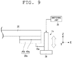
- FIG. 9 is a diagram showing calibrators 39a according to another embodiment.
- the transfer unit 14 is adopted as the calibrator 39, however the calibrators 39a shown in FIG. 9 may be used instead of the calibrator 39.
- the calibrators 39a are, as shown in FIG. 9 , provided on the undersurface of the lower support base 20 and also on the both sides of the traveling direction (the X direction).
- the calibrators 39a include a X axis slider 40a that can move from the undersurface of the lower support base 20 to the X direction and a Y axis slider 40b that can move from the undersurface of the X axis slider 40a to the Y direction.
- the stopper 15 includes a support member 15a for supporting, advancing, and retreating the outrigger 36.
- the Y axis slider 40b and the stopper 15 are connected by the support member 15a.
- the X axis slider 40a moves to the X direction by an X axis drive unit (not shown).
- the Y axis slider 40b moves to the Y direction by a Y axis drive unit(not shown).
- the calibrator 39a drives the X axis drive unit (not shown) and the Y axis drive unit (not shown) according to the deviation amount of the X direction (traveling direction) and the Y direction (transfer direction) detected by the detector 37 (refer to FIG. 5 ) to move the X axis slider 40a and the Y axis slider 40b, so that the relative position of the X direction (traveling direction) and the Y direction (transfer direction) toward the outrigger 36 can be adjusted via the support member 15a.
- the transfer unit 14 (refer to FIG. 1 ) can be placed at the appropriate position by this adjustment to accurately transfer the article 2 to the transfer destination.
- the structure shown in FIG. 9 is an example of an optional mechanism used by the stoppers 36 movable to the X direction (traveling direction) and the Y direction (transfer direction).
- the weight of the mast 12 can be lightened as the mast 12 is suspended from the traveling carriage 11.
- Facility costs can also be reduced as a number of guide rails 41 are not required on the floor 6 within the facility.
- the stoppers 15 fix the lower part of each of the masts 12 to the stationary object (the floor 6) while the article 2 is transferred. This enables the elevating platform 13 and the transfer unit 14 to be positioned accurately. Thus, the transfer unit 14 can transfer the article 2 to the target position.
- Overhead hoist vehicles set on the transport systems 1A, 1B may use at least a part of the track 4 as a rail.
- the track 4 is provided on the ceiling 5 of the facility via the rail support members 5a.
- the track 4 may be provided directly on the ceiling 5 or, for example, on a frame (beam) formed near the ceiling 5.
- the stoppers 15 come into contact with the floor 6 and fix the masts 12 to the floor 6.
- the stoppers 15 may come into contact with a structure fixed on the floor 6 or the stationary object such as various devices and fix the lower part of each of the masts 12 to the stationary object.
Landscapes
- Engineering & Computer Science (AREA)
- Mechanical Engineering (AREA)
- Transportation (AREA)
- Structural Engineering (AREA)
- Civil Engineering (AREA)
- Life Sciences & Earth Sciences (AREA)
- Geology (AREA)
- Warehouses Or Storage Devices (AREA)
- Forklifts And Lifting Vehicles (AREA)
Abstract
Description
- The present invention relates to a stacker crane.
- A stacker crane for transferring an article is used in an automated storage and a facility such as an intrabay in which processing machine is arranged (One example is described in the following Patent Literature 1). The stacker crane includes, for example, a traveling carriage traveling along a track provided on a floor surface of a facility, a mast extending upward from the traveling carriage, an elevating platform moving along the mast, and a transfer device provided on the elevating platform. Such a stacker crane is capable of moving the entire stacker crane by a carriage drive unit of the traveling carriage. The longer the mast is, or the larger the acceleration of the traveling carriage is, the stress and moment applied to the connecting part between the mast and the traveling carriage become larger. As a result, the higher rigidity is required for the mast, and the weight of the mast becomes heavier.
- The stacker crane of Patent Literature 1 includes travelling carriages (vehicles) at the upper and lower positions. The mast is swingably attached to each of the upper and lower traveling carriages. Additionally, the mast is attached to one of the traveling carriages so as to freely shift in the vertical direction. In such a stacker crane, the stress and moment applied to the connecting part between the mast and the traveling carriage can be reduced. As a result, the weight of the stacker crane of Patent Literature 1 decreases.
- [Patent Literature 1] Japanese Patent No.
3591638 - The stacker crane of Patent Literature 1 enables to reduce the weight of the mast, however it requires two traveling carriages such as at least one upper and one lower traveling carriage. As a track such as a rail is required for the lower traveling carriage traveling on the floor surface, it is necessary to lay a large number of rails on the floor surface in the facility, and an increase in cost is incurred. As the mast is attached swingably with respect to the traveling carriage, the position of the mast relative to the transfer destination of the article may be displaced. Thus, the position of the elevating platform is deviated from the transfer destination. As a result, it is difficult to transfer the article to a target position.
- In response to the above issue, it is an object of the present invention to provide a stacker crane which prevents an increase in facility cost while reducing the weight of the mast and transfers an article to a target position.
- A stacker crane according to the present invention includes a carriage drive unit, a traveling carriage which travels on a track provided on the ceiling side of the facility, a mast suspended from the traveling carriage, an elevating platform which is vertically movable and guided along the mast, a transfer unit for transferring an article to the elevating platform, a stopper for fixing the mast, and a switching unit for switching a state of the mast between a fixed state and a released state by the stopper. When the carriage drive unit drives the traveling carriage, the switching unit releases the fixing of the stopper and then the lower part of each of the masts follows the upper part of each of the masts in the traveling direction of the traveling carriage. When the carriage drive unit stops the traveling carriage, the stopper fixes the lower part of each of the masts.
- The masts may be provided on the both sides of the elevating platform in the traveling direction of the traveling carriage. The stacker crane may include a lower support base connected to the lower end of each of the masts. The stoppers may be provided on the lower support base. The stopper may move back and forth so as to come into contact with or separate from the floor surface. The stacker crane may be provided with a detector for detecting a deviation of an actual stop position of the lower part of each of the masts fixed by the stopper from a predetermined target stop position. The stacker crane may further include a calibrator for adjusting the displacement detected by the detector.
- The stacker crane may also be provided with a guide roller for guiding the traveling carriage along a rail formed on a floor surface of a part of the track at the lower part of each of the masts. The elevating platform may further include a mast guide moving up and down along the mast. In an example of the stacker crane, the transfer unit transfers the article in the direction perpendicular and horizontal to the traveling direction of the traveling carriage. The rigidity of the mast in both vertical and horizontal directions to the traveling direction of the traveling carriage is preferably higher than that of the mast in the traveling direction of the traveling carriage. Further, a suppressor may be provided to reduce and control the oscillation or vibration of the mast.
- In the stacker crane according to the present invention, as the mast is suspended from the traveling carriage, the weight of the mast can be reduced. As a result, a guide rail need not be installed on the floor within the facility and the facility cost can be reduced. When the article is transferred, the stoppers fix the mast. That allows the stacker crane to transfer the article to a target position while the elevating platform and the transfer unit are stopped at the predetermined positions.
The stacker crane may include a plurality of masts and stoppers. - In the embodiment, the stacker crane includes the masts on the front and rear sides of the elevating platform in the traveling direction of the traveling carriage, the lower support base connected to the lower end of each of the masts, and the stoppers on the lower support base. The stoppers of this embodiment can easily fix the plurality of masts at the lower part via the lower support base. The stoppers may further be configured to advance and retreat so as to contact with or separate from the floor surface. By the stoppers, the switching unit can easily switch a state of the mast between a fixed state and a released state. Preferably, the detector may be provided for detecting a deviation of the actual stop position of the lower part of each of the masts fixed by the stoppers from the predetermined target stop position. The detector can easily detect the deviation of the lower part of each of the masts from the target stop position. As a more preferable example, the calibrator may be provided for adjusting the deviation detected by the detector. This calibrator can adjust the deviation of the lower part of each of the masts, thus the stacker crane of this example enables the deviation of the actual transfer position from the target transfer position easily to be adjusted.
- In the preferred embodiment, guide rollers are provided at the lower part of each of the masts for guiding the traveling carriage to the guide rail formed on the floor surface of the section where the traveling carriage travels. As the traveling carriage is guided by the rail, the lower part of each of the masts is prevented from largely deviating from a position below the traveling carriage when traveling on a curve. As a further preferable example, the elevating platform may be provided with mast guides to move up and down along the mast. The mast guides allow the elevating platform to move up and down smoothly. As the transfer unit transfers the article in the direction perpendicular and horizontal to the traveling direction of the traveling carriage, the mast preferably has higher rigidity in the horizontal direction than in the traveling direction. Such mast can support a force generated in the horizontal direction and prevent the transfer direction of the article from deviating from the target position when the article is transferred. The stacker crane may further include a suppressor for suppressing the oscillation or vibration of the mast to prevent the vibration from being transmitted to the article.
-
-
FIG. 1 shows an example of a transport system to which a stacker crane according to an embodiment is applied,FIG. 1A is a diagram viewed in the Y direction, andFIG. 1B is a diagram viewed from the X direction. -
FIG. 2 is a diagram showing an example of applying a suppressor to the stacker crane ofFIG. 1 . -
FIG. 3 shows an example of masts and guides,FIG. 3A is a diagram in which the guides are applied to the masts having square cross section, andFIG. 3B is a diagram in which the guides are applied to the masts having rectangle cross section and increasing the rigidity in the transfer direction. -
FIG. 4 shows an example of an article transfer operation,FIG. 4A illustrates a state in which the article is moving to the load port, andFIG. 4B is a diagram showing a state in which the article has reached the load port. -
FIG. 5 is a diagram showing an example of stoppers and a detector,FIG. 5A is a diagram viewed from the X direction,FIG. 5B is a diagram viewed in the Y direction, andFIG. 5C shows a detection operation when viewed from the Z direction. -
FIG. 6 shows an example in which guide rollers are applied,FIG. 6A is viewed from the Z direction, andFIG. 6B is a view from the Y direction. -
FIG. 7 is a diagram showing an example of using a guide rail,FIG. 7A is a diagram showing the traveling state of the stacker crane, -
FIG. 7B is a diagram viewed from the X direction, andFIG. 7C is a diagram viewed in the Y direction. -
FIG. 8 shows an example of the transport system to which the stacker crane according to another embodiment is applied,FIG. 8A is a diagram viewed in the Y direction, andFIG. 8B is a diagram viewed from the X direction. -
FIG. 9 is a diagram showing another example of the calibrator. - Preferred embodiments of the present invention will be described hereinafter with reference to the drawings. In each of the following figures, a direction is described by using a Cartesian XYZ coordinate system. In this XYZ coordinate system, a vertical direction is indicated as the Z direction, and a horizontal direction is indicated as the X direction and the Y direction. With respect to each of the X, Y and Z directions, a direction indicated by an arrow is expressed as + direction (for example, the +X direction) and the opposite direction is expressed as the -X direction (for example, the -X direction).
-
FIG. 1 is a diagram showing a transport system to which a stacker crane according to an embodiment of the present invention is applied. Such atransport system 1A is installed in a semiconductor device fabrication plant and applied to a system which transports a FOUP (Front Opening Unified Pod) containing semiconductor wafers used for semiconductor device manufacture or anarticle 2 such as a reticle pod containing processing components such as a reticle. Here, thearticle 2 is described as a FOUP, but not limited to this. Thetransport system 1A is applicable to facilities except for the semiconductor field, and thearticle 2 may be a variety of articles handled in the facility where thetransport system 1A is installed. - The
transport system 1A includes astacker crane 3 and atrack 4. In an example of the preferred embodiment, thetrack 4 is a traveling rail and is suspended from aceiling 5 of the facility with a plurality ofrail support members 5a. Thestacker crane 3 travels along thetrack 4 and transfers thearticle 2 to the transfer destination. For example, the transfer destination or transfer origin of thearticle 2 includes, but is not limited to, aload port 32a of a processing machine 32 (shown inFIG. 4 ), astorage shelf 31 arranged in a stocker (automated storage) or on the processing machine (shown later inFIG. 4 ), or a buffer. - The processing machine includes, for example, an exposure machine, a coater developer, a film forming device, or an etching device and applies various kinds of processing to the semiconductor wafer housed in the
article 2. The stocker stores thearticle 2 transported by thetransport system 1A. The buffer includes a side track buffer (STB) or an under track buffer (UTB) which are installed near the processing machine. An overhead traveling vehicle of thetransport system 1A (not shown) temporarily stores thearticle 2 in the buffer. The overhead traveling vehicle includes, for example, an OHT (Overhead Hoist Transport) or an OHV (Overhead Hoist Vehicle). - The
stacker crane 3 includes a travelingcarriage 11,mast 12, an elevatingplatform 13, atransfer unit 14 andstoppers 15. The travelingcarriage 11 travels along thetrack 4. The traveling direction of the travelingcarriage 11 is the direction substantially parallel to the track 4 (the X direction inFIG. 1 ). The travelingcarriage 11 includes, for example, acarriage drive unit 11a such as an electric motor, drivingwheels 11b, drivenwheels 11c, a decelerator (not shown) and an encoder (not shown). The drivingwheels 11b are attached so as to be pressed against an inside upper surface of thetrack 4 by an elastic member (not shown) such as a spring and connected to the output shaft of the electric motor (carriage drive unit 11a) through the decelerator. The rotation of the output shaft of the electric motor is transmitted through the decelerator to the drivingwheels 11b, and then the travelingcarriage 11 travels by the rotation of the drivingwheels 11b. A caster is attached to each drivenwheel 11c so as to be rotatable around the caster axis in the vertical direction (the Z direction) and also be in contact with the inner bottom surface of thetrack 4. The encoder detects the rotation frequency of the output shaft of the electric motor and outputs the detection results to a controller (not shown). The controller controls the rotation frequency of the electric motor based on the results of the encoder and determines the speed and the stop position of the travelingcarriage 11. The stop position of the travelingcarriage 11 may be set by detecting an index plate installed in advance along thetrack 4. Besides the electric motor, a linear motor may be used as thecarriage drive unit 11a. - The
stacker crane 3 includes arotary shaft 16 provided below the travelingcarriage 11 and anupper support base 17 attached to the lower part of therotary shaft 16. Themasts 12 are attached to theupper support base 17 and suspended from the travelingcarriage 11. Themasts 12 are provided on both sides (a +X direction <a plus X-direction>, a -X direction <a minus X-direction>) of the traveling direction of the traveling carriage 11 (the X direction). Themasts 12 may be attached to theupper support base 17, for example, with a fastening member such as a bolt and nut or by welding. - The
masts 12 are connected to alower support base 20 at their lower ends. Thelower support base 20 is connected to a+ X-side mast 12 and -X-side mast 12 so that the distance between each of the masts at thelower support base 20 is equal to the distance between each of the masts at theupper support base 17. Thus the distance between both of themasts 12 is equal or substantially equal at both upper and lower ends. Thelower support base 20 has, for example, a plate shape. The front andrear masts 12 are connected to the front and rear parts of the elevatingplatform 13 in the traveling direction of the traveling carriage. The elevatingplatform 13 will be described later in detail. Thelower support base 20 havingstoppers 15 which are configured to move back and forth so as to contact with or separate from thefloor surface 6. Thestoppers 15 will be described later in detail. - When the traveling
carriage 11 accelerates in the traveling direction (for example, when the traveling carriage starts to travel from a stop state), the lower part of each of themasts 12 cannot follow the lower part of the travelingcarriage 11 due to an inertia force, which causes a delay. The delay of the lower part of each of themasts 12 can be solved by the following method. For example, thecarriage drive unit 11a temporarily decelerates the travelingcarriage 11 or repeats to decelerate the travelingcarriage 11 several times during acceleration or traveling. - When the traveling
carriage 11 decelerates toward the traveling direction (for example, when the traveling carriage stops from a traveling state), the lower part of each of themasts 12 moves ahead of the lower part of the travelingcarriage 11 due to an inertia force. This problem is caused by moving the lower part of each of themasts 12 ahead. Thecarriage drive unit 11a can solve this problem by temporarily increasing the acceleration of the travelingcarriage 11 or repeating such an increase in the acceleration over a plurality of times before or during slowing down to stop the travelingcarriage 11. - In this embodiment, the
stacker crane 3 includes asuppressor 21 for reducing the oscillation or vibration of themast 12.FIG. 2 is a diagram showing an example of thesuppressor 21. AsFIG 2 shows, thesuppressor 21 such as an air damper or an oil damper, applies a force to the mast in the direction (indicated by the arrow F) opposite to the movement of the mast 12 (indicated by the arrow D). For another example, thesuppressor 21 includes, but is not limited to, an elastic member such as a coil spring or a mechanism such as an actuator for imparting a force to themast 12. - Returning to the description of
FIG. 1 , the elevatingplatform 13 moves up and down along themasts 12. The elevatingplatform 13 is placed between the +X side mast 12 and the -X side mast 12. The elevatingplatform 13 is suspended from theupper support base 17 with hoist cables (not shown) such as wires. Theupper support base 17 is provided with an elevatingdrive unit 22 for winding up and down the hoist cables. The elevatingdrive unit 22 winds the hoist cables down and then the elevatingplatform 13 is guided to descend along themasts 12. The elevatingdrive unit 22 winds the hoist cable up and then the elevatingplatform 13 is guided to ascend along themasts 12. Thetransfer unit 14 is provided on the elevatingplatform 13. -
FIG. 3 shows an example of themasts 12, the mast guides 28, and the mast guides 29.FIG. 3A is a diagram in which themast guide 28 and a pair of the mast guides 29 are applied to themasts 12 having square cross section.FIG. 3B is a diagram in which themast guide 28 and a pair of the mast guides 29 are applied to themasts 12a having rectangle cross section to increase the rigidity in the transfer direction. Thetransfer unit 14 includes anarm 25 and aholder 26. Thearm 25 includes anarm 25a and anarm 25b that are linked to each other with a joint 25c. Thearm 25 expands and contracts in the horizontal direction which is the Y direction by folding thearm 25a and thearm 25b at the joint 25c. Thearm 25 is connected to the elevatingplatform 13 at the proximal end and to theholder 26 at the distal end. Theholder 26 has a plurality of (for example, three) pins 27 (for example, kinematic pins). Thepins 27 respectively enter into a plurality of radial grooves formed on the bottom surface of thearticle 2. In this way, thepins 27 determine an accurate position of thearticle 2 on theholder 26. - The
transfer unit 14 extends thearm 25 towards the direction of the transfer origin and places theholder 26 under the bottom of thearticle 2 and then receives thearticle 2 from the transfer origin. The elevatingplatform 13 moves up, and then thetransfer unit 14 scoops up thearticle 2 with theholder 26. Thetransfer unit 14 contracts thearm 25 while holding thearticle 2 on theholder 26 and then places theholder 26 on the elevatingplatform 13. The following describes how thetransfer unit 14 transfers thearticle 2 to the transfer destination. Thetransfer unit 14 determines a position toward the transfer destination and extends thearm 25 and places thearticle 2 on theholder 26 above the transfer destination. The elevatingplatform 13 moves down, and then thetransfer unit 14 transfers thearticle 2 from theholder 26 to the transfer destination. - The
transfer unit 14 shown inFIGS. 3A and 3B is one example and may have other structures. For example, the transfer unit may hold thearticle 2 by firmly gripping a flange which is placed on the upper part of thearticle 2 or by holding the sides of thearticle 2. Thetransfer unit 14 may include, but is not limited to thearm 25. For example, an articulated robotics arm may be used. - A direction which the
article 2 moves to when thetransfer unit 14 transfers thearticle 2 is hereinafter referred to as a transfer direction accordingly. In this description, the expression "transfer direction" means a direction that thearm 25 extends and contracts to/from (the Y direction) and also a direction perpendicular and horizontal to the traveling direction of the traveling carriage 11 (the X direction). As shown inFIG. 3A , the elevatingplatform 13 incudes the mast guides 28 and the mast guides 29 for guiding the elevatingplatform 13 along themasts 12. Each of the mast guides 28 and the mast guides 29, for example, includes a guide roller. - The elevating
platform 13 includes the mast guides 28 on its upper surface. Each of the mast guides 28 guides the +X side mast 12 and the -X side mast 12 in the traveling direction of the traveling carriage. The mast guides 28 regulate the moving path of the elevatingplatform 13 and themasts 12 in the X direction. Moreover, the mast guides 28 regulate each position of themasts 12 on the +X side and the -X side with respect to the elevatingplatform 13. The mast guides 28 then determine the relative position of each of themasts 12 on the +X and - X sides in the X direction. - The mast guides 29 are arranged so as to pinch each of the
masts 12 on the +Y and -Y sides from the perpendicular direction and the horizontal direction (the transfer direction) to the traveling direction of the travelingcarriage 11. The mast guide enables elevatingplatform 13 smoothly to move up and down. This allows themast guide 28 to prevent interference between themast 12 and the elevatingplatform 13. The mast guides 29 also prevent the elevatingplatform 13 from shifting to the transfer direction from the positions of themasts 12 and detaching from the moving path along each of themasts 12. In the preferred example, the mast guides 28 may preferably pinch each of the +X side mast 12 and the -X side mast 12 from both sides. The mast guides 28 and the mast guides 29 prevent the elevatingplatform 13 from deviating from the moving path along each of themasts 12 as themast guide 28 and a pair of the mast guides 29 surround each of themasts 12. - A
mast 12a inFIG. 3B and themast 12 inFIG. 3A have different shape. Themast 12a has a higher rigidity in the direction perpendicular to the traveling direction of the travelingcarriage 11 and the horizontal direction (the transfer direction, the Y direction) than in the traveling direction of the traveling carriage 11 (the X direction). Here, the rigidity in the transfer direction is the rigidity to a bending moment around an axis parallel to the X direction. The rigidity in the traveling direction is the rigidity to the bending moment around an axis parallel to the Y direction. InFIG. 3B , the dimension of themast 12 in the Y direction is longer than that in the X direction, and the rigidity in the transfer direction is higher than that in the traveling direction. - The
holder 26 holds thearticle 2 and thearm 25 is extended, and then thetransfer unit 14 receives a moment around an axis parallel to the X direction. The moment is transmitted to themast 12 via the elevatingplatform 13. As shown inFIG. 3B , as themast 12a in the embodiment has the higher rigidity in the transfer direction than in the traveling direction, the weight of themast 12a can be lightened by reducing the rigidity in the traveling direction, and the rigidity in the transfer direction enables themast 12a to withstand the bending moment generated at the time of transferring the article. - Returning to the description of
FIG. 1 , the weight of thestacker crane 3 supported by the ceiling is larger than the weight supported by thefloor 6, when the travelingcarriage 11 travels. For example, thestacker crane 3 is not in contact with the floor 6 (in a state of being lifted from the floor 6) when the travelingcarriage 11 travels. The total weight of thestacker crane 3 is supported by thetrack 4 and the weight supported by thefloor surface 6 is approximately zero. In the embodiment, thecarriage drive unit 11 disposed at the upper side of the upper support unit including the upper support base 17 (for example, thecarriage drive unit 11a) mainly supplies a driving force for the travelingcarriage 11 to travel. As the lower support unit including thelower support base 20 is not provided with the carriage drive unit for providing the driving force, thelower support base 20 moves by following theupper support base 17. - The
stoppers 15 fix themasts 12 to a stationary object. The stationary object includes, for example, thefloor surface 6, the storage shelf 31 (such as the stocker or the buffer) or theprocessing machine 32. In this embodiment, thestoppers 15 fix the masts to thefloor 6, and then thetransfer unit 14 transfers the article. Thestoppers 15 include anchors on thelower support base 20 at the both sides of the traveling direction (the X direction). Thestoppers 15 are capable of advancing or retreating (ascending or descending) above thefloor surface 6. Thestacker crane 3 also includes the switchingunit 35 for switching the state of the mast between a fixed state and a released state. The switchingunit 35 is attached on thelower support base 20, for example. Having a stopper driver (for example, electric motor or cylinder device), the switchingunit 35 is capable of switching between the fixed state and the released state by moving forward or backward thestoppers 15 by the stopper driver. Thestoppers 15 may fix themasts 12 when parking the travelingcarriage 11. - When the
carriage drive unit 11a drives the travelingcarriage 11, the switchingunit 35 controls thestoppers 15 to release the fixation of the stoppers and enables the lower part of each of the masts to follow the upper part of each of themasts 12 in the travelling direction. When thecarriage drive unit 11a stops the travelingcarriage 11, the switchingunit 35 can control thestoppers 15 to fix the masts 12 (lower part of each of the masts 12) after the lower part of each of themasts 12 stops following the upper part of each of the masts 12 (after a predetermined time has passed from the stop of the traveling carriage 11) or immediately after the travelingcarriage 11 stops. Thestoppers 15 fix the masts 12 (lower support base 20) and then the relative position between the transfer destination and the elevatingplatform 13 is determined. The fixing of themasts 12 by thestoppers 15 is the preparation for position adjustment with respect to the transfer destination of thearticle 2, which will be explained later. - When the
transfer unit 14 transfers the article, the switchingunit 35 enables thestoppers 15 to advance to thefloor 6 and contact with thefloor surface 6 to fix thelower support base 20 to thefloor surface 6. Themasts 12 are fixed to thefloor 6 together with thelower support base 20 by thestoppers 15 as the lower end of each of themasts 12 is connected to thelower support base 20. Thus, the lower part of each of themasts 12 and thelower support base 20 are fixed to the stationary object (such as the floor surface 6). -
FIG. 4 shows one example of a transfer operation of thearticle 2,FIG. 4A shows a state in which the article is in the process of being transferred to the load port, andFIG. 4B shows a diagram in which the article has reached the load port. Thetransport system 1A of this embodiment includes astorage shelf 31 for storing thearticle 2. Thestorage shelves 31 are aligned, for example, in the X direction with respect to theprocessing machine 32. Thestorage shelf 31 has a plurality ofshelf plates 31a arranged in the vertical direction. Thetransfer unit 14 of thestacker crane 3 can receive and deliver thearticle 2 from/to each of the plurality of theshelf plates 31a. - The switching
unit 35 moves thestoppers 15 downward to contact with thefloor surface 6 and fix thelower support base 20 and the lower part of each of themasts 12 to thefloor 6, and thetransfer unit 14 transfers thearticle 2 to theshelf plate 31a (in the fixed state). In addition, the switchingunit 35 causes thestoppers 15 to fix thelower support base 20 and the lower part of each of themasts 12 to thefloor 6, thetransfer unit 14 receives thearticle 2 from theshelf plate 31a (in the fixed state). Thetransport system 1A may not include thestorage shelf 31, and transfer thearticle 2 to some storage place other than thestorage shelf 31. After thearticle 2 has been transferred completely, the switchingunit 35 moves thestoppers 15 upward and away from thefloor surface 6, and enables the travelingcarriage 11 to travel freely (in the released state). - As shown in
FIGS. 4A and 4B , thelower support base 20 and the lower part of each of themasts 12 are fixed to thefloor 6, by thestoppers 15, and then thetransfer unit 14 approaches the transfer destination and transfers (or receives) thearticle 2 to (or from) the transfer destination. In addition, thetransfer unit 14 may transfer thearticle 2 from/to theload port 32a of theprocessing machine 32 other than from/to thestorage shelf 31. For example, thetransfer unit 14 receives thearticle 2 from thestorage shelf 31 and transfers thearticle 2 to theload port 32a. Thetransfer unit 14 also receives thearticle 2 from theload port 32a and transfers thearticle 2 to thestorage shelf 31. - For example, the switching
unit 35 moves thestoppers 15 downward to contact with thefloor surface 6 and fix thelower support base 20 and the lower part of each of themasts 12 to thefloor surface 6 in the same way as described above, and thetransfer unit 14 transfers thearticle 2 from/to theload port 32a. In another example, thetransfer unit 14 may transfer thearticle 2 from/to the stocker (automated storage) or the buffer (each of them not shown) as is the case with theload port 32a. Thelower support base 20 and the lower part of each of themasts 12 are fixed to thefloor surface 6 in a manner similar to that described above, and then thetransfer unit 14 transfers thearticle 2 from/to the stocker. -
FIG. 5 shows one example of thestoppers 15 and adetector 37,FIG. 5A is a diagram viewed from the X direction,FIG. 5B is a diagram viewed in the Y direction, andFIG. 5C is a diagram viewed from the Z direction and showing a detection operation. Thestoppers 15 as shown inFIGS. 5A and 5B haveoutriggers 36 for elevating and lowering from/to a position of thelower support base 20 by the switchingunit 35. Theoutriggers 36 are brought into contact with thefloor surface 6 to restrict the movement of thelower support base 20 in the horizontal direction and are movably attached to thelower support base 20. The switchingunit 35 advances and retreats theoutriggers 36 from/to thefloor surface 6. The switchingunit 35 is, for example, controlled by a controller of the stacker crane 3 (not shown). This controller manages to advance and retreat theoutriggers 36 at the timing when the controller specifies. Note that, the structure of thestoppers 15 is not limited to the structure shown inFIG. 5 and other structures may be adopted. - Moreover, the
stacker crane 3 may include thedetector 37 as shown inFIGS. 5A to 5C . A distance sensor may be used as an example of thedetector 37. In the above described drawings, the distance sensor is attached to the undersurface and also in a substantially center part of thelower support base 20 in the traveling direction via astay 37a, but thedetector 37 can be attached to any position. In addition, as shown inFIG. 5C , amirror reflector 38 is placed at a position below the transfer destination of thearticle 2. Themirror reflector 38 is disposed on a side surface of the processing machine 32 (refer toFIG. 4 ) and also at a position below theload port 32a. - In this example, a light-emitting element of the
detector 37 emits the light to be detected such as laser light to themirror reflector 38, themirror reflector 38 reflects the light to be detected to thedetector 37, and then a light-receiving element of thedetector 37 detects the reflected light. A distance calculation section of thedetector 37 measures a distance between the detector 37 (lower support base 20) and themirror reflector 38. The measured distance is compared with the target distance recorded in a memory of the controller (not shown) of thestacker crane 3 and then the deviation amount in the Y direction is calculated. Acalibrator 39 adjusts the position deviating from the target position by the distance calculated by thedetector 37 or the controller of thestacker crane 3. The example of thetransfer unit 14 used by thecalibrator 39 is explained below. - In the embodiment, the
stoppers 15 fix thelower support base 20 and the lower part of each of themasts 12 after the travelingcarriage 11 stops at the target position. Such operation causes thelower support base 20 and the lower part of each of themasts 12 to deviate from the target stop position. As mentioned above, the deviation amount of the traveling direction (the X direction deviation) is caused by the lower part of each of themasts 12 and thelower support base 20. Thus the deviation amount can be reduced by using a drive source, which controls the acceleration and deceleration of the travelingcarriage 11 during traveling, when the traveling carriage slows down to stop. On the other hand, the deviation amount of the transfer direction (the Y direction deviation) cannot be reduced because of the lack of adjustment by such a drive source. The Y direction deviation is expected to be generated as themasts 12 are swinging in the transfer direction. This allows that the deviation amount from the target stop position is likely to be larger in the transfer direction (the Y direction) than in the traveling direction (the X direction). - The
detector 37 detects a deviation in the transfer direction, and the detected deviation is adjusted by thecalibrator 39. This allows the article to be transferred to the accurate position. Thecalibrator 39 using thetransfer unit 14 is explained as an example. Thetransfer unit 14 extends thearm 25 up to the predetermined distance (the stroke length) (shown inFIG. 3 ). As mentioned above, since the deviation occurs in the transfer direction, thedetector 37 detects the deviation amount and sends the detected deviation amount to a controller of thetransfer unit 14. The controller of thetransfer unit 14 adjusts the stroke length according to the detected deviation amount. In this way, thecalibrator 39 using thetransfer unit 14 allows thearticle 2 to be accurately transferred to the transfer destination (for example, thestorage shelf 31 inFIG. 4A ). - In another example of the preferred embodiment, the
detector 37 may measure not only the deviation amount in the transfer direction but also the deviation amount in the traveling direction. Thedetector 37 emits the light to be detected toward themirror reflector 38 provided in the traveling direction and detects the light reflected by themirror reflector 38. The deviation amount in the traveling direction is calculated based on the information derived from the detected data. Thedetector 37 for measuring the deviation amount in this example is not limited to the distance sensor, but includes an image sensor mounted on thelower support base 20. A mark indicating the position of theprocessing machine 31 may be provided on thefloor 6. Thedetector 37 measures the deviation in either one or both of the traveling and transfer direction to the target position by the image data captured by the image sensor. - In this example, a
transfer unit 14 is adopted as thecalibrator 39, but it is not limited to, and thecalibrator 39 may be configured with a unit that is mounted on thelower support base 20 and moves thetransfer unit 14 in both the X and Y directions. Such a unit may also be configured to have only one movement direction, which is in either the X or Y direction. The combination of the two units enables thetransfer unit 14 to move in both directions. -
FIG. 6 shows one example whereguide rollers 42 are applied to the stacker crane,FIG. 6A is a diagram viewed in the Z direction, andFIG. 6B is a diagram viewed in the Y direction. As shown inFIGS. 6A and 6B , in the preferred embodiment of the present invention, a plurality ofguide rollers 42 are provided on the undersurface of thelower support base 20. Fourguide rollers 42 are rotatable. Theguide rollers 42 are held to onebracket 42a in pairs. The twobrackets 42a are attached to thelower support base 20. Eachguide roller 42 is rotatable around an axis in the vertical direction (the Z direction) and is placed at a substantially same height as theother guide roller 42 and also at an interval so as to allow to interpose a guide rail 41 (mentioned later.) The arrangement and the number ofguide rollers 42 in the preferred embodiment are just one example and are not limited or restricted. -
FIG. 7 shows one example using theguide rail 41,FIG. 7A is a diagram illustrating the travel state of thestacker crane 3,FIG. 7B shows a diagram viewed from the X direction, andFIG. 7C shows a diagram viewed in the Y direction. In the transport system of the preferred embodiment, thetrack 4 may includezones zone 4a is curved and thezone 4b is linear. As shown inFIGS. 7B and 7C , theguide rail 41 is installed along thecurved zone 4a on thefloor 6 but not along thelinear zone 4b on thefloor 6. In this way, theguide rail 41 may be installed along a certain zone on thefloor 6 under thetrack 4. - In examples shown in
FIGS. 7B and 7C , thelower support base 20 includes theguide rollers 42 which are guided by theguide rail 41. Theguide rollers 42 are disposed to pinch theguide rail 41 in the transfer direction (the Y direction). Eachguide roller 42 rotates in contact with theguide rail 41. A friction force between theguide rollers 42 and theguide rail 41 is, for example, set to be as small as it can be ignored against the friction force which can support the weight of thestacker crane 3, and the fact remains that a substantial amount of the total weight of thestacker crane 3 is still supported by thetrack 4. - When the
stacker crane 3 travels along thecurved zone 4a, the centrifugal force is applied to themasts 12 in outward direction of the curve, which is perpendicular and horizontal to the traveling direction while thestacker crane 3 travels along thecurve zone 4a. Such centrifugal force acts on themasts 12 as the bending moment in the transfer direction (perpendicular direction to the traveling direction and also horizontal direction). As shown inFIGS. 7B and 7C , theguide rollers 42 guide thestacker crane 3 along theguide rail 41. At least a part of such centrifugal force acting on theguide rail 41 is received via theguide rollers 42. As a result, the moment acting on themasts 12 can be reduced. In this embodiment, the weight of thestacker crane 3 becomes lighter as the rigidity required for themasts 12 or the connector between themasts 12 and the upper support base decreases. - In the embodiment, the
linear zone 4b does not have theguide rail 41. Since thestacker crane 3 does not come into contact with thefloor 6, thestacker crane 3 is fully supported by thetrack 4. Thestacker crane 3 may not come into contact with thefloor 6 in all zones of thetrack 4 or a part of zones of the track 4 (zone 4b). Theguide rail 41 may also be installed in thelinear zone 4b as shown inFIGS. 7B and 7C . - Additionally,
FIG. 7 illustrates a structure where theguide rollers 42 guide thestacker crane 3 by rolling along theguide rail 41 which is installed on thefloor 6, but is not limited to this structure. For example, only a part of themasts 12 or thelower support base 20 connected to the lower ends of themasts 12 may be guided by the guide rail. Moreover, a guide member such as theguide rail 41 may be, for example, suspended from theceiling 5 or provided on a part of the processing machine installed on thefloor 6, as well as being installed on thefloor 6. -
FIG. 8 shows one example of thetransport system 1B using thestacker crane 3A according to another embodiment.FIG. 8A is a diagram viewed in the Y direction, andFIG. 8B is a diagram viewed from the X direction. In the embodiment, the same reference signs are given to the components similar to that in the embodiment which is previously described. The explanation for the signs is omitted or simplified. Additionally, the switchingunit 35 shown inFIG. 1 is not shown inFIG. 8 . - In the
stacker crane 3A shown inFIG. 8 , themasts 12 and theupper support base 17 are connected byconnectors 18. Each of theconnectors 18 is, for example, hinged and has anaxis 18a (refer toFIG. 8B ) in the perpendicular direction to the travel direction of the traveling carriage 11 (the X direction) and also in the horizontal direction (the Y direction). Theconnector 18 does not substantially transmit the moment around theaxis 18a except for friction. The travelingcarriage 11 supports themasts 12 with theconnectors 18, which are configured to be rotatable (freely rotatable) around theaxes 18a. - In addition, the
connectors 18 receive a moment around theaxes 18a in two directions (the X direction, the Z direction) perpendicular to theaxes 18a. The mechanism of theconnectors 18 prevents themasts 12, which are arranged in the mast longitudinal direction and the vertical direction (the Z direction), from inclining to the lateral side (the -Y direction or the +Y direction) of thetrack 4 and from being twisted around the vertical direction (the Z direction) when the travelingcarriage 11 travels. Theconnector 18 is described as a hinge in the embodiment, but it is not limited to, which includes an universal joint having a mechanism for rotatating around a plurality of axes (for example, the X direction, the Y direction). - The lower end of each of the
masts 12 and thelower support base 20 are connected byconnectors 19. Each of theconnectors 19 is, for example, hinges and has anaxis 19a (refer toFIG. 8B ) in the perpendicular direction to the traveling direction of the traveling carriage 11 (the X direction) and also the horizontal direction (the Y direction). Theconnector 19 does not substantially transmit the moment around theaxis 19a except for the influence of friction. Theconnectors 19 connect thelower support base 20 and themasts 12 so as to support thelower support base 20 and themasts 12 rotatable (freely rotatable) around theaxes 19a. - In addition, the
connector 19 receives the moment around two directions perpendicular to theaxes 19a (the X direction, the Z direction), which is similar to theconnector 18. Theconnector 19 prevents themast 12 from being twisted by thelower support base 20 around the vertical direction (the Z direction). Theconnector 19 is described as hinge in the embodiment, but it is not limited to, which includes an universal joint having a mechanism for rotatating around a plurality of axes (for example, the X direction, the Y direction). - In the
stacker crane 3A shown inFIG. 8 , when the travelingcarriage 11 accelerates or decelerates, themasts 12 are rotated and inclined by an inertia force on thelower support base 20 side. However, as thelower support base 20 is rotatable around theconnector 19 of themast 12, thestacker crane 3A maintains the substantially horizontal state even in a state where themasts 12 are inclined. In view of thestacker crane 3A in the Y direction, a rectangular shape is formed by+ X-side mast 12, -X-side mast 12, and upper andlower support base lower support base 20 moves in a time delay and moves ahead of a position below theupper support base 17. However, thelower support base 20 can maintain the substantially horizontal state at the time of acceleration and deceleration. - The elevating
platform 13 is, as shown inFIG. 8A , formed by connecting side and bottom plates viahinges 13a.Such hinges 13a rotatably connect the side and bottom plates of the elevating platform. The side plates enable the bottom plate of the elevatingplatform 13 to be horizontal by rotating along with themasts 12 when themasts 12 swing. -
FIG. 9 is adiagram showing calibrators 39a according to another embodiment. In theFIG. 5C , thetransfer unit 14 is adopted as thecalibrator 39, however thecalibrators 39a shown inFIG. 9 may be used instead of thecalibrator 39. Thecalibrators 39a are, as shown inFIG. 9 , provided on the undersurface of thelower support base 20 and also on the both sides of the traveling direction (the X direction). Thecalibrators 39a include aX axis slider 40a that can move from the undersurface of thelower support base 20 to the X direction and aY axis slider 40b that can move from the undersurface of theX axis slider 40a to the Y direction. Thestopper 15 includes asupport member 15a for supporting, advancing, and retreating theoutrigger 36. TheY axis slider 40b and thestopper 15 are connected by thesupport member 15a. - The
X axis slider 40a moves to the X direction by an X axis drive unit (not shown). TheY axis slider 40b moves to the Y direction by a Y axis drive unit(not shown). Thecalibrator 39a drives the X axis drive unit (not shown) and the Y axis drive unit (not shown) according to the deviation amount of the X direction (traveling direction) and the Y direction (transfer direction) detected by the detector 37 (refer toFIG. 5 ) to move theX axis slider 40a and theY axis slider 40b, so that the relative position of the X direction (traveling direction) and the Y direction (transfer direction) toward theoutrigger 36 can be adjusted via thesupport member 15a. - This allows the
lower support base 20 to be repositioned to the target stop position by driving thecalibrators 39a after being fixed by thestoppers 15. The transfer unit 14 (refer toFIG. 1 ) can be placed at the appropriate position by this adjustment to accurately transfer thearticle 2 to the transfer destination. The structure shown inFIG. 9 is an example of an optional mechanism used by thestoppers 36 movable to the X direction (traveling direction) and the Y direction (transfer direction). - In the embodiment of the
stacker cranes 3 and thestacker crane 3A, the weight of themast 12 can be lightened as themast 12 is suspended from the travelingcarriage 11. Facility costs can also be reduced as a number ofguide rails 41 are not required on thefloor 6 within the facility. Thestoppers 15 fix the lower part of each of themasts 12 to the stationary object (the floor 6) while thearticle 2 is transferred. This enables the elevatingplatform 13 and thetransfer unit 14 to be positioned accurately. Thus, thetransfer unit 14 can transfer thearticle 2 to the target position. - The preferred embodiments of the present invention have been explained in the above, however the technical scope of the present invention is not limited to embodiments explained in, for example, the preferred embodiments. One or more features explained in the preferred embodiments may be omitted. Moreover, the features explained in the preferred embodiments may be combined accordingly. Furthermore, as laws and regulations permit, the disclosure of Japanese patent applications No.
2016-204184 2016-204185 - Overhead hoist vehicles set on the
transport systems track 4 as a rail. In the preferred embodiments, thetrack 4 is provided on theceiling 5 of the facility via therail support members 5a. In another example, thetrack 4 may be provided directly on theceiling 5 or, for example, on a frame (beam) formed near theceiling 5. As explained in the preferred embodiments of the transport systems, thestoppers 15 come into contact with thefloor 6 and fix themasts 12 to thefloor 6. In another example, thestoppers 15 may come into contact with a structure fixed on thefloor 6 or the stationary object such as various devices and fix the lower part of each of themasts 12 to the stationary object. - 2... Article, 3, 3A... Stacker crane, 4... Track, 5... Ceiling, 6... Floor, 11... Traveling carriage, 11a... Carriage drive unit, 12, 12a... Mast, 13... Elevating platform, 14... Transfer unit, 15... Stopper, 18a... Axial core, 20... Lower support base, 21... Suppressor, 28... Mast guide, 29... Mast guide, 35... Switching unit, 37... Detector, 39, 39a... Calibrator, 41... Guide rail, 42... Guide roller
Claims (9)
- A stacker crane comprising:a carriage drive unit;a traveling carriage traveling along a track attached to a ceiling of a facility;at least one mast suspended from the traveling carriage;an elevating platform guided along the mast so as to freely move up and down;a transfer unit which is provided on the elevating platform and transfers an article;at least one stopper for fixing the mast; anda switching unit for switching a state of the mast between a fixed state and a release state by the stopper,wherein the switching unit controls the stopper to release the fixation of the stopper and enables the lower part of the mast to follow the upper part of the mast in the traveling direction when the carriage drive unit drives the traveling carriage, and the switching unit controls the stopper to fix the mast when the carriage drive unit stops the traveling carriage.
- The stacker crane according to claim 1 including a lower support base to connect the lower ends of the masts,
wherein the masts are attached to both sides of the elevating platform in the traveling direction of the traveling carriage, and
wherein the stopper is mounted on the lower support base. - The stacker crane according to claim 2 wherein the stopper advances and retreats so as to contact with or separate from a floor.
- The stacker crane according to any one of claims 1 to 3 including a detector for detecting a deviation between a predetermined target stop position and an actual stop position of the lower part of each of the masts upon the mast being fixed by the stopper.
- The stacker crane according to claim 4 including a calibrator for correcting the deviation detected by the detector.
- The stacker crane according to any one of claims 1 to 5 including a guide roller disposed at the lower part of each of the masts to guide the traveling carriage along a rail laid on the floor in a certain section of the track.
- The stacker crane according to any one of claims 1 to 7 having at least one mast guide disposed on the elevating platform to guide the elevating platform along the mast.
- The stacker crane according to any one of claims 1 to 7,
wherein the transfer unit transfers the article in the perpendicular direction to the traveling direction of the traveling carriage and also in the horizontal direction,
wherein the mast has higher rigidity in the perpendicular and horizontal directions of the traveling direction of the traveling carriage than in the traveling direction of the traveling carriage. - The stacker crane according to any one of claims 1 to 8 including a suppressor for suppressing the oscillation or vibration of the mast.
Applications Claiming Priority (2)
| Application Number | Priority Date | Filing Date | Title |
|---|---|---|---|
| JP2016204184 | 2016-10-18 | ||
| PCT/JP2017/033696 WO2018074129A1 (en) | 2016-10-18 | 2017-09-19 | Stacker crane |
Publications (3)
| Publication Number | Publication Date |
|---|---|
| EP3530592A1 true EP3530592A1 (en) | 2019-08-28 |
| EP3530592A4 EP3530592A4 (en) | 2020-07-01 |
| EP3530592B1 EP3530592B1 (en) | 2025-04-02 |
Family
ID=62018430
Family Applications (1)
| Application Number | Title | Priority Date | Filing Date |
|---|---|---|---|
| EP17863134.7A Active EP3530592B1 (en) | 2016-10-18 | 2017-09-19 | Stacker crane |
Country Status (8)
| Country | Link |
|---|---|
| US (1) | US11167966B2 (en) |
| EP (1) | EP3530592B1 (en) |
| JP (1) | JP6766878B2 (en) |
| KR (1) | KR102230179B1 (en) |
| CN (1) | CN109863101A (en) |
| SG (1) | SG11201903280XA (en) |
| TW (1) | TWI720258B (en) |
| WO (1) | WO2018074129A1 (en) |
Cited By (1)
| Publication number | Priority date | Publication date | Assignee | Title |
|---|---|---|---|---|
| EP4046941A4 (en) * | 2019-11-12 | 2023-11-22 | Murata Machinery, Ltd. | SUSPENSION TYPE TRANSPORT VEHICLE AND STORAGE SYSTEM |
Families Citing this family (11)
| Publication number | Priority date | Publication date | Assignee | Title |
|---|---|---|---|---|
| CN109843751B (en) * | 2016-10-18 | 2021-06-08 | 村田机械株式会社 | Overhead conveyors and conveyor systems |
| US10919747B2 (en) * | 2019-01-22 | 2021-02-16 | Amazon Technologies, Inc. | Inventory conveyance system that transfers storage containers to and from a vertically arranged array of storage containers |
| JP6742472B1 (en) * | 2019-04-26 | 2020-08-19 | マキノジェイ株式会社 | Transport device |
| JP6727375B1 (en) * | 2019-04-26 | 2020-07-22 | マキノジェイ株式会社 | Transport device |
| KR102300630B1 (en) * | 2019-10-07 | 2021-09-09 | 세메스 주식회사 | Tower lift |
| JP2022191535A (en) * | 2019-11-25 | 2022-12-28 | 村田機械株式会社 | stacker crane |
| JP6814323B1 (en) * | 2020-09-09 | 2021-01-13 | 中外炉工業株式会社 | Vertical looper carriage horizontal maintenance device |
| KR102884425B1 (en) * | 2021-11-30 | 2025-11-10 | 세메스 주식회사 | Tower lift |
| KR20240135278A (en) * | 2023-03-03 | 2024-09-10 | 삼성전자주식회사 | Overhead hoist transport system |
| JPWO2024219029A1 (en) * | 2023-04-18 | 2024-10-24 | ||
| CN120986876B (en) * | 2025-09-24 | 2026-04-28 | 江苏百顺智能物流设备有限公司 | Stacker running gear |
Family Cites Families (32)
| Publication number | Priority date | Publication date | Assignee | Title |
|---|---|---|---|---|
| US3406846A (en) * | 1967-07-07 | 1968-10-22 | Lummus Co | Position control system for an article handling apparatus |
| DE2353661A1 (en) * | 1973-10-26 | 1975-04-30 | Mannesmann Ag | Shelf-system loading vehicle - runs on rail offset from gangway centre underneath lowest shelf to side of mast |
| JPS59212301A (en) * | 1983-05-18 | 1984-12-01 | Nec Corp | Channel level setting system |
| JPS60183405A (en) * | 1984-02-28 | 1985-09-18 | Ishikawajima Harima Heavy Ind Co Ltd | Location control device for crane in automated warehousing |
| DE3426599A1 (en) * | 1984-07-19 | 1986-01-30 | Roland 7500 Karlsruhe Bryda | AUTOMATIC FLOORING SYSTEM |
| JP2929848B2 (en) * | 1992-07-28 | 1999-08-03 | 株式会社ダイフク | Shelf equipment |
| KR0136670B1 (en) * | 1995-11-28 | 1998-04-27 | 이종수 | Anti-shake device of automatic warehouse stacker crane |
| KR19990039384A (en) * | 1997-11-12 | 1999-06-05 | 이종수 | Stacker crane device of automatic warehouse |
| JP3591638B2 (en) | 2000-10-02 | 2004-11-24 | 村田機械株式会社 | Stacker crane |
| TWI233913B (en) * | 2002-06-06 | 2005-06-11 | Murata Machinery Ltd | Automated guided vehicle system |
| JP2005015089A (en) * | 2003-06-24 | 2005-01-20 | Kongo Co Ltd | Crane position correcting device |
| JP4329026B2 (en) * | 2004-02-16 | 2009-09-09 | 株式会社ダイフク | Article transfer device |
| KR100557350B1 (en) * | 2004-07-06 | 2006-03-03 | 이완영 | Loading and unloading rack of palletless cargo storage system |
| CN1719366A (en) * | 2005-06-22 | 2006-01-11 | 湖州德马物流系统工程有限公司 | Deviation correcting device of railless moving type goods shelf |
| JP4577568B2 (en) * | 2005-09-09 | 2010-11-10 | 株式会社ダイフク | Article conveying device in article storage facility |
| JP2008074541A (en) * | 2006-09-21 | 2008-04-03 | Murata Mach Ltd | Lifting device |
| JP4292584B2 (en) * | 2006-09-25 | 2009-07-08 | 村田機械株式会社 | Transfer system |
| JP4415397B2 (en) * | 2007-09-03 | 2010-02-17 | 村田機械株式会社 | Stacker crane |
| JP2009292582A (en) * | 2008-06-04 | 2009-12-17 | Ihi Corp | Stacker crane |
| JP5170554B2 (en) * | 2008-09-29 | 2013-03-27 | 株式会社ダイフク | Learning device in article storage facility |
| JP2010087358A (en) * | 2008-10-01 | 2010-04-15 | Muratec Automation Co Ltd | Conveying system and jig for detecting deviation |
| JP5339165B2 (en) * | 2009-06-09 | 2013-11-13 | 村田機械株式会社 | Transport system and transport system height correction method |
| JP6025309B2 (en) * | 2011-06-29 | 2016-11-16 | シャープ株式会社 | Light source device and liquid crystal display device |
| JP5610231B2 (en) * | 2011-12-15 | 2014-10-22 | 株式会社ダイフク | Goods storage shelf |
| WO2014038300A1 (en) * | 2012-09-04 | 2014-03-13 | 村田機械株式会社 | Stacker crane |
| WO2016023869A2 (en) * | 2014-08-11 | 2016-02-18 | SSI Schäfer Noell GmbH Lager- und Systemtechnik | Storage and order-picking system and method for providing articles in a particular order |
| CN106660702B (en) * | 2014-08-25 | 2019-03-08 | 村田机械株式会社 | Automatic warehouse and control method of automatic warehouse |
| JP6435795B2 (en) * | 2014-11-12 | 2018-12-12 | 株式会社ダイフク | Goods transport equipment |
| CN104773516B (en) * | 2015-02-03 | 2017-07-07 | 江苏高科物流科技股份有限公司 | A kind of piler with traction-type hoisting mechanism |
| JP6332115B2 (en) * | 2015-04-06 | 2018-05-30 | 株式会社ダイフク | Goods storage equipment |
| CN204979954U (en) * | 2015-04-09 | 2016-01-20 | 厦门派鼎自动化设备有限公司 | Tunnel formula modularization multilayer stacker |
| CN105775544B (en) * | 2016-05-11 | 2018-05-11 | 深圳普智联科机器人技术有限公司 | Warehousing system and discharging of goods method with easy positioning function |
-
2017
- 2017-09-19 JP JP2018546198A patent/JP6766878B2/en active Active
- 2017-09-19 WO PCT/JP2017/033696 patent/WO2018074129A1/en not_active Ceased
- 2017-09-19 SG SG11201903280XA patent/SG11201903280XA/en unknown
- 2017-09-19 EP EP17863134.7A patent/EP3530592B1/en active Active
- 2017-09-19 CN CN201780063827.9A patent/CN109863101A/en active Pending
- 2017-09-19 KR KR1020197010742A patent/KR102230179B1/en active Active
- 2017-10-13 TW TW106135121A patent/TWI720258B/en active
-
2019
- 2019-04-15 US US16/383,874 patent/US11167966B2/en active Active
Cited By (1)
| Publication number | Priority date | Publication date | Assignee | Title |
|---|---|---|---|---|
| EP4046941A4 (en) * | 2019-11-12 | 2023-11-22 | Murata Machinery, Ltd. | SUSPENSION TYPE TRANSPORT VEHICLE AND STORAGE SYSTEM |
Also Published As
| Publication number | Publication date |
|---|---|
| CN109863101A (en) | 2019-06-07 |
| KR102230179B1 (en) | 2021-03-19 |
| TW201815656A (en) | 2018-05-01 |
| EP3530592A4 (en) | 2020-07-01 |
| JPWO2018074129A1 (en) | 2019-08-15 |
| WO2018074129A1 (en) | 2018-04-26 |
| SG11201903280XA (en) | 2019-05-30 |
| KR20190047055A (en) | 2019-05-07 |
| EP3530592B1 (en) | 2025-04-02 |
| JP6766878B2 (en) | 2020-10-14 |
| US20190241415A1 (en) | 2019-08-08 |
| TWI720258B (en) | 2021-03-01 |
| US11167966B2 (en) | 2021-11-09 |
Similar Documents
| Publication | Publication Date | Title |
|---|---|---|
| EP3530592B1 (en) | Stacker crane | |
| JP4807424B2 (en) | Ceiling transfer system and article transfer method | |
| JP6773123B2 (en) | Transport system | |
| KR100615950B1 (en) | Overhead hoist transfer | |
| KR102206058B1 (en) | Conveyance system | |
| US20170247190A1 (en) | Article Transport Facility | |
| US11845608B2 (en) | Suspension type transport vehicle and storage system | |
| JP5212200B2 (en) | Ceiling transfer system | |
| US12459788B2 (en) | Article transport vehicle | |
| JP5617868B2 (en) | Transport device | |
| KR102789357B1 (en) | Material transfer apparatus | |
| JP2023110844A (en) | Goods carrier | |
| JP7334748B2 (en) | Goods transport equipment | |
| EP4534449A1 (en) | Overhead transport vehicle | |
| JP2021146776A (en) | Lifting device and conveyance system |
Legal Events
| Date | Code | Title | Description |
|---|---|---|---|
| STAA | Information on the status of an ep patent application or granted ep patent |
Free format text: STATUS: THE INTERNATIONAL PUBLICATION HAS BEEN MADE |
|
| PUAI | Public reference made under article 153(3) epc to a published international application that has entered the european phase |
Free format text: ORIGINAL CODE: 0009012 |
|
| STAA | Information on the status of an ep patent application or granted ep patent |
Free format text: STATUS: REQUEST FOR EXAMINATION WAS MADE |
|
| 17P | Request for examination filed |
Effective date: 20190417 |
|
| AK | Designated contracting states |
Kind code of ref document: A1 Designated state(s): AL AT BE BG CH CY CZ DE DK EE ES FI FR GB GR HR HU IE IS IT LI LT LU LV MC MK MT NL NO PL PT RO RS SE SI SK SM TR |
|
| AX | Request for extension of the european patent |
Extension state: BA ME |
|
| DAV | Request for validation of the european patent (deleted) | ||
| DAX | Request for extension of the european patent (deleted) | ||
| A4 | Supplementary search report drawn up and despatched |
Effective date: 20200603 |
|
| RIC1 | Information provided on ipc code assigned before grant |
Ipc: B66F 9/07 20060101ALI20200527BHEP Ipc: B65G 1/04 20060101AFI20200527BHEP |
|
| STAA | Information on the status of an ep patent application or granted ep patent |
Free format text: STATUS: EXAMINATION IS IN PROGRESS |
|
| 17Q | First examination report despatched |
Effective date: 20221104 |
|
| RIC1 | Information provided on ipc code assigned before grant |
Ipc: H01L 21/677 20060101ALI20240913BHEP Ipc: B66F 9/07 20060101ALI20240913BHEP Ipc: B65G 1/04 20060101AFI20240913BHEP |
|
| GRAP | Despatch of communication of intention to grant a patent |
Free format text: ORIGINAL CODE: EPIDOSNIGR1 |
|
| STAA | Information on the status of an ep patent application or granted ep patent |
Free format text: STATUS: GRANT OF PATENT IS INTENDED |
|
| INTG | Intention to grant announced |
Effective date: 20241031 |
|
| GRAS | Grant fee paid |
Free format text: ORIGINAL CODE: EPIDOSNIGR3 |
|
| GRAA | (expected) grant |
Free format text: ORIGINAL CODE: 0009210 |
|
| STAA | Information on the status of an ep patent application or granted ep patent |
Free format text: STATUS: THE PATENT HAS BEEN GRANTED |
|
| AK | Designated contracting states |
Kind code of ref document: B1 Designated state(s): AL AT BE BG CH CY CZ DE DK EE ES FI FR GB GR HR HU IE IS IT LI LT LU LV MC MK MT NL NO PL PT RO RS SE SI SK SM TR |
|
| REG | Reference to a national code |
Ref country code: GB Ref legal event code: FG4D |
|
| REG | Reference to a national code |
Ref country code: CH Ref legal event code: EP |
|
| REG | Reference to a national code |
Ref country code: IE Ref legal event code: FG4D |
|
| REG | Reference to a national code |
Ref country code: DE Ref legal event code: R096 Ref document number: 602017088739 Country of ref document: DE |
|
| REG | Reference to a national code |
Ref country code: NL Ref legal event code: MP Effective date: 20250402 |
|
| PG25 | Lapsed in a contracting state [announced via postgrant information from national office to epo] |
Ref country code: NL Free format text: LAPSE BECAUSE OF FAILURE TO SUBMIT A TRANSLATION OF THE DESCRIPTION OR TO PAY THE FEE WITHIN THE PRESCRIBED TIME-LIMIT Effective date: 20250402 |
|
| REG | Reference to a national code |
Ref country code: AT Ref legal event code: MK05 Ref document number: 1781135 Country of ref document: AT Kind code of ref document: T Effective date: 20250402 |
|
| PG25 | Lapsed in a contracting state [announced via postgrant information from national office to epo] |
Ref country code: ES Free format text: LAPSE BECAUSE OF FAILURE TO SUBMIT A TRANSLATION OF THE DESCRIPTION OR TO PAY THE FEE WITHIN THE PRESCRIBED TIME-LIMIT Effective date: 20250402 Ref country code: PT Free format text: LAPSE BECAUSE OF FAILURE TO SUBMIT A TRANSLATION OF THE DESCRIPTION OR TO PAY THE FEE WITHIN THE PRESCRIBED TIME-LIMIT Effective date: 20250804 Ref country code: FI Free format text: LAPSE BECAUSE OF FAILURE TO SUBMIT A TRANSLATION OF THE DESCRIPTION OR TO PAY THE FEE WITHIN THE PRESCRIBED TIME-LIMIT Effective date: 20250402 |
|
| PGFP | Annual fee paid to national office [announced via postgrant information from national office to epo] |
Ref country code: DE Payment date: 20250820 Year of fee payment: 9 |
|
| REG | Reference to a national code |
Ref country code: LT Ref legal event code: MG9D |
|
| PG25 | Lapsed in a contracting state [announced via postgrant information from national office to epo] |
Ref country code: GR Free format text: LAPSE BECAUSE OF FAILURE TO SUBMIT A TRANSLATION OF THE DESCRIPTION OR TO PAY THE FEE WITHIN THE PRESCRIBED TIME-LIMIT Effective date: 20250703 Ref country code: NO Free format text: LAPSE BECAUSE OF FAILURE TO SUBMIT A TRANSLATION OF THE DESCRIPTION OR TO PAY THE FEE WITHIN THE PRESCRIBED TIME-LIMIT Effective date: 20250702 |
|
| PG25 | Lapsed in a contracting state [announced via postgrant information from national office to epo] |
Ref country code: PL Free format text: LAPSE BECAUSE OF FAILURE TO SUBMIT A TRANSLATION OF THE DESCRIPTION OR TO PAY THE FEE WITHIN THE PRESCRIBED TIME-LIMIT Effective date: 20250402 |
|
| PG25 | Lapsed in a contracting state [announced via postgrant information from national office to epo] |
Ref country code: BG Free format text: LAPSE BECAUSE OF FAILURE TO SUBMIT A TRANSLATION OF THE DESCRIPTION OR TO PAY THE FEE WITHIN THE PRESCRIBED TIME-LIMIT Effective date: 20250402 |
|
| PG25 | Lapsed in a contracting state [announced via postgrant information from national office to epo] |
Ref country code: HR Free format text: LAPSE BECAUSE OF FAILURE TO SUBMIT A TRANSLATION OF THE DESCRIPTION OR TO PAY THE FEE WITHIN THE PRESCRIBED TIME-LIMIT Effective date: 20250402 |
|
| PG25 | Lapsed in a contracting state [announced via postgrant information from national office to epo] |
Ref country code: AT Free format text: LAPSE BECAUSE OF FAILURE TO SUBMIT A TRANSLATION OF THE DESCRIPTION OR TO PAY THE FEE WITHIN THE PRESCRIBED TIME-LIMIT Effective date: 20250402 |
|
| PG25 | Lapsed in a contracting state [announced via postgrant information from national office to epo] |
Ref country code: RS Free format text: LAPSE BECAUSE OF FAILURE TO SUBMIT A TRANSLATION OF THE DESCRIPTION OR TO PAY THE FEE WITHIN THE PRESCRIBED TIME-LIMIT Effective date: 20250702 |
|
| PG25 | Lapsed in a contracting state [announced via postgrant information from national office to epo] |
Ref country code: IS Free format text: LAPSE BECAUSE OF FAILURE TO SUBMIT A TRANSLATION OF THE DESCRIPTION OR TO PAY THE FEE WITHIN THE PRESCRIBED TIME-LIMIT Effective date: 20250802 |
|
| PG25 | Lapsed in a contracting state [announced via postgrant information from national office to epo] |
Ref country code: LV Free format text: LAPSE BECAUSE OF FAILURE TO SUBMIT A TRANSLATION OF THE DESCRIPTION OR TO PAY THE FEE WITHIN THE PRESCRIBED TIME-LIMIT Effective date: 20250402 |
|
| REG | Reference to a national code |
Ref country code: DE Ref legal event code: R097 Ref document number: 602017088739 Country of ref document: DE |
|
| PG25 | Lapsed in a contracting state [announced via postgrant information from national office to epo] |
Ref country code: SM Free format text: LAPSE BECAUSE OF FAILURE TO SUBMIT A TRANSLATION OF THE DESCRIPTION OR TO PAY THE FEE WITHIN THE PRESCRIBED TIME-LIMIT Effective date: 20250402 Ref country code: DK Free format text: LAPSE BECAUSE OF FAILURE TO SUBMIT A TRANSLATION OF THE DESCRIPTION OR TO PAY THE FEE WITHIN THE PRESCRIBED TIME-LIMIT Effective date: 20250402 |
|
| PG25 | Lapsed in a contracting state [announced via postgrant information from national office to epo] |
Ref country code: CZ Free format text: LAPSE BECAUSE OF FAILURE TO SUBMIT A TRANSLATION OF THE DESCRIPTION OR TO PAY THE FEE WITHIN THE PRESCRIBED TIME-LIMIT Effective date: 20250402 |
|
| PG25 | Lapsed in a contracting state [announced via postgrant information from national office to epo] |
Ref country code: EE Free format text: LAPSE BECAUSE OF FAILURE TO SUBMIT A TRANSLATION OF THE DESCRIPTION OR TO PAY THE FEE WITHIN THE PRESCRIBED TIME-LIMIT Effective date: 20250402 |
|
| PG25 | Lapsed in a contracting state [announced via postgrant information from national office to epo] |
Ref country code: SK Free format text: LAPSE BECAUSE OF FAILURE TO SUBMIT A TRANSLATION OF THE DESCRIPTION OR TO PAY THE FEE WITHIN THE PRESCRIBED TIME-LIMIT Effective date: 20250402 Ref country code: RO Free format text: LAPSE BECAUSE OF FAILURE TO SUBMIT A TRANSLATION OF THE DESCRIPTION OR TO PAY THE FEE WITHIN THE PRESCRIBED TIME-LIMIT Effective date: 20250402 |
|
| PG25 | Lapsed in a contracting state [announced via postgrant information from national office to epo] |
Ref country code: IT Free format text: LAPSE BECAUSE OF FAILURE TO SUBMIT A TRANSLATION OF THE DESCRIPTION OR TO PAY THE FEE WITHIN THE PRESCRIBED TIME-LIMIT Effective date: 20250402 |
|
| PLBE | No opposition filed within time limit |
Free format text: ORIGINAL CODE: 0009261 |
|
| STAA | Information on the status of an ep patent application or granted ep patent |
Free format text: STATUS: NO OPPOSITION FILED WITHIN TIME LIMIT |
|
| REG | Reference to a national code |
Ref country code: CH Ref legal event code: L10 Free format text: ST27 STATUS EVENT CODE: U-0-0-L10-L00 (AS PROVIDED BY THE NATIONAL OFFICE) Effective date: 20260211 |
|
| 26N | No opposition filed |
Effective date: 20260105 |
|
| REG | Reference to a national code |
Ref country code: CH Ref legal event code: H13 Free format text: ST27 STATUS EVENT CODE: U-0-0-H10-H13 (AS PROVIDED BY THE NATIONAL OFFICE) Effective date: 20260425 |