EP3530549B1 - Verfahren und system zum unterstützen eines ankoppelvorgangs eines kraftfahrzeugs an einen anhänger - Google Patents
Verfahren und system zum unterstützen eines ankoppelvorgangs eines kraftfahrzeugs an einen anhänger Download PDFInfo
- Publication number
- EP3530549B1 EP3530549B1 EP19153130.0A EP19153130A EP3530549B1 EP 3530549 B1 EP3530549 B1 EP 3530549B1 EP 19153130 A EP19153130 A EP 19153130A EP 3530549 B1 EP3530549 B1 EP 3530549B1
- Authority
- EP
- European Patent Office
- Prior art keywords
- trailer
- coupling
- motor vehicle
- parking aid
- coupling element
- Prior art date
- Legal status (The legal status is an assumption and is not a legal conclusion. Google has not performed a legal analysis and makes no representation as to the accuracy of the status listed.)
- Active
Links
Images
Classifications
-
- B—PERFORMING OPERATIONS; TRANSPORTING
- B62—LAND VEHICLES FOR TRAVELLING OTHERWISE THAN ON RAILS
- B62D—MOTOR VEHICLES; TRAILERS
- B62D15/00—Steering not otherwise provided for
- B62D15/02—Steering position indicators ; Steering position determination; Steering aids
- B62D15/027—Parking aids, e.g. instruction means
- B62D15/0285—Parking performed automatically
-
- B—PERFORMING OPERATIONS; TRANSPORTING
- B60—VEHICLES IN GENERAL
- B60D—VEHICLE CONNECTIONS
- B60D1/00—Traction couplings; Hitches; Draw-gear; Towing devices
- B60D1/24—Traction couplings; Hitches; Draw-gear; Towing devices characterised by arrangements for particular functions
- B60D1/36—Traction couplings; Hitches; Draw-gear; Towing devices characterised by arrangements for particular functions for facilitating connection, e.g. hitch catchers
-
- B—PERFORMING OPERATIONS; TRANSPORTING
- B60—VEHICLES IN GENERAL
- B60D—VEHICLE CONNECTIONS
- B60D1/00—Traction couplings; Hitches; Draw-gear; Towing devices
- B60D1/58—Auxiliary devices
- B60D1/62—Auxiliary devices involving supply lines, electric circuits or the like
-
- B—PERFORMING OPERATIONS; TRANSPORTING
- B60—VEHICLES IN GENERAL
- B60W—CONJOINT CONTROL OF VEHICLE SUB-UNITS OF DIFFERENT TYPE OR DIFFERENT FUNCTION; CONTROL SYSTEMS SPECIALLY ADAPTED FOR HYBRID VEHICLES; ROAD VEHICLE DRIVE CONTROL SYSTEMS FOR PURPOSES NOT RELATED TO THE CONTROL OF A PARTICULAR SUB-UNIT
- B60W10/00—Conjoint control of vehicle sub-units of different type or different function
- B60W10/04—Conjoint control of vehicle sub-units of different type or different function including control of propulsion units
-
- B—PERFORMING OPERATIONS; TRANSPORTING
- B60—VEHICLES IN GENERAL
- B60W—CONJOINT CONTROL OF VEHICLE SUB-UNITS OF DIFFERENT TYPE OR DIFFERENT FUNCTION; CONTROL SYSTEMS SPECIALLY ADAPTED FOR HYBRID VEHICLES; ROAD VEHICLE DRIVE CONTROL SYSTEMS FOR PURPOSES NOT RELATED TO THE CONTROL OF A PARTICULAR SUB-UNIT
- B60W10/00—Conjoint control of vehicle sub-units of different type or different function
- B60W10/18—Conjoint control of vehicle sub-units of different type or different function including control of braking systems
-
- B—PERFORMING OPERATIONS; TRANSPORTING
- B60—VEHICLES IN GENERAL
- B60W—CONJOINT CONTROL OF VEHICLE SUB-UNITS OF DIFFERENT TYPE OR DIFFERENT FUNCTION; CONTROL SYSTEMS SPECIALLY ADAPTED FOR HYBRID VEHICLES; ROAD VEHICLE DRIVE CONTROL SYSTEMS FOR PURPOSES NOT RELATED TO THE CONTROL OF A PARTICULAR SUB-UNIT
- B60W10/00—Conjoint control of vehicle sub-units of different type or different function
- B60W10/20—Conjoint control of vehicle sub-units of different type or different function including control of steering systems
-
- B—PERFORMING OPERATIONS; TRANSPORTING
- B60—VEHICLES IN GENERAL
- B60W—CONJOINT CONTROL OF VEHICLE SUB-UNITS OF DIFFERENT TYPE OR DIFFERENT FUNCTION; CONTROL SYSTEMS SPECIALLY ADAPTED FOR HYBRID VEHICLES; ROAD VEHICLE DRIVE CONTROL SYSTEMS FOR PURPOSES NOT RELATED TO THE CONTROL OF A PARTICULAR SUB-UNIT
- B60W30/00—Purposes of road vehicle drive control systems not related to the control of a particular sub-unit, e.g. of systems using conjoint control of vehicle sub-units
- B60W30/06—Automatic manoeuvring for parking
-
- B—PERFORMING OPERATIONS; TRANSPORTING
- B60—VEHICLES IN GENERAL
- B60W—CONJOINT CONTROL OF VEHICLE SUB-UNITS OF DIFFERENT TYPE OR DIFFERENT FUNCTION; CONTROL SYSTEMS SPECIALLY ADAPTED FOR HYBRID VEHICLES; ROAD VEHICLE DRIVE CONTROL SYSTEMS FOR PURPOSES NOT RELATED TO THE CONTROL OF A PARTICULAR SUB-UNIT
- B60W40/00—Estimation or calculation of non-directly measurable driving parameters for road vehicle drive control systems not related to the control of a particular sub unit, e.g. by using mathematical models
- B60W40/02—Estimation or calculation of non-directly measurable driving parameters for road vehicle drive control systems not related to the control of a particular sub unit, e.g. by using mathematical models related to ambient conditions
-
- B—PERFORMING OPERATIONS; TRANSPORTING
- B60—VEHICLES IN GENERAL
- B60W—CONJOINT CONTROL OF VEHICLE SUB-UNITS OF DIFFERENT TYPE OR DIFFERENT FUNCTION; CONTROL SYSTEMS SPECIALLY ADAPTED FOR HYBRID VEHICLES; ROAD VEHICLE DRIVE CONTROL SYSTEMS FOR PURPOSES NOT RELATED TO THE CONTROL OF A PARTICULAR SUB-UNIT
- B60W50/00—Details of control systems for road vehicle drive control not related to the control of a particular sub-unit, e.g. process diagnostic or vehicle driver interfaces
- B60W50/08—Interaction between the driver and the control system
- B60W50/14—Means for informing the driver, warning the driver or prompting a driver intervention
-
- B—PERFORMING OPERATIONS; TRANSPORTING
- B62—LAND VEHICLES FOR TRAVELLING OTHERWISE THAN ON RAILS
- B62D—MOTOR VEHICLES; TRAILERS
- B62D13/00—Steering specially adapted for trailers
-
- B—PERFORMING OPERATIONS; TRANSPORTING
- B62—LAND VEHICLES FOR TRAVELLING OTHERWISE THAN ON RAILS
- B62D—MOTOR VEHICLES; TRAILERS
- B62D13/00—Steering specially adapted for trailers
- B62D13/06—Steering specially adapted for trailers for backing a normally drawn trailer
-
- B—PERFORMING OPERATIONS; TRANSPORTING
- B62—LAND VEHICLES FOR TRAVELLING OTHERWISE THAN ON RAILS
- B62D—MOTOR VEHICLES; TRAILERS
- B62D15/00—Steering not otherwise provided for
- B62D15/02—Steering position indicators ; Steering position determination; Steering aids
- B62D15/025—Active steering aids, e.g. helping the driver by actively influencing the steering system after environment evaluation
-
- B—PERFORMING OPERATIONS; TRANSPORTING
- B62—LAND VEHICLES FOR TRAVELLING OTHERWISE THAN ON RAILS
- B62D—MOTOR VEHICLES; TRAILERS
- B62D15/00—Steering not otherwise provided for
- B62D15/02—Steering position indicators ; Steering position determination; Steering aids
- B62D15/029—Steering assistants using warnings or proposing actions to the driver without influencing the steering system
-
- G—PHYSICS
- G08—SIGNALLING
- G08G—TRAFFIC CONTROL SYSTEMS
- G08G1/00—Traffic control systems for road vehicles
- G08G1/16—Anti-collision systems
- G08G1/165—Anti-collision systems for passive traffic, e.g. including static obstacles, trees
-
- B—PERFORMING OPERATIONS; TRANSPORTING
- B60—VEHICLES IN GENERAL
- B60Q—ARRANGEMENT OF SIGNALLING OR LIGHTING DEVICES, THE MOUNTING OR SUPPORTING THEREOF OR CIRCUITS THEREFOR, FOR VEHICLES IN GENERAL
- B60Q9/00—Arrangement or adaptation of signal devices not provided for in one of main groups B60Q1/00 - B60Q7/00, e.g. haptic signalling
- B60Q9/002—Arrangement or adaptation of signal devices not provided for in one of main groups B60Q1/00 - B60Q7/00, e.g. haptic signalling for parking purposes, e.g. for warning the driver that his vehicle has contacted or is about to contact an obstacle
- B60Q9/004—Arrangement or adaptation of signal devices not provided for in one of main groups B60Q1/00 - B60Q7/00, e.g. haptic signalling for parking purposes, e.g. for warning the driver that his vehicle has contacted or is about to contact an obstacle using wave sensors
- B60Q9/006—Arrangement or adaptation of signal devices not provided for in one of main groups B60Q1/00 - B60Q7/00, e.g. haptic signalling for parking purposes, e.g. for warning the driver that his vehicle has contacted or is about to contact an obstacle using wave sensors using a distance sensor
-
- B—PERFORMING OPERATIONS; TRANSPORTING
- B60—VEHICLES IN GENERAL
- B60W—CONJOINT CONTROL OF VEHICLE SUB-UNITS OF DIFFERENT TYPE OR DIFFERENT FUNCTION; CONTROL SYSTEMS SPECIALLY ADAPTED FOR HYBRID VEHICLES; ROAD VEHICLE DRIVE CONTROL SYSTEMS FOR PURPOSES NOT RELATED TO THE CONTROL OF A PARTICULAR SUB-UNIT
- B60W50/00—Details of control systems for road vehicle drive control not related to the control of a particular sub-unit, e.g. process diagnostic or vehicle driver interfaces
- B60W50/08—Interaction between the driver and the control system
- B60W50/14—Means for informing the driver, warning the driver or prompting a driver intervention
- B60W2050/143—Alarm means
-
- B—PERFORMING OPERATIONS; TRANSPORTING
- B60—VEHICLES IN GENERAL
- B60W—CONJOINT CONTROL OF VEHICLE SUB-UNITS OF DIFFERENT TYPE OR DIFFERENT FUNCTION; CONTROL SYSTEMS SPECIALLY ADAPTED FOR HYBRID VEHICLES; ROAD VEHICLE DRIVE CONTROL SYSTEMS FOR PURPOSES NOT RELATED TO THE CONTROL OF A PARTICULAR SUB-UNIT
- B60W2554/00—Input parameters relating to objects
Definitions
- the invention relates to a method and system for supporting the process of coupling a motor vehicle to a trailer of the type indicated in the preambles of the independent patent claims.
- the invention also relates to a motor vehicle with such a system.
- a trailer coupling assistant is used Position of a trailer-side coupling element detected and based thereon the motor vehicle at least partially autonomously maneuvered into a target position in which a trailer hitch of the motor vehicle is arranged in a predetermined coupling position to the trailer-side coupling element.
- a reversing camera can be used in combination with image processing in order to recognize the position of the trailer-side coupling element, for example in the form of a trailer claw or the like.
- the trailer coupling assistant Based on this detected position of the trailer-side coupling element and knowing the relative positioning of the trailer hitch of the motor vehicle to the trailer-side coupling element, the trailer coupling assistant can plan a trajectory along which the motor vehicle must travel in order to reach said target position.
- a rear monitoring area of the motor vehicle is monitored using a parking aid.
- the parking aid can have ultrasonic sensors, radar sensors or the like, for example, in order to monitor the rear monitoring area of the motor vehicle during the maneuvering process.
- the trailer coupling assistant can carry out the maneuvering process semi-autonomously or fully autonomously. For example, it is possible that a driver of the motor vehicle only has to press the gas pedal and the brake, with the trailer coupling assistant carrying out all steering operations to reach the target position fully automatically. Alternatively, it is also possible for the trailer coupling assistant to carry out the entire maneuvering process fully automatically. The driver can sit in the motor vehicle, for example.
- a user can remotely control the motor vehicle and thus the trailer hitching assistant, for example with his smartphone, with the trailer hitching assistant carrying out the maneuvering process fully automatically until the target position is reached, as long as it is detected that the user is pointing his finger at a specific position, for example mechanical or only displayed control button of the smartphone.
- the method according to the invention is characterized in that the parking aid is operated in a standard mode when the trailer coupling assistant is deactivated, whereas the parking aid is operated in a coupling mode when the trailer coupling assistant is activated, in which obstacle warnings related to the rear area are output differently than in the standard mode using the parking aid.
- the invention provides for the parking aid to be operated differently during the maneuvering process by means of the trailer coupling assistant than it is would be the case as standard when just reversing or, more generally, when maneuvering with the parking aid activated.
- the invention is based on the finding that in a purely conventional mode of operation of the parking aid with the trailer coupling assistant activated at the same time, contradictory obstacle warnings can occur for a user of the motor vehicle. If the parking aid were to be operated in the said standard mode both with the trailer coupling assistant activated and deactivated, it could happen, for example, that when the motor vehicle is maneuvering backwards towards the trailer if the distance to the trailer, in particular to the trailer-side coupling element, falls below a certain level, a continuous warning tone is emitted. This usually represents the highest warning level for common parking aids and means that the driver should stop driving.
- the driver must continue to drive despite the continuous warning tone, since he has not yet reached said target position, in which the trailer coupling of the motor vehicle is arranged in the specified coupling position to the trailer-side coupling element. Despite the highest warning level, the driver would have to continue driving because the target position is still 10 to 15 centimeters away after the continuous warning tone sounds.
- the solution according to the invention addresses. Because the parking aid is operated when the trailer coupling assistant is activated in said coupling mode, in which the parking aid is used to issue obstacle warnings related to the rear area differently than in the standard mode, contradictory obstacle warnings can be issued when the motor vehicle is maneuvered using the trailer coupling assistant. When maneuvering up to the trailer, the parking aid emits different obstacle warnings than would be the case when purely reversing, for example when the motor vehicle approaches a wall or the like.
- the parking aid is informed whether the trailer coupling assistant is currently active or not, in particular whether the trailer coupling assistant is currently maneuvering the motor vehicle at least partially autonomously in the direction of the target position.
- a warning strategy of the parking aid can thus be adapted to the activated trailer coupling assistant, so that a driver or user of the motor vehicle does not get through to the target position during the maneuvering process possibly conflicting obstacle warnings from the parking aid is irritated. Because during the coupling process to the trailer, it is precisely necessary for the motor vehicle to be below a normal minimum distance from which a maximum warning level of the parking aid is reached in standstill mode to the trailer-side coupling element.
- the invention also provides for the position of the trailer-side coupling element to be transmitted to the parking aid in the coupling mode, with the parking aid failing to issue an obstacle warning if there is an object in the rear monitoring area and within a predetermined radius around the position of the trailer-side coupling element. which would otherwise be output in standard mode.
- a kind of masking of the trailer-side coupling element is provided.
- the parking aid can adapt the output of obstacle warnings by knowing the position of the trailer coupling element. If objects are detected in the vicinity of the trailer-side coupling element, to which the parking aid would normally react with obstacle warnings, the warning strategy of the parking aid is adapted in the coupling mode in such a way that no obstacle warnings relating to these objects are output.
- the driver of the motor vehicle or the user of the motor vehicle is therefore not irritated by the parking aid during the maneuvering process by means of the trailer coupling assistant in the direction of the target position, since this ignores the approach to the trailer-side coupling element to the extent that no obstacle warnings are issued in this regard.
- An advantageous embodiment of the invention provides that if an object is in the rear monitoring area and within the specified radius around the position of the trailer-side coupling element, the parking aid omits the output of an acoustic obstacle warning, in particular a continuous warning tone, which is otherwise output in standard mode would.
- the parking aid refrains from displaying a visual obstacle warning, in particular in yellow and/or red signal colors, which in standard mode otherwise would be displayed.
- a rear bumper of the motor vehicle falls below a distance of 30 centimeters from the trailer-side coupling element, it could be provided in the standard mode of the parking aid that it emits both a continuous tone and, for example, a corresponding red tone in a vehicle-side display warning bar displays.
- the coupling mode of the parking aid ie when the trailer coupling assistant is activated, such obstacle warnings, which relate to a falling below a certain distance from the trailer-side coupling element, are omitted.
- a driver or user of the motor vehicle is therefore not irritated by acoustic and/or visual obstacle warnings during the at least semi-autonomous maneuvering of the motor vehicle to the target position, which are based on falling below a certain distance from the trailer-side coupling element.
- the obstacle warning in the motor vehicle and in the case of a maneuvering process that is remotely controlled by means of a remote control is output by means of the remote control.
- the obstacle warnings described above are preferably also output using the smartphone, in which case the parking aid is also operated in said coupling mode when the trailer hitch assistant is activated, in which the parking aid is used to output obstacle warnings related to the rear area differently than in the standard mode.
- the acoustic and/or visual obstacle warning is output differently using the parking aid during the maneuvering process to the target position than when a remote parking process is carried out using the smartphone, for example. If a driver or user of the motor vehicle is standing outside the motor vehicle while the motor vehicle is being maneuvered towards the trailer, the user is then not irritated by contradictory obstacle warnings issued via the smartphone thanks to an adapted warning strategy on the part of the parking aid.
- the system according to the invention for supporting the process of coupling a motor vehicle to a trailer includes a trailer coupling assistant, which is designed to detect a position of a trailer-side coupling element and based on this to maneuver the motor vehicle at least partially autonomously into a target position in which a trailer coupling of the motor vehicle is in a predetermined position Coupling position is arranged for the trailer-side coupling element, the system having a parking aid, which is designed to monitor a rear monitoring area of the motor vehicle during the maneuvering process.
- the system is set up to use the parking aid when the trailer hitch assistant is deactivated in one Standard mode and to operate the parking aid when the trailer hitch assistant is activated in a coupling mode in which obstacle warnings related to the rear area are output differently than in standard mode using the parking aid.
- the system is also set up to transmit the position of the trailer-side coupling element to the parking aid in the docking mode, wherein if an object is in the rear monitoring area and within a predetermined radius of the position of the trailer-side coupling element, the parking aid is designed to issue an output to refrain from an obstacle warning, which would otherwise be issued in the standard mode by ignoring the approach to the trailer-side coupling element insofar as no obstacle warnings are issued in this regard.
- Advantageous configurations of the method according to the invention are to be regarded as advantageous configurations of the system according to the invention and vice versa, with the system in particular having means for carrying out the method steps.
- the motor vehicle according to the invention comprises the system according to the invention or an advantageous embodiment of the system according to the invention for supporting a process of coupling a motor vehicle to a trailer.
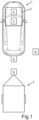
- System 2 includes a trailer coupling assistant 4, which is designed to detect a position of a trailer-side coupling element 5 and based on this to maneuver motor vehicle 1 at least partially autonomously into a target position in which a trailer coupling 6 of the motor vehicle is in a predetermined coupling position to trailer-side coupling element 5 is arranged.
- the trailer coupling 6 of the motor vehicle 1 can be a ball coupling, for example, and the coupling element 5 on the trailer can be a trailer claw, for example.
- Other embodiments of the trailer-side coupling element 5 and the trailer hitch 6 of the motor vehicle 1 are also possible.
- the system 2 also includes a parking aid 7, which is designed to monitor a rear monitoring area B of the motor vehicle 1 (not shown here) during the maneuvering process.
- the system 2 is set up to operate the parking aid 7 in a standard mode when the trailer coupling assistant 4 is deactivated and to operate the parking aid 7 in a coupling mode when the trailer coupling assistant 4 is activated, in which obstacle warnings related to the rear area B are issued differently than in the parking aid 7 by means of the parking aid 7 standard mode are output.
- the trailer coupling assistant 4 can, for example, be coupled to a reversing camera (not shown here), with the trailer coupling assistant 4 itself being able to carry out image processing, for example, in order to recognize the coupling element 5 on the trailer. Based on the detected trailer-side coupling element 5, the trailer coupling assistant 4 can, for example, determine the position of the trailer-side coupling element 5 and, based on this, can maneuver the motor vehicle 1 semi-autonomously or fully autonomously into the said target position, in which the trailer coupling 6 of the motor vehicle 1 is in a predetermined coupling position to the trailer-side coupling element 5 is arranged.
- the trailer hitch 6 of the motor vehicle 1 can be arranged in a specific position below the trailer-side coupling element 5 .
- the trailer 3 can be easily coupled to the motor vehicle 1, for example by lowering a drawbar (not described in more detail here) of the trailer 3 together with the trailer-side coupling element 5 until the trailer-side coupling element 5 hits the trailer coupling 6 of the motor vehicle 1 encloses.
- the parking aid 7 can, for example, have several sensors, not shown here, distributed around the motor vehicle 1, for example in the form of ultrasonic sensors, radar sensors and/or the like, by means of which a wide variety of objects in the vicinity of the motor vehicle 1 can be detected.
- the parking aid 7 is operated in said coupling mode, in which the parking aid 7 is used to issue obstacle warnings relating to the rear area B, which is different from the standard mode.
- the trailer coupling assistant 4 is not just limited to carrying out said maneuvering process to the target position when the driver is seated in the motor vehicle 1 .
- a user or driver of the motor vehicle 1 can activate the trailer coupling assistant 4 with his smartphone 8, so that the trailer coupling assistant 4 carries out the maneuvering process fully automatically, so that the motor vehicle 1 drives fully autonomously to said target position, in which the trailer coupling 6 of the motor vehicle 1 is arranged in the predetermined coupling position with respect to the coupling element 5 on the trailer side.
- warnings or obstacle warnings are transmitted from the parking aid 7 to the smartphone 8 and are output optically and acoustically by means of the latter.
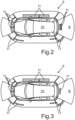
- a display 9 of the motor vehicle 1 is shown, by means of which an image 10 of the motor vehicle 1 is displayed.
- the display 9 can be arranged, for example, in the area of a center console of the motor vehicle 1 .
- the display 9, controlled by the parking aid 7, shows different visual warnings in the form of respective warning bars 11.
- the warning bars 11 are displayed in different colors, from green to yellow to red, depending on how great the respective distances are between objects in the vicinity of the motor vehicle 1 and the motor vehicle 1 are.
- the position of the trailer-side coupling element 5 is transmitted to the parking aid 7 in the coupling mode, and if there is an object in the rear monitoring area B and within a predetermined radius around the position of the trailer-side coupling element 5, the Parking aid 7 omits an output of an obstacle warning, which would otherwise be output in the standard mode.
- the parking aid 7 would display the warning bar 11 in the rear area of the image 10 of the motor vehicle in red, for example, when reversing if the distance to a specific object is less than a specific one.
- the trailer coupling assistant 4 is active, it is provided that the parking aid 7 virtually ignores the immersion of the trailer-side coupling element 5 in the monitoring area B. If, for example, a bumper of the motor vehicle 1 is less than 30 centimeters from the trailer-side coupling element 5, the parking aid 7, which is operated in the coupling mode, still emits neither a visual nor an audible warning.
- the parking aid 7 refrains from outputting both an acoustic and a visual obstacle warning, which would otherwise be output in the standard mode. So there is neither a continuous warning tone nor the display of warning bars 11 in the rear area of the image of the motor vehicle 1 by means of the display 9. A certain area around the trailer-side coupling element 5 is therefore masked or ignored by the parking aid 7 as long as the trailer coupling assistant 4 is active. in particular when this maneuvers the motor vehicle 1 semi-automatically or fully automatically into said target position.
- the display 9 of the motor vehicle 1 is shown again, whereby in the case shown here it is provided that in the coupling mode of the parking aid 7 the position of the trailer-side coupling element 5 is transmitted to the parking aid 7 and a lower distance value to an object from which in the standard mode at the Parking aid 7 a highest warning level is reached, based on the trailer-side coupling element 5 is reduced so much that the highest warning level in the coupling mode is only reached when the motor vehicle 1 has reached the target position.
- the parking aid 7 would already emit this continuous warning tone in the standard mode, for example, if the distance between a rear bumper of the motor vehicle 1 and an object arranged in the rear monitoring area B had fallen below 30 centimeters, for example.
- a visual obstacle warning for example in the form of the warning bar 11 in the rear area of the image 10 of the motor vehicle 1, by means of the display 9 initially in green, then in yellow and finally is displayed in red as soon as the motor vehicle 1 has reached the target position.
- it is therefore provided, in other words, to shift a threshold for the highest acoustic and optical warning level to the target position of motor vehicle 1, in which trailer hitch 6 of motor vehicle 1 is arranged in the specified coupling position to trailer-side coupling element 5.
- a continuous tone sounds, since only then is the highest warning level reached. The same applies to the visual representation.
- the warning bar 11 in the rear area of the image 10 of the motor vehicle 1 is shown in red by means of the display 9 when the motor vehicle 1 has been maneuvered into the target position in which the trailer hitch 6 of the motor vehicle 1 is arranged in the predetermined coupling position to the trailer-side coupling element 5 .
Landscapes
- Engineering & Computer Science (AREA)
- Transportation (AREA)
- Mechanical Engineering (AREA)
- Chemical & Material Sciences (AREA)
- Combustion & Propulsion (AREA)
- Automation & Control Theory (AREA)
- Physics & Mathematics (AREA)
- General Physics & Mathematics (AREA)
- Mathematical Physics (AREA)
- Human Computer Interaction (AREA)
- Traffic Control Systems (AREA)
- Control Of Driving Devices And Active Controlling Of Vehicle (AREA)
Description
- Die Erfindung betrifft ein Verfahren und System zum Unterstützen eines Ankoppelvorgangs eines Kraftfahrzeugs an einen Anhänger der in den Oberbegriffen der unabhängigen Patentansprüche angegebenen Art. Des Weiteren betrifft die Erfindung noch ein Kraftfahrzeug mit einem derartigen System.
- Verfahren und Systeme zum Unterstützen eines Ankoppelvorgangs eines Kraftfahrzeugs an einen Anhänger sind an sich schon bekannt. So beschreibt die
DE 10 2009 045 284 A1 beispielsweise ein automatisiertes System zum Unterstützen eines Ankoppelvorgangs eines Kraftfahrzeugs an einen Anhänger. Das automatisierte System nimmt notwendige Lenkeingriffe zum Manövrieren des Kraftfahrzeugs an den Anhänger automatisch vor, wobei ein Fahrer lediglich die Aufgabe hat, die Längsführung des Kraftfahrzeugs zu übernehmen, das heißt, das Fahrzeug sinnvoll zu beschleunigen oder abzubremsen. Zudem kann der Abstand des Kraftfahrzeugs zum Anhänger optisch und akustisch dargestellt werden. - Weitere Verfahren und Systeme zum Unterstützen eines Ankoppelvorgangs eines Kraftfahrzeugs an einen Anhänger sind beispielsweise noch in der
DE 10 2005 052 238 A1 ,DE 10 2009 030 452 A1 ,DE 10 2010 004 920 A1 sowie in derDE 10 2004 008 928 A1 gezeigt. - Es ist die Aufgabe der vorliegenden Erfindung, eine Lösung bereitzustellen, mittels welcher ein Benutzer besonders gut bei einem Ankoppelvorgang eines Kraftfahrzeugs an einen Anhänger unterstützt wird.
- Diese Aufgabe wird durch ein Verfahren sowie durch ein System zum Unterstützen eines Ankoppelvorgangs eines Kraftfahrzeugs an einen Anhänger mit den Merkmalen der unabhängigen Patentansprüche gelöst. Vorteilhafte Ausgestaltungen mit zweckmäßigen und nicht-trivialen Weiterbildungen der Erfindung sind in den übrigen Ansprüchen angegeben.
- Bei dem erfindungsgemäßen Verfahren zum Unterstützen eines Ankoppelvorgangs eines Kraftfahrzeugs an einen Anhänger wird mittels eines Anhängerankuppelassistenten eine Position eines anhängerseitigen Kupplungselements erkannt und basierend darauf das Kraftfahrzeug zumindest teilautonom in eine Zielposition manövriert, in welcher eine Anhängerkupplung des Kraftfahrzeugs in einer vorgegebenen Ankoppelstellung zum anhängerseitigen Kupplungselement angeordnet ist. Beispielsweise kann eine Rückfahrkamera in Kombination mit einer Bildverarbeitung verwendet werden, um die Position des anhängerseitigen Kupplungselements, beispielsweise in Form einer Anhängerkralle oder dergleichen, zu erkennen. Basierend auf dieser erkannten Position des anhängerseitigen Kupplungselements und in Kenntnis der relativen Positionierung der Anhängerkupplung des Kraftfahrzeugs zum anhängerseitigen Kupplungselement kann der Anhängerankuppelassistent eine Trajektorie planen, welche das Kraftfahrzeug entlang fahren muss, um die besagte Zielposition zu erreichen.
- Während des Manövriervorgangs wird mittels einer Einparkhilfe ein rückwärtiger Überwachungsbereich des Kraftfahrzeugs überwacht. Die Einparkhilfe kann beispielsweise Ultraschallsensoren, Radarsensoren oder dergleichen aufweisen, um den rückwärtigen Überwachungsbereich des Kraftfahrzeugs während des Manövriervorgangs zu überwachen. Der Anhängerankuppelassistent kann den Manövriervorgang teilautonom oder auch vollautonom vornehmen. Beispielsweise ist es möglich, dass ein Fahrer des Kraftfahrzeugs lediglich das Gaspedal und die Bremse betätigen muss, wobei der Anhängerankuppelassistent sämtliche Lenkvorgänge zur Erreichung der Zielposition vollautomatisch durchführt. Alternativ ist es aber auch möglich, dass der Anhängerankuppelassistent den gesamten Manövriervorgang vollautomatisch durchführt. Dabei kann der Fahrer beispielsweise im Kraftfahrzeug sitzen. Alternativ ist es aber auch möglich, dass ein Benutzer das Kraftfahrzeug und somit den Anhängerankuppelassistenten beispielsweise mit seinem Smartphone fernsteuern kann, wobei der Anhängerankuppelassistent den Manövriervorgang solange vollautomatisch bis zum Erreichen der Zielposition durchführt, solange erfasst wird, dass der Benutzer beispielsweise seinen Finger auf eine bestimmte mechanische oder nur angezeigte Bedientaste des Smartphones gelegt hat.
- Das erfindungsgemäße Verfahren zeichnet sich dadurch aus, dass die Einparkhilfe bei deaktiviertem Anhängerankuppelassistenten in einem Standardmodus betrieben wird, wohingegen die Einparkhilfe bei aktiviertem Anhängerankuppelassistenten in einem Ankoppelmodus betrieben wird, in welchem mittels der Einparkhilfe auf den rückwärtigen Bereich bezogene Hinderniswarnungen anders als im Standardmodus ausgegeben werden. Mit anderen Worten ist es also erfindungsgemäß vorgesehen, die Einparkhilfe während des Manövriervorgangs mittels des Anhängerankuppelassistenten anders zu betreiben, als es standardmäßig beim reinen Rückwärtsfahren oder ganz allgemein beim Rangieren mit aktivierter Einparkhilfe der Fall wäre.
- Der Erfindung liegt dabei die Erkenntnis zugrunde dass es bei einer rein herkömmlichen Betriebsweise der Einparkhilfe bei gleichzeitig aktiviertem Anhängerankuppelassistenten zu widersprüchlichen Hinderniswarnungen für einen Benutzer des Kraftfahrzeugs kommen kann. Würde nämlich die Einparkhilfe sowohl bei aktivierten als auch bei deaktivierten Anhängerankuppelassistenten im besagten Standardmodus betrieben werden, könnte es beispielsweise vorkommen, dass beim Rückwärtsmanövrieren des Kraftfahrzeugs an den Anhänger heran bei Unterschreiten eines bestimmten Abstands zum Anhänger, insbesondere zum anhängerseitigen Kupplungselement, ein Dauerwarnton ausgegeben wird. Dies stellt üblicherweise die höchste Warnstufe bei gängigen Einparkhilfen dar und bedeutet dem Fahrer, dass er nicht mehr weiterfahren sollte. Handelt es sich jedoch bei dem erkannten Hindernis um das anhängerseitige Kupplungselement, so muss der Fahrer jedoch trotz des Dauerwarntons weiterfahren, da er die besagte Zielposition noch nicht erreicht hat, in welcher die Anhängerkupplung des Kraftfahrzeugs in der vorgegebenen Ankoppelstellung zum anhängerseitigen Kupplungselement angeordnet ist. Trotz der höchsten Warnstufe müsste der Fahrer also weiterfahren, da ab Ertönen des Dauerwarntons die besagte Zielposition beispielsweise noch 10 bis 15 Zentimeter entfernt ist.
- Genau diese Problematik greift die erfindungsgemäßen Lösung auf. Denn dadurch, dass die Einparkhilfe bei aktiviertem Anhängerankuppelassistenten im besagten Ankoppelmodus betrieben wird, in welchem mittels der Einparkhilfe auf den rückwärtigen Bereich bezogene Hinderniswarnungen anders als im Standardmodus ausgegeben werden, können beim Heranmanövrieren des Kraftfahrzeugs mittels des Anhängerankuppelassistenten widerspruchsfreie Hinderniswarnungen ausgegeben werden. Beim Heranmanövrieren an den Anhänger gibt die Einparkhilfe also andere Hinderniswarnungen aus, als es diese beispielsweise beim reinen Rückwärtsfahren tun würde, beispielsweise wenn sich das Kraftfahrzeug einer Wand oder dergleichen nähert.
- Das wird dadurch erzielt, dass der Einparkhilfe mitgeteilt wird, ob der Anhängerankuppelassistent gerade aktiv ist oder nicht, insbesondere ob der Anhängerankuppelassistent gerade das Kraftfahrzeug zumindest teilautonom in Richtung der Zielposition manövriert. Eine Warnstrategie der Einparkhilfe kann somit an den aktivierten Anhängerankuppelassistenten angepasst werden, sodass ein Fahrer beziehungsweise Benutzer des Kraftfahrzeugs während des Manövriervorgangs in die Zielposition nicht durch gegebenenfalls widersprüchliche Hinderniswarnungen von der Einparkhilfe irritiert wird. Denn während des Ankoppelvorgangs an den Anhänger ist es gerade erforderlich, dass das Kraftfahrzeug einen üblichen Minimalabstand, ab welchem eine höchste Warnstufe der Einparkhilfe im Standmodus erreicht wird, zum anhängerseitigen Kupplungselement unterschreitet.
- Die Erfindung sieht zudem vor, dass im Ankoppelmodus die Position des anhängerseitigen Kupplungselements an die Einparkhilfe übermittelt wird, wobei, wenn sich ein Objekt im rückwärtigen Überwachungsbereich und innerhalb eines vorgegebenen Umkreises um die Position des anhängerseitigen Kupplungselements befindet, die Einparkhilfe eine Ausgabe einer Hinderniswarnung unterlässt, welche im Standardmodus ansonsten ausgegeben werden würde. Mit anderen Worten ist also eine Art Ausmaskierung des anhängerseitigen Ankupplungselements vorgesehen. Die Einparkhilfe kann in Kenntnis der Position des anhängerseitigen Ankupplungselements die Ausgabe von Hinderniswarnungen anpassen. Werden in der Nähe des anhängerseitigen Ankupplungselements Objekte erkannt, auf welche die Einparkhilfe üblicherweise mit Hinderniswarnungen reagieren würde, wird die Warnstrategie der Einparkhilfe im Ankoppelmodus derart angepasst, dass keine auf diese Objekte bezogenen Hinderniswarnungen ausgegeben werden. Der Fahrer des Kraftfahrzeugs beziehungsweise der Benutzer des Kraftfahrzeugs wird also während des Manövriervorgangs mittels des Anhängerankuppelassistenten in Richtung der Zielposition nicht durch die Einparkhilfe irritiert, da diese insbesondere die Annäherung an das anhängerseitige Kupplungselement insofern ignoriert, dass diesbezüglich keine Hinderniswarnungen ausgegeben werden.
- Eine vorteilhafte Ausführungsform der Erfindung sieht vor, dass, wenn sich ein Objekt im rückwärtigen Überwachungsbereich und innerhalb des vorgegebenen Umkreises um die Position des anhängerseitigen Kupplungselements befindet, die Einparkhilfe die Ausgabe einer akustischen Hinderniswarnung, insbesondere eines Dauerwarntons, unterlässt, welche im Standardmodus ansonsten ausgegeben werden würde. Alternativ oder zusätzlich ist es vorgesehen, dass, wenn sich ein Objekt im rückwärtigen Überwachungsbereich und innerhalb des vorgegebenen Umkreises um die Position des anhängerseitigen Kupplungselements befindet, die Einparkhilfe das Anzeigen einer optischen Hinderniswarnung unterlässt, insbesondere in gelben und/oder roten Signalfarben, welche im Standardmodus ansonsten angezeigt werden würde. Unterschreitet das Kraftfahrzeug beispielsweise mit einer hinteren Stoßstange einen Abstand zum anhängerseitigen Kupplungselement von 30 Zentimetern, könnte es im Standardmodus der Einparkhilfe vorgesehen sein, dass diese sowohl einen Dauerton ausgibt als auch beispielsweise in einem fahrzeugseitigen Display entsprechend rote Warnbalken anzeigt. Im Ankoppelmodus der Einparkhilfe, also bei aktiviertem Anhängerankuppelassistenten hingegen, werden derartige Hinderniswarnungen, welche auf eine Unterschreitung eines bestimmten Abstands zum anhängerseitigen Kupplungselement bezogen sind, unterlassen. Ein Fahrer beziehungsweise Benutzer des Kraftfahrzeugs wird also während des zumindest teilautonomen Manövriervorgangs des Kraftfahrzeugs zur Zielposition nicht durch akustische und/oder optische Hinderniswarnungen irritiert, welche auf eine Unterschreitung eines bestimmten Abstands zum anhängerseitigen Kupplungselement bezogen sind.
- In weiterer vorteilhafter Ausgestaltung der Erfindung ist es vorgesehen, dass die Hinderniswarnung im Kraftfahrzeug und bei einem mittels einer Fernbedienung ferngesteuerten Manövriervorgang die Hinderniswarnung mittels der Fernbedienung ausgegeben wird. Beispielsweise ist es möglich, dass ein Benutzer des Kraftfahrzeugs den Ankoppelvorgang über sein Smartphone fernsteuern kann. In dem Fall werden die vorstehend beschriebenen Hinderniswarnungen vorzugsweise auch mittels des Smartphones ausgegeben, wobei auch in diesem Fall die Einparkhilfe bei aktiviertem Anhängerankuppelassistenten im besagten Ankoppelmodus betrieben wird, in welchem mittels der Einparkhilfe auf den rückwärtigen Bereich bezogene Hinderniswarnungen anders als im Standardmodus ausgegeben werden. So wird auch bei einer Fernbedienung des Kraftfahrzeugs mittels des Smartphones die akustische und/oder optische Hinderniswarnung mittels der Einparkhilfe während des Manövriervorgangs in die Zielposition anders ausgegeben, als wenn beispielsweise mittels des Smartphones ein Remote-Einparkvorgang vorgenommen wird. Steht ein Fahrer beziehungsweise Benutzer des Kraftfahrzeugs also außerhalb vom Kraftfahrzeug, während das Kraftfahrzeug an den Anhänger heran rangiert wird, so wird der Benutzer auch dann durch eine angepasste Warnstrategie seitens der Einparkhilfe nicht durch widersprüchliche, über das Smartphone ausgegebene Hinderniswarnungen irritiert.
- Das erfindungsgemäße System zum Unterstützen eines Ankoppelvorgangs eines Kraftfahrzeugs an einen Anhänger umfasst einen Anhängerankuppelassistenten, welcher dazu ausgelegt ist, eine Position eines anhängerseitigen Kupplungselements zu erkennen und basierend darauf das Kraftfahrzeug zumindest teilautonom in eine Zielposition zu manövrieren, in welcher eine Anhängerkupplung des Kraftfahrzeugs in einer vorgegebenen Ankoppelstellung zum anhängerseitigen Kupplungselement angeordnet ist, wobei das System eine Einparkhilfe aufweist, welche dazu ausgelegt ist, während des Manövriervorgangs einen rückwärtigen Überwachungsbereich des Kraftfahrzeugs zu überwachen. Das System ist dabei dazu eingerichtet, die Einparkhilfe bei deaktiviertem Anhängerankuppelassistenten in einem Standardmodus und die Einparkhilfe bei aktiviertem Anhängerankuppelassistenten in einem Ankoppelmodus zu betreiben, in welchem mittels der Einparkhilfe auf den rückwärtigen Bereich bezogene Hinderniswarnungen anders als im Standardmodus ausgegeben werden. Das System ist außerdem dazu eingerichtet, im Ankoppelmodus die Position des anhängerseitigen Kupplungselements an die Einparkhilfe zu übermitteln, wobei, wenn sich ein Objekt im rückwärtigen Überwachungsbereich und innerhalb eines vorgegebenen Umkreises um die Position des anhängerseitigen Kupplungselements befindet, die Einparkhilfe dazu ausgelegt ist, eine Ausgabe einer Hinderniswarnung zu unterlassen, welche im Standardmodus ansonsten ausgegeben werden würde, indem die Annäherung an das anhängerseitige Kupplungselement insofern ignoriert wird, dass diesbezüglich keine Hinderniswarnungen ausgegeben werden. Vorteilhafte Ausgestaltungen des erfindungsgemäßen Verfahrens sind als vorteilhafte Ausgestaltungen des erfindungsgemäßen Systems und umgekehrt anzusehen, wobei das System insbesondere Mittel zur Durchführung der Verfahrensschritte aufweist.
- Das erfindungsgemäße Kraftfahrzeug umfasst das erfindungsgemäße System oder eine vorteilhafte Ausführungsform des erfindungsgemäßen Systems zum Unterstützen eines Ankoppelvorgangs eines Kraftfahrzeugs an einen Anhänger.
- Die Zeichnung zeigt in:
- Fig. 1
- eine schematische Darstellung eines Ankoppelvorgangs eines Kraftfahrzeugs an einen Anhänger;
- Fig. 2
- eine Darstellung eines Displays des Kraftfahrzeugs, mittels welchem während des Ankoppelvorgangs an den Anhänger optische Hinderniswarnungen ausgegeben werden; und in
- Fig. 3
- eine weitere Darstellung des Displays des Kraftfahrzeugs, mittels welchem gemäß einer zweiten Variante optische Hinderniswarnungen während des Heranfahrens an den Anhänger ausgegeben werden.
- In den Figuren sind gleiche oder funktionsgleiche Elemente mit den gleichen Bezugszeichen versehen worden.
- Ein Kraftfahrzeug 1, das ein System 2 zum Unterstützen eines Ankoppelvorgangs des Kraftfahrzeugs 1 an einen Anhänger 3 aufweist, ist in einer schematischen Darstellung in
Fig. 1 gezeigt. Das System 2 umfasst einen Anhängerankuppelassistenten 4, welcher dazu ausgelegt ist, eine Position eines anhängerseitigen Kupplungselements 5 zu erkennen und basierend darauf das Kraftfahrzeug 1 zumindest teilautonom in eine Zielposition zu manövrieren, in welcher eine Anhängerkupplung 6 des Kraftfahrzeugs in einer vorgegebenen Ankoppelstellung zum anhängerseitigen Kupplungselement 5 angeordnet ist. Bei der Anhängerkupplung 6 des Kraftfahrzeugs 1 kann es sich beispielsweise um eine Kugelkupplung und bei dem anhängerseitigen Kupplungselement 5 beispielsweise um eine Anhängerkralle handeln. Andere Ausführungsformen des anhängerseitigen Kupplungselements 5 und der Anhängerkupplung 6 des Kraftfahrzeugs 1 sind ebenfalls möglich. - Das System 2 umfasst zudem noch eine Einparkhilfe 7, welche dazu ausgelegt ist, während des Manövriervorgangs einen rückwärtigen, hier nicht dargestellten Überwachungsbereich B des Kraftfahrzeugs 1 zu überwachen. Das System 2 ist dabei dazu eingerichtet, die Einparkhilfe 7 bei deaktiviertem Anhängerankuppelassistenten 4 in einem Standardmodus zu betreiben und die Einparkhilfe 7 bei aktiviertem Anhängerankuppelassistenten 4 in einem Ankoppelmodus zu betreiben, in welchem mittels der Einparkhilfe 7 auf den rückwärtigen Bereich B bezogene Hinderniswarnungen anders als im Standardmodus ausgegeben werden.
- Der Anhängerankuppelassistent 4 kann beispielsweise mit einer hier nicht dargestellten Rückfahrkamera gekoppelt sein, wobei der Anhängerankuppelassistent 4 selbst beispielsweise eine Bildverarbeitung vornehmen kann, um das anhängerseitige Kupplungselement 5 zu erkennen. Basierend auf dem erkannten anhängerseitigen Kupplungselement 5 kann der Anhängerankuppelassistent 4 beispielsweise die Position des anhängerseitigen Kupplungselements 5 bestimmen und basierend darauf das Kraftfahrzeug 1 teilautonom oder vollautonom in die besagte Zielposition manövrieren, in welcher die Anhängerkupplung 6 des Kraftfahrzeugs 1 in einer vorgegebenen Ankoppelstellung zum anhängerseitigen Kupplungselement 5 angeordnet ist.
- In der Zielposition kann es beispielsweise vorgesehen sein, dass die Anhängerkupplung 6 des Kraftfahrzeugs 1 in einer bestimmten Position unterhalb von dem anhängerseitigen Kupplungselement 5 angeordnet sein muss. Ist diese Zielposition erreicht, so kann der Anhänger 3 ganz einfach an das Kraftfahrzeug 1 angekoppelt werden, beispielsweise indem eine hier nicht näher bezeichnete Deichsel des Anhängers 3 mitsamt dem anhängerseitigen Kupplungselement 5 soweit abgesenkt wird, bis das anhängerseitige Kupplungselement 5 die Anhängerkupplung 6 des Kraftfahrzeugs 1 umschließt.
- Die Einparkhilfe 7 kann beispielsweise rund ums Kraftfahrzeug 1 verteilt mehrere hier nicht dargestellte Sensoren, beispielsweise in Form von Ultraschallsensoren, Radarsensoren und/oder dergleichen aufweisen, mittels welchen unterschiedlichste Objekte in der Nähe des Kraftfahrzeugs 1 detektiert werden können. Um einen Fahrer beziehungsweise Benutzer des Kraftfahrzeugs 1 während des Manövriervorgangs in die besagte Zielposition nicht zu irritieren, ist es vorgesehen, die Einparkhilfe bei deaktiviertem Anhängerankuppelassistenten anders zu betreiben als bei aktiviertem Anhängerankuppelassistenten. In letzterem Fall wird die Einparkhilfe 7 im besagten Ankoppelmodus betrieben, in welchem mittels der Einparkhilfe 7 auf den rückwärtigen Bereich B bezogene Hinderniswarnungen anders als im Standardmodus ausgegeben werden.
- Der Anhängerankuppelassistent 4 ist dabei nicht nur darauf beschränkt, bei im Kraftfahrzeug 1 sitzendem Fahrer den besagten Manövriervorgang in die Zielposition vorzunehmen. Alternativ oder zusätzlich kann es auch vorgesehen sein, dass ein Benutzer beziehungsweise Fahrer des Kraftfahrzeugs 1 mit seinem Smartphone 8 den Anhängerankuppelassistenten 4 aktivieren kann, sodass der Anhängerankuppelassistent 4 vollautomatisch den Manövriervorgang vornimmt, sodass das Kraftfahrzeug 1 die besagte Zielposition vollautonom anfährt, in welcher die Anhängerkupplung 6 des Kraftfahrzeugs 1 in der vorgegebenen Ankoppelstellung zum anhängerseitigen Kupplungselement 5 angeordnet ist. Bei der Steuerung mittels des Smartphones 8 kann es vorgesehen sein, dass Warnhinweise beziehungsweise Hinderniswarnungen von der Einparkhilfe 7 an das Smartphone 8 übertragen und mittels diesem optisch und akustisch ausgegeben werden. Auch in diesem Fall ist es vorgesehen, dass die Einparkhilfe 7 bei deaktiviertem Anhängerankuppelassistenten 4 anders betrieben wird als bei aktiviertem Anhängerankuppelassistenten 4, nämlich im letzteren Fall im besagten Ankoppelmodus.
- In
Fig. 2 ist ein Display 9 des Kraftfahrzeugs 1 dargestellt, mittels welchem ein Abbild 10 des Kraftfahrzeugs 1 angezeigt wird. Das Display 9 kann beispielsweise im Bereich einer Mittelkonsole des Kraftfahrzeugs 1 angeordnet sein. Während des Manövrier- beziehungsweise Rangiervorgangs in Richtung des Anhängers 3 zeigt das Display 9, angesteuert durch die Einparkhilfe 7, unterschiedliche optische Warnhinweise in Form jeweiliger Warnbalken 11 an. In an sich bekannter Weise kann es beim normalen Rangieren mit dem Kraftfahrzeug 1 vorgesehen sein, dass die Warnbalken 11 in unterschiedlichen Farben, von grün über gelb bis hin zu rot dargestellt werden, je nachdem wie groß jeweilige Abstände zwischen Objekten im Umfeld des Kraftfahrzeugs 1 und dem Kraftfahrzeug 1 sind. - Bei der hier gezeigten Ausführungsform ist es vorgesehen, dass im Ankoppelmodus die Position des anhängerseitigen Kupplungselements 5 an die Einparkhilfe 7 übermittelt wird, wobei, wenn sich ein Objekt im rückwärtigen Überwachungsbereich B und innerhalb eines vorgegebenen Umkreises um die Position des anhängerseitigen Kupplungselements 5 befindet, die Einparkhilfe 7 eine Ausgabe einer Hinderniswarnung unterlässt, welche im Standardmodus ansonsten ausgegeben werden würde.
- Beispielsweise könnte es im Standardmodus vorgesehen sein, dass die Einparkhilfe 7 beim Rückwärtsfahren bei Unterschreiten eines bestimmten Abstands zu einem bestimmten Objekt die Warnbalken 11 im Heckbereich des Abbilds 10 des Kraftfahrzeugs zum Beispiel in rot anzeigen würde. Ist der Anhängerankuppelassistent 4 jedoch aktiv, so ist es vorgesehen, dass die Einparkhilfe 7 insbesondere das Eintauchen des anhängerseitigen Kupplungselements 5 in den Überwachungsbereich B quasi ignoriert. Unterschreitet beispielsweise eine Stoßstange des Kraftfahrzeugs 1 einen Abstand von 30 Zentimetern zum anhängerseitigen Kupplungselement 5, wird dennoch mittels der Einparkhilfe 7, welche im Ankoppelmodus betrieben wird, weder ein optischer noch ein akustischer Warnhinweis ausgegeben. Wenn sich also ein Objekt im rückwärtigen Überwachungsbereich B und innerhalb des vorgegebenen Umkreises um die Position des anhängerseitigen Kupplungselements 5 befindet, unterlässt die Einparkhilfe 7 sowohl die Ausgabe einer akustischen als auch einer optischen Hinderniswarnung, welche im Standardmodus ansonsten ausgegeben werden würde. Es ertönt also weder ein Dauerwarnton noch das Anzeigen von Warnbalken 11 im Heckbereich des Abbilds des Kraftfahrzeugs 1 mittels des Displays 9. Ein bestimmter Bereich rund um das anhängerseitige Kupplungselement 5 wird also mittels der Einparkhilfe 7 maskiert beziehungsweise ignoriert, solange der Anhängerankuppelassistent 4 aktiv ist, insbesondere wenn dieser das Kraftfahrzeug 1 in die besagte Zielposition teilautomatisch oder vollautomatisch rangiert.
- In
Fig. 3 ist das Display 9 des Kraftfahrzeugs 1 erneut dargestellt, wobei es im hier gezeigten Fall vorgesehen ist, dass im Ankoppelmodus der Einparkhilfe 7 die Position des anhängerseitigen Kupplungselements 5 an die Einparkhilfe 7 übermittelt und ein unterer Abstandswert zu einem Objekt, ab welchem im Standardmodus bei der Einparkhilfe 7 eine höchste Warnstufe erreicht ist, bezogen auf das anhängerseitige Kupplungselement 5 so sehr verringert wird, dass die höchste Warnstufe im Ankoppelmodus erst dann erreicht wird, wenn das Kraftfahrzeug 1 die Zielposition erreicht hat. - Dabei kann es vorgesehen sein, dass mit sich verringerndem Abstand zur Position des anhängerseitigen Kupplungselements 5 Pausen zwischen einer ausgegebenen akustischen Hinderniswarnung verringert werden, wobei die akustische Hinderniswarnung als Dauerwarnton ausgegeben wird, sobald das Kraftfahrzeug die Zielposition erreicht hat. Im Gegensatz dazu würde die Einparkhilfe 7 im Standardmodus diesen Dauerwarnton beispielsweise schon dann ausgeben, wenn zwischen einer hinteren Stoßstange des Kraftfahrzeugs 1 und einem im rückwärtigen Überwachungsbereich B angeordneten Objekt ein Abstand von beispielsweise 30 Zentimetern unterschritten worden wäre.
- Zudem kann es auch noch vorgesehen sein, dass mit sich verringerndem Abstand zur Position des anhängerseitigen Kupplungselements 5 eine optische Hinderniswarnung, beispielsweise in Form des Warnbalkens 11 im Heckbereich des Abbilds 10 des Kraftfahrzeugs 1 mittels des Displays 9 zunächst in grün, dann in gelb und schließlich in rot angezeigt wird, sobald das Kraftfahrzeug 1 die Zielposition erreicht hat. Bei dem im Zusammenhang mit
Fig. 3 beschriebenen Ausführungsbeispiel ist es also mit anderen Worten vorgesehen, eine Schwelle zur höchsten akustischen als auch optischen Warnstufe auf die Zielposition des Kraftfahrzeugs 1 zu verschieben, in welcher die Anhängerkupplung 6 des Kraftfahrzeugs 1 in der vorgegebenen Ankoppelstellung zum anhängerseitigen Kupplungselement 5 angeordnet ist. Bei Erreichen der Zielposition ertönt ein Dauerton, da erst dann die höchste Warnstufe erreicht wird. Gleiches gilt auch für die optische Darstellung. So wird der Warnbalken 11 im Heckbereich des Abbilds 10 des Kraftfahrzeugs 1 mittels des Displays 9 in rot angezeigt, wenn das Kraftfahrzeug 1 in die Zielposition manövriert worden ist, in der die Anhängerkupplung 6 des Kraftfahrzeugs 1 in der vorgegebenen Ankoppelstellung zum anhängerseitigen Kupplungselement 5 angeordnet ist. - Mittels beider im Zusammenhang mit den
Fig. 2 und 3 beschriebenen Vorgehensweisen kann sichergestellt werden, dass ein Benutzer beziehungsweise Fahrer des Kraftfahrzeugs 1 während eines zumindest teilautonomen Ankoppelvorgangs an den Anhänger 3 nicht durch widersprüchliche Warnhinweise mittels der Einparkhilfe 7 irritiert wird. -
- 1
- Kraftfahrzeug
- 2
- System
- 3
- Anhänger
- 4
- Anhängerankuppelassistent
- 5
- anhängerseitiges Kupplungselement
- 6
- Anhängerkupplung des Kraftfahrzeugs
- 7
- Einparkhilfe
- 8
- Smartphone
- 9
- Display des Kraftfahrzeugs
- 10
- Abbild des Kraftfahrzeugs
- 11
- Warnbalken
- B
- rückwärtiger Überwachungsbereich
Claims (6)
- Verfahren zum Unterstützen eines Ankoppelvorgangs eines Kraftfahrzeugs (1) an einen Anhänger (3), bei welchem mittels eines Anhängerankuppelassistenten (4) eine Position eines anhängerseitigen Kupplungselements (5) erkannt und basierend darauf das Kraftfahrzeug (1) zumindest teilautonom in eine Zielposition manövriert wird, in welcher eine Anhängerkupplung (6) des Kraftfahrzeugs (1) in einer vorgegebenen Ankoppelstellung zum anhängerseitigen Kupplungselement (5) angeordnet ist, wobei während des Manövriervorgangs mittels einer Einparkhilfe (7) ein rückwärtiger Überwachungsbereich (B) des Kraftfahrzeugs (1) überwacht wird, wobei- die Einparkhilfe (7) bei deaktiviertem Anhängerankuppelassistenten (4) in einem Standardmodus betrieben wird;- die Einparkhilfe (7) bei aktiviertem Anhängerankuppelassistenten (4) in einem Ankoppelmodus betrieben wird, in welchem mittels der Einparkhilfe (7) auf den rückwärtigen Bereich (B) bezogene Hinderniswarnungen anders als im Standardmodus ausgegeben werden;wobei im Ankoppelmodus die Position des anhängerseitigen Kupplungselements (5) an die Einparkhilfe (7) übermittelt wird,dadurch gekennzeichnet, dassdann, wenn sich ein Objekt im rückwärtigen Überwachungsbereich (B) und innerhalb eines vorgegebenen Umkreises um die Position des anhängerseitigen Kupplungselements (5) befindet, die Einparkhilfe (7) eine Ausgabe einer Hinderniswarnung unterlässt, welche im Standardmodus ansonsten ausgegeben werden würde, indem die Annäherung an das anhängerseitige Kupplungselement (5) insofern ignoriert wird, dass diesbezüglich keine Hinderniswarnungen ausgegeben werden.
- Verfahren nach Anspruch 1,
dadurch gekennzeichnet, dass,
wenn sich ein Objekt im rückwärtigen Überwachungsbereich (B) und innerhalb des vorgegebenen Umkreises um die Position des anhängerseitigen Kupplungselements (5) befindet, die Einparkhilfe (7) die Ausgabe einer akustischen Hinderniswarnung, insbesondere eines Dauerwarntons, unterlässt, welche im Standardmodus ansonsten ausgegeben werden würde. - Verfahren nach Anspruch 1 oder 2,
dadurch gekennzeichnet, dass,
wenn sich ein Objekt im rückwärtigen Überwachungsbereich (B) und innerhalb des vorgegebenen Umkreises um die Position des anhängerseitigen Kupplungselements (5) befindet, die Einparkhilfe (7) das Anzeigen einer optischen Hinderniswarnung (11) unterlässt, insbesondere in gelben und/oder roten Signalfarben, welche im Standardmodus ansonsten angezeigt werden würde. - Verfahren nach einem der vorhergehenden Ansprüche,
dadurch gekennzeichnet, dass
die Hinderniswarnung im Kraftfahrzeug (1) und bei einem mittels einer Fernbedienung (8) ferngesteuerten Manövriervorgang die Hinderniswarnung mittels der Fernbedienung (8) ausgegeben wird. - System (2) zum Unterstützen eines Ankoppelvorgangs eines Kraftfahrzeugs (1) an einen Anhänger (3), umfassend einen Anhängerankuppelassistenten (4), welcher dazu ausgelegt ist, eine Position eines anhängerseitigen Kupplungselements (5) zu erkennen und basierend darauf das Kraftfahrzeug (1) zumindest teilautonom in eine Zielposition zu manövrieren, in welcher eine Anhängerkupplung (6) des Kraftfahrzeugs (1) in einer vorgegebenen Ankoppelstellung zum anhängerseitigen Kupplungselement (5) angeordnet ist, wobei das System (2) eine Einparkhilfe (7) aufweist, welche dazu ausgelegt ist, während des Manövriervorgangs einen rückwärtigen Überwachungsbereich (B) des Kraftfahrzeugs (1) zu überwachen, wobeidas System dazu eingerichtet ist,- die Einparkhilfe (7) bei deaktiviertem Anhängerankuppelassistenten (4) in einem Standardmodus zu betreiben;- die Einparkhilfe (7) bei aktiviertem Anhängerankuppelassistenten (4) in einem Ankoppelmodus zu betreiben, in welchem mittels der Einparkhilfe (7) auf den rückwärtigen Bereich (B) bezogene Hinderniswarnungen anders als im Standardmodus ausgegeben werden;• im Ankoppelmodus die Position des anhängerseitigen Kupplungselements (5) an die Einparkhilfe (7) zu übermitteln,dadurch gekennzeichnet, dassdas System weiterhin eingerichtet ist, dann, wenn sich ein Objekt im rückwärtigen Überwachungsbereich (B) und innerhalb eines vorgegebenen Umkreises um die Position des anhängerseitigen Kupplungselements (5) befindet, die Einparkhilfe (7) dazu ausgelegt ist, eine Ausgabe einer Hinderniswarnung zu unterlassen, welche im Standardmodus ansonsten ausgegeben werden würde, indem die Annäherung an das anhängerseitige Kupplungselement (5) insofern ignoriert wird, dass diesbezüglich keine Hinderniswarnungen ausgegeben werden.
- Kraftfahrzeug (1) mit einem System nach Anspruch 5.
Applications Claiming Priority (1)
| Application Number | Priority Date | Filing Date | Title |
|---|---|---|---|
| DE102018202613.0A DE102018202613B4 (de) | 2018-02-21 | 2018-02-21 | Verfahren und System zum Unterstützen eines Ankoppelvorgangs eines Kraftfahrzeugs an einen Anhänger |
Publications (2)
| Publication Number | Publication Date |
|---|---|
| EP3530549A1 EP3530549A1 (de) | 2019-08-28 |
| EP3530549B1 true EP3530549B1 (de) | 2023-08-09 |
Family
ID=65200670
Family Applications (1)
| Application Number | Title | Priority Date | Filing Date |
|---|---|---|---|
| EP19153130.0A Active EP3530549B1 (de) | 2018-02-21 | 2019-01-22 | Verfahren und system zum unterstützen eines ankoppelvorgangs eines kraftfahrzeugs an einen anhänger |
Country Status (4)
| Country | Link |
|---|---|
| US (1) | US11427255B2 (de) |
| EP (1) | EP3530549B1 (de) |
| CN (2) | CN121224682A (de) |
| DE (1) | DE102018202613B4 (de) |
Families Citing this family (6)
| Publication number | Priority date | Publication date | Assignee | Title |
|---|---|---|---|---|
| JP7205236B2 (ja) * | 2019-01-08 | 2023-01-17 | トヨタ自動車株式会社 | リモート走行システム及びリモート走行アプリケーションソフト |
| US11180148B2 (en) * | 2019-09-03 | 2021-11-23 | Ford Global Technologies, Llc | Detection and response to confined trailer in system-assisted hitch operation |
| US11770991B2 (en) * | 2019-10-31 | 2023-10-03 | Deere & Company | Vehicle connection guidance |
| EP4163133B1 (de) | 2021-10-08 | 2025-08-06 | Bayerische Motoren Werke Aktiengesellschaft | Verfahren zum unterstützen während eines ankoppelvorgangs mit einem anhänger, recheneinrichtung sowie assistenzsystem für ein fahrzeug |
| EP4163134A1 (de) | 2021-10-08 | 2023-04-12 | Bayerische Motoren Werke Aktiengesellschaft | Verfahren zum unterstützen während eines ankoppelvorgangs mit einem anhänger, recheneinrichtung sowie assistenzsystem für ein fahrzeug |
| US20230286584A1 (en) * | 2022-03-08 | 2023-09-14 | Ford Global Technologies, Llc | Method for operating a motor vehicle with a parking assistant |
Family Cites Families (21)
| Publication number | Priority date | Publication date | Assignee | Title |
|---|---|---|---|---|
| DE102004008928A1 (de) * | 2004-02-24 | 2005-09-08 | Bayerische Motoren Werke Ag | Verfahren zum Ankuppeln eines Anhängers unter Einsatz einer Fahrzeugniveauregulierung |
| DE102004043761A1 (de) | 2004-09-10 | 2006-03-16 | Daimlerchrysler Ag | Verfahren und Vorrichtung zum Überwachen einer Anhängerkupplung |
| DE102005052238A1 (de) | 2005-11-02 | 2007-05-03 | GM Global Technology Operations, Inc., Detroit | Fahrassistenzsystem mit einem Sensorsystem |
| DE102009030452A1 (de) | 2009-06-25 | 2010-03-25 | Daimler Ag | Verfahren zum Betrieb eines Fahrerassistenzsystems eines Fahrzeuges |
| DE102009034106A1 (de) * | 2009-07-21 | 2010-04-29 | Daimler Ag | Verfahren und Vorrichtung zur Unterstützung eines Fahrers beim Rangieren eines Fahrzeugs |
| DE102009045284A1 (de) | 2009-10-02 | 2011-04-07 | Robert Bosch Gmbh | Verfahren zur Unterstützung eines Fahrers eines Kraftfahrzeugs |
| DE102010004920A1 (de) | 2010-01-19 | 2011-07-21 | ZF Lenksysteme GmbH, 73527 | Vorrichtung zur Unterstützung des Ankuppelns eines Anhängers an eine Anhängerkupplung eines Kraftfahrzeugs und Verfahren |
| US8618955B2 (en) * | 2010-02-23 | 2013-12-31 | GM Global Technology Operations LLC | Park assist system and method |
| DE202010007914U1 (de) * | 2010-06-12 | 2010-08-26 | Conwys Ag | Rücksehhilfe für ein Fahrzeuggespann |
| DE102012005707A1 (de) | 2012-03-20 | 2012-10-18 | Daimler Ag | Anhängerankuppelverfahren eines Kraftfahrzeugs unter automatischem Querführen des Kraftfahrzeugs |
| US9914333B2 (en) * | 2012-07-05 | 2018-03-13 | Uusi, Llc | Vehicle trailer connect system |
| DE102014101198A1 (de) | 2014-01-31 | 2015-08-06 | Huf Hülsbeck & Fürst Gmbh & Co. Kg | Emblem für ein Kraftfahrzeug mit einem optischen Sensorsystem sowie Verfahren hierzu |
| DE102014110498A1 (de) * | 2014-07-25 | 2016-01-28 | Dr. Ing. H.C. F. Porsche Aktiengesellschaft | Verfahren zum Unterstützen eines Ankuppelvorgangs eines Kraftfahrzeugs an einen Anhänger |
| DE102014113293A1 (de) | 2014-09-16 | 2016-03-17 | Valeo Schalter Und Sensoren Gmbh | Verfahren zum Betreiben einer Ultraschallsensorvorrichtung eines Kraftfahrzeugs, Ultraschallsensorvorrichtung, Fahrerassistenzsystem sowie Kraftfahrzeug |
| US10150505B2 (en) * | 2015-04-14 | 2018-12-11 | Continental Automotive Systems, Inc. | Automated hitching assist system |
| DE102015109940A1 (de) * | 2015-06-22 | 2016-12-22 | Valeo Schalter Und Sensoren Gmbh | Manövrierung eines Gespannes mit einem Kraftwagen und einem Anhänger |
| US20170043807A1 (en) * | 2015-08-11 | 2017-02-16 | Daniel Robert Shepard | Trailer backing up system display |
| US10802478B2 (en) * | 2017-10-19 | 2020-10-13 | Ford Global Technologies, Llc | Hitch assist system and method for autonomously maneuvering a vehicle in a user-specified target travel direction |
| US11433722B2 (en) * | 2018-12-17 | 2022-09-06 | Ford Global Technologies, Llc | Trailer and vehicle collision detection and response during autohitch maneuvering |
| US11358639B2 (en) * | 2020-03-11 | 2022-06-14 | Ford Global Technologies, Llc | Trailer hitching assistance system with contact mitigation measures |
| JP7138133B2 (ja) * | 2020-03-16 | 2022-09-15 | 本田技研工業株式会社 | 車両制御装置、車両、車両制御装置の動作方法およびプログラム |
-
2018
- 2018-02-21 DE DE102018202613.0A patent/DE102018202613B4/de active Active
-
2019
- 2019-01-22 EP EP19153130.0A patent/EP3530549B1/de active Active
- 2019-02-13 CN CN202511564568.0A patent/CN121224682A/zh active Pending
- 2019-02-13 CN CN201910114241.1A patent/CN110182197A/zh active Pending
- 2019-02-20 US US16/280,117 patent/US11427255B2/en active Active
Also Published As
| Publication number | Publication date |
|---|---|
| EP3530549A1 (de) | 2019-08-28 |
| US11427255B2 (en) | 2022-08-30 |
| US20190256139A1 (en) | 2019-08-22 |
| CN121224682A (zh) | 2025-12-30 |
| DE102018202613A1 (de) | 2019-08-22 |
| CN110182197A (zh) | 2019-08-30 |
| DE102018202613B4 (de) | 2025-01-02 |
Similar Documents
| Publication | Publication Date | Title |
|---|---|---|
| DE102018202613B4 (de) | Verfahren und System zum Unterstützen eines Ankoppelvorgangs eines Kraftfahrzeugs an einen Anhänger | |
| EP2289768B1 (de) | Verfahren zum Unterstützen eines Fahrers eines Kraftfahrzeugs beim Einparken in eine Querparklücke, Fahrassistenzeinrichtung und Kraftfahrzeug mit einer Fahrerassistenzeinrichtung | |
| EP1966030B1 (de) | Parklenkassistenzsystem und verfahren zum betreiben eines parklenkassistenzsystems | |
| EP2921350B1 (de) | Kamerabasiertes Fahrerassistenzsystem eines Zugfahrzeugs, insbesondere eines Zugfahrzeugs eines Nutzfahrzeuggespanns | |
| DE102009010006B4 (de) | Verfahren und Vorrichtung zum teilautonomen oder autonomen Fahren eines Kraftfahrzeugs | |
| EP2332776B1 (de) | Verfahren zum Anzeigen eines Ausparkvorgangs | |
| DE102010031038A1 (de) | Verfahren zur Unterstützung eines Fahrers eines Kraftfahrzeuges | |
| DE102014222032B4 (de) | Anhängerüberwachungssystem und -Vefahren | |
| DE102014115334B4 (de) | Verfahren zum Unterstützen eines Fahrers eines Kraftfahrzeugs beim Einparken in eine Parklücke, Fahrerassistenzsystem sowie Kraftfahrzeug | |
| DE102004043761A1 (de) | Verfahren und Vorrichtung zum Überwachen einer Anhängerkupplung | |
| DE102018221863A1 (de) | Verfahren zum Betreiben eines Anhängerassistenzsystems, Anhängerassistenzsystem und Kraftfahrzeug | |
| EP3284649B1 (de) | Unterstützung eines fahrers eines kraftfahrzeugs mit einem angehängten anhänger beim einparken durch virtuelle sensoren | |
| EP3456681B1 (de) | Flurförderzeug, insbesondere schlepperfahrzeug | |
| DE102014012781B4 (de) | Spurwechselassistent, zugehöriges Betriebsverfahren und Kraftfahrzeug | |
| DE102012215397A1 (de) | Interaktive Aufmerksamkeitssteigerung | |
| EP3368388B1 (de) | Verfahren zum manövrieren eines kraftfahrzeugs mit bewegen des kraftfahrzeugs in eine erfassungsposition, fahrerassistenzsystem sowie kraftfahrzeug | |
| DE102014108482A1 (de) | Verfahren zur unterstützung eines fahrers beim rangieren eines kraftfahrzeugs | |
| EP2668067B2 (de) | Verfahren zum automatischen durchführen eines fahrmanövers | |
| DE102010034142A1 (de) | Verfahren zum Unterstützen eines Fahrers beim Führen eines Kraftfahrzeugs und Fahrerassistenzsystem | |
| EP3620897B1 (de) | Verfahren und system zum automatischen erkennen eines ankuppelmanövers eines kraftfahrzeugs an einen anhänger | |
| EP2620326A1 (de) | Verfahren und Vorrichtung zum Unterstützen eines Ankuppelns eines Anhängers | |
| DE102009029456A1 (de) | Verfahren zur Unterstützung eines Einparkvorgangs | |
| DE102006035929A1 (de) | Verfahren zum sensorgestützten Unterfahren eines Objekts bzw. zum Einfahren in ein Objekt mit einem Nutzfahrzeug | |
| DE102018125561A1 (de) | Kupplungshilfssystem und verfahren zum autonomen manövrieren eines fahrzeugs in eine durch den benutzer festgelegten zielfahrtrichtung | |
| EP2322411B1 (de) | Verfahren zur Erkennung einer zum Einparken eines Fahrzeugs geeigneten Parklücke |
Legal Events
| Date | Code | Title | Description |
|---|---|---|---|
| PUAI | Public reference made under article 153(3) epc to a published international application that has entered the european phase |
Free format text: ORIGINAL CODE: 0009012 |
|
| STAA | Information on the status of an ep patent application or granted ep patent |
Free format text: STATUS: THE APPLICATION HAS BEEN PUBLISHED |
|
| AK | Designated contracting states |
Kind code of ref document: A1 Designated state(s): AL AT BE BG CH CY CZ DE DK EE ES FI FR GB GR HR HU IE IS IT LI LT LU LV MC MK MT NL NO PL PT RO RS SE SI SK SM TR |
|
| AX | Request for extension of the european patent |
Extension state: BA ME |
|
| STAA | Information on the status of an ep patent application or granted ep patent |
Free format text: STATUS: REQUEST FOR EXAMINATION WAS MADE |
|
| 17P | Request for examination filed |
Effective date: 20200228 |
|
| RBV | Designated contracting states (corrected) |
Designated state(s): AL AT BE BG CH CY CZ DE DK EE ES FI FR GB GR HR HU IE IS IT LI LT LU LV MC MK MT NL NO PL PT RO RS SE SI SK SM TR |
|
| STAA | Information on the status of an ep patent application or granted ep patent |
Free format text: STATUS: EXAMINATION IS IN PROGRESS |
|
| 17Q | First examination report despatched |
Effective date: 20200716 |
|
| GRAP | Despatch of communication of intention to grant a patent |
Free format text: ORIGINAL CODE: EPIDOSNIGR1 |
|
| STAA | Information on the status of an ep patent application or granted ep patent |
Free format text: STATUS: GRANT OF PATENT IS INTENDED |
|
| INTG | Intention to grant announced |
Effective date: 20230320 |
|
| GRAS | Grant fee paid |
Free format text: ORIGINAL CODE: EPIDOSNIGR3 |
|
| GRAA | (expected) grant |
Free format text: ORIGINAL CODE: 0009210 |
|
| STAA | Information on the status of an ep patent application or granted ep patent |
Free format text: STATUS: THE PATENT HAS BEEN GRANTED |
|
| AK | Designated contracting states |
Kind code of ref document: B1 Designated state(s): AL AT BE BG CH CY CZ DE DK EE ES FI FR GB GR HR HU IE IS IT LI LT LU LV MC MK MT NL NO PL PT RO RS SE SI SK SM TR |
|
| REG | Reference to a national code |
Ref country code: GB Ref legal event code: FG4D Free format text: NOT ENGLISH |
|
| REG | Reference to a national code |
Ref country code: CH Ref legal event code: EP |
|
| REG | Reference to a national code |
Ref country code: IE Ref legal event code: FG4D Free format text: LANGUAGE OF EP DOCUMENT: GERMAN |
|
| REG | Reference to a national code |
Ref country code: DE Ref legal event code: R096 Ref document number: 502019008822 Country of ref document: DE |
|
| REG | Reference to a national code |
Ref country code: LT Ref legal event code: MG9D |
|
| REG | Reference to a national code |
Ref country code: NL Ref legal event code: MP Effective date: 20230809 |
|
| PG25 | Lapsed in a contracting state [announced via postgrant information from national office to epo] |
Ref country code: GR Free format text: LAPSE BECAUSE OF FAILURE TO SUBMIT A TRANSLATION OF THE DESCRIPTION OR TO PAY THE FEE WITHIN THE PRESCRIBED TIME-LIMIT Effective date: 20231110 |
|
| PG25 | Lapsed in a contracting state [announced via postgrant information from national office to epo] |
Ref country code: IS Free format text: LAPSE BECAUSE OF FAILURE TO SUBMIT A TRANSLATION OF THE DESCRIPTION OR TO PAY THE FEE WITHIN THE PRESCRIBED TIME-LIMIT Effective date: 20231209 |
|
| PG25 | Lapsed in a contracting state [announced via postgrant information from national office to epo] |
Ref country code: SE Free format text: LAPSE BECAUSE OF FAILURE TO SUBMIT A TRANSLATION OF THE DESCRIPTION OR TO PAY THE FEE WITHIN THE PRESCRIBED TIME-LIMIT Effective date: 20230809 Ref country code: RS Free format text: LAPSE BECAUSE OF FAILURE TO SUBMIT A TRANSLATION OF THE DESCRIPTION OR TO PAY THE FEE WITHIN THE PRESCRIBED TIME-LIMIT Effective date: 20230809 Ref country code: PT Free format text: LAPSE BECAUSE OF FAILURE TO SUBMIT A TRANSLATION OF THE DESCRIPTION OR TO PAY THE FEE WITHIN THE PRESCRIBED TIME-LIMIT Effective date: 20231211 Ref country code: NO Free format text: LAPSE BECAUSE OF FAILURE TO SUBMIT A TRANSLATION OF THE DESCRIPTION OR TO PAY THE FEE WITHIN THE PRESCRIBED TIME-LIMIT Effective date: 20231109 Ref country code: NL Free format text: LAPSE BECAUSE OF FAILURE TO SUBMIT A TRANSLATION OF THE DESCRIPTION OR TO PAY THE FEE WITHIN THE PRESCRIBED TIME-LIMIT Effective date: 20230809 Ref country code: LV Free format text: LAPSE BECAUSE OF FAILURE TO SUBMIT A TRANSLATION OF THE DESCRIPTION OR TO PAY THE FEE WITHIN THE PRESCRIBED TIME-LIMIT Effective date: 20230809 Ref country code: LT Free format text: LAPSE BECAUSE OF FAILURE TO SUBMIT A TRANSLATION OF THE DESCRIPTION OR TO PAY THE FEE WITHIN THE PRESCRIBED TIME-LIMIT Effective date: 20230809 Ref country code: IS Free format text: LAPSE BECAUSE OF FAILURE TO SUBMIT A TRANSLATION OF THE DESCRIPTION OR TO PAY THE FEE WITHIN THE PRESCRIBED TIME-LIMIT Effective date: 20231209 Ref country code: HR Free format text: LAPSE BECAUSE OF FAILURE TO SUBMIT A TRANSLATION OF THE DESCRIPTION OR TO PAY THE FEE WITHIN THE PRESCRIBED TIME-LIMIT Effective date: 20230809 Ref country code: GR Free format text: LAPSE BECAUSE OF FAILURE TO SUBMIT A TRANSLATION OF THE DESCRIPTION OR TO PAY THE FEE WITHIN THE PRESCRIBED TIME-LIMIT Effective date: 20231110 Ref country code: FI Free format text: LAPSE BECAUSE OF FAILURE TO SUBMIT A TRANSLATION OF THE DESCRIPTION OR TO PAY THE FEE WITHIN THE PRESCRIBED TIME-LIMIT Effective date: 20230809 |
|
| PG25 | Lapsed in a contracting state [announced via postgrant information from national office to epo] |
Ref country code: PL Free format text: LAPSE BECAUSE OF FAILURE TO SUBMIT A TRANSLATION OF THE DESCRIPTION OR TO PAY THE FEE WITHIN THE PRESCRIBED TIME-LIMIT Effective date: 20230809 |
|
| PG25 | Lapsed in a contracting state [announced via postgrant information from national office to epo] |
Ref country code: ES Free format text: LAPSE BECAUSE OF FAILURE TO SUBMIT A TRANSLATION OF THE DESCRIPTION OR TO PAY THE FEE WITHIN THE PRESCRIBED TIME-LIMIT Effective date: 20230809 |
|
| PG25 | Lapsed in a contracting state [announced via postgrant information from national office to epo] |
Ref country code: SM Free format text: LAPSE BECAUSE OF FAILURE TO SUBMIT A TRANSLATION OF THE DESCRIPTION OR TO PAY THE FEE WITHIN THE PRESCRIBED TIME-LIMIT Effective date: 20230809 Ref country code: RO Free format text: LAPSE BECAUSE OF FAILURE TO SUBMIT A TRANSLATION OF THE DESCRIPTION OR TO PAY THE FEE WITHIN THE PRESCRIBED TIME-LIMIT Effective date: 20230809 Ref country code: ES Free format text: LAPSE BECAUSE OF FAILURE TO SUBMIT A TRANSLATION OF THE DESCRIPTION OR TO PAY THE FEE WITHIN THE PRESCRIBED TIME-LIMIT Effective date: 20230809 Ref country code: EE Free format text: LAPSE BECAUSE OF FAILURE TO SUBMIT A TRANSLATION OF THE DESCRIPTION OR TO PAY THE FEE WITHIN THE PRESCRIBED TIME-LIMIT Effective date: 20230809 Ref country code: DK Free format text: LAPSE BECAUSE OF FAILURE TO SUBMIT A TRANSLATION OF THE DESCRIPTION OR TO PAY THE FEE WITHIN THE PRESCRIBED TIME-LIMIT Effective date: 20230809 Ref country code: CZ Free format text: LAPSE BECAUSE OF FAILURE TO SUBMIT A TRANSLATION OF THE DESCRIPTION OR TO PAY THE FEE WITHIN THE PRESCRIBED TIME-LIMIT Effective date: 20230809 Ref country code: SK Free format text: LAPSE BECAUSE OF FAILURE TO SUBMIT A TRANSLATION OF THE DESCRIPTION OR TO PAY THE FEE WITHIN THE PRESCRIBED TIME-LIMIT Effective date: 20230809 |
|
| REG | Reference to a national code |
Ref country code: DE Ref legal event code: R097 Ref document number: 502019008822 Country of ref document: DE |
|
| PG25 | Lapsed in a contracting state [announced via postgrant information from national office to epo] |
Ref country code: IT Free format text: LAPSE BECAUSE OF FAILURE TO SUBMIT A TRANSLATION OF THE DESCRIPTION OR TO PAY THE FEE WITHIN THE PRESCRIBED TIME-LIMIT Effective date: 20230809 |
|
| PLBE | No opposition filed within time limit |
Free format text: ORIGINAL CODE: 0009261 |
|
| STAA | Information on the status of an ep patent application or granted ep patent |
Free format text: STATUS: NO OPPOSITION FILED WITHIN TIME LIMIT |
|
| 26N | No opposition filed |
Effective date: 20240513 |
|
| PG25 | Lapsed in a contracting state [announced via postgrant information from national office to epo] |
Ref country code: SI Free format text: LAPSE BECAUSE OF FAILURE TO SUBMIT A TRANSLATION OF THE DESCRIPTION OR TO PAY THE FEE WITHIN THE PRESCRIBED TIME-LIMIT Effective date: 20230809 |
|
| PG25 | Lapsed in a contracting state [announced via postgrant information from national office to epo] |
Ref country code: MC Free format text: LAPSE BECAUSE OF FAILURE TO SUBMIT A TRANSLATION OF THE DESCRIPTION OR TO PAY THE FEE WITHIN THE PRESCRIBED TIME-LIMIT Effective date: 20230809 |
|
| PG25 | Lapsed in a contracting state [announced via postgrant information from national office to epo] |
Ref country code: MC Free format text: LAPSE BECAUSE OF FAILURE TO SUBMIT A TRANSLATION OF THE DESCRIPTION OR TO PAY THE FEE WITHIN THE PRESCRIBED TIME-LIMIT Effective date: 20230809 |
|
| REG | Reference to a national code |
Ref country code: CH Ref legal event code: PL |
|
| PG25 | Lapsed in a contracting state [announced via postgrant information from national office to epo] |
Ref country code: LU Free format text: LAPSE BECAUSE OF NON-PAYMENT OF DUE FEES Effective date: 20240122 |
|
| PG25 | Lapsed in a contracting state [announced via postgrant information from national office to epo] |
Ref country code: LU Free format text: LAPSE BECAUSE OF NON-PAYMENT OF DUE FEES Effective date: 20240122 |
|
| PG25 | Lapsed in a contracting state [announced via postgrant information from national office to epo] |
Ref country code: BE Free format text: LAPSE BECAUSE OF NON-PAYMENT OF DUE FEES Effective date: 20240131 |
|
| PG25 | Lapsed in a contracting state [announced via postgrant information from national office to epo] |
Ref country code: CH Free format text: LAPSE BECAUSE OF NON-PAYMENT OF DUE FEES Effective date: 20240131 |
|
| PG25 | Lapsed in a contracting state [announced via postgrant information from national office to epo] |
Ref country code: CH Free format text: LAPSE BECAUSE OF NON-PAYMENT OF DUE FEES Effective date: 20240131 Ref country code: BE Free format text: LAPSE BECAUSE OF NON-PAYMENT OF DUE FEES Effective date: 20240131 |
|
| REG | Reference to a national code |
Ref country code: BE Ref legal event code: MM Effective date: 20240131 |
|
| PG25 | Lapsed in a contracting state [announced via postgrant information from national office to epo] |
Ref country code: BG Free format text: LAPSE BECAUSE OF FAILURE TO SUBMIT A TRANSLATION OF THE DESCRIPTION OR TO PAY THE FEE WITHIN THE PRESCRIBED TIME-LIMIT Effective date: 20230809 |
|
| PG25 | Lapsed in a contracting state [announced via postgrant information from national office to epo] |
Ref country code: BG Free format text: LAPSE BECAUSE OF FAILURE TO SUBMIT A TRANSLATION OF THE DESCRIPTION OR TO PAY THE FEE WITHIN THE PRESCRIBED TIME-LIMIT Effective date: 20230809 |
|
| PG25 | Lapsed in a contracting state [announced via postgrant information from national office to epo] |
Ref country code: IE Free format text: LAPSE BECAUSE OF NON-PAYMENT OF DUE FEES Effective date: 20240122 |
|
| PG25 | Lapsed in a contracting state [announced via postgrant information from national office to epo] |
Ref country code: IE Free format text: LAPSE BECAUSE OF NON-PAYMENT OF DUE FEES Effective date: 20240122 |
|
| REG | Reference to a national code |
Ref country code: AT Ref legal event code: MM01 Ref document number: 1597222 Country of ref document: AT Kind code of ref document: T Effective date: 20240122 |
|
| PG25 | Lapsed in a contracting state [announced via postgrant information from national office to epo] |
Ref country code: AT Free format text: LAPSE BECAUSE OF NON-PAYMENT OF DUE FEES Effective date: 20240122 |
|
| PG25 | Lapsed in a contracting state [announced via postgrant information from national office to epo] |
Ref country code: CY Free format text: LAPSE BECAUSE OF FAILURE TO SUBMIT A TRANSLATION OF THE DESCRIPTION OR TO PAY THE FEE WITHIN THE PRESCRIBED TIME-LIMIT; INVALID AB INITIO Effective date: 20190122 |
|
| PG25 | Lapsed in a contracting state [announced via postgrant information from national office to epo] |
Ref country code: HU Free format text: LAPSE BECAUSE OF FAILURE TO SUBMIT A TRANSLATION OF THE DESCRIPTION OR TO PAY THE FEE WITHIN THE PRESCRIBED TIME-LIMIT; INVALID AB INITIO Effective date: 20190122 |
|
| PG25 | Lapsed in a contracting state [announced via postgrant information from national office to epo] |
Ref country code: TR Free format text: LAPSE BECAUSE OF FAILURE TO SUBMIT A TRANSLATION OF THE DESCRIPTION OR TO PAY THE FEE WITHIN THE PRESCRIBED TIME-LIMIT Effective date: 20230809 |
|
| PGFP | Annual fee paid to national office [announced via postgrant information from national office to epo] |
Ref country code: GB Payment date: 20260126 Year of fee payment: 8 |
|
| PGFP | Annual fee paid to national office [announced via postgrant information from national office to epo] |
Ref country code: DE Payment date: 20260131 Year of fee payment: 8 |
|
| PGFP | Annual fee paid to national office [announced via postgrant information from national office to epo] |
Ref country code: FR Payment date: 20260126 Year of fee payment: 8 |