EP3529484B1 - Statoranordnung eines kraftstoffinjektors mit einer positionierungsvorrichtung - Google Patents
Statoranordnung eines kraftstoffinjektors mit einer positionierungsvorrichtung Download PDFInfo
- Publication number
- EP3529484B1 EP3529484B1 EP17786923.7A EP17786923A EP3529484B1 EP 3529484 B1 EP3529484 B1 EP 3529484B1 EP 17786923 A EP17786923 A EP 17786923A EP 3529484 B1 EP3529484 B1 EP 3529484B1
- Authority
- EP
- European Patent Office
- Prior art keywords
- stator assembly
- pins
- partition wall
- terminals
- connector
- Prior art date
- Legal status (The legal status is an assumption and is not a legal conclusion. Google has not performed a legal analysis and makes no representation as to the accuracy of the status listed.)
- Active
Links
Images


Classifications
-
- F—MECHANICAL ENGINEERING; LIGHTING; HEATING; WEAPONS; BLASTING
- F02—COMBUSTION ENGINES; HOT-GAS OR COMBUSTION-PRODUCT ENGINE PLANTS
- F02M—SUPPLYING COMBUSTION ENGINES IN GENERAL WITH COMBUSTIBLE MIXTURES OR CONSTITUENTS THEREOF
- F02M51/00—Fuel-injection apparatus characterised by being operated electrically
- F02M51/005—Arrangement of electrical wires and connections, e.g. wire harness, sockets, plugs; Arrangement of electronic control circuits in or on fuel injection apparatus
-
- F—MECHANICAL ENGINEERING; LIGHTING; HEATING; WEAPONS; BLASTING
- F02—COMBUSTION ENGINES; HOT-GAS OR COMBUSTION-PRODUCT ENGINE PLANTS
- F02M—SUPPLYING COMBUSTION ENGINES IN GENERAL WITH COMBUSTIBLE MIXTURES OR CONSTITUENTS THEREOF
- F02M51/00—Fuel-injection apparatus characterised by being operated electrically
- F02M51/06—Injectors peculiar thereto with means directly operating the valve needle
- F02M51/061—Injectors peculiar thereto with means directly operating the valve needle using electromagnetic operating means
- F02M51/0614—Injectors peculiar thereto with means directly operating the valve needle using electromagnetic operating means characterised by arrangement of electromagnets or fixed armature
-
- F—MECHANICAL ENGINEERING; LIGHTING; HEATING; WEAPONS; BLASTING
- F02—COMBUSTION ENGINES; HOT-GAS OR COMBUSTION-PRODUCT ENGINE PLANTS
- F02M—SUPPLYING COMBUSTION ENGINES IN GENERAL WITH COMBUSTIBLE MIXTURES OR CONSTITUENTS THEREOF
- F02M61/00—Fuel-injectors not provided for in groups F02M39/00 - F02M57/00 or F02M67/00
- F02M61/16—Details not provided for in, or of interest apart from, the apparatus of groups F02M61/02 - F02M61/14
- F02M61/168—Assembling; Disassembling; Manufacturing; Adjusting
-
- H—ELECTRICITY
- H01—ELECTRIC ELEMENTS
- H01R—ELECTRICALLY-CONDUCTIVE CONNECTIONS; STRUCTURAL ASSOCIATIONS OF A PLURALITY OF MUTUALLY-INSULATED ELECTRICAL CONNECTING ELEMENTS; COUPLING DEVICES; CURRENT COLLECTORS
- H01R13/00—Details of coupling devices of the kinds covered by groups H01R12/70 or H01R24/00 - H01R33/00
- H01R13/64—Means for preventing incorrect coupling
Definitions
- the present invention relates to a fuel injector and more particularly to a positioning feature arranged at an end of electrical leads ensuring during the assembly process correct electric connection.
- a stator assembly of a fuel injector comprises a first cylindrical body and a second cylindrical body integrally overmoulded.
- a solenoid is arranged in the first body and electrical leads extending toward a distant end provided with electrical terminals are in the second body. Said terminals are adapted to electrically connect to the pins of a connector and, in the assembly process a correct electrical connection at the end is only assured by a correct angular position of the stator assembly at the beginning, when said stator assembly is inserted in a complementary bore provided in a body member of the fuel injector.
- WO2014/187649 discloses an arrangement of the prior art.
- a first aspect of the invention is a positioning feature adapted to be arranged at the extremity of electrical leads of a stator assembly of a fuel injector, said extremity being provided with two terminals, adapted to engage about an main axis in electrical contact with two pins, of a connector, the positioning feature preventing incorrect positioning of the terminals relative to the pins.
- the positioning feature comprises a first member having a transverse front face which length is smaller than the inter-pins distance so that, in an embodiment where said pins extend substantially perpendicular to the main axis, during the engagement process an incorrect angular orientation of the stator assembly is prevented by a preliminary contact between the front face and one of the pins and, a correct angular orientation is assured by the engagement of the first member between the pins.
- said first member further defines two axially extending lateral faces, each joining one end of the front face so that, a finer adjustment of the angular orientation of the stator assembly is provided by said lateral faces, contacting the pins and therefore preventing further rotation of the stator assembly.
- the invention provides to a positioning feature adapted to be arranged at the extremity of electrical leads of a stator assembly of a fuel injector, said extremity being provided with two terminals, adapted to engage about a main axis in electrical contact with two pins, of a connector, the positioning feature preventing incorrect positioning of the terminals relative to the pins, wherein the positioning feature comprises a second member arranged around the leads and defining side axial faces so that, in an embodiment where the pins extend aligned with the main axis, a correct angular orientation of the stator assembly is assured by the engagement of each pin next to a side face.
- Said second aspect of the invention falls under the exact same inventive concept as the first aspect, both aspects aiming at a correct electrical connection and differing only by the orientation of the connector relative to the leads.
- the second member defines two notches, in which engage the pins when being correctly oriented, the side faces being faces of the notches.
- both first and second aspects are combined, the positioning feature comprising both a first member and also a second member.
- first and second members are integrally moulded together.
- the invention further extends to a stator assembly of a fuel injector, said stator assembly comprising a solenoid and electrical leads overmoulded so that a thin cylindrical body is formed, from an end of which extend the electrical leads provided at their extremity with electrical terminals.
- the stator assembly further comprises a positioning feature as previously described and arranged beside the terminals.
- the positioning feature is integrally moulded with the stator assembly.
- the terminals are sprung blades adapted to resiliently deflect when being forced in contact against the cylindrical pins, of the connector, an accidental contact between said sprung terminals being prevented by an isolating partition wall overmoulded between the sprung terminals, said wall being integral to the thin cylindrical body.
- the first member of the positioning feature is perpendicular to said partition wall.
- the invention further extends to a fuel injector having a body provided with a bore and an electrical connector provided with two cylindrical pins, extending in said bore, and wherein the fuel injector is further provided with a stator assembly arranged in said bore, the stator assembly being as previously described, the terminals of the stator assembly being in electrical contact with the pins, of the connector.
- a fuel injector 10 not represented, delivers in use, pressurised fuel via holes provided in a nozzle protruding in a piston of an internal combustion engine.
- a valve member also often identified as a needle is arranged in the body 12 of the injector 10 and is adapted to alternatively close and open said holes.
- a control valve 14 hydraulically commands the displacements of said needle by enabling fuel pressure to rise or to drop within a control chamber.
- Said control valve 14 comprises a stator assembly 16 fixed in the body 12 and adapted to cooperate with a movable armature-and-stem assembly, not represented.
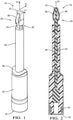
- the stator assembly 16 has an elongated shape extending along a main axis X1 between a bottom flat face 18 transverse to the axis X1 to a head end 20 where is arranged the invention of the present disclosure.
- the stator assembly 16 used as an illustration to the disclosure comprises an annular solenoid 22 wound around a core and arranged in the vicinity to the bottom face 18, two electrical leads 24, 26 upwardly extending from the solenoid 22 toward the head end 20 where each of the leads 24, 26 is provided with a blade terminal 28, 30 that is a sprung terminal having a curved shape forming a leaf spring that can be compresses in a transverse direction to the main axis X1 for enabling resilient deflexions of the blades.
- the solenoid, core and leads are integrally overmoulded forming a large cylindrical body 32 upwardly extending from the bottom face 18 to a transverse shoulder face 36 and, a thin cylindrical body 34 upwardly extending from said shoulder face 36 to the head end 20.
- the large body 32 are overmoulded the solenoid, the core and the connections to the electrical leads and, in the thin body 34 are overmoulded the two leads 24, 26.
- the terminals 28, 30 protrude at the top of said thin body 34.
- a flat partition wall 37 is integrally overmoulded with the thin body 34 and it extends between the blade terminals 28, 30 that are symmetrically arranged on each side of said partition wall 37.
- the leads protrude from the end of the thin body 34 already under the form of flat blades following a face of the wall 37.
- a spring is formed at the very end of each blade by forming a curved portion lifting away from the wall 37 then coming back to the wall, the end of each blade being able to slide against said face of the wall 37.
- the curved portions are distant from each other by an inter-terminals distance D1 and, the wall 37 enables resilient deflexion and flattening of the curved portion while preventing any electrical short between the terminals.
- the two bodies 32, 34 are concentrically formed, both extending about the main axis X1 although, in other embodiments the two bodies may extend about two axes offset from each other.
- an electrical connector 38 At the very top of the fuel injector is arranged an electrical connector 38, represented in figure 3 , provided with two electrical pins 40, 42 adapted to electrically connect to the two blade terminals 28, 30.
- the pins 40, 42 are parallel cylindrical members extending about a connector axis X2, the pins 40, 42 being distant from each other by an inter-pin distance D2 that is smaller than the inter-terminals distance D1.
- said the connector axis X2 is perpendicular to the main axis XI, the injector 10 having a side orientation of the connector and, in a second embodiment represented on figure 5 , the connector axis X2 is aligned with said main axis XI, the injector 10 having a top orientation of the connector.
- the connector 38 is arranged at the top of the injector body 12, the two pins 40, 42 extending above the opening of a bore provided in said body and then, the stator assembly 16 is upwardly inserted in said bore, the thin body 34 with the terminals 28, 30 and the head end 20 engaging first and being inwardly pushed by the large body 32.
- the terminals 28, 30 come in contact with the pins 40, 42 then, further upward displacement of the stator assembly 16 forces the blade terminals 28, 30 to engage between the pins 40, 42 to resiliently deflect and flatten against the partition wall 37 exerting contact forces ensuring electrical contact between said pins and said terminals, thus finally enabling electrical connection from a command unit complementary plugged in said connector 38 to the solenoid.
- the head end 20 perpendicularly engages between the pins 40, 42 and, in the secondary embodiment of figure 5 , the head end 20 is axially aligned with said pins, still engaging between them.
- stator assembly 16 is further provided with a positioning feature 44, also known worldwide by the Japanese name "poka-yoke", arranged in the head end 20 beside the terminals 28, 30.
- said positioning feature 44 is integrally moulded with the stator assembly 16.
- said alignment feature can be a separate feature arranged on the stator assembly.
- the alignment feature 44 represented in figures 6 and 7 in a tri-axes referential system comprising the main axis XI, a perpendicular second axis Y1 extending along the partition wall between the blade terminals and, a transverse third axis Z1 perpendicular to both other axes XI, Y1 comprises a first member 46, particularly used for the perpendicular assembly of the first embodiment of figure 4 and, a second member 54 used for the aligned assembly of the second embodiment of figure 5 .
- the first member 46 is a planar member laterally extensions on both sides of an end the partition wall 37.
- Said first member 46 defines a peripheral rectangular top face 48 with main length L48 extending along the transverse axis Zl, from the distant edges of which downwardly extend along the main axis XI, two rectangular opposed lateral faces 50, 52 mainly extending along the main axis X1.
- the length L48 of the front face is just smaller than the inter-pin distance D2 and, as visible on the top view of figure 8 , the partition wall 37 and the first member 46 have together a "T" cross-section where the vertical leg of the T is the partition wall 37 and the horizontal upper bar of the T is said first member 46 of the positioning feature 44.
- Figure 4 represents a correct positioning of the stator assembly 16, the first member 46 being entirely engaged between the pins 40, 42 and being substantially perpendicular to the connector axis X2. Incorrect positioning, as shown in figure 9 , is prevented by the first member 46 since if not correctly oriented when approaching the end of the upward insertion of the stator assembly 16, the front face 48 would first hit the pins 40, 42 and would stop further engagement forbidding the final insertion of the terminals 28, 30 between the pins 40, 42. Moreover, when the upward insertion is completed as shown on figure 4 , angular rotation of the stator assembly 16 about the main axis X1 is also prevented by the lateral faces 50, 52 that would first hit the pins. Therefore, the first member 46 ensures a good electrical connection of the terminals and the pins in the case of a perpendicular embodiment as shown in figure 4 .
- the alignment feature could be provided with a second first member arranged at the opposite end of the partition wall, changing the cross-section from a T to a symmetrical shape with upper and lower horizontal bars.
- the alignment feature 44 further comprises the second member 54, particularly used for the aligned assembly of the second embodiment of figure 5 , said second member 54 being arranged right below the first member 44 and being integrally moulded as well.
- the second member 54 and the first member 44 join together via a plurality of shoulder faces 56, represented flat or bevelled on the figures.
- the second member 54 is an upward extension of the thin cylindrical body 34 further provided with two diametrically opposed notches 58, 60, defining opposed side walls 62 between which the blade terminal 28, 30 upwardly extends and allow for the curved portion to lift from the partition wall 37.
- said second member 54 is distant from the top end of the thin body 34, wherefrom upwardly extend the partition wall 37 and the blade terminals 28, 30 thus, defining an annular groove 64 surrounding said partition wall 37 and the two blades.
- the second member 54 being arranged below the first member 46 does not interfere, and plays no role in the perpendicular first embodiment of figure 4 , said second member 54 remaining below the pins and not contacting them.
- the second member 54 prevents from incorrect angular orientation of the stator assembly 16 as shown in figure 10 , by guiding the pins into the notches 58, 60 or, more precisely, by engaging the notches around the pins. If not correctly oriented when approaching the end of the upward insertion during assembly of the stator assembly 16, the shoulder faces 56 would first hit the extremity of the pins 40, 42 and would stop further the insertion. Moreover, when the upward insertion is completed as shown on figure 5 , the pins 40, 42 are engaged in the notches 58, 60 between the side faces 62.
- the second member 54 ensures a good electrical connection of the terminals and the pins in the case of a aligned embodiment.
- the positioning feature comprises only one first member 46 and, the second member 54 comprises two opposed halves, one of them being moulded below the first member 46, the other being moulded on the other side of the partition wall where there is no first member.
- Said second half of the second member therefore defines a semi-circular flat upward face that can be considered similarly to a joining shoulder face 56.
- the positioning feature 44 could only comprise one first member 46 and only one half of the second member, this still accommodating both the perpendicular and the aligned arrangements.
- the described positioning feature 44 comprises two distinct members 46, 54.
Landscapes
- Engineering & Computer Science (AREA)
- Chemical & Material Sciences (AREA)
- Combustion & Propulsion (AREA)
- Mechanical Engineering (AREA)
- General Engineering & Computer Science (AREA)
- Physics & Mathematics (AREA)
- Electromagnetism (AREA)
- Manufacturing & Machinery (AREA)
- Fuel-Injection Apparatus (AREA)
Claims (8)
- Statoranordnung (16) eines Kraftstoffinjektors (10), wobei die Statoranordnung elektrische Leitungen und ein Positionierungsmerkmal (44) umfasst,wobei die elektrischen Leitungen zwei Flachflügelklemmen (28, 30), die aus dem Ende eines zylindrischen Körpers (34) hervorstehen, der sich selbst entlang einer Hauptachse (X1) erstreckt, und eine Flachtrennwand (37) aufweisen, die mit dem Körper (34) einstückig ist, wobei sich die Trennwand zwischen den Flügeln erstreckt, die auf jeder Seite der Trennwand (37) symmetrisch eingerichtet sind, wobei die zwei Klemmen (28, 30) angepasst sind, um um die Hauptachse (X1) herum zwei Stifte (40, 42) eines Verbinders (38) in elektrischer Berührung in Eingriff zu nehmen, wobei die zwei Stifte (40, 42) durch einen Abstand (D2) zwischen den Stiften getrennt sind;dadurch gekennzeichnet, dassdas Positionierungsmerkmal (44), das eine inkorrekte Positionierung der Klemmen relativ zu den Stiften verhindert, ein erstes ebenes Element (46) umfasst, das mit der Trennwand (37) einstückig ist und sich auf beiden Seiten der Trennwand (37) lateral erstreckt, wobei die Trennwand (37) und das ebene Element (46) zusammen einen "T"-Querschnitt aufweisen, wobei der vertikale Schenkel des T die Trennwand (37) ist und der horizontale obere Balken des T ein erstes Element (46) des Positionierungsmerkmals (44) ist,wobei das erste Element (46) eine transversale Vorderfläche (48) aufweist, deren Länge (L48), die sich senkrecht zu der Hauptachse (X1) erstreckt, kleiner als der Abstand zwischen den Stiften (D2) ist, so dass während des Eingriffsvorgangs mit dem Verbinder (38), der seine Stifte als sich im Wesentlichen senkrecht zu der Hauptachse (X1) erstreckend aufweist, eine inkorrekte Winkelausrichtung der Statoranordnung (16) durch die Vorderfläche (48) verhindert wird und eine korrekte Winkelausrichtung durch den Eingriff des ersten Elements (46) zwischen den Stiften sichergestellt wird;wobei das Positionierungsmerkmal (44) ferner ein zweites Element (54) umfasst, das um die Leitungen herum eingerichtet ist und axiale Seitenflächen (62) definiert, so dass während des Eingriffsvorgangs mit einem Verbinder (38), der die Stifte als sich an der Hauptachse (X1) ausgerichtet erstreckend aufweist, eine korrekte Winkelausrichtung der Statoranordnung (16) durch den Eingriff jedes Stifts neben einer Seitenfläche (62) sichergestellt wird.
- Statoranordnung (16) nach Anspruch 1, wobei das erste Element (46) ferner zwei sich axial (X1) erstreckende Lateralflächen (50, 52) definiert, die jeweils ein Ende der Vorderfläche (48) verbinden, so dass
eine feinere Einstellung der Winkelausrichtung der Statoranordnung (16) durch die Lateralflächen (50, 52) bereitgestellt wird, die die Stifte berühren und daher eine weitere Drehung der Statoranordnung (16) verhindern. - Statoranordnung (16) nach einem der Ansprüche 1 oder 2, wobei das zweite Element (54) zwei Kerben (58, 60) definiert, in die die Stifte eingreifen, wenn sie korrekt ausgerichtet sind, wobei die Seitenflächen (62) Flächen der Kerben sind.
- Statoranordnung (16) nach Anspruch 3, wobei das erste (46) und das zweite Element (54) einstückig miteinander geformt sind.
- Statoranordnung (16) nach einem der vorhergehenden Ansprüche, wobei das Positionierungsmerkmal (44) einstückig mit der Statoranordnung (16) geformt ist.
- Statoranordnung (16) nach Anspruch 5, wobei die Klemmen (28, 30) federnde Flügel sind, die angepasst sind, um sich elastisch zu verbiegen, wenn sie in Berührung mit den zylindrischen Stiften (40, 42) des Verbinders gezwungen werden, wobei eine zufällige Berührung zwischen den federnden Klemmen durch eine isolierende Trennwand (37) verhindert wird, die zwischen den federnden Klemmen eingerichtet ist, wobei die Wand (37) einstückig mit dem zylindrischen Körper (34) ist.
- Statoranordnung (16) nach Anspruch 6, die ein Positionierungsmerkmal (44) nach einem der Ansprüche 1 bis 4 aufweist, wobei das erste Element (46) des Positionierungsmerkmals (44) senkrecht zu der Trennwand (37) ist.
- Kraftstoffinjektor (10), der einen Körper, der mit einer Bohrung versehen ist, und einen elektrischen Verbinder (38) aufweist, der mit zwei zylindrischen Stiften (40, 42) versehen ist, die sich in die Bohrung erstrecken, und wobei
der Kraftstoffinjektor (10) ferner mit einer Statoranordnung (16) versehen ist, die in der Bohrung eingerichtet ist, wobei die Statoranordnung (16) einem der Ansprüche 5 bis 7 entspricht, wobei die Klemmen (28, 30) der Statoranordnung in elektrischer Berührung mit den Stiften (40, 42) des Verbinders stehen.
Applications Claiming Priority (2)
| Application Number | Priority Date | Filing Date | Title |
|---|---|---|---|
| GB1617942.6A GB2555404B (en) | 2016-10-24 | 2016-10-24 | Positioning feature of a stator assembly of a fuel injector |
| PCT/EP2017/076738 WO2018077721A1 (en) | 2016-10-24 | 2017-10-19 | Positioning feature of a stator assembly of a fuel injector |
Publications (2)
| Publication Number | Publication Date |
|---|---|
| EP3529484A1 EP3529484A1 (de) | 2019-08-28 |
| EP3529484B1 true EP3529484B1 (de) | 2022-02-23 |
Family
ID=57738227
Family Applications (1)
| Application Number | Title | Priority Date | Filing Date |
|---|---|---|---|
| EP17786923.7A Active EP3529484B1 (de) | 2016-10-24 | 2017-10-19 | Statoranordnung eines kraftstoffinjektors mit einer positionierungsvorrichtung |
Country Status (5)
| Country | Link |
|---|---|
| US (1) | US11053899B2 (de) |
| EP (1) | EP3529484B1 (de) |
| CN (1) | CN109964024B (de) |
| GB (1) | GB2555404B (de) |
| WO (1) | WO2018077721A1 (de) |
Family Cites Families (11)
| Publication number | Priority date | Publication date | Assignee | Title |
|---|---|---|---|---|
| DE3220090A1 (de) * | 1982-05-28 | 1983-12-01 | Robert Bosch Gmbh, 7000 Stuttgart | Vorrichtung zur elektrischen kontaktierung eines elektromagnetisch betaetigbaren kraftstoffeinspritzventiles |
| US5129834A (en) | 1991-03-04 | 1992-07-14 | Siemens Automotive L.P. | Multiple function electrical connector for connecting to a fuel-rail-mounted fuel injector |
| JPH1187011A (ja) * | 1997-09-03 | 1999-03-30 | Yazaki Corp | コネクタの成形方法 |
| ATE414994T1 (de) | 2005-02-03 | 2008-12-15 | Delphi Tech Inc | Piezoelektrischer aktor |
| DE102005039548A1 (de) * | 2005-08-22 | 2007-03-01 | Robert Bosch Gmbh | Piezoaktor mit einer Steckverbindung |
| DE102007029968A1 (de) * | 2007-06-28 | 2009-01-08 | Robert Bosch Gmbh | Elektrischer Steckverbinder als Kraftstoffinjektor-Kontakt für schüttelfeste Anwendungen |
| US8047183B2 (en) * | 2009-05-29 | 2011-11-01 | Cummins Intellectual Properties, Inc. | Fuel injector, clamping assembly and method of mounting a fuel injector |
| DE102010031277A1 (de) | 2010-07-13 | 2012-01-19 | Robert Bosch Gmbh | Kraftstoffeinspritzventil mit reduzierter Bauteileanzahl |
| DE102013201897A1 (de) * | 2013-02-06 | 2014-08-07 | Robert Bosch Gmbh | Ventil zum Zumessen von Fluid |
| GB201309126D0 (en) * | 2013-05-21 | 2013-07-03 | Delphi Tech Holding Sarl | Fuel Injector |
| US10234441B2 (en) * | 2016-09-16 | 2019-03-19 | Sogefi Engine Systems Usa, Inc. | Water in fuel (WIF) sensor having electrostatic discharge capability |
-
2016
- 2016-10-24 GB GB1617942.6A patent/GB2555404B/en active Active
-
2017
- 2017-10-19 CN CN201780071812.7A patent/CN109964024B/zh active Active
- 2017-10-19 WO PCT/EP2017/076738 patent/WO2018077721A1/en not_active Ceased
- 2017-10-19 US US16/344,570 patent/US11053899B2/en active Active
- 2017-10-19 EP EP17786923.7A patent/EP3529484B1/de active Active
Also Published As
| Publication number | Publication date |
|---|---|
| US11053899B2 (en) | 2021-07-06 |
| EP3529484A1 (de) | 2019-08-28 |
| GB2555404A (en) | 2018-05-02 |
| CN109964024B (zh) | 2021-09-14 |
| WO2018077721A1 (en) | 2018-05-03 |
| US20200018275A1 (en) | 2020-01-16 |
| CN109964024A (zh) | 2019-07-02 |
| GB2555404B (en) | 2019-04-17 |
| GB201617942D0 (en) | 2016-12-07 |
Similar Documents
| Publication | Publication Date | Title |
|---|---|---|
| US6705292B2 (en) | Apparatus and method of connecting a fuel injector and a fuel rail | |
| US9118130B1 (en) | Low insertion force terminal | |
| EP2941559B1 (de) | Kraftstoffeinspritzanordnung | |
| US7445001B2 (en) | Coil-on-plug ignition terminal | |
| EP2999874B1 (de) | Kraftstoffeinspritzventil | |
| US9759172B2 (en) | Fuel injector having a reduced number of components | |
| EP3529484B1 (de) | Statoranordnung eines kraftstoffinjektors mit einer positionierungsvorrichtung | |
| JP2006004840A (ja) | 中継コネクタと電気部品との接続構造 | |
| US20180372042A1 (en) | Long Injector For Fuel Injection Into An Internal Combustion Engine | |
| CN204941756U (zh) | 电连接器以及使用其的燃料喷射器 | |
| US6994559B1 (en) | Device for the electrical connection of contact pins to connecting pins of a plug-in connector formed from the device | |
| US9819108B2 (en) | Electrical connector for a fuel injector having a terminal with a twisted intermediate section | |
| KR20120070721A (ko) | 터미널 및 이를 사용한 커넥터 | |
| US6981662B2 (en) | Coupling device assembly | |
| EP2299101B1 (de) | Magnetventil mit direkt kontaktierter Steuereinheit | |
| US20110244736A1 (en) | Female electrical contact pin | |
| JP6318866B2 (ja) | 燃料噴射弁 | |
| US8690610B2 (en) | Joint connector with a plurality of terminals, a housing, and a spring | |
| US20230087659A1 (en) | Wire to wire junction connector | |
| JP2019185961A (ja) | Bncコネクタプラグ及びbncコネクタ | |
| EP3657007B1 (de) | Kraftstoffinjektor mit einem positionierstift, brennkraftmaschine mit verwendung davon und verfahren | |
| JP2010121584A (ja) | インジェクタ | |
| EP1780402A1 (de) | Verbindungsstück, Verbindungsstück-Aktor-Einheit, Einspritzventil und Verfahren zum Zusammenbau des Aktors in das Einspritzventil | |
| WO2017144313A1 (en) | Fuel injector | |
| WO2018146246A1 (en) | Fuel injector |
Legal Events
| Date | Code | Title | Description |
|---|---|---|---|
| STAA | Information on the status of an ep patent application or granted ep patent |
Free format text: STATUS: UNKNOWN |
|
| STAA | Information on the status of an ep patent application or granted ep patent |
Free format text: STATUS: THE INTERNATIONAL PUBLICATION HAS BEEN MADE |
|
| PUAI | Public reference made under article 153(3) epc to a published international application that has entered the european phase |
Free format text: ORIGINAL CODE: 0009012 |
|
| STAA | Information on the status of an ep patent application or granted ep patent |
Free format text: STATUS: REQUEST FOR EXAMINATION WAS MADE |
|
| 17P | Request for examination filed |
Effective date: 20190524 |
|
| AK | Designated contracting states |
Kind code of ref document: A1 Designated state(s): AL AT BE BG CH CY CZ DE DK EE ES FI FR GB GR HR HU IE IS IT LI LT LU LV MC MK MT NL NO PL PT RO RS SE SI SK SM TR |
|
| STAA | Information on the status of an ep patent application or granted ep patent |
Free format text: STATUS: EXAMINATION IS IN PROGRESS |
|
| 17Q | First examination report despatched |
Effective date: 20201211 |
|
| GRAP | Despatch of communication of intention to grant a patent |
Free format text: ORIGINAL CODE: EPIDOSNIGR1 |
|
| STAA | Information on the status of an ep patent application or granted ep patent |
Free format text: STATUS: GRANT OF PATENT IS INTENDED |
|
| INTG | Intention to grant announced |
Effective date: 20210917 |
|
| GRAS | Grant fee paid |
Free format text: ORIGINAL CODE: EPIDOSNIGR3 |
|
| GRAA | (expected) grant |
Free format text: ORIGINAL CODE: 0009210 |
|
| STAA | Information on the status of an ep patent application or granted ep patent |
Free format text: STATUS: THE PATENT HAS BEEN GRANTED |
|
| AK | Designated contracting states |
Kind code of ref document: B1 Designated state(s): AL AT BE BG CH CY CZ DE DK EE ES FI FR GB GR HR HU IE IS IT LI LT LU LV MC MK MT NL NO PL PT RO RS SE SI SK SM TR |
|
| REG | Reference to a national code |
Ref country code: GB Ref legal event code: FG4D |
|
| REG | Reference to a national code |
Ref country code: CH Ref legal event code: EP |
|
| REG | Reference to a national code |
Ref country code: AT Ref legal event code: REF Ref document number: 1470642 Country of ref document: AT Kind code of ref document: T Effective date: 20220315 |
|
| REG | Reference to a national code |
Ref country code: IE Ref legal event code: FG4D |
|
| REG | Reference to a national code |
Ref country code: DE Ref legal event code: R096 Ref document number: 602017053753 Country of ref document: DE |
|
| REG | Reference to a national code |
Ref country code: DE Ref legal event code: R081 Ref document number: 602017053753 Country of ref document: DE Owner name: DELPHI TECHNOLOGIES IP LIMITED, BB Free format text: FORMER OWNER: DELPHI TECHNOLOGIES IP LIMITED, SAINT MICHAEL, BB Ref country code: DE Ref legal event code: R081 Ref document number: 602017053753 Country of ref document: DE Owner name: PHINIA DELPHI LUXEMBOURG SARL, LU Free format text: FORMER OWNER: DELPHI TECHNOLOGIES IP LIMITED, SAINT MICHAEL, BB |
|
| RAP4 | Party data changed (patent owner data changed or rights of a patent transferred) |
Owner name: DELPHI TECHNOLOGIES IP LIMITED |
|
| REG | Reference to a national code |
Ref country code: LT Ref legal event code: MG9D |
|
| REG | Reference to a national code |
Ref country code: NL Ref legal event code: MP Effective date: 20220223 |
|
| REG | Reference to a national code |
Ref country code: AT Ref legal event code: MK05 Ref document number: 1470642 Country of ref document: AT Kind code of ref document: T Effective date: 20220223 |
|
| PG25 | Lapsed in a contracting state [announced via postgrant information from national office to epo] |
Ref country code: SE Free format text: LAPSE BECAUSE OF FAILURE TO SUBMIT A TRANSLATION OF THE DESCRIPTION OR TO PAY THE FEE WITHIN THE PRESCRIBED TIME-LIMIT Effective date: 20220223 Ref country code: RS Free format text: LAPSE BECAUSE OF FAILURE TO SUBMIT A TRANSLATION OF THE DESCRIPTION OR TO PAY THE FEE WITHIN THE PRESCRIBED TIME-LIMIT Effective date: 20220223 Ref country code: PT Free format text: LAPSE BECAUSE OF FAILURE TO SUBMIT A TRANSLATION OF THE DESCRIPTION OR TO PAY THE FEE WITHIN THE PRESCRIBED TIME-LIMIT Effective date: 20220623 Ref country code: NO Free format text: LAPSE BECAUSE OF FAILURE TO SUBMIT A TRANSLATION OF THE DESCRIPTION OR TO PAY THE FEE WITHIN THE PRESCRIBED TIME-LIMIT Effective date: 20220523 Ref country code: NL Free format text: LAPSE BECAUSE OF FAILURE TO SUBMIT A TRANSLATION OF THE DESCRIPTION OR TO PAY THE FEE WITHIN THE PRESCRIBED TIME-LIMIT Effective date: 20220223 Ref country code: LT Free format text: LAPSE BECAUSE OF FAILURE TO SUBMIT A TRANSLATION OF THE DESCRIPTION OR TO PAY THE FEE WITHIN THE PRESCRIBED TIME-LIMIT Effective date: 20220223 Ref country code: HR Free format text: LAPSE BECAUSE OF FAILURE TO SUBMIT A TRANSLATION OF THE DESCRIPTION OR TO PAY THE FEE WITHIN THE PRESCRIBED TIME-LIMIT Effective date: 20220223 Ref country code: ES Free format text: LAPSE BECAUSE OF FAILURE TO SUBMIT A TRANSLATION OF THE DESCRIPTION OR TO PAY THE FEE WITHIN THE PRESCRIBED TIME-LIMIT Effective date: 20220223 Ref country code: BG Free format text: LAPSE BECAUSE OF FAILURE TO SUBMIT A TRANSLATION OF THE DESCRIPTION OR TO PAY THE FEE WITHIN THE PRESCRIBED TIME-LIMIT Effective date: 20220523 |
|
| PG25 | Lapsed in a contracting state [announced via postgrant information from national office to epo] |
Ref country code: PL Free format text: LAPSE BECAUSE OF FAILURE TO SUBMIT A TRANSLATION OF THE DESCRIPTION OR TO PAY THE FEE WITHIN THE PRESCRIBED TIME-LIMIT Effective date: 20220223 Ref country code: LV Free format text: LAPSE BECAUSE OF FAILURE TO SUBMIT A TRANSLATION OF THE DESCRIPTION OR TO PAY THE FEE WITHIN THE PRESCRIBED TIME-LIMIT Effective date: 20220223 Ref country code: GR Free format text: LAPSE BECAUSE OF FAILURE TO SUBMIT A TRANSLATION OF THE DESCRIPTION OR TO PAY THE FEE WITHIN THE PRESCRIBED TIME-LIMIT Effective date: 20220524 Ref country code: FI Free format text: LAPSE BECAUSE OF FAILURE TO SUBMIT A TRANSLATION OF THE DESCRIPTION OR TO PAY THE FEE WITHIN THE PRESCRIBED TIME-LIMIT Effective date: 20220223 Ref country code: AT Free format text: LAPSE BECAUSE OF FAILURE TO SUBMIT A TRANSLATION OF THE DESCRIPTION OR TO PAY THE FEE WITHIN THE PRESCRIBED TIME-LIMIT Effective date: 20220223 |
|
| PG25 | Lapsed in a contracting state [announced via postgrant information from national office to epo] |
Ref country code: IS Free format text: LAPSE BECAUSE OF FAILURE TO SUBMIT A TRANSLATION OF THE DESCRIPTION OR TO PAY THE FEE WITHIN THE PRESCRIBED TIME-LIMIT Effective date: 20220623 |
|
| PG25 | Lapsed in a contracting state [announced via postgrant information from national office to epo] |
Ref country code: SM Free format text: LAPSE BECAUSE OF FAILURE TO SUBMIT A TRANSLATION OF THE DESCRIPTION OR TO PAY THE FEE WITHIN THE PRESCRIBED TIME-LIMIT Effective date: 20220223 Ref country code: SK Free format text: LAPSE BECAUSE OF FAILURE TO SUBMIT A TRANSLATION OF THE DESCRIPTION OR TO PAY THE FEE WITHIN THE PRESCRIBED TIME-LIMIT Effective date: 20220223 Ref country code: RO Free format text: LAPSE BECAUSE OF FAILURE TO SUBMIT A TRANSLATION OF THE DESCRIPTION OR TO PAY THE FEE WITHIN THE PRESCRIBED TIME-LIMIT Effective date: 20220223 Ref country code: EE Free format text: LAPSE BECAUSE OF FAILURE TO SUBMIT A TRANSLATION OF THE DESCRIPTION OR TO PAY THE FEE WITHIN THE PRESCRIBED TIME-LIMIT Effective date: 20220223 Ref country code: DK Free format text: LAPSE BECAUSE OF FAILURE TO SUBMIT A TRANSLATION OF THE DESCRIPTION OR TO PAY THE FEE WITHIN THE PRESCRIBED TIME-LIMIT Effective date: 20220223 Ref country code: CZ Free format text: LAPSE BECAUSE OF FAILURE TO SUBMIT A TRANSLATION OF THE DESCRIPTION OR TO PAY THE FEE WITHIN THE PRESCRIBED TIME-LIMIT Effective date: 20220223 |
|
| REG | Reference to a national code |
Ref country code: DE Ref legal event code: R097 Ref document number: 602017053753 Country of ref document: DE |
|
| PG25 | Lapsed in a contracting state [announced via postgrant information from national office to epo] |
Ref country code: AL Free format text: LAPSE BECAUSE OF FAILURE TO SUBMIT A TRANSLATION OF THE DESCRIPTION OR TO PAY THE FEE WITHIN THE PRESCRIBED TIME-LIMIT Effective date: 20220223 |
|
| PLBE | No opposition filed within time limit |
Free format text: ORIGINAL CODE: 0009261 |
|
| STAA | Information on the status of an ep patent application or granted ep patent |
Free format text: STATUS: NO OPPOSITION FILED WITHIN TIME LIMIT |
|
| 26N | No opposition filed |
Effective date: 20221124 |
|
| PG25 | Lapsed in a contracting state [announced via postgrant information from national office to epo] |
Ref country code: SI Free format text: LAPSE BECAUSE OF FAILURE TO SUBMIT A TRANSLATION OF THE DESCRIPTION OR TO PAY THE FEE WITHIN THE PRESCRIBED TIME-LIMIT Effective date: 20220223 |
|
| PG25 | Lapsed in a contracting state [announced via postgrant information from national office to epo] |
Ref country code: MC Free format text: LAPSE BECAUSE OF FAILURE TO SUBMIT A TRANSLATION OF THE DESCRIPTION OR TO PAY THE FEE WITHIN THE PRESCRIBED TIME-LIMIT Effective date: 20220223 |
|
| REG | Reference to a national code |
Ref country code: CH Ref legal event code: PL |
|
| P01 | Opt-out of the competence of the unified patent court (upc) registered |
Effective date: 20230327 |
|
| REG | Reference to a national code |
Ref country code: BE Ref legal event code: MM Effective date: 20221031 |
|
| PG25 | Lapsed in a contracting state [announced via postgrant information from national office to epo] |
Ref country code: LU Free format text: LAPSE BECAUSE OF NON-PAYMENT OF DUE FEES Effective date: 20221019 |
|
| PG25 | Lapsed in a contracting state [announced via postgrant information from national office to epo] |
Ref country code: LI Free format text: LAPSE BECAUSE OF NON-PAYMENT OF DUE FEES Effective date: 20221031 Ref country code: IT Free format text: LAPSE BECAUSE OF FAILURE TO SUBMIT A TRANSLATION OF THE DESCRIPTION OR TO PAY THE FEE WITHIN THE PRESCRIBED TIME-LIMIT Effective date: 20220223 Ref country code: CH Free format text: LAPSE BECAUSE OF NON-PAYMENT OF DUE FEES Effective date: 20221031 |
|
| PG25 | Lapsed in a contracting state [announced via postgrant information from national office to epo] |
Ref country code: BE Free format text: LAPSE BECAUSE OF NON-PAYMENT OF DUE FEES Effective date: 20221031 |
|
| PG25 | Lapsed in a contracting state [announced via postgrant information from national office to epo] |
Ref country code: IE Free format text: LAPSE BECAUSE OF NON-PAYMENT OF DUE FEES Effective date: 20221019 |
|
| PG25 | Lapsed in a contracting state [announced via postgrant information from national office to epo] |
Ref country code: HU Free format text: LAPSE BECAUSE OF FAILURE TO SUBMIT A TRANSLATION OF THE DESCRIPTION OR TO PAY THE FEE WITHIN THE PRESCRIBED TIME-LIMIT; INVALID AB INITIO Effective date: 20171019 |
|
| REG | Reference to a national code |
Ref country code: DE Ref legal event code: R081 Ref document number: 602017053753 Country of ref document: DE Owner name: PHINIA DELPHI LUXEMBOURG SARL, LU Free format text: FORMER OWNER: DELPHI TECHNOLOGIES IP LIMITED, ST. MICHAEL, BB |
|
| PG25 | Lapsed in a contracting state [announced via postgrant information from national office to epo] |
Ref country code: CY Free format text: LAPSE BECAUSE OF FAILURE TO SUBMIT A TRANSLATION OF THE DESCRIPTION OR TO PAY THE FEE WITHIN THE PRESCRIBED TIME-LIMIT Effective date: 20220223 |
|
| REG | Reference to a national code |
Ref country code: GB Ref legal event code: 732E Free format text: REGISTERED BETWEEN 20240411 AND 20240417 |
|
| PG25 | Lapsed in a contracting state [announced via postgrant information from national office to epo] |
Ref country code: MK Free format text: LAPSE BECAUSE OF FAILURE TO SUBMIT A TRANSLATION OF THE DESCRIPTION OR TO PAY THE FEE WITHIN THE PRESCRIBED TIME-LIMIT Effective date: 20220223 |
|
| PG25 | Lapsed in a contracting state [announced via postgrant information from national office to epo] |
Ref country code: MT Free format text: LAPSE BECAUSE OF FAILURE TO SUBMIT A TRANSLATION OF THE DESCRIPTION OR TO PAY THE FEE WITHIN THE PRESCRIBED TIME-LIMIT Effective date: 20220223 |
|
| PGFP | Annual fee paid to national office [announced via postgrant information from national office to epo] |
Ref country code: GB Payment date: 20250911 Year of fee payment: 9 |
|
| PGFP | Annual fee paid to national office [announced via postgrant information from national office to epo] |
Ref country code: FR Payment date: 20250912 Year of fee payment: 9 |
|
| PG25 | Lapsed in a contracting state [announced via postgrant information from national office to epo] |
Ref country code: TR Free format text: LAPSE BECAUSE OF FAILURE TO SUBMIT A TRANSLATION OF THE DESCRIPTION OR TO PAY THE FEE WITHIN THE PRESCRIBED TIME-LIMIT Effective date: 20220223 |
|
| PGFP | Annual fee paid to national office [announced via postgrant information from national office to epo] |
Ref country code: DE Payment date: 20250912 Year of fee payment: 9 |