EP3529115B1 - Magnetventil zur steuerung des bremsdrucks einer radbremse - Google Patents
Magnetventil zur steuerung des bremsdrucks einer radbremse Download PDFInfo
- Publication number
- EP3529115B1 EP3529115B1 EP17780650.2A EP17780650A EP3529115B1 EP 3529115 B1 EP3529115 B1 EP 3529115B1 EP 17780650 A EP17780650 A EP 17780650A EP 3529115 B1 EP3529115 B1 EP 3529115B1
- Authority
- EP
- European Patent Office
- Prior art keywords
- valve element
- valve
- contact surface
- armature
- solenoid valve
- Prior art date
- Legal status (The legal status is an assumption and is not a legal conclusion. Google has not performed a legal analysis and makes no representation as to the accuracy of the status listed.)
- Active
Links
Images



Classifications
-
- B—PERFORMING OPERATIONS; TRANSPORTING
- B60—VEHICLES IN GENERAL
- B60T—VEHICLE BRAKE CONTROL SYSTEMS OR PARTS THEREOF; BRAKE CONTROL SYSTEMS OR PARTS THEREOF, IN GENERAL; ARRANGEMENT OF BRAKING ELEMENTS ON VEHICLES IN GENERAL; PORTABLE DEVICES FOR PREVENTING UNWANTED MOVEMENT OF VEHICLES; VEHICLE MODIFICATIONS TO FACILITATE COOLING OF BRAKES
- B60T13/00—Transmitting braking action from initiating means to ultimate brake actuator with power assistance or drive; Brake systems incorporating such transmitting means, e.g. air-pressure brake systems
- B60T13/10—Transmitting braking action from initiating means to ultimate brake actuator with power assistance or drive; Brake systems incorporating such transmitting means, e.g. air-pressure brake systems with fluid assistance, drive, or release
- B60T13/66—Electrical control in fluid-pressure brake systems
- B60T13/68—Electrical control in fluid-pressure brake systems by electrically-controlled valves
- B60T13/686—Electrical control in fluid-pressure brake systems by electrically-controlled valves in hydraulic systems or parts thereof
-
- B—PERFORMING OPERATIONS; TRANSPORTING
- B60—VEHICLES IN GENERAL
- B60T—VEHICLE BRAKE CONTROL SYSTEMS OR PARTS THEREOF; BRAKE CONTROL SYSTEMS OR PARTS THEREOF, IN GENERAL; ARRANGEMENT OF BRAKING ELEMENTS ON VEHICLES IN GENERAL; PORTABLE DEVICES FOR PREVENTING UNWANTED MOVEMENT OF VEHICLES; VEHICLE MODIFICATIONS TO FACILITATE COOLING OF BRAKES
- B60T15/00—Construction arrangement, or operation of valves incorporated in power brake systems and not covered by groups B60T11/00 or B60T13/00
- B60T15/02—Application and release valves
- B60T15/025—Electrically controlled valves
- B60T15/028—Electrically controlled valves in hydraulic systems
-
- B—PERFORMING OPERATIONS; TRANSPORTING
- B60—VEHICLES IN GENERAL
- B60T—VEHICLE BRAKE CONTROL SYSTEMS OR PARTS THEREOF; BRAKE CONTROL SYSTEMS OR PARTS THEREOF, IN GENERAL; ARRANGEMENT OF BRAKING ELEMENTS ON VEHICLES IN GENERAL; PORTABLE DEVICES FOR PREVENTING UNWANTED MOVEMENT OF VEHICLES; VEHICLE MODIFICATIONS TO FACILITATE COOLING OF BRAKES
- B60T8/00—Arrangements for adjusting wheel-braking force to meet varying vehicular or ground-surface conditions, e.g. limiting or varying distribution of braking force
- B60T8/32—Arrangements for adjusting wheel-braking force to meet varying vehicular or ground-surface conditions, e.g. limiting or varying distribution of braking force responsive to a speed condition, e.g. acceleration or deceleration
- B60T8/34—Arrangements for adjusting wheel-braking force to meet varying vehicular or ground-surface conditions, e.g. limiting or varying distribution of braking force responsive to a speed condition, e.g. acceleration or deceleration having a fluid pressure regulator responsive to a speed condition
- B60T8/341—Systems characterised by their valves
-
- B—PERFORMING OPERATIONS; TRANSPORTING
- B60—VEHICLES IN GENERAL
- B60T—VEHICLE BRAKE CONTROL SYSTEMS OR PARTS THEREOF; BRAKE CONTROL SYSTEMS OR PARTS THEREOF, IN GENERAL; ARRANGEMENT OF BRAKING ELEMENTS ON VEHICLES IN GENERAL; PORTABLE DEVICES FOR PREVENTING UNWANTED MOVEMENT OF VEHICLES; VEHICLE MODIFICATIONS TO FACILITATE COOLING OF BRAKES
- B60T8/00—Arrangements for adjusting wheel-braking force to meet varying vehicular or ground-surface conditions, e.g. limiting or varying distribution of braking force
- B60T8/32—Arrangements for adjusting wheel-braking force to meet varying vehicular or ground-surface conditions, e.g. limiting or varying distribution of braking force responsive to a speed condition, e.g. acceleration or deceleration
- B60T8/34—Arrangements for adjusting wheel-braking force to meet varying vehicular or ground-surface conditions, e.g. limiting or varying distribution of braking force responsive to a speed condition, e.g. acceleration or deceleration having a fluid pressure regulator responsive to a speed condition
- B60T8/36—Arrangements for adjusting wheel-braking force to meet varying vehicular or ground-surface conditions, e.g. limiting or varying distribution of braking force responsive to a speed condition, e.g. acceleration or deceleration having a fluid pressure regulator responsive to a speed condition including a pilot valve responding to an electromagnetic force
- B60T8/3615—Electromagnetic valves specially adapted for anti-lock brake and traction control systems
- B60T8/363—Electromagnetic valves specially adapted for anti-lock brake and traction control systems in hydraulic systems
-
- F—MECHANICAL ENGINEERING; LIGHTING; HEATING; WEAPONS; BLASTING
- F16—ENGINEERING ELEMENTS AND UNITS; GENERAL MEASURES FOR PRODUCING AND MAINTAINING EFFECTIVE FUNCTIONING OF MACHINES OR INSTALLATIONS; THERMAL INSULATION IN GENERAL
- F16K—VALVES; TAPS; COCKS; ACTUATING-FLOATS; DEVICES FOR VENTING OR AERATING
- F16K31/00—Actuating devices; Operating means; Releasing devices
- F16K31/02—Actuating devices; Operating means; Releasing devices electric; magnetic
- F16K31/06—Actuating devices; Operating means; Releasing devices electric; magnetic using a magnet, e.g. diaphragm valves, cutting off by means of a liquid
- F16K31/0644—One-way valve
- F16K31/0651—One-way valve the fluid passing through the solenoid coil
-
- G—PHYSICS
- G05—CONTROLLING; REGULATING
- G05D—SYSTEMS FOR CONTROLLING OR REGULATING NON-ELECTRIC VARIABLES
- G05D16/00—Control of fluid pressure
- G05D16/20—Control of fluid pressure characterised by the use of electric means
- G05D16/2006—Control of fluid pressure characterised by the use of electric means with direct action of electric energy on controlling means
- G05D16/2013—Control of fluid pressure characterised by the use of electric means with direct action of electric energy on controlling means using throttling means as controlling means
- G05D16/2022—Control of fluid pressure characterised by the use of electric means with direct action of electric energy on controlling means using throttling means as controlling means actuated by a proportional solenoid
-
- B—PERFORMING OPERATIONS; TRANSPORTING
- B60—VEHICLES IN GENERAL
- B60T—VEHICLE BRAKE CONTROL SYSTEMS OR PARTS THEREOF; BRAKE CONTROL SYSTEMS OR PARTS THEREOF, IN GENERAL; ARRANGEMENT OF BRAKING ELEMENTS ON VEHICLES IN GENERAL; PORTABLE DEVICES FOR PREVENTING UNWANTED MOVEMENT OF VEHICLES; VEHICLE MODIFICATIONS TO FACILITATE COOLING OF BRAKES
- B60T2270/00—Further aspects of brake control systems not otherwise provided for
- B60T2270/10—ABS control systems
Definitions
- the present invention relates to a solenoid valve for controlling the brake pressure of a wheel brake of a slip-controllable hydraulic brake system of a motor vehicle, with a longitudinally movable at least partially arranged in a valve insert and interacting with a valve seat, which in the installed position of a spring device with a force component acting in the opening direction with respect to the valve seat is acted upon and can be actuated by means of an electromagnetic actuator in the closing direction with respect to the valve seat, wherein the valve element is arranged between an armature and the valve seat and a contact surface is formed on the valve element on which the valve element is in operative connection with the armature, characterized in that that the contact surface is designed such that there is a non-right-angled intersection angle between a central axis of the valve element and the contact surface.
- the patent application for example, is from the prior art DE 10 2007 053 134 A1 known.
- This document relates to a solenoid valve, in particular for a hydraulic unit, which is used, for example, in an anti-lock braking system (ABS) or a traction control system (ASR system) or an electronic stability program system (ESP system).
- ABS anti-lock braking system
- ASR traction control system
- ESP electronic stability program system
- the solenoid valve 1 which is designed, for example, as a normally open control valve, comprises a magnet assembly 3 for generating a magnetic flux, which has a Housing jacket 3.1, a winding support 3.2, a coil winding 3.3 and a cover plate 3.4, and a valve cartridge 2, which comprises a capsule 2.1, a valve insert 8 pushed into the capsule 2.1 with a first end, a magnet armature 4 with a valve element 6 (also called a tappet ) and a return spring 7 comprises.
- the capsule 2.1 and the valve insert 8 of the valve cartridge 2 are pressed together and the valve cartridge 2 is hydraulically sealed off from the atmosphere by a sealing weld 2.2.
- the valve insert 8 absorbs the pressure forces occurring in the hydraulic system and forwards them via a caulking flange 11 to a caulking area 12 of a fluid block 13.
- the magnet assembly 3 generates a magnetic force by energizing the coil winding 3.3 via electrical connections 3.5, which moves the longitudinally movable magnet armature 4 with the valve element 6, which comprises a closing element 6.1 with a main sealing element 6.2, against the force of the return spring 7 against the valve insert 8, whereby the valve element 6 and the return spring 7 are guided in an inner bore of the valve insert 2.
- the valve insert 8 conducts the magnetic flux introduced by the magnet assembly 3 via the cover plate 3.4 axially over an air gap 5 in the direction of the magnet armature 4.
- valve insert 8 receives the so-called valve body 9 at a second end, which comprises a main valve seat 9.1 in which the The main sealing element 6.2, designed as a sealing cap, is immersed in a sealing manner in order to implement the sealing function of the solenoid valve 1.
- a lower valve part 10 which comprises a check valve 10.1 arranged eccentrically to the main valve axis, is placed axially on the valve insert 8 and is supported.
- the lower valve part 10, designed as a plastic insert, for example, also serves to seal against the surrounding fluid block 13, to seal against the valve body 9 and to accommodate a flat filter 10.2.
- valve element At least part of the valve element is arranged in a valve space delimited by the valve insert in the area of the valve seat. Furthermore stands one end of the valve element facing away from the valve chamber in operative connection with an armature.
- an end face of the armature facing the valve insert and / or an end face of the valve insert facing the end faces of the armature is designed with a surface profile such that a flow cross-section limited by the end faces varies at least regionally in the radial direction and / or in the circumferential direction of the armature.
- valve element tapepet
- armature components are installed in the valve without guiding them (i.e. with all degrees of freedom).
- the components are loosely mounted to one another and can therefore have a wide variety of orientations.
- the valve element has a somewhat stronger guidance through the set play than the armature.
- the anchor is often a cold-formed steel component.
- the valve element is an injection-molded part made from fiber-reinforced plastic. The production often takes place with a side injection point.
- the resulting component inaccuracy (especially on the armature, valve element) has a strong influence on the pressure setting accuracy.
- the solenoid valve according to the invention advantageously enables an improvement in the pressure setting accuracy of the inlet valve and an avoidance of undefined changing magnetic forces. This is made possible according to the invention by the features of the independent patent claim. Further developments of the invention are specified in the dependent claims.
- the solenoid valve according to the invention for controlling the brake pressure of a wheel brake of a slip-controllable hydraulic brake system of a motor vehicle, with a longitudinally movable at least partially arranged in a valve insert and interacting with a valve seat, which in the installed position is acted upon by a spring device with a force component acting in the opening direction with respect to the valve seat and by means of an electromagnetic actuator can be actuated in the closing direction with respect to the valve seat, wherein the valve element is arranged between an armature and the valve seat and a contact surface is formed on the valve element, on which the valve element is in operative connection with the armature, characterized in that the contact surface is formed in such a way is that there is a non-right-angled intersection angle between a central axis of the valve element and the contact surface.
- the central axis of the valve element is understood to be a virtual axis which runs through the geometric center of the cross section of the valve element.
- the central axis is parallel to the circumferential surface of the valve element.
- the central axis runs from the main sealing element to the end face facing the armature. It follows a possible curvature of the valve element.
- the contact area is also understood to be a virtual area that delimits the valve element and thereby represents a contact area with the armature when both components are in contact with one another in the installed position. It is defined by means of individual contact points or contact areas.
- the contact surface can also consist of several contact points or several partial contact surfaces.
- the contact surface is generally flat, that is to say two-dimensional.
- the contact surface is therefore to be understood as an inclined virtual plane at the end of the valve element facing the armature, with contact points being located thereon that define a contact situation between the valve element and the armature.
- the intersection angle is understood to be the smallest angle that the central axis forms with the contact surface. According to the invention it is now provided that the resulting contact surface of the Valve element has an angle deviating from a right angle (ie 90 °) to the central axis of the valve element at the level of the end face.
- the valve element is injection molded and in particular fiber-reinforced. As already stated, this leads to a distortion of the valve element.
- an end face of the valve element that is inclined in relation to the direction of movement of the valve element would be formed from this. Because of the loose guidance, the armature would align itself in accordance with this inclined end face of the valve element. This would lead to a tilting of the armature in the event of a movement. This results in a variation in the magnetic force and thus a variation in the pressure setting accuracy. The compensation of the production-related distortion of the component thus enables improved pressure setting accuracy.
- the distortion of the component is not directly compensated, but the effects of the distortion of the valve element (plunger) on the bearing surface for the armature are compensated by a correspondingly changed design of the end face or contact surface, which is the bearing surface for the Represents anchor. Basically, it creates an oblique face with respect to the ram. This "inclined" plane compensates for the distortion (especially of the plunger tip) during injection and thus creates a plunger that is as straight as possible (in relation to the function-relevant tip).
- the expected delay is determined, for example by means of simulation or measurement.
- an adaptation of the design of the valve element in order to take into account the anticipated warpage.
- an inclined contact surface is created at the rear end of the valve element in order to form a non-perpendicular relationship between the central axis and the contact surface.
- the inclined contact surface can be generated by means of defined contact points of different heights.
- an inclined end face or projections can be provided on the end face. The adaptation and formation of the contact surface is therefore carried out by designing the end points of the end face.
- the solenoid valve is characterized in that at least one projection, in particular a plurality of projections, is formed on the end face of the valve element and defines the contact surface.
- the end face has an elevation (for example a step-shaped elevation) by means of which the mentioned (in relation to the valve element) inclined contact surface is formed.
- several projections are provided, i.e. at least two, or for example three or four or five contact points.
- the protrusions are also referred to as pads (or contact pads).
- the protrusions define the points of contact with the anchor.
- the remaining area of the end face is not in contact with the armature even when they are in contact with one another.
- the end face of the valve element can alternatively also have another profile which defines and forms the inclined contact surface.
- An inclined end face itself can also be understood as a projection due to the highlighted area on one side.
- the advantage here is the simple implementation for the formation of the contact surface, which is not at right angles with respect to the central axis of the valve element.
- the positioning of projections on the front side is associated with a low manufacturing cost.
- the tool can be adapted (e.g. by means of a recess) in order to form the projections in the injection molding process.
- the force introduction is evenly distributed.
- the solenoid valve is characterized in that the contact surface has a defined angle to the central axis of the valve element.
- the contact surface formed by the end of the valve element for the armature has a defined, non-right-angled angle.
- a deviation is advantageously in the order of magnitude of 1 °. For example, a deviation of 0.33 ° was found to be advantageous.
- the angle between the central axis and the contact surface is 89.67 ° at the minimum point.
- an accurate setting of the contact surface can advantageously take place. This enables a more precise guidance of the anchor. This in turn reduces tilting of the armature during axial movement by creating a bearing surface that is perpendicular to the direction of movement of the armature.
- the solenoid valve is characterized in that the angle is defined in such a way that the contact surface enables the armature to move in the axial direction without tilting the armature.
- the solenoid valve is characterized in that the angle is defined in such a way that a distortion of the valve element caused by a production process is compensated for by the angle.
- the production process is understood to mean injection molding, preferably with fiber-reinforced plastic.
- compensation reference is made to the statements above.
- This advantageously creates a suitable bearing surface for the armature in order to prevent it from tilting.
- the reproducible warpage effect is used in, for example, fiber-reinforced plastic injection-molded parts with lateral injection depending on the fiber orientation. Compensation for the components produced is thus made possible.
- the solenoid valve is characterized in that the angle is defined in such a way that, in the installed position of the valve element, the contact surface is orthogonal to a direction of movement of the valve element; and / or is orthogonal to a central axis of the solenoid valve.
- the installation position of the valve element is understood to mean the valve element built into the solenoid valve.
- the direction of movement of the valve element runs in the direction of the central axis of the solenoid valve.
- the direction of movement of the armature also runs in the direction of the central axis of the solenoid valve, so that the definition of the angle of the contact surface can also take place as a function of the desired direction of movement of the armature. This advantageously enables suitable guidance of the armature. This makes it possible to avoid tilting the armature during axial movement.
- the solenoid valve is characterized in that the height of the projection is dimensioned such that the defined angle is set as a result.
- the projection (or the projections) are defined accordingly, in particular their height is configured accordingly.
- a definition is carried out taking into account the inclinations to be expected, for example on the basis of measured values, simulation or empirical values. Surface inaccuracies can also be taken into account when defining the height of the projections.
- the projections thus make it possible to produce a spacing and to ensure that the contact between the valve element and the armature occurs at the defined contact points and not at undefined bumps. This advantageously enables a clear system situation to be ensured, both in the case of regular unevenness and in the case of exceptional circumstances, for example workpieces with a limited degree of error
- the solenoid valve is characterized in that at least two projections of the same height are formed on the end face of the valve element.
- the solenoid valve is characterized in that at least two projections with different heights are formed on the end face of the valve element.
- the two projections have two different heights. This allows the contact area to be defined. For example, even with four projections 4, projections of different heights can be defined and configured.
- the 4 pad heights (depending on the position of the injection point) can be defined in such a way that they form a contact surface that is about 0.33 ° oblique to the rear face.
- the inclined contact surface is created using simple means during the regular casting process.
- the tool can be adapted for this purpose.
- Recesses are suitable here, for example, in order to produce the projections.
- the solenoid valve is characterized in that three projections or four projections are formed on the end face of the valve element.
- the solenoid valve is characterized in that a projection is formed on each wing of the valve element.
- the valve element contains axial recesses which, for example, have a positive effect on the fluid flow; furthermore, wings of the valve element remain between the recesses, which allow radial guidance. For example, four wings can be provided.
- the solenoid valve is characterized in that the projections have flat surfaces, the flat surfaces in particular representing the contact surface, the contact surface in particular having an angle to the central axis of the valve element.
- the projections have surfaces which point in the direction of the armature. These surfaces serve as support and Contact surfaces to the armature when the armature and the valve element are in contact with one another. These surfaces of the projections take into account the described orientation of the contact surface and continue this. In this way, large support points are advantageously created in order to enable suitable power transmission. This avoids punctual contacts. This enables a suitable surface pressure.
- the solenoid valve is characterized in that the end face of the valve element has a profile, with the elevations of the profile in particular defining the contact surface.
- the described inclined contact surface is generated by means of a formed profile on the end face of the valve element facing the armature.
- the anchor is thus in contact with the elevations of the profile.
- Any shapes are conceivable with regard to the design of the profile. For example, this can consist of depressions or hollows or bulges.
- the remaining edge area or a protruding arch (for example arranged eccentrically) could also serve as a projection.
- designing the profile it can also be optimized with regard to the manufacturing process, the component resistance, an optimization of the surface pressure or the like.
- a design is also conceivable to the effect that there is a variation in the contact point during the armature stroke. This could optimize the guidance of the armature.
- a tool for producing a valve element for a solenoid valve for controlling the brake pressure of a wheel brake of a slip-controllable hydraulic brake system of a motor vehicle is also provided, the valve element being at least partially arranged in a longitudinally movable manner in a valve insert and being able to interact with a valve seat, and the valve element in the installed position of a spring device can be acted upon with a force component acting in the opening direction with respect to the valve seat and can be actuated by means of an electromagnetic actuator in the closing direction with respect to the valve seat, and wherein the valve element is between an armature and the Valve seat can be arranged and a contact surface is formed on the valve element, on which the valve element is in operative connection with the armature, characterized in that the tool is designed as an injection mold, the injection mold being designed to form the contact surface of the valve element to be produced by means of the injection mold that there is a non-right-angled intersection angle between a central axis of the valve element and the contact surface
- This is understood to mean a tool which is set up and designed to produce a valve element as described above.
- the non-right-angled angle of intersection between the central axis and the contact surface is related in particular to the finished workpiece.
- An injection mold for producing the valve element can be understood as a tool.
- This injection mold can, for example, have recesses for producing the projections on the end face of the valve element.
- the following can be formulated:
- distortions of the component occur due to asymmetries in the fiber orientation. This leads to the fact that the contact surface at the rear end of the tappet also has a certain inclination. Since this distortion is always linked to the fiber orientation, it is possible to compensate for the effect in the tool.
- a suitable design of the tool e.g. different heights of the 4 contact pads ensures that after the component has cooled down, the inclination of the contact surface (which is formed by the 4 pads) is minimized.
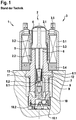
- FIG. 1 Fig. 3 is a schematic sectional view of a conventional solenoid valve. This has already been described as prior art.
- Fig. 2 furthermore shows schematically a chain of causes and effects.
- Possible inaccuracies in the individual components are shown in the illustrations at the top left.
- One of these inaccuracies is the material and manufacturing-related distortion of the valve element.
- Such inaccuracies can lead to tilting or an inclined position of the armature, for example with respect to the valve insert. This is shown in the illustration at the top right.
- the armature and / or the valve element can still rotate.
- These lead to a varying inclination of the armature for example with regard to the valve insert.
- varying inclinations of the armature cause a varying magnetic force acting on the armature. This is shown in the illustration below on the right.
- Fig. 3a and Figure 3b show embodiments of the invention.
- Fig. 3a defined contact points 6.3 on the face of the valve element 6 in direct plan view.
- the contact points 6.3 are defined and formed on the end face 6.4 of the valve element 6 facing the armature 4.
- a contact point 6.3 is formed on each wing of the valve element 6.
- the contact points 6.3 are positioned on the outer edge of the face 6.4, but slightly offset from the outer edge.
- the contact points 6.3 are longer in the circumferential direction than in the radial direction.
- the radial edges of the contact points 6.3 are aligned with the central axis 6.5 of the valve element 6.
- Figure 3b shows the embodiment in a side view.
- the valve element 6 is also shown here. It can be clearly seen that the contact points 6.3 formed are attached to the end face 6.4 of the valve element 6 facing the armature 4 and have different heights. The spacing between the contact points 6.3 is also shown. The illustrated heights of the contact points 6.3 are used for improved recognition. Furthermore, the closing element 6.1 and the main sealing element 6.2 and the spring device 7 are shown.
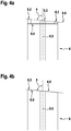
- Figures 4a, 4b and Figure 4c show embodiments of the invention, only the upper region of the valve element 6 being shown. Furthermore, the central axis 6.5 of the valve element 6 and the contact surface 6.6 are shown here. The angle a is defined between the contact surface 6.6 and the central axis 6.5 of the valve element.
- Figure 4a shows an embodiment in which four projections 6.3 define and represent the contact surface 6.6 (however, only three projections can be seen in the figure).
- a projection 6.3 is shown, which is formed by the inclined end face 6.4 of the valve element.
- the end face 6.4 has a profile. This profile has several projections 6.3, which serve as contact points for the anchor and thus the contact surface 6.6. form.
Landscapes
- Engineering & Computer Science (AREA)
- Physics & Mathematics (AREA)
- Mechanical Engineering (AREA)
- Transportation (AREA)
- Fluid Mechanics (AREA)
- Electromagnetism (AREA)
- General Engineering & Computer Science (AREA)
- General Physics & Mathematics (AREA)
- Automation & Control Theory (AREA)
- Magnetically Actuated Valves (AREA)
- Valves And Accessory Devices For Braking Systems (AREA)
Description
- Die vorliegende Erfindung betrifft ein Magnetventil zur Steuerung des Bremsdrucks einer Radbremse einer schlupfregelbaren Hydraulikbremsanlage eines Kraftfahrzeugs, mit einem längsbeweglich zumindest teilweise in einem Ventileinsatz angeordneten und mit einem Ventilsitz zusammenwirkenden Ventilelement, das in Einbaulage von einer Federeinrichtung mit einer in Öffnungsrichtung bzgl. des Ventilsitzes wirkenden Kraftkomponente beaufschlagt wird und mittels eines elektromagnetischen Aktuator in Schließrichtung bzgl. des Ventilsitzes betätigbar ist, wobei das Ventilelement zwischen einem Anker und dem Ventilsitz angeordnet ist und an dem Ventilelement eine Kontaktfläche ausgebildet ist, an welcher das Ventilelement mit dem Anker in Wirkverbindung steht, dadurch gekennzeichnet, dass die Kontaktfläche derart ausgebildet ist, dass zwischen einer Mittelachse des Ventilelements und der Kontaktfläche ein nicht-rechtwinkliger Schnittwinkel besteht.
- Aus dem Stand der Technik ist beispielsweise die Patentanmeldung
DE 10 2007 053 134 A1 bekannt. Diese Schrift betrifft ein Magnetventil, insbesondere für ein Hydraulikaggregat, welches beispielsweise in einem Antiblockiersystem (ABS) oder einem Antriebsschlupfregelsystem (ASR-System) oder einem elektronischen Stabilitätsprogrammsystem (ESP-System) eingesetzt wird. Ein solches ist inFigur 1 dargestellt. Wie ausFigur 1 ersichtlich ist, umfasst das Magnetventil 1, das beispielsweise als stromlos offenes Regelventil ausgeführt ist, eine Magnetbaugruppe 3 zur Erzeugung eines Magnetflusses, die einen Gehäusemantel 3.1, einen Wicklungsträger 3.2, eine Spulenwicklung 3.3 und eine Abdeckscheibe 3.4 umfasst, und eine Ventilpatrone 2, die eine Kapsel 2.1, einen mit einem ersten Ende in die Kapsel 2.1 eingeschobenen Ventileinsatz 8, einen Magnetanker 4 mit einem Ventilelement 6 (auch Stößel genannt) und eine Rückstellfeder 7 umfasst. Bei der Herstellung des Magnetventils 1 werden die Kapsel 2.1 und der Ventileinsatz 8 der Ventilpatrone 2 durch Pressen aufeinander gefügt und durch eine Dichtschweißung 2.2 wird die Ventilpatrone 2 hydraulisch gegenüber der Atmosphäre abgedichtet. Zusätzlich nimmt der Ventileinsatz 8 die im hydraulischen System auftretenden Druckkräfte auf und leitet diese über einen Verstemmflansch 11 an einen Verstemmbereich 12 eines Fluidblocks 13 weiter. - Die Magnetbaugruppe 3 erzeugt durch eine Bestromung der Spulenwicklung 3.3 über elektrischen Anschlüsse 3.5 eine Magnetkraft, die den längsbeweglichen Magnetanker 4 mit dem Ventilelement 6, der ein Schließelement 6.1 mit einem Hauptdichtelement 6.2 umfasst, entgegen der Kraft der Rückstellfeder 7 gegen den Ventileinsatz 8 bewegt, wobei das Ventilelement 6 und die Rückstellfeder 7 in einer Innenbohrung des Ventileinsatzes 2 geführt sind. Der Ventileinsatz 8 leitet den von der Magnetbaugruppe 3 über die Abdeckscheibe 3.4 eingeleiteten Magnetfluss axial über einen Luftspalt 5 in Richtung Magnetanker 4. Zudem nimmt der Ventileinsatz 8 an einem zweiten Ende den so genannten Ventilkörper 9 auf, der einen Hauptventilsitz 9.1 umfasst, in welchen das als Dichtkalotte ausgeführte Hauptdichtelement 6.2 dichtend eintaucht, um die Dichtfunktion des Magnetventils 1 umzusetzen. Wie weiter aus
Figur 1 ersichtlich ist, wird an den Ventileinsatz 8 axial ein Ventilunterteil 10 angelegt und abgestützt, das ein exzentrisch zur Ventilhauptachse angeordnetes Rückschlagventil 10.1 umfasst. Das beispielsweise als Kunststoffeinsatz ausgeführte Ventilunterteil 10 dient zusätzlich zur Abdichtung zum umgebenden Fluidblock 13, zur Abdichtung zum Ventilkörper 9 und zur Aufnahme eines Flachfilters 10.2. - Weiterhin ist aus dem Stand der Technik die Patentanmeldung
DE 10 2004 030 428 A1 bekannt. Diese Schrift betrifft eine elektromagnetische Ventilvorrichtung. Wenigstens ein Teil des Ventilelementes ist in einem von dem Ventileinsatz im Bereich des Ventilsitzes begrenzten Ventilraum angeordnet. Des Weiteren steht ein dem Ventilraum abgewandtes Ende des Ventilelementes mit einem Anker in Wirkverbindung. Hierbei ist eine dem Ventileinsatz zugewandte Stirnseite des Ankers und/oder eine der Stirnseiten des Ankers zugewandte Stirnseite des Ventileinsatzes mit einem derartigen Oberflächenprofil ausgeführt, dass ein von den Stirnseiten begrenzter Strömungsquerschnitt in radialer Richtung und/oder in Umfangsrichtung des Ankers wenigstens bereichsweise variiert. - Im Allgemeinen werden die Bauteile Ventilelement (Stößel) und Anker ungeführt (d.h. mit allen Freiheitsgraden) in das Ventil verbaut. Zudem sind die Bauteile zu einander lose montiert und können somit unterschiedlichste Orientierungen aufweisen. Teilweise weist das Ventilelement dabei eine etwas stärkere Führung durch das eingestellte Spiel auf als der Anker. Beim Anker handelt es sich häufig um ein kaltumgeformtes Stahlbauteil. Bei dem Ventilelement handelt es sich hingegen um ein Spritzgussteil, das aus faserverstärktem Kunststoff gefertigt wird. Die Herstellung erfolgt häufig mit seitlichem Anspritzpunkt. Bei der Herstellung des Ventilelements tritt aufgrund von Asymmetrien in der Faserorientierung ein Verzug im Bauteil auf. Dies führt dazu, dass auch die Anlagefläche am hinteren (dem Anker zugewandten) Ende des Ventilelements eine gewisse Schiefheit aufweist. Die resultierende Bauteilungenauigkeit (vor allem an Anker, Ventilelement) beeinflusst die Druckstellgenauigkeit sehr stark.
- Zudem können unterschiedliche Bauteilorientierungen zwischen Anker und Stößel auftreten und es dadurch zu Schwankungen bei der Druckstellung kommen (wie in
Fig. 2 dargestellt), weil sich eine Vielzahl unterschiedlicher Konstellationen zwischen Anker und Stößel einstellen kann und sich somit unterschiedliche Magnetkräfte ergeben. Bspw. kommt es durch eine Neuorientierung (Drehung) der Bauteile zu einer Änderung der Kontaktstellen. - Vorteilhaft ermöglicht hingegen das erfindungsgemäße Magnetventil eine Verbesserung der Druckstellgenauigkeit des Einlassventils sowie eine Vermeidung undefiniert wechselnder Magnetkräfte. Ermöglicht wird dies gemäß der Erfindung durch die Merkmale des unabhängigen Patentanspruchs. Weiterbildungen der Erfindung sind in den abhängigen Patentansprüchen angegeben.
- Das erfindungsgemäße Magnetventil zur Steuerung des Bremsdrucks einer Radbremse einer schlupfregelbaren Hydraulikbremsanlage eines Kraftfahrzeugs, mit einem längsbeweglich zumindest teilweise in einem Ventileinsatz angeordneten und mit einem Ventilsitz zusammenwirkenden Ventilelement, das in Einbaulage von einer Federeinrichtung mit einer in Öffnungsrichtung bezüglich des Ventilsitzes wirkenden Kraftkomponente beaufschlagt wird und mittels eines elektromagnetischen Aktuator in Schließrichtung bezüglich des Ventilsitzes betätigbar ist, wobei das Ventilelementes zwischen einem Anker und dem Ventilsitz angeordnet ist und an dem Ventilelement eine Kontaktfläche ausgebildet ist, an welcher das Ventilelement mit dem Anker in Wirkverbindung steht, dadurch gekennzeichnet, dass die Kontaktfläche derart ausgebildet ist, dass zwischen einer Mittelachse des Ventilelements und der Kontaktfläche ein nicht-rechtwinkliger Schnittwinkel besteht.
- Als Mittelachse des Ventilelements wird eine virtuelle Achse verstanden, die durch die geometrische Mitte des Querschnitts des Ventilelements verläuft. Die Mittelachse ist dabei parallel zur Umfangsfläche des Ventilelements. Die Mittelachse verläuft von dem Hauptdichtelement bis zu der dem Anker zugewandten Stirnseite. Sie folgt dabei einer evtl. Krümmung des Ventilelements. Als Kontaktfläche wird weiterhin eine virtuelle Fläche verstanden, die das Ventilelement begrenzt und dabei eine Berührungsfläche zum Anker darstellt, wenn beide Komponenten in Einbaulage in Kontakt miteinander stehen. Sie ist mittels einzelner Anlagepunkte oder auch Anlageflächen definiert. Die Kontaktfläche kann auch aus mehreren Kontaktpunkten oder mehreren Teilkontaktflächen bestehen. Die Kontaktfläche ist im Allgemeinen eben, das heißt zweidimensional. Als Kontaktfläche ist daher eine schiefe virtuelle Ebene an dem Ende des Ventilelements, welches dem Anker zugewandt ist, zu verstehen, wobei sich daran Kontaktstellen befinden, die eine Anlagesituation zwischen dem Ventilelement und dem Anker definieren. Als Schnittwinkel wird der kleinste Winkel verstanden, den die Mittelachse mit der Kontaktfläche bildet. Erfindungsgemäß ist nun vorgesehen dass die sich ergebende Kontaktfläche des Ventilelements einen vom rechten Winkel (d.h. 90°) abweichenden Winkel zur Mittelachse des Ventilelements in Höhe der Stirnfläche aufweist.
- Erfindungsgemäß ist das Ventilelement spritzgegossen und insbesondere faserverstärkt. Hierdurch kommt es, wie bereits ausgeführt, zu einem Verzug des Ventilelements. Bei einer Führung des Ventilelements im Ventileinsatz, würde sich daraus eine - in Bezug auf die Bewegungsrichtung des Ventilelements - schräge Stirnfläche des Ventilelements ausbilden. Aufgrund der losen Führung würde sich der Anker entsprechend dieser schrägen Stirnfläche des Ventilelements ausrichten. Dies würde bei einer Bewegung zu einem Verkippen des Ankers führen. Hieraus ergibt sich eine Variation der Magnetkraft und damit Variation der Druckstellgenauigkeit. Die Kompensation des fertigungsbedingten Verzugs des Bauteils ermöglicht somit eine verbesserte Druckstellgenauigkeit.
- Hierbei sei darauf verwiesen, dass nicht der Verzug des Bauteils direkt kompensiert wird, sondern die Auswirkungen des Verzugs des Ventilelements (Stößel) auf die Auflagefläche für den Anker werden kompensiert durch eine entsprechende geänderte Gestaltung der Stirnfläche, bzw. Kontaktfläche, welche die Auflagefläche für den Anker darstellt. Es wird im Grunde genommen in Bezug auf den Strößel eine schiefe Stirnfläche erstellt. Diese "schiefe" Ebene kompensiert die Verzüge (vor allem der Stößelspitze) beim Spritzen und erzeugen so einen möglichst gerade Stößel (bezogen auf die Funktionsrelevante Spitze).
- Hierfür wird der zu erwartende Verzug ermittelt, bspw. mittels Simulation oder Messung. Im Anschluss erfolgt eine Anpassung des Designs des Ventilelements, um den zu erwartenden Verzug zu berücksichtigen. Hierbei wird bspw. eine schiefe Kontaktfläche am hinteren Ende des Ventilelements geschaffen, um eine nicht-rechtwinklige Beziehung zwischen Mittelachse und Kontaktfläche auszubilden. Die schiefe Kontaktfläche kann mittels definierter Kontaktpunkte unterschiedlicher Höhe erzeugt werden. Hierbei können bspw. eine schiefe Stirnfläche oder Vorsprünge an der Stirnfläche vorgesehen sein. Die Anpassung und Ausbildung der Kontaktfläche erfolgt daher durch Auslegung der Endpunkte der Stirnfläche.
- Weiterhin erfolgt vorteilhaft eine klare Definition der Kontaktpunkte der Kontaktfläche. Hierdurch erfolgt eine Vermeidung von unterschiedlichen Kontaktsituationen zwischen Ventilelement und Anker. Dies verringert die Magnetkraftstreuung. Weiterhin reduziert dies die Variation des Ankerverkippens.
- In einer vorteilhaften Ausführungsform ist das Magnetventil dadurch gekennzeichnet, dass an der Stirnseite des Ventilelements wenigstens ein Vorsprung, insbesondere mehrere Vorsprünge, ausgebildet ist, welcher die Kontaktfläche definiert.
- Hierunter wird verstanden, dass die Stirnseite eine Erhebung (bspw. eine stufenförmige Erhebung) aufweist, mittels welcher die angesprochene (in Bezug auf das Ventilelement) schiefe Kontaktfläche ausgebildet wird. Alternativ sind mehrere Vorsprünge vorgesehen, d.h. wenigstens zwei, oder bspw. drei oder vier oder fünf Kontaktstellen. Die Vorsprünge werden auch als Pads (oder Kontaktpads) bezeichnet. Die Vorsprünge definieren die Kontaktpunkte zum Anker. Die verbleibende Fläche der Stirnfläche steht auch bei einem aneinander Anliegen nicht in Kontakt mit dem Anker. Die Stirnfläche des Ventilelements kann alternativ auch ein sonstiges Profil aufweisen, welches die schräge Kontaktfläche definiert und ausbildet. Auch kann eine schräge Stirnfläche selbst aufgrund der hervorgehobenen Fläche auf einer Seite als Vorsprung verstanden werden.
- Vorteilhaft ist hierbei die einfache Umsetzung zur Ausbildung der Kontaktfläche, welche nicht rechtwinklig hinsichtlich der Mittelachse des Ventilelements ist. Die Positionierung von Vorsprüngen an der Stirnseite ist mit einem geringen Fertigungsaufwand verbunden. Bspw. kann eine Anpassung des Werkzeugs (z.B. mittels einem Einstich) erfolgen, um die Vorsprünge im Spritzgussverfahren auszubilden. Weiterhin erfolgt bei mehreren Vorsprüngen eine gleichmäßige Verteilung der Krafteinleitung.
- In einer möglichen Ausgestaltung ist das Magnetventil dadurch gekennzeichnet, dass mehrere Vorsprünge ausgebildet sind, wobei diese:
- radial im selben Abstand zur Mittelachse des Ventilelements positioniert sind; und/oder
- auf der Stirnseite des Ventilelements zirkumferentiell voneinander beabstandet positioniert sind; und/oder
- symmetrisch verteilt zur Mittelachse auf der Stirnseite des Ventilelements positioniert sind; und/oder
- am äußeren Rand der Stirnseite des Ventilelements positioniert sind.
- Vorteilhaft ergibt sich hierdurch insbesondere eine Reduzierung oder sogar Vermeidung des Verkippens des Ankers. Weiterhin kann dadurch eine eindeutige Kontaktsituation zwischen dem Ventilelement und dem Anker ermöglicht werden. Darüber hinaus führen diese Ausgestaltungen zu einem gleichmäßigen Kraftfluss zwischen den Komponenten.
- In einer bevorzugten Ausführung ist das Magnetventil dadurch gekennzeichnet, dass die Kontaktfläche einen definierten Winkel zu der Mittelachse des Ventilelements aufweist.
- Hierunter wird verstanden, dass die durch das Ende des Ventilelements gebildete Anlagefläche für den Anker einen definierten nicht-rechtwinkligen Winkel aufweist. Eine Abweichung liegt in vorteilhafter Weise in der Größenordnung von 1°. Bspw. wurde eine Abweichung von 0,33° als vorteilhaft ermittelt. D.h. der Winkel zwischen der Mittelachse und der Kontaktfläche beträgt an minimaler Stelle 89,67°. Alternativ können Abweichungen von wenigen Grad, bspw. 5 bis 25° vorliegen. Vorteilhaft kann durch das Vorsehen eines definierten nicht-orthogonalen Winkels eine akkurate Einstellung der Kontaktfläche erfolgen. Dies ermöglicht eine genauere Führung des Ankers. Dies wiederum reduziert ein Verkippen des Ankers bei axialer Bewegung durch Schaffung einer Auflagefläche, die senkrecht zur Bewegungsrichtung des Ankers ist.
- In einer alternativen Weiterbildung ist das Magnetventil dadurch gekennzeichnet, dass der Winkel so definiert ist, dass die Kontaktfläche eine Bewegung des Ankers in axialer Richtung ohne ein Verkippen des Ankers ermöglicht.
- Vorteilhaft erfolgt hierdurch eine Verbesserung der Druckstellgenauigkeit, sowie ermöglicht dies einheitliche Magnetkräfte aufgrund der relativ konstanten Konstellation (und Anlagesituation) zwischen Anker und Ventilelement In einer vorteilhaften Ausgestaltung ist das Magnetventil dadurch gekennzeichnet, dass der Winkel so definiert ist, dass ein durch einen Produktionsprozess verursachter Verzug des Ventilelements durch den Winkel kompensiert wird.
- Unter dem Produktionsprozess wird erfindungsgemäß der Spritzguss vorzugsweise mit faserverstärktem Kunststoff verstanden. Bezüglich des Begriffs Kompensierung wird auf die obigen Ausführungen verwiesen. Vorteilhaft wird hierdurch eine geeignete Auflagefläche für den Anker geschaffen, um ein Verkippen dessen zu verhindern. Hierzu erfolgt eine Ausnutzung des reproduzierbaren Effekts des Verzugs bei bspw. faserverstärkten Kunststoffspritzgussteilen mit seitlicher Einspritzung in Abhängigkeit von der Faserorientierung. Eine Kompensation für die produzierten Bauteile wird somit ermöglicht.
- In einer möglichen Ausführung ist das Magnetventil dadurch gekennzeichnet, dass der Winkel so definiert ist, dass in Einbaulage des Ventilelements die Kontaktfläche orthogonal zu einer Bewegungsrichtung des Ventilelements ist; und/oder orthogonal zu einer Mittelachse des Magnetventils ist.
- Unter Einbaulage des Ventilelements wird das in dem Magnetventil eingebaute Ventilelement verstanden. Die Bewegungsrichtung des Ventilelements verläuft hierbei in Richtung der Mittelachse des Magnetventils. Ebenfalls verläuft die Bewegungsrichtung des Ankers in Richtung der Mittelachse des Magnetventils, so dass die Definition des Winkels der Kontaktfläche auch in Abhängigkeit der gewünschten Bewegungsrichtung des Ankers erfolgen kann. Vorteilhaft wird hierdurch eine geeignete Führung des Ankers ermöglicht. Dies ermöglicht eine Vermeidung des Verkippens des Ankers bei axialer Bewegung.
- In einer bevorzugten Weiterbildung ist das Magnetventil dadurch gekennzeichnet, dass die Höhe des Vorsprungs derart dimensioniert ist, dass hierdurch der definierte Winkel eingestellt wird.
- Hierdurch wird verstanden, dass sich die bspw. durch den Verzug einstellende Schräge der regulären Stirnfläche des Ventilelements im eingebauten Zustand mittels des Vorsprungs korrigiert wird. Hierfür werden der Vorsprung (oder die Vorsprünge) entsprechend definiert, insbesondere wird deren Höhe entsprechend ausgestaltet. Wie bereits ausgeführt, erfolgt eine derartige Definition unter Berücksichtigung der zu erwartenden Schrägstellen, bspw. aufgrund von Messwerten, Simulation oder Erfahrungswerten. Bei der Definition der Höhe der Vorsprünge können weiterhin Oberflächenungenauigkeiten berücksichtigt werden. Die Vorsprünge erlauben es also einen Abstand herzustellen und sicherzustellen, dass der Kontakt zwischen dem Ventilelement und dem Anker an den definierten Kontaktstellen auftritt und nicht an nicht definierten Unebenheiten. Vorteilhaft wird hierdurch eine Sicherstellung einer eindeutigen Anlagesituation ermöglicht, sowohl bei regulären Unebenheiten, als auch bei außergewöhnlichen Umständen, bspw. Werkstücken mit bedingtem Fehlermaß
- In einer alternativen Ausführungsform ist das Magnetventil dadurch gekennzeichnet, dass an der Stirnseite des Ventilelements wenigstens zwei Vorsprünge mit gleicher Höhe ausgebildet sind.
- Hierunter wird verstanden, dass zwei gleich hohe Vorsprünge vorhanden sind. Bspw. können auch bei vier Vorsprüngen 2 gleich hohe höhere Vorsprünge und 2 gleich hohe niedrigere Vorsprünge ausgestaltet sein. Vorteilhaft wird hierdurch die Schaffung definierter Kontaktstellen ermöglicht. Weiterhin erfolgt eine Reduzierung der Variation der Bauteilorientierungen.
- In einer vorteilhaften Ausgestaltung ist das Magnetventil dadurch gekennzeichnet, dass an der Stirnseite des Ventilelements wenigstens zwei Vorsprünge mit unterschiedlicher Höhe ausgebildet sind.
- Hierunter wird verstanden, dass wenigstens zwei Vorsprünge zur Einstellung der Kontaktfläche vorgesehen sind. Die beiden Vorsprünge weisen dabei zwei unterschiedliche Höhen auf. Hierdurch kann die Kontaktfläche definiert werden. Bspw. kann auch bei vier Vorsprüngen 4 unterschiedlich hohe Vorsprünge definiert und ausgestaltet werden. Bspw. können die 4 Padhöhen (abhängige Lage zum Anspritzpunkt) so definiert sein, dass sie eine Anlagefläche bilden, die zur hinteren Stirnfläche etwa 0,33° schief ist. Vorteilhaft ermöglicht dies die Schaffung einer schiefen Ebene als Kontaktfläche. Die schiefe Kontaktfläche wird dabei mittels einfacher Mittel während des regulären Gießprozesses mit erstellt. Bspw. kann hierfür eine Anpassung des Werkzeugs erfolgen. Hierbei eignen sich bspw. Einstiche, um die Vorsprünge zu erzeugen.
- In einer vorteilhaften Ausführungsform ist das Magnetventil dadurch gekennzeichnet, dass an der Stirnseite des Ventilelements drei Vorsprünge oder vier Vorsprünge ausgebildet sind.
- Hierunter wird verstanden, dass bspw. exakt drei Vorsprünge an der Stirnseite des Ventilelements definiert sind. Durch die Festlegung auf diese Anzahl kann eine Überbestimmung der Kontaktsituation vermieden werden. Hierdurch wird ein "Kippeln" des Ankers aufgrund der geometrischen Überbestimmung verhindert. In einer alternativen Ausführung sind jedoch auch vier oder 5 Vorsprünge denkbar. In einer alternativen Ausführungsform ist das Magnetventil dadurch gekennzeichnet, dass an jedem Flügel des Ventilelements jeweils ein Vorsprung ausgebildet ist. Hierunter wird verstanden, dass das Ventilelement axiale Aussparungen enthält, die bspw. den Fluidfluss positiv beeinflussen, weiterhin verbleiben zwischen den Aussparungen Flügel des Ventilelements, die eine radiale Führung ermöglichen. Bspw. können vier Flügel vorgesehen sein. Durch eine Positionierung der Kontaktstellen an den Flügeln, kann ein geeigneter Abstand der Kontaktstellen von der Mittelachse eingestellt werden. Vorteilhaft kann hierdurch eine Optimierung der Anlagesituation innerhalb der bestehenden Struktur und Geometrie des Ventilelements ermöglicht werden. Dies ermöglicht die beschriebenen Vorteile (insbesondere Reduzierung/Vermeidung Verkippen des Ankers sowie eindeutige Kontaktsituation) ohne Änderung des prinzipiellen aktuellen Designs des Ventilelements.
- In einer möglichen Ausgestaltung ist das Magnetventil dadurch gekennzeichnet, dass die Vorsprünge ebene Flächen aufweisen, wobei die ebenen Flächen insbesondere die Kontaktfläche darstellen, wobei die Kontaktfläche insbesondere einen Winkel zu der Mittelachse des Ventilelements aufweist.
- Hierunter wird verstanden, dass die Vorsprünge Flächen aufweisen, welche in Richtung des Ankers weisen. Diese Flächen dienen als Auflage- und Kontaktflächen zu dem Anker bei einem aneinander Anliegen des Ankers und des Ventilelements. Diese Flächen der Vorsprünge berücksichtigen die beschriebene Ausrichtung der Kontaktfläche und setzen diese fort. Vorteilhaft werden hierdurch große Auflagepunkte geschaffen, um eine geeignete Kraftleitung zu ermöglichen. Hierdurch werden punktuelle Kontakte vermieden. Hierdurch wird eine geeignete Flächenpressung ermöglicht.
- In einer bevorzugten Ausführung ist das Magnetventil dadurch gekennzeichnet, dass die Stirnseite des Ventilelements ein Profil aufweist, wobei insbesondere die Erhebungen des Profils die Kontaktfläche definieren.
- Hierunter wird verstanden, dass mittels eines ausgebildeten Profils auf der dem Anker zugewandten Stirnseite des Ventilelements die beschriebene schiefe Kontaktfläche erzeugt wird. Der Anker steht damit mit den Erhebungen des Profils in Kontakt. Hinsichtlich der Gestaltung des Profils sind beliebige Formen denkbar. Bspw. kann dieses aus Vertiefungen oder Mulden oder Wölbungen bestehen. Als Vorsprung könnten auch der verbleibende Randbereich oder eine hervortretende Wölbung (bspw. exzentrisch angeordnet) dienen. Bei der Auslegung des Profils kann weiterhin eine Optimierung dessen hinsichtlich des Fertigungsprozesses, der Bauteilbeständigkeit, einer Optimierung der Flächenpressung oder ähnliches durchgeführt werden. Ebenfalls ist eine Auslegung dahingehend denkbar, dass sich eine Variation des Kontaktpunktes während des Ankerhubs ergibt. Hierdurch könnte die Führung des Ankers optimiert werden.
- Erfindungsgemäß ist weiterhin ein Werkzeug zur Herstellung eines Ventilelements für ein Magnetventil zur Steuerung des Bremsdrucks einer Radbremse einer schlupfregelbaren Hydraulikbremsanlage eines Kraftfahrzeugs vorgesehen, wobei das Ventilelement längsbeweglich zumindest teilweise in einem Ventileinsatz angeordnet werden und mit einem Ventilsitz zusammenwirken kann, und wobei das Ventilelement in Einbaulage von einer Federeinrichtung mit einer in Öffnungsrichtung bezüglich des Ventilsitzes wirkenden Kraftkomponente beaufschlagbar ist und mittels eines elektromagnetischen Aktuator in Schließrichtung bezüglich des Ventilsitzes betätigbar ist, und wobei das Ventilelement zwischen einem Anker und dem Ventilsitz angeordnet werden kann und an dem Ventilelement eine Kontaktfläche ausgebildet ist, an welcher das Ventilelement mit dem Anker in Wirkverbindung steht, dadurch gekennzeichnet, dass das Werkzeug als Spritzgussform ausgebildet ist, wobei die Spritzgussform eingerichtet ist die Kontaktfläche des mittels der Spritzgussform herzustellenden Ventilelements derart auszubilden, dass zwischen einer Mittelachse des Ventilelements und der Kontaktfläche ein nicht-rechtwinkliger Schnittwinkel besteht.
- Hierunter wird ein Werkzeug verstanden, welches eingerichtet und ausgebildet ist, ein wie oben beschriebenes Ventilelement zu erzeugen. Der nicht-rechtwinklige Schnittwinkel zwischen der Mittelachse und der Kontaktfläche wird insbesondere auf das fertige Werkstück bezogen. Als Werkzeug kann bspw. eine Spritzgussform zur Herstellung des Ventilelements verstanden werden. Diese Spritzgussform kann bspw. Aussparungen zur Erzeugung der Vorsprünge der Stirnfläche des Ventilelements aufweisen.
- Zusammenfassend lässt sich formulieren: Bei der Herstellung des Stößels treten aufgrund von Asymmetrien in der Faserorientierung Verzüge des Bauteils auf. Dies führt dazu, dass auch die Anlagefläche am hinteren Ende Stößels eine gewisse Schiefheit aufweist. Da dieser Verzug stets an die Faserorientierung gebunden ist, ist eine Kompensation des Effekts im Werkzeug möglich. Durch geeignete Gestaltung des Werkzeuges (bspw. unterschiedliche Höhe der 4 Kontaktpads) wird sichergestellt, dass nach dem Erkalten des Bauteils die Schiefheit der Anlagefläche (welche durch die 4 Pads gebildet wird) minimiert wird.
- Es ist darauf hinzuweisen, dass die in der Beschreibung einzeln aufgeführten Merkmale in beliebiger, technisch sinnvoller Weise miteinander kombiniert werden können und weitere Ausgestaltungen der Erfindung aufzeigen. Weitere Merkmale und Zweckmäßigkeit der Erfindung ergeben sich aus der Beschreibung von Ausführungsbeispielen anhand der beigefügten Figuren.
-
-
Fig. 1 eine schematische Schnittansicht eines herkömmlichen Magnetventils; und -
Fig. 2 eine schematische Ursachen- und Wirkungskette hinsichtlich der Druckstellgenauigkeit und dem Ankerkippwinkel; und -
Fig. 3a eine schematische Ansicht eines Ausführungsbeispiels eines Ventilelements mit ausgebildeten Kontaktstellen in Aufsicht; und -
Fig. 3b eine schematische Ansicht eines Ausführungsbeispiels eines Ventilelements mit ausgebildeten Kontaktstellen in Seitenansicht; und -
Fig. 4a, 4b ,4c jeweils eine schematische Ansicht eines Ausführungsbeispiels eines Ventilelement im Teilausschnitt. - In
Fig. 1 ist eine schematische Schnittansicht eines herkömmlichen Magnetventils gezeigt. Dieses wurde bereits als Stand der Technik beschrieben. -
Fig. 2 zeigt weiterhin schematisch eine Ursachen- und Wirkungskette. Hierbei werden in den Darstellungen links oben mögliche Ungenauigkeiten in den einzelnen Bauteilen dargestellt. Eine dieser Ungenauigkeiten ist der material- und herstellungsbedingte Verzug des Ventilelements. Solche Ungenauigkeiten können zu einem Verkippen, bzw. zu einer Schrägstellung des Ankers bspw. hinsichtlich dem Ventileinsatz führen. Dies ist in der Darstellung rechts oben gezeigt. Bei einem Einsatz des Ventils kann es weiterhin zu Drehungen des Ankers und/oder der Ventilelements kommen. Diese führen zu einer variierenden Schrägstellung des Ankers bspw. hinsichtlich dem Ventileinsatz. Variierende Schrägstellungen des Ankers verursachen jedoch eine variierende auf den Anker wirkende Magnetkraft. Dies ist in der Darstellung rechts unten gezeigt. Die variierende auf den Anker wirkende Magnetkraft führt wiederum zu einer unterschiedlichen Strom-/Druck-Charakteristik des Ventils, wie dies in der Darstellung unten links abgebildet ist. Ungenauigkeiten in den Komponenten verursachen damit unterschiedliche Leistungscharakteristiken bei unterschiedlichen Ventilen - vielmehr sogar werden damit unterschiedliche Charakteristiken bei ein und demselben Ventil während des Ventileinsatzes erzeugt. -
Fig. 3a undFig. 3b zeigen Ausführungsformen der Erfindung. Hierbei zeigtFig. 3a definierte Kontaktstellen 6.3 auf der Stirnseite des Ventilelements 6 in direkten Aufsicht. Die Kontaktstellen 6.3 sind auf der zum Anker 4 weisenden Stirnseite 6.4 des Ventilelements 6 definiert und ausgebildet. Hierbei ist auf jedem Flügel des Ventilelements 6 jeweils eine Kontaktstelle 6.3 ausgebildet. Die Kontaktstellen 6.3 sind am äußeren Rand der Stirnseite 6.4 positioniert, jedoch leicht von der Außenkante abgesetzt. Die Kontaktstellen 6.3 sind in Umfangsrichtung länger als in radialer Richtung. Die radialen Kanten der Kontaktstellen 6.3 sind auf die Mittelachse 6.5 des Ventilelements 6 ausgerichtet. -
Fig. 3b zeigt das Ausführungsbeispiel in einer Seitenansicht. Hierbei ist ebenfalls das Ventilelement 6 dargestellt. Man sieht dabei deutlich, dass die ausgebildeten Kontaktstellen 6.3 auf der dem Anker 4 zugewandten Stirnseite 6.4 des Ventilelements 6 angebracht sind und unterschiedliche Höhen aufweisen. Weiterhin ist auch die Beabstandung der Kontaktstellen 6.3 dargestellt. Die dargestellten Höhen der Kontaktstellen 6.3 dienen der verbesserten Erkennung. Weiterhin sind das Schließelement 6.1 sowie das Hauptdichtelement 6.2 und die Federeinrichtung 7 dargestellt. -
Fig. 4a, 4b undFig. 4c zeigen Ausführungsformen der Erfindung, wobei lediglich der obere Bereich des Ventilelements 6 dargestellt ist. Weiterhin ist hier die Mittelachse 6.5 des Ventilelements 6 sowie die Kontaktfläche 6.6 eingezeichnet. Der Winkel a ist zwischen der Kontaktfläche 6.6 und der Mittelachse 6.5 des Ventilelements definiert.Fig. 4a zeigt ein Ausführungsbeispiel, bei dem vier Vorsprünge 6.3 die Kontaktfläche 6.6 definieren und darstellen (es sind jedoch lediglich drei Vorsprünge in der Abbildung zu sehen). InFig. 4b ist ein Vorsprung 6.3 eingezeichnet, welcher durch die schräggestellte Stirnseite 6.4 des Ventilelements gebildet wird. InFig. 4c weist die Stirnfläche 6.4 ein Profil auf. Dieses Profil besitzt mehrere Vorsprünge 6.3, welche als Anlagestellen für den Anker dienen und damit die Kontaktfläche 6.6. bilden.
Claims (13)
- Magnetventil (1) zur Steuerung eines Bremsdrucks einer Radbremse einer schlupfregelbaren Hydraulikbremsanlage eines Kraftfahrzeugs, mit einem längsbeweglich zumindest teilweise in einem Ventileinsatz (8) angeordneten und mit einem Ventilsitz (9.1) zusammenwirkenden Ventilelement (6), das in Einbaulage von einer Federeinrichtung (7) mit einer in Öffnungsrichtung bzgl. des Ventilsitzes (9.1) wirkenden Kraftkomponente beaufschlagt wird und mittels eines elektromagnetischen Aktuator (3) in Schließrichtung bzgl. des Ventilsitzes (9.1) betätigbar ist, wobei das Ventilelementes (6) zwischen einem Anker (4) und dem Ventilsitz (9.1) angeordnet ist und an dem Ventilelement (6) eine Kontaktfläche (6.6) ausgebildet ist, an welcher das Ventilelement (6) mit dem Anker (4) in Wirkverbindung steht, dadurch gekennzeichnet, dass die die Kontaktfläche (6.6) derart ausgebildet ist, dass zwischen einer Mittelachse (6.5) des Ventilelements (6) und der Kontaktfläche (6.6) ein nicht-rechtwinkliger Schnittwinkel (a) besteht.
- Magnetventil (1) nach Anspruch 1, dadurch gekennzeichnet, dass an der Stirnseite (6.4) des Ventilelements (6) wenigstens ein Vorsprung (6.3), insbesondere mehrere Vorsprünge (6.3), ausgebildet ist, welcher die Kontaktfläche (6.6) definiert.
- Magnetventil (1) nach einem der vorhergehenden Ansprüche, dadurch gekennzeichnet, dass die Kontaktfläche (6.6) einen definierten Schnittwinkel (a) zu der Mittelachse (6.5) des Ventilelements (6) aufweist.
- Magnetventil (1) nach Anspruch 3 dadurch gekennzeichnet, dass der Schnittwinkel (a) so definiert ist, dass die Kontaktfläche (6.6) eine Bewegung des Ankers (4) in axialer Richtung ohne ein Verkippen des Ankers (4) ermöglicht.
- Magnetventil nach einem der Ansprüche 3 oder 4, dadurch gekennzeichnet, dass der Schnittwinkel (a) so definiert ist, dass ein durch einen Produktionsprozess verursachter Verzug des Ventilelements (6) durch den Schnittwinkel (a) kompensiert wird.
- Magnetventil (1) nach einem der Ansprüche 3 bis 5, dadurch gekennzeichnet, dass der Schnittwinkel (a) so definiert ist, dass in Einbaulage des Ventilelements (6) die Kontaktfläche (6.6)- orthogonal zur Bewegungsrichtung des Ventilelements ist; und/oder- orthogonal zu einer Mittelachse des Magnetventils ist
- Magnetventil (1) nach einem der Ansprüche 2 bis 6, dadurch gekennzeichnet, dass die Höhe des Vorsprungs (6.3) derart dimensioniert ist, dass hierdurch der definierte Schnittwinkel (a) eingestellt wird.
- Magnetventil (1) nach einem der vorhergehenden Ansprüche, dadurch gekennzeichnet, dass an der Stirnseite (6.4) des Ventilelements (6) wenigstens zwei Vorsprünge (6.3) mit gleicher Höhe ausgebildet sind.
- Magnetventil (1) nach einem der vorhergehenden Ansprüche, dadurch gekennzeichnet, dass an der Stirnseite (6.4) des Ventilelements (6) wenigstens zwei Vorsprünge (6.3) mit unterschiedlicher Höhe ausgebildet sind.
- Magnetventil (1) nach einem der vorhergehenden Ansprüche, dadurch gekennzeichnet, dass an der Stirnseite (6.4) des Ventilelements (6) drei Vorsprünge (6.3) oder vier Vorsprünge (6.3) ausgebildet sind.
- Magnetventil (1) nach einem der vorhergehenden Ansprüche, dadurch gekennzeichnet, dass die Vorsprünge (6.3) ebene Flächen aufweisen, wobei die ebenen Flächen insbesondere die Kontaktfläche (6.6) darstellen, wobei die Kontaktfläche (6.6) insbesondere einen Schnittwinkel (a) zu der Mittelachse (6.5) des Ventilelements (6) aufweist.
- Magnetventil (1) nach einem der vorhergehenden Ansprüche, dadurch gekennzeichnet, dass die Stirnseite (6.4) des Ventilelements (6) ein Profil aufweist, wobei insbesondere die Erhebungen des Profils die Kontaktfläche (6.6) definieren.
- Werkzeug eingerichtet und ausgebildet zur Herstellung eines Ventilelements (6) für ein Magnetventil (1) zur Steuerung des Bremsdrucks einer Radbremse einer schlupfregelbaren Hydraulikbremsanlage eines Kraftfahrzeugs, wobei das Ventilelement (6) längsbeweglich zumindest teilweise in einem Ventileinsatz (8) angeordnet werden und mit einem Ventilsitz (9.1) zusammenwirken kann, und wobei das Ventilelement (6) in Einbaulage von einer Federeinrichtung (7) mit einer in Öffnungsrichtung bezüglich des Ventilsitzes (9.1) wirkenden Kraftkomponente beaufschlagbar ist und mittels eines elektromagnetischen Aktuator (3) in Schließrichtung bezüglich des Ventilsitzes (9.1) betätigbar ist, und wobei das Ventilelement (6) zwischen einem Anker (4) und dem Ventilsitz (9.1) angeordnet werden kann und an dem Ventilelement (6) eine Kontaktfläche (6.6) ausgebildet ist, an welcher das Ventilelement (6) mit dem Anker (4) in Wirkverbindung steht, dadurch gekennzeichnet, dass das Werkzeug als Spritzgussform ausgebildet ist, wobei die Spritzgussform eingerichtet ist die Kontaktfläche (6.6) des mittels der Spritzgussform herzustellenden Ventilelements (6) derart auszubilden, dass zwischen einer Mittelachse (6.5) des Ventilelements (6) und der Kontaktfläche (6.6) ein nicht-rechtwinkliger Schnittwinkel (a) besteht.
Applications Claiming Priority (2)
| Application Number | Priority Date | Filing Date | Title |
|---|---|---|---|
| DE102016220335.5A DE102016220335A1 (de) | 2016-10-18 | 2016-10-18 | Magnetventil zur Steuerung des Bremsdrucks einer Radbremse |
| PCT/EP2017/073830 WO2018072959A1 (de) | 2016-10-18 | 2017-09-20 | Magnetventil zur steuerung des bremsdrucks einer radbremse |
Publications (2)
| Publication Number | Publication Date |
|---|---|
| EP3529115A1 EP3529115A1 (de) | 2019-08-28 |
| EP3529115B1 true EP3529115B1 (de) | 2021-03-03 |
Family
ID=60037558
Family Applications (1)
| Application Number | Title | Priority Date | Filing Date |
|---|---|---|---|
| EP17780650.2A Active EP3529115B1 (de) | 2016-10-18 | 2017-09-20 | Magnetventil zur steuerung des bremsdrucks einer radbremse |
Country Status (6)
| Country | Link |
|---|---|
| US (1) | US11390259B2 (de) |
| EP (1) | EP3529115B1 (de) |
| JP (1) | JP6850879B2 (de) |
| CN (1) | CN109843667B (de) |
| DE (1) | DE102016220335A1 (de) |
| WO (1) | WO2018072959A1 (de) |
Families Citing this family (2)
| Publication number | Priority date | Publication date | Assignee | Title |
|---|---|---|---|---|
| DE102019215210A1 (de) * | 2019-10-02 | 2021-04-08 | Continental Teves Ag & Co. Ohg | Elektromagnetventil, insbesondere für schlupfgeregelte Kraftfahrzeugbremsanlagen |
| CN115875472B (zh) * | 2022-12-19 | 2023-10-13 | 江苏鑫鹏晟石油机械有限公司 | 一种旋塞阀压力自动控制装置 |
Family Cites Families (14)
| Publication number | Priority date | Publication date | Assignee | Title |
|---|---|---|---|---|
| DE19611832B4 (de) | 1996-03-26 | 2004-04-15 | Continental Teves Ag & Co. Ohg | Sitzventil |
| JP3364087B2 (ja) | 1996-07-25 | 2003-01-08 | 東京瓦斯株式会社 | 双方向遮断弁 |
| WO2001000473A1 (de) * | 1999-06-23 | 2001-01-04 | Continental Teves Ag & Co. Ohg | Elektromagnetventil, insbesondere für hydraulische bremsanlagen mit schlupfregelung |
| WO2001036242A1 (de) | 1999-11-16 | 2001-05-25 | Continental Teves Ag & Co. Ohg | Elektromagnetventil |
| US6387313B1 (en) | 1999-12-15 | 2002-05-14 | The Goodyear Tire & Rubber Company | Gate for injection molding rubber compounds |
| DE10311486A1 (de) * | 2002-09-27 | 2004-04-08 | Continental Teves Ag & Co. Ohg | Elektromagnetventil |
| DE102004030428A1 (de) * | 2004-06-24 | 2006-01-19 | Robert Bosch Gmbh | Ventilvorrichtung |
| DE102004030423A1 (de) * | 2004-06-24 | 2006-01-19 | Robert Bosch Gmbh | Ventilvorrichtung |
| DE102006003857A1 (de) | 2006-01-27 | 2007-08-02 | Robert Bosch Gmbh | Magnetventil |
| DE102007053134A1 (de) | 2007-11-08 | 2009-05-14 | Robert Bosch Gmbh | Ventilpatrone für ein Magnetventil und zugehöriges Magnetventil |
| JP2013210049A (ja) * | 2012-03-30 | 2013-10-10 | Denso Corp | 電磁弁 |
| DE202013100643U1 (de) * | 2013-02-13 | 2013-02-21 | Bürkert Werke GmbH | Magnetventil |
| WO2015001789A1 (ja) | 2013-07-01 | 2015-01-08 | 国立大学法人名古屋大学 | エンドミル加工装置およびcam装置およびncプログラム |
| JP6146774B2 (ja) * | 2013-12-12 | 2017-06-14 | 日立オートモティブシステムズ株式会社 | 電磁弁およびブレーキユニット |
-
2016
- 2016-10-18 DE DE102016220335.5A patent/DE102016220335A1/de not_active Withdrawn
-
2017
- 2017-09-20 EP EP17780650.2A patent/EP3529115B1/de active Active
- 2017-09-20 WO PCT/EP2017/073830 patent/WO2018072959A1/de not_active Ceased
- 2017-09-20 US US16/340,960 patent/US11390259B2/en active Active
- 2017-09-20 CN CN201780064268.3A patent/CN109843667B/zh active Active
- 2017-09-20 JP JP2019518982A patent/JP6850879B2/ja active Active
Non-Patent Citations (1)
| Title |
|---|
| None * |
Also Published As
| Publication number | Publication date |
|---|---|
| EP3529115A1 (de) | 2019-08-28 |
| CN109843667B (zh) | 2021-09-10 |
| US20190232936A1 (en) | 2019-08-01 |
| WO2018072959A1 (de) | 2018-04-26 |
| CN109843667A (zh) | 2019-06-04 |
| DE102016220335A1 (de) | 2018-04-19 |
| JP6850879B2 (ja) | 2021-03-31 |
| US11390259B2 (en) | 2022-07-19 |
| JP2019536949A (ja) | 2019-12-19 |
Similar Documents
| Publication | Publication Date | Title |
|---|---|---|
| EP2209679B1 (de) | Ventilpatrone für ein magnetventil und zugehöriges magnetventil | |
| EP3206214B1 (de) | Elektromagneteinrichtung sowie fahrerassistenzeinrichtung | |
| DE19700979A1 (de) | Magnetventil | |
| EP3924115B1 (de) | Umformwerkzeug und umformverfahren zur herstellung einer überdrucksollbruchstelle in einem batteriedeckel | |
| EP2219912B1 (de) | Ventilpatrone für ein magnetventil und zugehöriges magnetventil | |
| WO1999017014A1 (de) | Vorrichtung zum übertragen einer auslenkung, einspritzventil mit einer solchen vorrichtung und verfahren zum herstellen eines übertragungselementes | |
| DE102006003491B4 (de) | Magnetventil | |
| EP1816047A2 (de) | Magnetventil | |
| EP0581156A2 (de) | Hydraulisches Wegeventil in Kolbenschieber-Bauweise | |
| EP3529114B1 (de) | Magnetventil zur steuerung des bremsdrucks einer radbremse und werkzeug zur herstellung seines ventilelements | |
| WO2018072959A1 (de) | Magnetventil zur steuerung des bremsdrucks einer radbremse | |
| EP3445623B1 (de) | Hydraulikblock und herstellungsverfahren für einen hydraulikblock mit zumindest einem rückschlagventil | |
| EP1106817A2 (de) | Ventil mit verbesserter Anschlaggeometrie | |
| EP3280902B1 (de) | Gasventil | |
| DE102010002469B4 (de) | Verfahren zum Herstellen eines elektrisch betätigbaren Magnetkreisbauteils sowie Magnetkreisbeuteil | |
| EP1817216B1 (de) | Elektromagnetisch betätigbares ventil, insbesondere in einer bremsanlage eines kraftfahrzeuges | |
| EP1981746B1 (de) | Hydraulikaggregat | |
| DE102013213419A1 (de) | Neuartige Stößelspitzen-Geometrie für ein Druckregelventil | |
| WO2007085316A1 (de) | Magnetventil | |
| WO2014202665A1 (de) | Verfahren zum fügen von zwei oder mehreren bauteilen, verwendung zur herstellung eines pleuels und pleuel | |
| EP1813490B1 (de) | Magnetventil | |
| EP4515130B1 (de) | Magnetventil mit verbesserter luftführung und verfahren zu dessen herstellung | |
| DE102024124672A1 (de) | Druckregelventil zum Steuern oder Regeln eines Drucks eines Fluids in einem Pilotdruckraum und Schwingungsdämpfer mit einem solchen Druckregelventil | |
| DE102024120988A1 (de) | Druckregelventil zum Steuern oder Regeln eines Drucks eines Fluids in einem Pilotdruckraum und Schwingungsdämpfer mit einem solchen Druckregelventil | |
| DE102016205220A1 (de) | Gasventil zum Zuführen eines gasförmigen Kraftstoffs in den Ansaugtrakt einer Brennkraftmaschine |
Legal Events
| Date | Code | Title | Description |
|---|---|---|---|
| STAA | Information on the status of an ep patent application or granted ep patent |
Free format text: STATUS: UNKNOWN |
|
| STAA | Information on the status of an ep patent application or granted ep patent |
Free format text: STATUS: THE INTERNATIONAL PUBLICATION HAS BEEN MADE |
|
| PUAI | Public reference made under article 153(3) epc to a published international application that has entered the european phase |
Free format text: ORIGINAL CODE: 0009012 |
|
| STAA | Information on the status of an ep patent application or granted ep patent |
Free format text: STATUS: REQUEST FOR EXAMINATION WAS MADE |
|
| 17P | Request for examination filed |
Effective date: 20190520 |
|
| AK | Designated contracting states |
Kind code of ref document: A1 Designated state(s): AL AT BE BG CH CY CZ DE DK EE ES FI FR GB GR HR HU IE IS IT LI LT LU LV MC MK MT NL NO PL PT RO RS SE SI SK SM TR |
|
| AX | Request for extension of the european patent |
Extension state: BA ME |
|
| DAV | Request for validation of the european patent (deleted) | ||
| DAX | Request for extension of the european patent (deleted) | ||
| RAP1 | Party data changed (applicant data changed or rights of an application transferred) |
Owner name: ROBERT BOSCH GMBH |
|
| STAA | Information on the status of an ep patent application or granted ep patent |
Free format text: STATUS: EXAMINATION IS IN PROGRESS |
|
| 17Q | First examination report despatched |
Effective date: 20200623 |
|
| GRAP | Despatch of communication of intention to grant a patent |
Free format text: ORIGINAL CODE: EPIDOSNIGR1 |
|
| STAA | Information on the status of an ep patent application or granted ep patent |
Free format text: STATUS: GRANT OF PATENT IS INTENDED |
|
| INTG | Intention to grant announced |
Effective date: 20201120 |
|
| GRAS | Grant fee paid |
Free format text: ORIGINAL CODE: EPIDOSNIGR3 |
|
| GRAA | (expected) grant |
Free format text: ORIGINAL CODE: 0009210 |
|
| STAA | Information on the status of an ep patent application or granted ep patent |
Free format text: STATUS: THE PATENT HAS BEEN GRANTED |
|
| AK | Designated contracting states |
Kind code of ref document: B1 Designated state(s): AL AT BE BG CH CY CZ DE DK EE ES FI FR GB GR HR HU IE IS IT LI LT LU LV MC MK MT NL NO PL PT RO RS SE SI SK SM TR |
|
| REG | Reference to a national code |
Ref country code: GB Ref legal event code: FG4D Free format text: NOT ENGLISH |
|
| REG | Reference to a national code |
Ref country code: AT Ref legal event code: REF Ref document number: 1366891 Country of ref document: AT Kind code of ref document: T Effective date: 20210315 Ref country code: CH Ref legal event code: EP |
|
| REG | Reference to a national code |
Ref country code: DE Ref legal event code: R096 Ref document number: 502017009603 Country of ref document: DE |
|
| REG | Reference to a national code |
Ref country code: IE Ref legal event code: FG4D Free format text: LANGUAGE OF EP DOCUMENT: GERMAN |
|
| REG | Reference to a national code |
Ref country code: LT Ref legal event code: MG9D |
|
| PG25 | Lapsed in a contracting state [announced via postgrant information from national office to epo] |
Ref country code: LT Free format text: LAPSE BECAUSE OF FAILURE TO SUBMIT A TRANSLATION OF THE DESCRIPTION OR TO PAY THE FEE WITHIN THE PRESCRIBED TIME-LIMIT Effective date: 20210303 Ref country code: BG Free format text: LAPSE BECAUSE OF FAILURE TO SUBMIT A TRANSLATION OF THE DESCRIPTION OR TO PAY THE FEE WITHIN THE PRESCRIBED TIME-LIMIT Effective date: 20210603 Ref country code: NO Free format text: LAPSE BECAUSE OF FAILURE TO SUBMIT A TRANSLATION OF THE DESCRIPTION OR TO PAY THE FEE WITHIN THE PRESCRIBED TIME-LIMIT Effective date: 20210603 Ref country code: HR Free format text: LAPSE BECAUSE OF FAILURE TO SUBMIT A TRANSLATION OF THE DESCRIPTION OR TO PAY THE FEE WITHIN THE PRESCRIBED TIME-LIMIT Effective date: 20210303 Ref country code: GR Free format text: LAPSE BECAUSE OF FAILURE TO SUBMIT A TRANSLATION OF THE DESCRIPTION OR TO PAY THE FEE WITHIN THE PRESCRIBED TIME-LIMIT Effective date: 20210604 Ref country code: FI Free format text: LAPSE BECAUSE OF FAILURE TO SUBMIT A TRANSLATION OF THE DESCRIPTION OR TO PAY THE FEE WITHIN THE PRESCRIBED TIME-LIMIT Effective date: 20210303 |
|
| REG | Reference to a national code |
Ref country code: NL Ref legal event code: MP Effective date: 20210303 |
|
| PG25 | Lapsed in a contracting state [announced via postgrant information from national office to epo] |
Ref country code: PL Free format text: LAPSE BECAUSE OF FAILURE TO SUBMIT A TRANSLATION OF THE DESCRIPTION OR TO PAY THE FEE WITHIN THE PRESCRIBED TIME-LIMIT Effective date: 20210303 Ref country code: LV Free format text: LAPSE BECAUSE OF FAILURE TO SUBMIT A TRANSLATION OF THE DESCRIPTION OR TO PAY THE FEE WITHIN THE PRESCRIBED TIME-LIMIT Effective date: 20210303 Ref country code: RS Free format text: LAPSE BECAUSE OF FAILURE TO SUBMIT A TRANSLATION OF THE DESCRIPTION OR TO PAY THE FEE WITHIN THE PRESCRIBED TIME-LIMIT Effective date: 20210303 Ref country code: SE Free format text: LAPSE BECAUSE OF FAILURE TO SUBMIT A TRANSLATION OF THE DESCRIPTION OR TO PAY THE FEE WITHIN THE PRESCRIBED TIME-LIMIT Effective date: 20210303 |
|
| PG25 | Lapsed in a contracting state [announced via postgrant information from national office to epo] |
Ref country code: NL Free format text: LAPSE BECAUSE OF FAILURE TO SUBMIT A TRANSLATION OF THE DESCRIPTION OR TO PAY THE FEE WITHIN THE PRESCRIBED TIME-LIMIT Effective date: 20210303 |
|
| PG25 | Lapsed in a contracting state [announced via postgrant information from national office to epo] |
Ref country code: EE Free format text: LAPSE BECAUSE OF FAILURE TO SUBMIT A TRANSLATION OF THE DESCRIPTION OR TO PAY THE FEE WITHIN THE PRESCRIBED TIME-LIMIT Effective date: 20210303 Ref country code: CZ Free format text: LAPSE BECAUSE OF FAILURE TO SUBMIT A TRANSLATION OF THE DESCRIPTION OR TO PAY THE FEE WITHIN THE PRESCRIBED TIME-LIMIT Effective date: 20210303 Ref country code: SM Free format text: LAPSE BECAUSE OF FAILURE TO SUBMIT A TRANSLATION OF THE DESCRIPTION OR TO PAY THE FEE WITHIN THE PRESCRIBED TIME-LIMIT Effective date: 20210303 |
|
| PG25 | Lapsed in a contracting state [announced via postgrant information from national office to epo] |
Ref country code: RO Free format text: LAPSE BECAUSE OF FAILURE TO SUBMIT A TRANSLATION OF THE DESCRIPTION OR TO PAY THE FEE WITHIN THE PRESCRIBED TIME-LIMIT Effective date: 20210303 Ref country code: SK Free format text: LAPSE BECAUSE OF FAILURE TO SUBMIT A TRANSLATION OF THE DESCRIPTION OR TO PAY THE FEE WITHIN THE PRESCRIBED TIME-LIMIT Effective date: 20210303 Ref country code: PT Free format text: LAPSE BECAUSE OF FAILURE TO SUBMIT A TRANSLATION OF THE DESCRIPTION OR TO PAY THE FEE WITHIN THE PRESCRIBED TIME-LIMIT Effective date: 20210705 Ref country code: IS Free format text: LAPSE BECAUSE OF FAILURE TO SUBMIT A TRANSLATION OF THE DESCRIPTION OR TO PAY THE FEE WITHIN THE PRESCRIBED TIME-LIMIT Effective date: 20210703 |
|
| REG | Reference to a national code |
Ref country code: DE Ref legal event code: R097 Ref document number: 502017009603 Country of ref document: DE |
|
| PLBE | No opposition filed within time limit |
Free format text: ORIGINAL CODE: 0009261 |
|
| STAA | Information on the status of an ep patent application or granted ep patent |
Free format text: STATUS: NO OPPOSITION FILED WITHIN TIME LIMIT |
|
| PG25 | Lapsed in a contracting state [announced via postgrant information from national office to epo] |
Ref country code: DK Free format text: LAPSE BECAUSE OF FAILURE TO SUBMIT A TRANSLATION OF THE DESCRIPTION OR TO PAY THE FEE WITHIN THE PRESCRIBED TIME-LIMIT Effective date: 20210303 Ref country code: AL Free format text: LAPSE BECAUSE OF FAILURE TO SUBMIT A TRANSLATION OF THE DESCRIPTION OR TO PAY THE FEE WITHIN THE PRESCRIBED TIME-LIMIT Effective date: 20210303 Ref country code: ES Free format text: LAPSE BECAUSE OF FAILURE TO SUBMIT A TRANSLATION OF THE DESCRIPTION OR TO PAY THE FEE WITHIN THE PRESCRIBED TIME-LIMIT Effective date: 20210303 |
|
| 26N | No opposition filed |
Effective date: 20211206 |
|
| PG25 | Lapsed in a contracting state [announced via postgrant information from national office to epo] |
Ref country code: SI Free format text: LAPSE BECAUSE OF FAILURE TO SUBMIT A TRANSLATION OF THE DESCRIPTION OR TO PAY THE FEE WITHIN THE PRESCRIBED TIME-LIMIT Effective date: 20210303 |
|
| PG25 | Lapsed in a contracting state [announced via postgrant information from national office to epo] |
Ref country code: IT Free format text: LAPSE BECAUSE OF FAILURE TO SUBMIT A TRANSLATION OF THE DESCRIPTION OR TO PAY THE FEE WITHIN THE PRESCRIBED TIME-LIMIT Effective date: 20210303 |
|
| REG | Reference to a national code |
Ref country code: CH Ref legal event code: PL |
|
| REG | Reference to a national code |
Ref country code: BE Ref legal event code: MM Effective date: 20210930 |
|
| PG25 | Lapsed in a contracting state [announced via postgrant information from national office to epo] |
Ref country code: IS Free format text: LAPSE BECAUSE OF FAILURE TO SUBMIT A TRANSLATION OF THE DESCRIPTION OR TO PAY THE FEE WITHIN THE PRESCRIBED TIME-LIMIT Effective date: 20210703 Ref country code: MC Free format text: LAPSE BECAUSE OF FAILURE TO SUBMIT A TRANSLATION OF THE DESCRIPTION OR TO PAY THE FEE WITHIN THE PRESCRIBED TIME-LIMIT Effective date: 20210303 |
|
| PG25 | Lapsed in a contracting state [announced via postgrant information from national office to epo] |
Ref country code: LU Free format text: LAPSE BECAUSE OF NON-PAYMENT OF DUE FEES Effective date: 20210920 Ref country code: IE Free format text: LAPSE BECAUSE OF NON-PAYMENT OF DUE FEES Effective date: 20210920 Ref country code: BE Free format text: LAPSE BECAUSE OF NON-PAYMENT OF DUE FEES Effective date: 20210930 |
|
| PG25 | Lapsed in a contracting state [announced via postgrant information from national office to epo] |
Ref country code: LI Free format text: LAPSE BECAUSE OF NON-PAYMENT OF DUE FEES Effective date: 20210930 Ref country code: CH Free format text: LAPSE BECAUSE OF NON-PAYMENT OF DUE FEES Effective date: 20210930 |
|
| PG25 | Lapsed in a contracting state [announced via postgrant information from national office to epo] |
Ref country code: CY Free format text: LAPSE BECAUSE OF FAILURE TO SUBMIT A TRANSLATION OF THE DESCRIPTION OR TO PAY THE FEE WITHIN THE PRESCRIBED TIME-LIMIT Effective date: 20210303 |
|
| PG25 | Lapsed in a contracting state [announced via postgrant information from national office to epo] |
Ref country code: HU Free format text: LAPSE BECAUSE OF FAILURE TO SUBMIT A TRANSLATION OF THE DESCRIPTION OR TO PAY THE FEE WITHIN THE PRESCRIBED TIME-LIMIT; INVALID AB INITIO Effective date: 20170920 |
|
| REG | Reference to a national code |
Ref country code: AT Ref legal event code: MM01 Ref document number: 1366891 Country of ref document: AT Kind code of ref document: T Effective date: 20220920 |
|
| PG25 | Lapsed in a contracting state [announced via postgrant information from national office to epo] |
Ref country code: AT Free format text: LAPSE BECAUSE OF NON-PAYMENT OF DUE FEES Effective date: 20220920 |
|
| PG25 | Lapsed in a contracting state [announced via postgrant information from national office to epo] |
Ref country code: MK Free format text: LAPSE BECAUSE OF FAILURE TO SUBMIT A TRANSLATION OF THE DESCRIPTION OR TO PAY THE FEE WITHIN THE PRESCRIBED TIME-LIMIT Effective date: 20210303 |
|
| PG25 | Lapsed in a contracting state [announced via postgrant information from national office to epo] |
Ref country code: MT Free format text: LAPSE BECAUSE OF FAILURE TO SUBMIT A TRANSLATION OF THE DESCRIPTION OR TO PAY THE FEE WITHIN THE PRESCRIBED TIME-LIMIT Effective date: 20210303 |
|
| PGFP | Annual fee paid to national office [announced via postgrant information from national office to epo] |
Ref country code: GB Payment date: 20250923 Year of fee payment: 9 |
|
| PGFP | Annual fee paid to national office [announced via postgrant information from national office to epo] |
Ref country code: FR Payment date: 20250922 Year of fee payment: 9 |
|
| PG25 | Lapsed in a contracting state [announced via postgrant information from national office to epo] |
Ref country code: TR Free format text: LAPSE BECAUSE OF FAILURE TO SUBMIT A TRANSLATION OF THE DESCRIPTION OR TO PAY THE FEE WITHIN THE PRESCRIBED TIME-LIMIT Effective date: 20210303 |
|
| PGFP | Annual fee paid to national office [announced via postgrant information from national office to epo] |
Ref country code: DE Payment date: 20251121 Year of fee payment: 9 |