EP3528362A1 - Charging facility and energy management method for charging facility - Google Patents
Charging facility and energy management method for charging facility Download PDFInfo
- Publication number
- EP3528362A1 EP3528362A1 EP19165645.3A EP19165645A EP3528362A1 EP 3528362 A1 EP3528362 A1 EP 3528362A1 EP 19165645 A EP19165645 A EP 19165645A EP 3528362 A1 EP3528362 A1 EP 3528362A1
- Authority
- EP
- European Patent Office
- Prior art keywords
- power
- voltage
- power supply
- direct current
- current bus
- Prior art date
- Legal status (The legal status is an assumption and is not a legal conclusion. Google has not performed a legal analysis and makes no representation as to the accuracy of the status listed.)
- Granted
Links
Images


Classifications
-
- B—PERFORMING OPERATIONS; TRANSPORTING
- B60—VEHICLES IN GENERAL
- B60L—PROPULSION OF ELECTRICALLY-PROPELLED VEHICLES; SUPPLYING ELECTRIC POWER FOR AUXILIARY EQUIPMENT OF ELECTRICALLY-PROPELLED VEHICLES; ELECTRODYNAMIC BRAKE SYSTEMS FOR VEHICLES IN GENERAL; MAGNETIC SUSPENSION OR LEVITATION FOR VEHICLES; MONITORING OPERATING VARIABLES OF ELECTRICALLY-PROPELLED VEHICLES; ELECTRIC SAFETY DEVICES FOR ELECTRICALLY-PROPELLED VEHICLES
- B60L53/00—Methods of charging batteries, specially adapted for electric vehicles; Charging stations or on-board charging equipment therefor; Exchange of energy storage elements in electric vehicles
- B60L53/20—Methods of charging batteries, specially adapted for electric vehicles; Charging stations or on-board charging equipment therefor; Exchange of energy storage elements in electric vehicles characterised by converters located in the vehicle
- B60L53/22—Constructional details or arrangements of charging converters specially adapted for charging electric vehicles
-
- B—PERFORMING OPERATIONS; TRANSPORTING
- B60—VEHICLES IN GENERAL
- B60L—PROPULSION OF ELECTRICALLY-PROPELLED VEHICLES; SUPPLYING ELECTRIC POWER FOR AUXILIARY EQUIPMENT OF ELECTRICALLY-PROPELLED VEHICLES; ELECTRODYNAMIC BRAKE SYSTEMS FOR VEHICLES IN GENERAL; MAGNETIC SUSPENSION OR LEVITATION FOR VEHICLES; MONITORING OPERATING VARIABLES OF ELECTRICALLY-PROPELLED VEHICLES; ELECTRIC SAFETY DEVICES FOR ELECTRICALLY-PROPELLED VEHICLES
- B60L53/00—Methods of charging batteries, specially adapted for electric vehicles; Charging stations or on-board charging equipment therefor; Exchange of energy storage elements in electric vehicles
- B60L53/30—Constructional details of charging stations
-
- B—PERFORMING OPERATIONS; TRANSPORTING
- B60—VEHICLES IN GENERAL
- B60L—PROPULSION OF ELECTRICALLY-PROPELLED VEHICLES; SUPPLYING ELECTRIC POWER FOR AUXILIARY EQUIPMENT OF ELECTRICALLY-PROPELLED VEHICLES; ELECTRODYNAMIC BRAKE SYSTEMS FOR VEHICLES IN GENERAL; MAGNETIC SUSPENSION OR LEVITATION FOR VEHICLES; MONITORING OPERATING VARIABLES OF ELECTRICALLY-PROPELLED VEHICLES; ELECTRIC SAFETY DEVICES FOR ELECTRICALLY-PROPELLED VEHICLES
- B60L53/00—Methods of charging batteries, specially adapted for electric vehicles; Charging stations or on-board charging equipment therefor; Exchange of energy storage elements in electric vehicles
- B60L53/50—Charging stations characterised by energy-storage or power-generation means
- B60L53/51—Photovoltaic means
-
- B—PERFORMING OPERATIONS; TRANSPORTING
- B60—VEHICLES IN GENERAL
- B60L—PROPULSION OF ELECTRICALLY-PROPELLED VEHICLES; SUPPLYING ELECTRIC POWER FOR AUXILIARY EQUIPMENT OF ELECTRICALLY-PROPELLED VEHICLES; ELECTRODYNAMIC BRAKE SYSTEMS FOR VEHICLES IN GENERAL; MAGNETIC SUSPENSION OR LEVITATION FOR VEHICLES; MONITORING OPERATING VARIABLES OF ELECTRICALLY-PROPELLED VEHICLES; ELECTRIC SAFETY DEVICES FOR ELECTRICALLY-PROPELLED VEHICLES
- B60L53/00—Methods of charging batteries, specially adapted for electric vehicles; Charging stations or on-board charging equipment therefor; Exchange of energy storage elements in electric vehicles
- B60L53/50—Charging stations characterised by energy-storage or power-generation means
- B60L53/53—Batteries
-
- B—PERFORMING OPERATIONS; TRANSPORTING
- B60—VEHICLES IN GENERAL
- B60L—PROPULSION OF ELECTRICALLY-PROPELLED VEHICLES; SUPPLYING ELECTRIC POWER FOR AUXILIARY EQUIPMENT OF ELECTRICALLY-PROPELLED VEHICLES; ELECTRODYNAMIC BRAKE SYSTEMS FOR VEHICLES IN GENERAL; MAGNETIC SUSPENSION OR LEVITATION FOR VEHICLES; MONITORING OPERATING VARIABLES OF ELECTRICALLY-PROPELLED VEHICLES; ELECTRIC SAFETY DEVICES FOR ELECTRICALLY-PROPELLED VEHICLES
- B60L53/00—Methods of charging batteries, specially adapted for electric vehicles; Charging stations or on-board charging equipment therefor; Exchange of energy storage elements in electric vehicles
- B60L53/60—Monitoring or controlling charging stations
- B60L53/67—Controlling two or more charging stations
-
- H—ELECTRICITY
- H02—GENERATION; CONVERSION OR DISTRIBUTION OF ELECTRIC POWER
- H02J—ELECTRIC POWER NETWORKS; CIRCUIT ARRANGEMENTS OR SYSTEMS FOR SUPPLYING OR DISTRIBUTING ELECTRIC POWER; SYSTEMS FOR STORING ELECTRIC ENERGY
- H02J3/00—Circuit arrangements for AC mains or AC distribution networks
- H02J3/38—Arrangements for feeding a single network from two or more generators or sources in parallel; Arrangements for feeding already energised networks from additional generators or sources in parallel
- H02J3/381—Dispersed generators
-
- H—ELECTRICITY
- H02—GENERATION; CONVERSION OR DISTRIBUTION OF ELECTRIC POWER
- H02J—ELECTRIC POWER NETWORKS; CIRCUIT ARRANGEMENTS OR SYSTEMS FOR SUPPLYING OR DISTRIBUTING ELECTRIC POWER; SYSTEMS FOR STORING ELECTRIC ENERGY
- H02J3/00—Circuit arrangements for AC mains or AC distribution networks
- H02J3/38—Arrangements for feeding a single network from two or more generators or sources in parallel; Arrangements for feeding already energised networks from additional generators or sources in parallel
- H02J3/46—Controlling the sharing of generated power between the generators, sources or networks
-
- H—ELECTRICITY
- H02—GENERATION; CONVERSION OR DISTRIBUTION OF ELECTRIC POWER
- H02J—ELECTRIC POWER NETWORKS; CIRCUIT ARRANGEMENTS OR SYSTEMS FOR SUPPLYING OR DISTRIBUTING ELECTRIC POWER; SYSTEMS FOR STORING ELECTRIC ENERGY
- H02J7/00—Circuit arrangements for charging or discharging batteries or for supplying loads from batteries
- H02J7/02—Circuit arrangements for charging or discharging batteries or for supplying loads from batteries for charging batteries from AC mains by converters
-
- H—ELECTRICITY
- H02—GENERATION; CONVERSION OR DISTRIBUTION OF ELECTRIC POWER
- H02J—ELECTRIC POWER NETWORKS; CIRCUIT ARRANGEMENTS OR SYSTEMS FOR SUPPLYING OR DISTRIBUTING ELECTRIC POWER; SYSTEMS FOR STORING ELECTRIC ENERGY
- H02J7/00—Circuit arrangements for charging or discharging batteries or for supplying loads from batteries
- H02J7/34—Parallel operation in networks using both storage and other DC sources, e.g. providing buffering
- H02J7/35—Parallel operation in networks using both storage and other DC sources, e.g. providing buffering with light sensitive cells
-
- H—ELECTRICITY
- H02—GENERATION; CONVERSION OR DISTRIBUTION OF ELECTRIC POWER
- H02J—ELECTRIC POWER NETWORKS; CIRCUIT ARRANGEMENTS OR SYSTEMS FOR SUPPLYING OR DISTRIBUTING ELECTRIC POWER; SYSTEMS FOR STORING ELECTRIC ENERGY
- H02J7/00—Circuit arrangements for charging or discharging batteries or for supplying loads from batteries
- H02J7/865—Battery or charger load switching, e.g. concurrent charging and load supply
-
- H—ELECTRICITY
- H02—GENERATION; CONVERSION OR DISTRIBUTION OF ELECTRIC POWER
- H02K—DYNAMO-ELECTRIC MACHINES
- H02K47/00—Dynamo-electric converters
- H02K47/12—DC/DC converters
- H02K47/14—Motor/generators
-
- B—PERFORMING OPERATIONS; TRANSPORTING
- B60—VEHICLES IN GENERAL
- B60L—PROPULSION OF ELECTRICALLY-PROPELLED VEHICLES; SUPPLYING ELECTRIC POWER FOR AUXILIARY EQUIPMENT OF ELECTRICALLY-PROPELLED VEHICLES; ELECTRODYNAMIC BRAKE SYSTEMS FOR VEHICLES IN GENERAL; MAGNETIC SUSPENSION OR LEVITATION FOR VEHICLES; MONITORING OPERATING VARIABLES OF ELECTRICALLY-PROPELLED VEHICLES; ELECTRIC SAFETY DEVICES FOR ELECTRICALLY-PROPELLED VEHICLES
- B60L2210/00—Converter types
- B60L2210/10—DC to DC converters
-
- H—ELECTRICITY
- H02—GENERATION; CONVERSION OR DISTRIBUTION OF ELECTRIC POWER
- H02J—ELECTRIC POWER NETWORKS; CIRCUIT ARRANGEMENTS OR SYSTEMS FOR SUPPLYING OR DISTRIBUTING ELECTRIC POWER; SYSTEMS FOR STORING ELECTRIC ENERGY
- H02J2101/00—Supply or distribution of decentralised, dispersed or local electric power generation
- H02J2101/20—Dispersed power generation using renewable energy sources
- H02J2101/22—Solar energy
- H02J2101/24—Photovoltaics
-
- H—ELECTRICITY
- H02—GENERATION; CONVERSION OR DISTRIBUTION OF ELECTRIC POWER
- H02J—ELECTRIC POWER NETWORKS; CIRCUIT ARRANGEMENTS OR SYSTEMS FOR SUPPLYING OR DISTRIBUTING ELECTRIC POWER; SYSTEMS FOR STORING ELECTRIC ENERGY
- H02J2105/00—Networks for supplying or distributing electric power characterised by their spatial reach or by the load
- H02J2105/30—Networks for supplying or distributing electric power characterised by their spatial reach or by the load the load networks being external to vehicles, i.e. exchanging power with vehicles
- H02J2105/33—Networks for supplying or distributing electric power characterised by their spatial reach or by the load the load networks being external to vehicles, i.e. exchanging power with vehicles exchanging power with road vehicles
- H02J2105/37—Networks for supplying or distributing electric power characterised by their spatial reach or by the load the load networks being external to vehicles, i.e. exchanging power with vehicles exchanging power with road vehicles exchanging power with electric vehicles [EV] or with hybrid electric vehicles [HEV]
-
- H—ELECTRICITY
- H02—GENERATION; CONVERSION OR DISTRIBUTION OF ELECTRIC POWER
- H02J—ELECTRIC POWER NETWORKS; CIRCUIT ARRANGEMENTS OR SYSTEMS FOR SUPPLYING OR DISTRIBUTING ELECTRIC POWER; SYSTEMS FOR STORING ELECTRIC ENERGY
- H02J2207/00—Details of circuit arrangements for charging or discharging batteries or supplying loads from batteries
- H02J2207/20—Charging or discharging characterised by the power electronics converter
-
- H—ELECTRICITY
- H02—GENERATION; CONVERSION OR DISTRIBUTION OF ELECTRIC POWER
- H02J—ELECTRIC POWER NETWORKS; CIRCUIT ARRANGEMENTS OR SYSTEMS FOR SUPPLYING OR DISTRIBUTING ELECTRIC POWER; SYSTEMS FOR STORING ELECTRIC ENERGY
- H02J3/00—Circuit arrangements for AC mains or AC distribution networks
- H02J3/28—Arrangements for balancing of the load in networks by storage of energy
- H02J3/32—Arrangements for balancing of the load in networks by storage of energy using batteries or super capacitors with converting means
-
- Y—GENERAL TAGGING OF NEW TECHNOLOGICAL DEVELOPMENTS; GENERAL TAGGING OF CROSS-SECTIONAL TECHNOLOGIES SPANNING OVER SEVERAL SECTIONS OF THE IPC; TECHNICAL SUBJECTS COVERED BY FORMER USPC CROSS-REFERENCE ART COLLECTIONS [XRACs] AND DIGESTS
- Y02—TECHNOLOGIES OR APPLICATIONS FOR MITIGATION OR ADAPTATION AGAINST CLIMATE CHANGE
- Y02E—REDUCTION OF GREENHOUSE GAS [GHG] EMISSIONS, RELATED TO ENERGY GENERATION, TRANSMISSION OR DISTRIBUTION
- Y02E10/00—Energy generation through renewable energy sources
- Y02E10/50—Photovoltaic [PV] energy
- Y02E10/56—Power conversion systems, e.g. maximum power point trackers
-
- Y—GENERAL TAGGING OF NEW TECHNOLOGICAL DEVELOPMENTS; GENERAL TAGGING OF CROSS-SECTIONAL TECHNOLOGIES SPANNING OVER SEVERAL SECTIONS OF THE IPC; TECHNICAL SUBJECTS COVERED BY FORMER USPC CROSS-REFERENCE ART COLLECTIONS [XRACs] AND DIGESTS
- Y02—TECHNOLOGIES OR APPLICATIONS FOR MITIGATION OR ADAPTATION AGAINST CLIMATE CHANGE
- Y02E—REDUCTION OF GREENHOUSE GAS [GHG] EMISSIONS, RELATED TO ENERGY GENERATION, TRANSMISSION OR DISTRIBUTION
- Y02E10/00—Energy generation through renewable energy sources
- Y02E10/70—Wind energy
- Y02E10/76—Power conversion electric or electronic aspects
-
- Y—GENERAL TAGGING OF NEW TECHNOLOGICAL DEVELOPMENTS; GENERAL TAGGING OF CROSS-SECTIONAL TECHNOLOGIES SPANNING OVER SEVERAL SECTIONS OF THE IPC; TECHNICAL SUBJECTS COVERED BY FORMER USPC CROSS-REFERENCE ART COLLECTIONS [XRACs] AND DIGESTS
- Y02—TECHNOLOGIES OR APPLICATIONS FOR MITIGATION OR ADAPTATION AGAINST CLIMATE CHANGE
- Y02E—REDUCTION OF GREENHOUSE GAS [GHG] EMISSIONS, RELATED TO ENERGY GENERATION, TRANSMISSION OR DISTRIBUTION
- Y02E60/00—Enabling technologies; Technologies with a potential or indirect contribution to GHG emissions mitigation
-
- Y—GENERAL TAGGING OF NEW TECHNOLOGICAL DEVELOPMENTS; GENERAL TAGGING OF CROSS-SECTIONAL TECHNOLOGIES SPANNING OVER SEVERAL SECTIONS OF THE IPC; TECHNICAL SUBJECTS COVERED BY FORMER USPC CROSS-REFERENCE ART COLLECTIONS [XRACs] AND DIGESTS
- Y02—TECHNOLOGIES OR APPLICATIONS FOR MITIGATION OR ADAPTATION AGAINST CLIMATE CHANGE
- Y02T—CLIMATE CHANGE MITIGATION TECHNOLOGIES RELATED TO TRANSPORTATION
- Y02T10/00—Road transport of goods or passengers
- Y02T10/60—Other road transportation technologies with climate change mitigation effect
- Y02T10/70—Energy storage systems for electromobility, e.g. batteries
-
- Y—GENERAL TAGGING OF NEW TECHNOLOGICAL DEVELOPMENTS; GENERAL TAGGING OF CROSS-SECTIONAL TECHNOLOGIES SPANNING OVER SEVERAL SECTIONS OF THE IPC; TECHNICAL SUBJECTS COVERED BY FORMER USPC CROSS-REFERENCE ART COLLECTIONS [XRACs] AND DIGESTS
- Y02—TECHNOLOGIES OR APPLICATIONS FOR MITIGATION OR ADAPTATION AGAINST CLIMATE CHANGE
- Y02T—CLIMATE CHANGE MITIGATION TECHNOLOGIES RELATED TO TRANSPORTATION
- Y02T10/00—Road transport of goods or passengers
- Y02T10/60—Other road transportation technologies with climate change mitigation effect
- Y02T10/7072—Electromobility specific charging systems or methods for batteries, ultracapacitors, supercapacitors or double-layer capacitors
-
- Y—GENERAL TAGGING OF NEW TECHNOLOGICAL DEVELOPMENTS; GENERAL TAGGING OF CROSS-SECTIONAL TECHNOLOGIES SPANNING OVER SEVERAL SECTIONS OF THE IPC; TECHNICAL SUBJECTS COVERED BY FORMER USPC CROSS-REFERENCE ART COLLECTIONS [XRACs] AND DIGESTS
- Y02—TECHNOLOGIES OR APPLICATIONS FOR MITIGATION OR ADAPTATION AGAINST CLIMATE CHANGE
- Y02T—CLIMATE CHANGE MITIGATION TECHNOLOGIES RELATED TO TRANSPORTATION
- Y02T10/00—Road transport of goods or passengers
- Y02T10/60—Other road transportation technologies with climate change mitigation effect
- Y02T10/72—Electric energy management in electromobility
-
- Y—GENERAL TAGGING OF NEW TECHNOLOGICAL DEVELOPMENTS; GENERAL TAGGING OF CROSS-SECTIONAL TECHNOLOGIES SPANNING OVER SEVERAL SECTIONS OF THE IPC; TECHNICAL SUBJECTS COVERED BY FORMER USPC CROSS-REFERENCE ART COLLECTIONS [XRACs] AND DIGESTS
- Y02—TECHNOLOGIES OR APPLICATIONS FOR MITIGATION OR ADAPTATION AGAINST CLIMATE CHANGE
- Y02T—CLIMATE CHANGE MITIGATION TECHNOLOGIES RELATED TO TRANSPORTATION
- Y02T10/00—Road transport of goods or passengers
- Y02T10/80—Technologies aiming to reduce greenhouse gasses emissions common to all road transportation technologies
- Y02T10/92—Energy efficient charging or discharging systems for batteries, ultracapacitors, supercapacitors or double-layer capacitors specially adapted for vehicles
-
- Y—GENERAL TAGGING OF NEW TECHNOLOGICAL DEVELOPMENTS; GENERAL TAGGING OF CROSS-SECTIONAL TECHNOLOGIES SPANNING OVER SEVERAL SECTIONS OF THE IPC; TECHNICAL SUBJECTS COVERED BY FORMER USPC CROSS-REFERENCE ART COLLECTIONS [XRACs] AND DIGESTS
- Y02—TECHNOLOGIES OR APPLICATIONS FOR MITIGATION OR ADAPTATION AGAINST CLIMATE CHANGE
- Y02T—CLIMATE CHANGE MITIGATION TECHNOLOGIES RELATED TO TRANSPORTATION
- Y02T90/00—Enabling technologies or technologies with a potential or indirect contribution to GHG emissions mitigation
- Y02T90/10—Technologies relating to charging of electric vehicles
- Y02T90/12—Electric charging stations
-
- Y—GENERAL TAGGING OF NEW TECHNOLOGICAL DEVELOPMENTS; GENERAL TAGGING OF CROSS-SECTIONAL TECHNOLOGIES SPANNING OVER SEVERAL SECTIONS OF THE IPC; TECHNICAL SUBJECTS COVERED BY FORMER USPC CROSS-REFERENCE ART COLLECTIONS [XRACs] AND DIGESTS
- Y02—TECHNOLOGIES OR APPLICATIONS FOR MITIGATION OR ADAPTATION AGAINST CLIMATE CHANGE
- Y02T—CLIMATE CHANGE MITIGATION TECHNOLOGIES RELATED TO TRANSPORTATION
- Y02T90/00—Enabling technologies or technologies with a potential or indirect contribution to GHG emissions mitigation
- Y02T90/10—Technologies relating to charging of electric vehicles
- Y02T90/14—Plug-in electric vehicles
-
- Y—GENERAL TAGGING OF NEW TECHNOLOGICAL DEVELOPMENTS; GENERAL TAGGING OF CROSS-SECTIONAL TECHNOLOGIES SPANNING OVER SEVERAL SECTIONS OF THE IPC; TECHNICAL SUBJECTS COVERED BY FORMER USPC CROSS-REFERENCE ART COLLECTIONS [XRACs] AND DIGESTS
- Y04—INFORMATION OR COMMUNICATION TECHNOLOGIES HAVING AN IMPACT ON OTHER TECHNOLOGY AREAS
- Y04S—SYSTEMS INTEGRATING TECHNOLOGIES RELATED TO POWER NETWORK OPERATION, COMMUNICATION OR INFORMATION TECHNOLOGIES FOR IMPROVING THE ELECTRICAL POWER GENERATION, TRANSMISSION, DISTRIBUTION, MANAGEMENT OR USAGE, i.e. SMART GRIDS
- Y04S10/00—Systems supporting electrical power generation, transmission or distribution
- Y04S10/12—Monitoring or controlling equipment for energy generation units, e.g. distributed energy generation [DER] or load-side generation
- Y04S10/126—Monitoring or controlling equipment for energy generation units, e.g. distributed energy generation [DER] or load-side generation the energy generation units being or involving electric vehicles [EV] or hybrid vehicles [HEV], i.e. power aggregation of EV or HEV, vehicle to grid arrangements [V2G]
Definitions
- the present invention relates to a fast charging facility for an electric vehicle linked with a power generation device, such as a solar power generation module, or a charging/discharging device, such as a fixed storage battery, and can be suitably applied to an energy management method for each device associated with the charging facility.
- a power generation device such as a solar power generation module
- a charging/discharging device such as a fixed storage battery
- PTL 1 discloses a technique relating to a DC power distribution system.
- the DC power distribution system described in PTL 1 includes a DC power distribution system, a first power conversion device, a second power conversion device, and a third power conversion device.
- the DC power distribution system supplies DC power to a load device.
- the first power conversion device performs voltage conversion of generated power of a solar power generation device and supplies power to the DC power distribution system.
- the second power conversion device performs voltage conversion between a first power storage device always connected to the DC power distribution system and the DC power distribution system, and supplies power from one side to the other side.
- the third power conversion device performs power conversion between an AC system and the DC power distribution system, and supplies power from one side to the other side.
- the DC power distribution system includes an operation mode setting unit and an operation control unit.
- the operation mode setting unit determines an operation mode according to operation mode determination information for setting an operation mode of the DC power distribution system.
- the operation control unit sets a first control parameter for the second power conversion device and a second control parameter for the third power conversion device according to the operation mode set by the operation mode setting unit.
- the second power conversion device performs control of a power supply direction, operation start, and operation stop according to the voltage of the DC power distribution system and the first control parameter.
- the third power conversion device performs control of a power supply direction, operation start, and operation stop according to the voltage of the DC power distribution system and the second control parameter.
- a storage device of a charging facility is charged with power supplied from a plurality of power supply devices, and then, power charged in the storage device is discharged to charge the electric vehicle.
- a plurality of power supply devices such as a system power supply or a power generation device, supply power to a storage battery, or the like.
- the invention provides a fast charging facility for an electric vehicle which has a simple configuration and allows flexible operation while a power generation device and a storage device are combined with a system power supply, and an energy management method for the charging facility.
- a charging facility transforms power supplied from a plurality of power supply devices and a storage device with power converters, collects power in a DC bus, and then, uses power to charge an electric vehicle.
- each power converter operates under independent automatic control according to a change in voltage in the DC bus.
- an upper-level control unit which collectively controls a plurality of power supply sources is not required, a plurality of power supply devices can be combined with a simple configuration achieved by merely connecting respective output terminals to the DC bus.
- the entire charging facility can be operated flexibly.
- Each of a plurality of power converters can be broadly classified into three types.
- the power converters included in the first classification convert AC power supplied from the outside, such as a system power supply, to DC power and supply the DC power to the DC bus.
- the power converter included in the second classification supply power generated by a power generation device, such as a solar power generation module, to the DC bus.
- the power converters included in the third classification receive power from the DC bus to charge the storage device.
- the power converters included in the third classification also discharge power charged in the storage device and supply power to the DC bus.
- the charging facility described herein is connected to a system power supply, and has one power generation device and one storage device.
- the number of devices is just an example, and is not intended to limit the invention. the details will be described below, the presence or absence of connection to the system power supply, or the number of connected power generation devices or storage devices is not particularly limited, and in some cases, even if any one of the system power supply, the power generation device, and the storage device is not linked, operation can be continued by a combination of the remaining devices.
- FIG. 1 is a block circuit diagram showing a configuration example of the charging facility according to the embodiment of the invention. The components of the charging facility shown in FIG. 1 will be described.
- the charging facility shown in FIG. 1 includes a DC bus 1, an alternative current (AC)/direct current (DC) conversion circuit 10 for a system power supply which receives power from a system power supply 60, a solar power generation module 21, a DC/DC conversion circuit 22 for a power generation device, a fixed storage battery 31, a DC/DC conversion circuit 32 for a storage device, a rechargeable battery 41, and a DC/DC conversion circuit 42 for a charging device for use in an electric vehicle.
- AC alternative current
- DC direct current
- the AC/DC conversion circuit 10 for a system power supply which receives power from the system power supply 60 and converts power to a DC voltage includes an AC/DC converter control circuit 13 for a system power supply and an AC/DC converter motor circuit 14 for a system power supply.
- the DC/DC conversion circuit 22 for a power generation device includes a DC/DC converter control circuit 23 for a power generation device and a DC/DC converter motor circuit 24 for a power generation device.
- the DC/DC conversion circuit 22 for a power generation device and the solar power generation module 21 may be collectively referred to as a power generation system.
- the DC/DC conversion circuit 32 for a storage device includes a DC/DC converter control circuit 33 for a storage device and a DC/DC converter motor circuit 34 for a storage device.
- the fixed storage battery 31 includes a storage battery cell 35 and a storage battery state monitoring device 36.
- the DC/DC conversion circuit 32 for a storage device and the fixed storage battery 31 may be collectively referred to as a storage system.
- the DC/DC conversion circuit 42 for a charging device includes a DC/DC converter control circuit 43 for a charging device and a DC/DC converter motor circuit 44 for a charging device.
- the DC/DC conversion circuit 42 for a charging device and the rechargeable battery 41 may be collectively referred to as a charging system.
- the motor circuit of each conversion circuit functions as a DC power generation device which generates DC power.
- FIG. 1 also shows an electric vehicle 50, an on-board charging circuit 51, an on-board rechargeable battery 52, and a system power supply 60.
- the on-board charging circuit 51 and the on-board rechargeable battery 52 are included in the electric vehicle 50.
- the DC bus 1 includes a positive voltage bus to which a positive voltage is applied, and a negative voltage bus to which a negative voltage is applied.
- This configuration is just an example, and for example, a ground may be used instead of the negative bus.
- the solar power generation module 21 is just an example, and for example, a wind power generation module may be used instead.
- Power received from the system power supply 60 is converted from an AC voltage to a DC voltage by the AC/DC conversion circuit 10 for a system power supply, and is supplied to the DC bus 1.
- the power generation system transforms (DC/DC conversion) power generated by the solar power generation module 21 with the DC/DC conversion circuit 22 for a power generation device, and supplies power to the DC bus 1.
- charging power is supplied from the DC bus 1 to the fixed storage battery 31 by the DC/DC conversion circuit 32 for a storage device, and discharging power is supplied from the fixed storage battery 31 to the DC bus 1.
- power requested by the on-board charging circuit 51 is supplied from the DC bus 1 according to the remaining amount of the on-board rechargeable battery 52 of the electric vehicle 50, thereby charging the on-board rechargeable battery 52.
- the charging facility and the energy management method for a charging facility have the following three features.
- the first feature is that peak cutting of received power from the system power supply 60 can be performed without limiting charging power to the electric vehicle 50. Peak cutting of received power is performed, whereby it is possible to reduce a basic charge of electricity charges.
- the second feature is that the most of renewable energy, such as power by solar power generation, is usable.
- the third feature is that power loss in the power converters can be reduced.
- charging of the on-board rechargeable battery 52 is performed with the following priority. That is, first, power supplied from the power generation system is used. If power supplied from the power generation system is insufficient, power supplied from the system power supply 60 is additionally used. In order to realize peak cutting of system received power, an upper limit value is set for power received from the system power supply 60. For this reason, if power supplied from the power generation system and the system power supply 60 is yet insufficient, power supplied by discharging of the storage system is additionally used.
- charging of the storage system is performed using the following priority. That is, in a case where the remaining amount of charge of the fixed storage battery 31 has some margin, charging of the fixed storage battery 31 is performed only using power supplied from the power generation system. In a case where the remaining amount of charge of the fixed storage battery 31 is smaller than a predetermined reference value, charging of the fixed storage battery 31 is performed in a short period of time using power supplied from the system power supply 60 in combination with power supplied from the power generation system.
- the above control is performed by the respective power converters of the system power supply 60, the power generation system, the storage system, and the charging system individually, that is, independently from other power converters.
- the AC/DC converter control circuit 13 for a system power supply monitors the voltage of the DC bus 1
- the AC/DC converter control circuit 13 for a system power supply controls the operation of the AC/DC converter motor circuit 14 for a system power supply based on the result of monitoring, whereby the operation of the AC/DC conversion circuit 10 for a system power supply connected to the system power supply 60 is performed.
- control which is performed by the AC/DC converter control circuit 13 for a system power supply has no relation to the power generation system, the storage system, and the charging system. The same applies to the operation of the power generation system, the storage system, and the charging system.
- the charging facility according to the invention collects power supplied from the AC/DC conversion circuit 10 for a system power supply, the power generation system, and the storage system in the DC bus 1 in the form of DC power, and charges the on-board rechargeable battery 52 of the electric vehicle 50 with DC power collected in the DC bus 1.
- controlling fixing the DC voltage in the DC bus 1 is not performed, and fluctuation of the DC voltage in the DC bus 1 is used as a trigger on which the AC/DC conversion circuit 10 for a system power supply, the power generation system, the storage system, and the charging system perform automatic control individually.
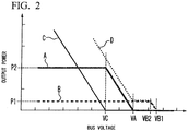
- FIG. 2 is a graph showing an example of the energy management method for a charging facility according to the embodiment of the invention.
- FIG. 2 includes four graphs in total of a first graph (A) to a fourth graph (D).
- the vertical axis indicates the voltage of the DC bus 1
- the horizontal axis indicates output power of the DC bus 1.
- the first graph (A) indicates the relationship between power supplied from the AC/DC conversion circuit 10 for a system power supply to the DC bus 1 and the voltage of the DC bus 1.
- the second graph (B) indicates the relationship between power supplied from the DC/DC conversion circuit 22 for a power generation device to the DC bus 1 and the voltage of the DC bus 1.
- the third graph (C) indicates the relationship between power supplied from the DC/DC conversion circuit 32 for a storage device to the DC bus 1 and the voltage of the DC bus 1.
- the fourth graph (D) indicates the relationship between a load applied from the DC/DC conversion circuit 42 for a charging device to the DC bus 1 to the voltage of the DC bus 1.
- P1 is maximum output power determined by the rating of the DC/DC conversion circuit 22 for a power generation device
- P2 is an upper limit set value of power received from the AC/DC conversion circuit 10 for a system power supply.
- VA is a set voltage for a system power supply
- VB1 is a first set voltage for a power generation device
- VB2 is a second set voltage for a power generation device
- VC is a set voltage for a storage device.
- the set voltage VA for a system power supply is set in the AC/DC converter control circuit 13 for a system power supply of the AC/DC conversion circuit 10 for a system power supply.
- the first set voltage VB1 for a power generation device and the second set voltage VB2 for a power generation device are set in the DC/DC converter control circuit 23 for a power generation device of the power generation system.
- the set voltage VC for a storage device is set in the DC/DC converter control circuit 33 for a storage device of the storage system.
- the set voltage VC for a storage device is set to be lower than the set voltage VA for a system power supply
- the set voltage VA for a system power supply is set to be lower than the second set voltage VB2 for a power generation device
- the second set voltage VB2 for a power generation device is set to be lower than the first set voltage VB 1 for a power generation device.
- the AC/DC converter control circuit 13 for a system power supply continuously monitors the voltage of the DC bus 1, and if the voltage of the DC bus 1 exceeds the set voltage VA for a system power supply, the AC/DC converter control circuit 13 for a system power supply controls the AC/DC converter motor circuit 14 for a system power supply and stops power supply from the AC/DC conversion circuit 10 for a system power supply to the DC bus 1. On the contrary, if the voltage of the DC bus 1 falls below the set voltage VA for a system power supply, the AC/DC converter control circuit 13 for a system power supply controls the AC/DC converter motor circuit 14 for a system power supply and supplies power from the system power supply 60 to the DC bus 1.
- the DC/DC converter control circuit 23 for a power generation device continuously monitors the voltage of the DC bus 1, and if the voltage of the DC bus 1 exceeds the first set voltage VB1 for a power generation device, the DC/DC converter control circuit 23 for a power generation device controlling stopping power supply to the DC bus 1 of the DC/DC converter motor circuit 24 for a power generation device. On the contrary, if the voltage of the DC bus 1 falls below the first set voltage VB1 for a power generation device, the DC/DC converter control circuit 23 for a power generation device controlling starting of the operation of the DC/DC converter motor circuit 24 for a power generation device.
- the DC/DC converter control circuit 33 for a storage device continuously monitors the voltage of the DC bus 1, and if the voltage of the DC bus 1 exceeds the set voltage VC for a storage device, the DC/DC converter control circuit 33 for a storage device controlling stopping of the power supply to the DC bus 1 of the DC/DC converter motor circuit 34 for a storage device. On the contrary, if the voltage of the DC bus 1 falls below the set voltage VC for a storage device, the DC/DC converter control circuit 33 for a storage device controlling starting of the discharging operation of the DC/DC converter motor circuit 34 for a storage device.
- the charging facility is activated from a state where the voltage of the DC bus 1 is zero as an initial condition. From this state, the AC/DC conversion circuit 10 for a system power supply starts to operate, and increases the voltage of the DC bus 1 to be stabilized at the set voltage VA for a system power supply. Thereafter, the power generation system and the storage system start to operate. In a case where the amount of charge of the fixed storage battery 31 reaches an upper limit, the voltage of the DC bus 1 increases with generated power of the power generation system, and if the voltage of the DC bus 1 exceeds the first set voltage VB1 for a power generation device, the power generation system stops power supply to the DC bus 1.
- the on-board rechargeable battery 52 of the electric vehicle 50 is connected to the rechargeable battery 41 through the on-board charging circuit 51, and if charging of the fixed storage battery 31 starts, a load applied to the DC bus 1 increases, and when the load increases, the voltage of the DC bus 1 decreases.
- the DC/DC converter control circuit 23 for a power generation device which monitors the voltage of the DC bus 1 detects this state, and performs control such that the DC/DC converter motor circuit 24 for a power generation device starts to operate.
- the DC/DC converter motor circuit 24 for a power generation device receives DC power generated by solar power generation of the solar power generation module 21, converts the DC voltage of power, and supplies power to the DC bus 1. Since the presence or absence of supply or the supply amount of generated power to the DC bus 1 is determined by the DC/DC conversion circuit 22 for a power generation device based on the voltage of the DC bus 1, the solar power generation module 21 may continuously continue solar power generation without particular control.
- Generated power supplied from the power generation system to the DC bus 1 increases when the voltage of the DC bus 1 decreases. Generated power of the power generation system reaches maximum generated power of the power generation device when the voltage of the DC bus 1 decreases and reaches the second set voltage VB2 for a power generation device.
- the AC/DC converter control circuit 13 for a system power supply which monitors the voltage of the DC bus 1 detects this state, and the AC/DC converter motor circuit 14 for a system power supply starts power supply to the DC bus 1.
- the AC/DC converter motor circuit 14 for a system power supply receives AC power of a system from the system power supply 60.
- the AC/DC converter motor circuit 14 for a system power supply converts input AC power to DC power and supplies DC power to the DC bus 1.
- Power supplied from the AC/DC conversion circuit 10 for a system power supply to the DC bus 1 increases when the voltage of the DC bus 1 decreases.
- a voltage that the voltage of the DC bus 1 reaches is set in the DC/DC converter control circuit 33 for a storage device as the set voltage VC for a storage device.
- the set voltage VC for a storage device is set such that output power from the AC/DC conversion circuit 10 for a system power supply reaches the maximum power P2, and the storage system starts power supply to the DC bus 1.
- the DC/DC converter control circuit 33 for a storage device which monitors the voltage of the DC bus 1 detects this state, and performs control such that the DC/DC converter motor circuit 34 for a storage device starts the discharging operation.
- the DC/DC converter motor circuit 34 for a storage device receives DC power charged in advance in the fixed storage battery 31, changes the voltage of DC power, and supplies DC power to the DC bus 1. That is, DC power discharged from the fixed storage battery 31 is supplied to the DC bus 1 through the DC/DC converter motor circuit 34 for a storage device.
- charging of the on-board rechargeable battery 52 is performed with the total sum of the maximum power P1 which can be supplied from the power generation system, the maximum power P2 which can be supplied from the AC/DC conversion circuit 10 for a system power supply, and discharging power supplied from the storage system.
- the set voltage VA for a system power supply, the first set voltage VB1 for a power generation device, the second set voltage VB2 for a power generation device, and the set voltage VC for a storage device, the inclination of the graph representing the relationship between power and the voltage of the DC bus 1 set in each of the AC/DC conversion circuit 10 for a system power supply, the power generation system, and the storage system, and the like can be adjusted within a predetermined range in the AC/DC converter control circuit 13 for a system power supply, the DC/DC converter control circuit 23 for a power generation device, the DC/DC converter control circuit 33 for a storage device, and the like.
- the adjustment is appropriately performed, whereby it is possible to freely determine the priority of the respective power converters which supply power to the load applied to the DC bus 1.
- a charging operation of the fixed storage battery 31 in the storage system will be described. While the voltage of the DC bus 1 has a value higher than the set voltage VC for a storage device, that is, while the fixed storage battery 31 is not discharging, charging of the fixed storage battery 31 can be performed in parallel with charging of the on-board rechargeable battery 52.
- Charging of the fixed storage battery 31 can be performed in two operation modes. First, in a case where the remaining amount of charge of the fixed storage battery 31 is equal to or greater than a predetermined reference amount of charge set in advance, for example, equal to or greater than 50%, charging is performed only with power supplied from the power generation system without using power of the AC/DC conversion circuit 10 for a system power supply. The determination is performed by the storage battery state monitoring device 36 monitoring the remaining amount of charge of the storage battery cell 35.
- charging is performed in a short period of time using power supplied from the AC/DC conversion circuit 10 for a system power supply as well as power supplied from the power generation system. At this time, power supplied from the system power supply 60 is equal to or less than the upper limit set value of received power.
- the DC/DC converter control circuit 33 for a storage device controlling stopping of the power supply to both of the fixed storage battery 31 and the DC bus 1 of the DC/DC converter motor circuit 34 for a storage device.
- FIG. 3 is a graph showing another example of the energy management method for a charging facility according to the embodiment of the invention.
- the graph shown in FIG. 3 includes a first graph (A) and a second graph (B).
- the horizontal axis indicates time
- the vertical axis indicates power supply-side power.
- the first graph (A) indicates an example of variation with time in power supplied from the DC bus 1 to the on-board rechargeable battery 52 of the electric vehicle 50.
- the second graph (B) indicates an example of variation with time in power supplied from the DC bus 1 to the fixed storage battery 31.
- a period from the time t0 to the time t2 indicates a period during which the voltage of the DC bus 1 is higher than the set voltage VA for a system power supply and equal to or lower than the first set voltage VB1 for a power generation device.
- a period from the time t2 to the time t3 indicates a period during which the voltage of the DC bus 1 is higher than the set voltage VC for a storage device and equal to or lower than the set voltage VA for a system power supply.
- a period from the time t3 to the time t5 is a period during which the voltage of the DC bus 1 is equal to or lower than the set voltage VC for a storage device.
- a period from the time t5 to the time t7 is a period during which the voltage of the DC bus 1 is equal to the set voltage VC for a storage device.
- a period from the time t7 to the time t8 is a period during which the voltage of the DC bus 1 is equal to the set voltage VA for a system power supply.
- a period from the time t8 to the time t9 is a period during which the voltage of the DC bus 1 is equal to or higher than the set voltage VA for a system power supply and equal to or lower than the first set voltage VB1 for a power generation device.
- the set voltage VA for a system power supply, the first set voltage VB1 for a power generation device, and the set voltage VC for a storage device are the same as those in the description relating to FIG. 2 .
- power P1 indicates maximum power which can be supplied from the power generation system.
- Power P2 indicates the total sum of maximum power which can be supplied from the power generation system and maximum power which can be supplied from the AC/DC conversion circuit 10 for a system power supply.
- Power P3 indicates the total sum of maximum power which can be supplied from the power generation system, maximum power which can be supplied from the AC/DC conversion circuit 10 for a system power supply, and maximum power which can be supplied at the time of discharging the storage system.
- the maximum power which can be supplied from each of the AC/DC conversion circuit 10 for a system power supply, the power generation system, and the storage system is the same as that in the description relating to FIG. 2 .
- the storage battery cell 35 is charged to an upper limit of capacity.
- the voltage of the DC bus 1 is higher than the set voltage VA for a system power supply and equal to or lower than the first set voltage VB1 for a power generation device.
- charging of the electric vehicle 50 starts. Thereafter, at the time t2, until the power supply-side power reaches the power P1, charging of the electric vehicle 50 is performed with power supplied from the DC/DC conversion circuit 22 for a power generation device to the DC bus 1 according to the voltage of the DC bus 1. From the time t1 to the time t2, the voltage of the DC bus 1 is higher than the set voltage VA for a system power supply and equal to or lower than the first set voltage VB1 for a power generation device.
- the supply-side power reaches the power P1. Charging of the electric vehicle 50 continues and is performed by the maximum generated power of the DC/DC conversion circuit 22 for a power generation device and received power from the system power supply 60.
- the supply-side power continues to increase and reaches power P2 at the time t3. From the time t2 to the time t3 during which the supply-side power is equal to or greater than the power P1 and less than the power P2, the voltage of the DC bus 1 is higher than the set voltage VC for a storage device and equal to or lower than the set voltage VA for a system power supply.
- the supply-side power reaches the power P2.
- Charging of the electric vehicle 50 continues and is performed with the maximum generated power of the DC/DC conversion circuit 22 for a power generation device, the upper limit value of received power from the system power supply 60, and discharging power of the DC/DC conversion circuit 32 for a storage device.
- discharging power of the DC/DC conversion circuit 32 for a storage device is determined according to the voltage of the DC bus 1.
- the supply-side power continues to increase and reaches power P3 at the time t4. From the time t3 to the time t4 during which the supply-side power is equal to or greater than the power P2 and less than the power P3, the voltage of the DC bus 1 is equal to or lower than the set voltage VC for a storage device.
- the supply-side power reaches the power P3. While charging of the electric vehicle 50 continues and is performed with the maximum generated power of the DC/DC conversion circuit 22 for a power generation device, the upper limit value of received power from the system power supply 60, and discharging power of the DC/DC conversion circuit 32 for a storage device, the amount of charge of the electric vehicle 50 approaches a full charge state, charging power is started to be restricted. Thereafter, at the time t5, the supply-side power reaches the power P2. From the time t4 to the time t5 during which the supply-side power is equal to or less than the power P3 and greater than the power P2, the voltage of the DC bus 1 is equal to or lower than the set voltage VC for a storage device.
- the supply-side power reaches the power P2. While charging of the electric vehicle 50 continues, the amount of charge of the electric vehicle 50 further approaches the full charge state, and charging power is restricted.
- the supply-side power is less than the power P2 and equal to or greater than the power P1
- the DC/DC conversion circuit 32 for a storage device discharges, and the amount of charge decreases, the electric vehicle 50 and the storage battery cell 35 are charged with the maximum generated power of the DC/DC conversion circuit 22 for a power generation device and received power from the system power supply 60. Thereafter, at the time t6, charging of the electric vehicle 50 ends.
- the voltage of the DC bus 1 is equal to the set voltage VC for a storage device.
- Charging power of the storage battery cell 35 is controlled by the DC/DC converter control circuit 33 for a storage device which monitors the voltage of the DC bus 1 such that the voltage of the DC bus 1 does not fall below the set voltage VC for a storage device.
- charging of the electric vehicle 50 ends.
- the storage battery cell 35 is discharged and the amount of charge decreases, the storage battery cell 35 is charged with the maximum generated power of the DC/DC conversion circuit 22 for a power generation device and received power from the system power supply 60.
- Charging power of the storage battery cell 35 is controlled by the DC/DC converter control circuit 33 for a storage device which monitors the voltage of the DC bus 1 such that the voltage of the DC bus 1 does not fall below the set voltage VC for a storage device.
- the amount of charge of the storage battery cell 35 reaches a value set in advance. Thereafter, until the time t8 when the amount of charge of the storage battery cell 35 approaches the full charge state, charging of the storage battery cell 35 is performed only with the maximum generated power of the DC/DC conversion circuit 22 for a power generation device. From the time t7 to the time t8, the voltage of the DC bus 1 is equal to the set voltage VA for a system power supply.
- the DC/DC conversion circuit 32 for storage device starts to restrict charging power. For this reason, the voltage of the DC bus 1 increases, and power supply from the DC/DC conversion circuit 22 for a power generation device is restricted. Thereafter, at the time t9, while the amount of charge of the storage battery cell 35 reaches the full charge state, the voltage of the DC bus 1 is higher than the set voltage VA for a system power supply and equal to or lower than the first set voltage VB1 for a power generation device.
- the charging facility and the energy management method for a charging facility according to the embodiment of the invention described above have the following features.
- each of the AC/DC conversion circuit 10 for a system power supply, the DC/DC conversion circuit 22 for a power generation device, and the DC/DC conversion circuit 32 for a storage device autonomously performs an independent operation under automatic control only based on the voltage fluctuating in the DC bus 1. Accordingly, an upper-level control device which manages the entire charging facility is not required, and the configuration as the whole of the charging facility is simplified.
- the charging facility according to the invention allows very flexible operation.
Landscapes
- Engineering & Computer Science (AREA)
- Power Engineering (AREA)
- Transportation (AREA)
- Mechanical Engineering (AREA)
- Charge And Discharge Circuits For Batteries Or The Like (AREA)
- Electric Propulsion And Braking For Vehicles (AREA)
Abstract
Description
- The present invention relates to a fast charging facility for an electric vehicle linked with a power generation device, such as a solar power generation module, or a charging/discharging device, such as a fixed storage battery, and can be suitably applied to an energy management method for each device associated with the charging facility.
- At the time of fast charging of an electric vehicle, power which is consumed at the time of traveling of the electric vehicle should be supplied in a comparatively short charging time. In other words, a large load is applied to a so-called system power supply, that is, a power facility which supplies commercial power, in inverse proportion to the shortness of the charging time of the electric vehicle.
- In addition, since the time zone during which fast charging of the electric vehicle is required depends on the life pattern of a driver, hereafter, if the electric vehicles become more popular, fast charging may be intensively performed according to the season, a day of the week, a time zone, or the like. Accordingly, controlling smoothing power demand for a short period of time due to fast charging and limiting the power demand peak for a system power supply is required.
- As a method therefor, a technique in which each of a plurality of devices including a power generation device, such as a solar power generation device, or a storage device, such as a fixed storage battery, in addition to the system power supply are used in combination is known.
- In relation to the above, PTL 1 (
WO2011/162025 ) discloses a technique relating to a DC power distribution system. The DC power distribution system described in PTL 1 includes a DC power distribution system, a first power conversion device, a second power conversion device, and a third power conversion device. The DC power distribution system supplies DC power to a load device. The first power conversion device performs voltage conversion of generated power of a solar power generation device and supplies power to the DC power distribution system. The second power conversion device performs voltage conversion between a first power storage device always connected to the DC power distribution system and the DC power distribution system, and supplies power from one side to the other side. The third power conversion device performs power conversion between an AC system and the DC power distribution system, and supplies power from one side to the other side. The DC power distribution system includes an operation mode setting unit and an operation control unit. The operation mode setting unit determines an operation mode according to operation mode determination information for setting an operation mode of the DC power distribution system. The operation control unit sets a first control parameter for the second power conversion device and a second control parameter for the third power conversion device according to the operation mode set by the operation mode setting unit. The second power conversion device performs control of a power supply direction, operation start, and operation stop according to the voltage of the DC power distribution system and the first control parameter. The third power conversion device performs control of a power supply direction, operation start, and operation stop according to the voltage of the DC power distribution system and the second control parameter. - In the DC power distribution system described in PTL 1, first, a storage device of a charging facility is charged with power supplied from a plurality of power supply devices, and then, power charged in the storage device is discharged to charge the electric vehicle. For this end, it is necessary to appropriately control the timing at which the storage device is charged or discharged, the timing at which a plurality of power supply devices, such as a system power supply or a power generation device, supply power to a storage battery, or the like.
- [PTL 1]
WO2011/162025 - The invention provides a fast charging facility for an electric vehicle which has a simple configuration and allows flexible operation while a power generation device and a storage device are combined with a system power supply, and an energy management method for the charging facility.
- Other objects and novel features will become apparent from the description of this specification and the accompanying drawings.
- According to one embodiment, a charging facility transforms power supplied from a plurality of power supply devices and a storage device with power converters, collects power in a DC bus, and then, uses power to charge an electric vehicle. In an energy management method for a charging facility, each power converter operates under independent automatic control according to a change in voltage in the DC bus.
- According to one embodiment described above, an upper-level control unit which collectively controls a plurality of power supply sources is not required, a plurality of power supply devices can be combined with a simple configuration achieved by merely connecting respective output terminals to the DC bus. In addition, the entire charging facility can be operated flexibly.
-
-
FIG. 1 is a block circuit diagram showing a configuration example of a charging facility according to an embodiment of the invention. -
FIG. 2 is a graph showing an example of an energy management method for a charging facility according to an embodiment of the invention. -
FIG. 3 is a graph showing another example of an energy management method for a charging facility according to an embodiment of the invention. - A mode for carrying out a charging facility and an energy management method for a charging facility according to the invention will be described below referring to the accompanying drawings.
- In an embodiment of the invention, one configuration example of a charging facility in which a plurality of power converters are connected to a DC bus will be described.
- Each of a plurality of power converters can be broadly classified into three types. The power converters included in the first classification convert AC power supplied from the outside, such as a system power supply, to DC power and supply the DC power to the DC bus. The power converter included in the second classification supply power generated by a power generation device, such as a solar power generation module, to the DC bus. The power converters included in the third classification receive power from the DC bus to charge the storage device. The power converters included in the third classification also discharge power charged in the storage device and supply power to the DC bus.
- The charging facility described herein is connected to a system power supply, and has one power generation device and one storage device. However, the number of devices is just an example, and is not intended to limit the invention. the details will be described below, the presence or absence of connection to the system power supply, or the number of connected power generation devices or storage devices is not particularly limited, and in some cases, even if any one of the system power supply, the power generation device, and the storage device is not linked, operation can be continued by a combination of the remaining devices.
-
FIG. 1 is a block circuit diagram showing a configuration example of the charging facility according to the embodiment of the invention. The components of the charging facility shown inFIG. 1 will be described. - The charging facility shown in
FIG. 1 includes a DC bus 1, an alternative current (AC)/direct current (DC)conversion circuit 10 for a system power supply which receives power from asystem power supply 60, a solarpower generation module 21, a DC/DC conversion circuit 22 for a power generation device, afixed storage battery 31, a DC/DC conversion circuit 32 for a storage device, arechargeable battery 41, and a DC/DC conversion circuit 42 for a charging device for use in an electric vehicle. - The AC/
DC conversion circuit 10 for a system power supply which receives power from thesystem power supply 60 and converts power to a DC voltage includes an AC/DCconverter control circuit 13 for a system power supply and an AC/DCconverter motor circuit 14 for a system power supply. The DC/DC conversion circuit 22 for a power generation device includes a DC/DC converter control circuit 23 for a power generation device and a DC/DCconverter motor circuit 24 for a power generation device. The DC/DC conversion circuit 22 for a power generation device and the solarpower generation module 21 may be collectively referred to as a power generation system. - The DC/
DC conversion circuit 32 for a storage device includes a DC/DC converter control circuit 33 for a storage device and a DC/DCconverter motor circuit 34 for a storage device. Thefixed storage battery 31 includes astorage battery cell 35 and a storage batterystate monitoring device 36. The DC/DC conversion circuit 32 for a storage device and thefixed storage battery 31 may be collectively referred to as a storage system. The DC/DC conversion circuit 42 for a charging device includes a DC/DCconverter control circuit 43 for a charging device and a DC/DCconverter motor circuit 44 for a charging device. The DC/DC conversion circuit 42 for a charging device and therechargeable battery 41 may be collectively referred to as a charging system. The motor circuit of each conversion circuit functions as a DC power generation device which generates DC power. -
FIG. 1 also shows anelectric vehicle 50, an on-board charging circuit 51, an on-boardrechargeable battery 52, and asystem power supply 60. The on-board charging circuit 51 and the on-boardrechargeable battery 52 are included in theelectric vehicle 50. - Though not shown in
FIG. 1 , the DC bus 1 includes a positive voltage bus to which a positive voltage is applied, and a negative voltage bus to which a negative voltage is applied. This configuration is just an example, and for example, a ground may be used instead of the negative bus. The solarpower generation module 21 is just an example, and for example, a wind power generation module may be used instead. - The functions of the components of the charging facility shown in
FIG. 1 will be described. Power received from thesystem power supply 60 is converted from an AC voltage to a DC voltage by the AC/DC conversion circuit 10 for a system power supply, and is supplied to the DC bus 1. - The power generation system transforms (DC/DC conversion) power generated by the solar
power generation module 21 with the DC/DC conversion circuit 22 for a power generation device, and supplies power to the DC bus 1. - In regard to the storage system, charging power is supplied from the DC bus 1 to the fixed
storage battery 31 by the DC/DC conversion circuit 32 for a storage device, and discharging power is supplied from the fixedstorage battery 31 to the DC bus 1. - In regard to the charging system, power requested by the on-
board charging circuit 51 is supplied from the DC bus 1 according to the remaining amount of the on-boardrechargeable battery 52 of theelectric vehicle 50, thereby charging the on-boardrechargeable battery 52. - The operation of the charging facility according to the embodiment of the invention, that is, the energy management method for a charging facility according to the embodiment of the invention will be described in more detail.
- The charging facility and the energy management method for a charging facility according to the embodiment of the invention have the following three features. The first feature is that peak cutting of received power from the
system power supply 60 can be performed without limiting charging power to theelectric vehicle 50. Peak cutting of received power is performed, whereby it is possible to reduce a basic charge of electricity charges. The second feature is that the most of renewable energy, such as power by solar power generation, is usable. The third feature is that power loss in the power converters can be reduced. - Accordingly, in the embodiment of the invention, charging of the on-board
rechargeable battery 52 is performed with the following priority. That is, first, power supplied from the power generation system is used. If power supplied from the power generation system is insufficient, power supplied from thesystem power supply 60 is additionally used. In order to realize peak cutting of system received power, an upper limit value is set for power received from thesystem power supply 60. For this reason, if power supplied from the power generation system and thesystem power supply 60 is yet insufficient, power supplied by discharging of the storage system is additionally used. - In the embodiment of the invention, charging of the storage system is performed using the following priority. That is, in a case where the remaining amount of charge of the fixed
storage battery 31 has some margin, charging of the fixedstorage battery 31 is performed only using power supplied from the power generation system. In a case where the remaining amount of charge of the fixedstorage battery 31 is smaller than a predetermined reference value, charging of the fixedstorage battery 31 is performed in a short period of time using power supplied from thesystem power supply 60 in combination with power supplied from the power generation system. - The above control is performed by the respective power converters of the
system power supply 60, the power generation system, the storage system, and the charging system individually, that is, independently from other power converters. Specifically, for example, the AC/DCconverter control circuit 13 for a system power supply monitors the voltage of the DC bus 1, and the AC/DCconverter control circuit 13 for a system power supply controls the operation of the AC/DCconverter motor circuit 14 for a system power supply based on the result of monitoring, whereby the operation of the AC/DC conversion circuit 10 for a system power supply connected to thesystem power supply 60 is performed. At this time, control which is performed by the AC/DCconverter control circuit 13 for a system power supply has no relation to the power generation system, the storage system, and the charging system. The same applies to the operation of the power generation system, the storage system, and the charging system. - In other words, the charging facility according to the invention collects power supplied from the AC/
DC conversion circuit 10 for a system power supply, the power generation system, and the storage system in the DC bus 1 in the form of DC power, and charges the on-boardrechargeable battery 52 of theelectric vehicle 50 with DC power collected in the DC bus 1. In the charging facility according to the invention, controlling fixing the DC voltage in the DC bus 1 is not performed, and fluctuation of the DC voltage in the DC bus 1 is used as a trigger on which the AC/DC conversion circuit 10 for a system power supply, the power generation system, the storage system, and the charging system perform automatic control individually. - An example of the overall operation of the charging facility shown in
FIG. 1 will be described referring toFIG. 2. FIG. 2 is a graph showing an example of the energy management method for a charging facility according to the embodiment of the invention. -
FIG. 2 includes four graphs in total of a first graph (A) to a fourth graph (D). In each of the first graph (A) to the fourth graph (D), the vertical axis indicates the voltage of the DC bus 1, and the horizontal axis indicates output power of the DC bus 1. - The first graph (A) indicates the relationship between power supplied from the AC/
DC conversion circuit 10 for a system power supply to the DC bus 1 and the voltage of the DC bus 1. The second graph (B) indicates the relationship between power supplied from the DC/DC conversion circuit 22 for a power generation device to the DC bus 1 and the voltage of the DC bus 1. The third graph (C) indicates the relationship between power supplied from the DC/DC conversion circuit 32 for a storage device to the DC bus 1 and the voltage of the DC bus 1. The fourth graph (D) indicates the relationship between a load applied from the DC/DC conversion circuit 42 for a charging device to the DC bus 1 to the voltage of the DC bus 1. - In the vertical axis of the graph shown in
FIG. 2 , P1 is maximum output power determined by the rating of the DC/DC conversion circuit 22 for a power generation device, and P2 is an upper limit set value of power received from the AC/DC conversion circuit 10 for a system power supply. - In the horizontal axis of the graph shown in
FIG. 2 , VA is a set voltage for a system power supply, VB1 is a first set voltage for a power generation device, VB2 is a second set voltage for a power generation device, and VC is a set voltage for a storage device. The set voltage VA for a system power supply is set in the AC/DCconverter control circuit 13 for a system power supply of the AC/DC conversion circuit 10 for a system power supply. The first set voltage VB1 for a power generation device and the second set voltage VB2 for a power generation device are set in the DC/DC converter control circuit 23 for a power generation device of the power generation system. The set voltage VC for a storage device is set in the DC/DC converter control circuit 33 for a storage device of the storage system. In the example ofFIG. 2 , the set voltage VC for a storage device is set to be lower than the set voltage VA for a system power supply, the set voltage VA for a system power supply is set to be lower than the second set voltage VB2 for a power generation device, and the second set voltage VB2 for a power generation device is set to be lower than the first set voltage VB 1 for a power generation device. - Specifically, for example, in the AC/
DC conversion circuit 10 for a system power supply, the AC/DCconverter control circuit 13 for a system power supply continuously monitors the voltage of the DC bus 1, and if the voltage of the DC bus 1 exceeds the set voltage VA for a system power supply, the AC/DCconverter control circuit 13 for a system power supply controls the AC/DCconverter motor circuit 14 for a system power supply and stops power supply from the AC/DC conversion circuit 10 for a system power supply to the DC bus 1. On the contrary, if the voltage of the DC bus 1 falls below the set voltage VA for a system power supply, the AC/DCconverter control circuit 13 for a system power supply controls the AC/DCconverter motor circuit 14 for a system power supply and supplies power from thesystem power supply 60 to the DC bus 1. - Similarly, in the power generation system, the DC/DC converter control circuit 23 for a power generation device continuously monitors the voltage of the DC bus 1, and if the voltage of the DC bus 1 exceeds the first set voltage VB1 for a power generation device, the DC/DC converter control circuit 23 for a power generation device controlling stopping power supply to the DC bus 1 of the DC/DC
converter motor circuit 24 for a power generation device. On the contrary, if the voltage of the DC bus 1 falls below the first set voltage VB1 for a power generation device, the DC/DC converter control circuit 23 for a power generation device controlling starting of the operation of the DC/DCconverter motor circuit 24 for a power generation device. When the voltage of the DC bus 1 decreases from VB1, power supplied from the power generation system to the DC bus 1 increases, and maximum generated power is supplied at a voltage equal to or lower than VB2. In the storage system, the DC/DC converter control circuit 33 for a storage device continuously monitors the voltage of the DC bus 1, and if the voltage of the DC bus 1 exceeds the set voltage VC for a storage device, the DC/DC converter control circuit 33 for a storage device controlling stopping of the power supply to the DC bus 1 of the DC/DCconverter motor circuit 34 for a storage device. On the contrary, if the voltage of the DC bus 1 falls below the set voltage VC for a storage device, the DC/DC converter control circuit 33 for a storage device controlling starting of the discharging operation of the DC/DCconverter motor circuit 34 for a storage device. - In the example of
FIG. 2 , first, the charging facility is activated from a state where the voltage of the DC bus 1 is zero as an initial condition. From this state, the AC/DC conversion circuit 10 for a system power supply starts to operate, and increases the voltage of the DC bus 1 to be stabilized at the set voltage VA for a system power supply. Thereafter, the power generation system and the storage system start to operate. In a case where the amount of charge of the fixedstorage battery 31 reaches an upper limit, the voltage of the DC bus 1 increases with generated power of the power generation system, and if the voltage of the DC bus 1 exceeds the first set voltage VB1 for a power generation device, the power generation system stops power supply to the DC bus 1. That is, in a state where the voltage of the DC bus 1 exceeds the first set voltage VB 1 for a power generation device, since the first set voltage VB 1 for a power generation device is set to be higher than the set voltage VA for a system power supply and the set voltage VC for a storage device, controlling stopping of the entire power supply to the DC bus 1 is performed. - Next, the on-board
rechargeable battery 52 of theelectric vehicle 50 is connected to therechargeable battery 41 through the on-board charging circuit 51, and if charging of the fixedstorage battery 31 starts, a load applied to the DC bus 1 increases, and when the load increases, the voltage of the DC bus 1 decreases. - If the voltage of the DC bus 1 falls below the first set voltage VB1 for a power generation device, the DC/DC converter control circuit 23 for a power generation device which monitors the voltage of the DC bus 1 detects this state, and performs control such that the DC/DC
converter motor circuit 24 for a power generation device starts to operate. - If the operation starts, the DC/DC
converter motor circuit 24 for a power generation device receives DC power generated by solar power generation of the solarpower generation module 21, converts the DC voltage of power, and supplies power to the DC bus 1. Since the presence or absence of supply or the supply amount of generated power to the DC bus 1 is determined by the DC/DC conversion circuit 22 for a power generation device based on the voltage of the DC bus 1, the solarpower generation module 21 may continuously continue solar power generation without particular control. - Hereinafter, until the voltage of the DC bus 1 reaches the set voltage VA for a system power supply, charging of the on-board
rechargeable battery 52 is performed with power supplied from the power generation system to the DC bus 1. - Generated power supplied from the power generation system to the DC bus 1 increases when the voltage of the DC bus 1 decreases. Generated power of the power generation system reaches maximum generated power of the power generation device when the voltage of the DC bus 1 decreases and reaches the second set voltage VB2 for a power generation device.
- If the voltage of the DC bus 1 decreases and reaches the set voltage VA for a system power supply, the AC/DC
converter control circuit 13 for a system power supply which monitors the voltage of the DC bus 1 detects this state, and the AC/DCconverter motor circuit 14 for a system power supply starts power supply to the DC bus 1. - The AC/DC
converter motor circuit 14 for a system power supply receives AC power of a system from thesystem power supply 60. The AC/DCconverter motor circuit 14 for a system power supply converts input AC power to DC power and supplies DC power to the DC bus 1. - Hereinafter, until the voltage of the DC bus 1 reaches the set voltage VC for a storage device, charging of the on-board
rechargeable battery 52 is performed with the total sum of power supplied from the power generation system and the AC/DC conversion circuit 10 for a system power supply to the DC bus 1. - Power supplied from the AC/
DC conversion circuit 10 for a system power supply to the DC bus 1 increases when the voltage of the DC bus 1 decreases. In this example, when power output from the AC/DC conversion circuit 10 for a system power supply reaches the maximum power P2 which is an upper limit set value of received power, a voltage that the voltage of the DC bus 1 reaches is set in the DC/DC converter control circuit 33 for a storage device as the set voltage VC for a storage device. In other words, the set voltage VC for a storage device is set such that output power from the AC/DC conversion circuit 10 for a system power supply reaches the maximum power P2, and the storage system starts power supply to the DC bus 1. - If the voltage of the DC bus 1 decreases and reaches the set voltage VC for a storage device, the DC/DC converter control circuit 33 for a storage device which monitors the voltage of the DC bus 1 detects this state, and performs control such that the DC/DC
converter motor circuit 34 for a storage device starts the discharging operation. - If the discharging operation starts, the DC/DC
converter motor circuit 34 for a storage device receives DC power charged in advance in the fixedstorage battery 31, changes the voltage of DC power, and supplies DC power to the DC bus 1. That is, DC power discharged from the fixedstorage battery 31 is supplied to the DC bus 1 through the DC/DCconverter motor circuit 34 for a storage device. - Hereinafter, while the voltage of the DC bus 1 is lower than the set voltage VC for a storage device, charging of the on-board
rechargeable battery 52 is performed with the total sum of the maximum power P1 which can be supplied from the power generation system, the maximum power P2 which can be supplied from the AC/DC conversion circuit 10 for a system power supply, and discharging power supplied from the storage system. - The set voltage VA for a system power supply, the first set voltage VB1 for a power generation device, the second set voltage VB2 for a power generation device, and the set voltage VC for a storage device, the inclination of the graph representing the relationship between power and the voltage of the DC bus 1 set in each of the AC/
DC conversion circuit 10 for a system power supply, the power generation system, and the storage system, and the like can be adjusted within a predetermined range in the AC/DCconverter control circuit 13 for a system power supply, the DC/DC converter control circuit 23 for a power generation device, the DC/DC converter control circuit 33 for a storage device, and the like. The adjustment is appropriately performed, whereby it is possible to freely determine the priority of the respective power converters which supply power to the load applied to the DC bus 1. - A charging operation of the fixed
storage battery 31 in the storage system will be described. While the voltage of the DC bus 1 has a value higher than the set voltage VC for a storage device, that is, while the fixedstorage battery 31 is not discharging, charging of the fixedstorage battery 31 can be performed in parallel with charging of the on-boardrechargeable battery 52. - Charging of the fixed
storage battery 31 can be performed in two operation modes. First, in a case where the remaining amount of charge of the fixedstorage battery 31 is equal to or greater than a predetermined reference amount of charge set in advance, for example, equal to or greater than 50%, charging is performed only with power supplied from the power generation system without using power of the AC/DC conversion circuit 10 for a system power supply. The determination is performed by the storage batterystate monitoring device 36 monitoring the remaining amount of charge of thestorage battery cell 35. - Next, in a case where it is determined that the remaining amount of charge of the fixed
storage battery 31 is smaller than the reference amount of charge, for example, less than 50%, charging is performed in a short period of time using power supplied from the AC/DC conversion circuit 10 for a system power supply as well as power supplied from the power generation system. At this time, power supplied from thesystem power supply 60 is equal to or less than the upper limit set value of received power. - In a case where the amount of charge of the fixed
storage battery 31 reaches the upper limit value and where the voltage of the DC bus 1 is equal to or higher than the set voltage VC for a storage device, the DC/DC converter control circuit 33 for a storage device controlling stopping of the power supply to both of the fixedstorage battery 31 and the DC bus 1 of the DC/DCconverter motor circuit 34 for a storage device. - Another example of the overall operation of the charging facility shown in
FIG. 1 will be described referring toFIG. 3. FIG. 3 is a graph showing another example of the energy management method for a charging facility according to the embodiment of the invention. - The graph shown in
FIG. 3 includes a first graph (A) and a second graph (B). In each of the first graph (A) and the second graph (B), the horizontal axis indicates time, and the vertical axis indicates power supply-side power. - The first graph (A) indicates an example of variation with time in power supplied from the DC bus 1 to the on-board
rechargeable battery 52 of theelectric vehicle 50. The second graph (B) indicates an example of variation with time in power supplied from the DC bus 1 to the fixedstorage battery 31. - In the horizontal axis of the graph shown in
FIG. 3 , a period from the time t0 to the time t2 indicates a period during which the voltage of the DC bus 1 is higher than the set voltage VA for a system power supply and equal to or lower than the first set voltage VB1 for a power generation device. A period from the time t2 to the time t3 indicates a period during which the voltage of the DC bus 1 is higher than the set voltage VC for a storage device and equal to or lower than the set voltage VA for a system power supply. A period from the time t3 to the time t5 is a period during which the voltage of the DC bus 1 is equal to or lower than the set voltage VC for a storage device. A period from the time t5 to the time t7 is a period during which the voltage of the DC bus 1 is equal to the set voltage VC for a storage device. A period from the time t7 to the time t8 is a period during which the voltage of the DC bus 1 is equal to the set voltage VA for a system power supply. A period from the time t8 to the time t9 is a period during which the voltage of the DC bus 1 is equal to or higher than the set voltage VA for a system power supply and equal to or lower than the first set voltage VB1 for a power generation device. The set voltage VA for a system power supply, the first set voltage VB1 for a power generation device, and the set voltage VC for a storage device are the same as those in the description relating toFIG. 2 . - In the vertical axis of the graph shown in
FIG. 3 , power P1 indicates maximum power which can be supplied from the power generation system. Power P2 indicates the total sum of maximum power which can be supplied from the power generation system and maximum power which can be supplied from the AC/DC conversion circuit 10 for a system power supply. Power P3 indicates the total sum of maximum power which can be supplied from the power generation system, maximum power which can be supplied from the AC/DC conversion circuit 10 for a system power supply, and maximum power which can be supplied at the time of discharging the storage system. The maximum power which can be supplied from each of the AC/DC conversion circuit 10 for a system power supply, the power generation system, and the storage system is the same as that in the description relating toFIG. 2 . - In the example of
FIG. 3 , in the charging facility according to the embodiment of the invention, the situation of the variation with time in power supply and demand of each device will be described. - First, from the time t0 to the time t1, charging of the
electric vehicle 50 is not performed, and thestorage battery cell 35 is charged to an upper limit of capacity. During this period, the voltage of the DC bus 1 is higher than the set voltage VA for a system power supply and equal to or lower than the first set voltage VB1 for a power generation device. - Next, at the time t1, charging of the
electric vehicle 50 starts. Thereafter, at the time t2, until the power supply-side power reaches the power P1, charging of theelectric vehicle 50 is performed with power supplied from the DC/DC conversion circuit 22 for a power generation device to the DC bus 1 according to the voltage of the DC bus 1. From the time t1 to the time t2, the voltage of the DC bus 1 is higher than the set voltage VA for a system power supply and equal to or lower than the first set voltage VB1 for a power generation device. - Next, at the time t2, as described above, the supply-side power reaches the power P1. Charging of the
electric vehicle 50 continues and is performed by the maximum generated power of the DC/DC conversion circuit 22 for a power generation device and received power from thesystem power supply 60. The supply-side power continues to increase and reaches power P2 at the time t3. From the time t2 to the time t3 during which the supply-side power is equal to or greater than the power P1 and less than the power P2, the voltage of the DC bus 1 is higher than the set voltage VC for a storage device and equal to or lower than the set voltage VA for a system power supply. - Next, at the time t3, as described above, the supply-side power reaches the power P2. Charging of the
electric vehicle 50 continues and is performed with the maximum generated power of the DC/DC conversion circuit 22 for a power generation device, the upper limit value of received power from thesystem power supply 60, and discharging power of the DC/DC conversion circuit 32 for a storage device. At this time, discharging power of the DC/DC conversion circuit 32 for a storage device is determined according to the voltage of the DC bus 1. The supply-side power continues to increase and reaches power P3 at the time t4. From the time t3 to the time t4 during which the supply-side power is equal to or greater than the power P2 and less than the power P3, the voltage of the DC bus 1 is equal to or lower than the set voltage VC for a storage device. - Next, at the time t4, as described above, the supply-side power reaches the power P3. While charging of the
electric vehicle 50 continues and is performed with the maximum generated power of the DC/DC conversion circuit 22 for a power generation device, the upper limit value of received power from thesystem power supply 60, and discharging power of the DC/DC conversion circuit 32 for a storage device, the amount of charge of theelectric vehicle 50 approaches a full charge state, charging power is started to be restricted. Thereafter, at the time t5, the supply-side power reaches the power P2. From the time t4 to the time t5 during which the supply-side power is equal to or less than the power P3 and greater than the power P2, the voltage of the DC bus 1 is equal to or lower than the set voltage VC for a storage device. - Next, at the time t5, as described above, the supply-side power reaches the power P2. While charging of the
electric vehicle 50 continues, the amount of charge of theelectric vehicle 50 further approaches the full charge state, and charging power is restricted. When the supply-side power is less than the power P2 and equal to or greater than the power P1, the DC/DC conversion circuit 32 for a storage device discharges, and the amount of charge decreases, theelectric vehicle 50 and thestorage battery cell 35 are charged with the maximum generated power of the DC/DC conversion circuit 22 for a power generation device and received power from thesystem power supply 60. Thereafter, at the time t6, charging of theelectric vehicle 50 ends. From the time t5 to the time t6 during which the supply-side power is less than the power P2, the voltage of the DC bus 1 is equal to the set voltage VC for a storage device. Charging power of thestorage battery cell 35 is controlled by the DC/DC converter control circuit 33 for a storage device which monitors the voltage of the DC bus 1 such that the voltage of the DC bus 1 does not fall below the set voltage VC for a storage device. - Next, at the time t6, as described above, charging of the
electric vehicle 50 ends. When thestorage battery cell 35 is discharged and the amount of charge decreases, thestorage battery cell 35 is charged with the maximum generated power of the DC/DC conversion circuit 22 for a power generation device and received power from thesystem power supply 60. Charging power of thestorage battery cell 35 is controlled by the DC/DC converter control circuit 33 for a storage device which monitors the voltage of the DC bus 1 such that the voltage of the DC bus 1 does not fall below the set voltage VC for a storage device. - Next, at the time t7, the amount of charge of the
storage battery cell 35 reaches a value set in advance. Thereafter, until the time t8 when the amount of charge of thestorage battery cell 35 approaches the full charge state, charging of thestorage battery cell 35 is performed only with the maximum generated power of the DC/DC conversion circuit 22 for a power generation device. From the time t7 to the time t8, the voltage of the DC bus 1 is equal to the set voltage VA for a system power supply. - Next, at the time t8, if the amount of charge of the
storage battery cell 35 approaches the full charge state, the DC/DC conversion circuit 32 for storage device starts to restrict charging power. For this reason, the voltage of the DC bus 1 increases, and power supply from the DC/DC conversion circuit 22 for a power generation device is restricted. Thereafter, at the time t9, while the amount of charge of thestorage battery cell 35 reaches the full charge state, the voltage of the DC bus 1 is higher than the set voltage VA for a system power supply and equal to or lower than the first set voltage VB1 for a power generation device. - The charging facility and the energy management method for a charging facility according to the embodiment of the invention described above have the following features.
- First, each of the AC/
DC conversion circuit 10 for a system power supply, the DC/DC conversion circuit 22 for a power generation device, and the DC/DC conversion circuit 32 for a storage device autonomously performs an independent operation under automatic control only based on the voltage fluctuating in the DC bus 1. Accordingly, an upper-level control device which manages the entire charging facility is not required, and the configuration as the whole of the charging facility is simplified. - Furthermore, even if a part of power converters fails, operation with the remaining power converters which are operating normally can be continued, and it is easy to remove the failed power converters from the DC bus 1, to additionally connect different power converters to the DC bus 1. That is, the charging facility according to the invention allows very flexible operation.
- Although the invention made by the inventors has been concretely described based on the embodiment, the present invention is not limited to the above-described embodiment and can be variously modified without departing from the spirit or scope of the invention. In addition, it is possible to freely combine the features described in the embodiment as long as the technical contradiction does not occur.
- This application claims claims priority based on Japanese Patent Application No.
2013-194491 - In connection with the above, the following matters are disclosed.
- [1] An energy management method for a charging facility including
detachably connecting an external rechargeable battery to a charging circuit;
supplying DC power to a DC bus; and
charging the external rechargeable battery with the DC power supplied to the DC bus;
wherein the supplying of the DC power includes
generating the DC power with a plurality of power converters,
monitoring the DC voltage in the DC bus in each power converter, and
controlling the operation of each power converter based on the DC voltage monitored by each power converter independently from the remaining power converters of the plurality of power converters; and
the charging of the external rechargeable battery includes
converting the DC power supplied to the DC bus to DC power for charging by a DC/DC converter motor circuit for a charging device,
monitoring the DC voltage in the DC bus, and
controlling the operation of the DC/DC converter motor circuit for a charging device based on a comparison result of the monitored DC voltage and a predetermined set voltage. - [2] The energy management method for a charging facility described in [1],
wherein the generating of the DC power includes
generating DC power with a power generation module, and
converting the generated DC power to the DC power by a DC/DC converter motor circuit for a power generation device; and
the independently controlling includes
controlling the operation of the DC/DC converter motor circuit for a power generation device according to the result of monitoring. - [3] The energy management method for a charging facility described in [1] or [2], the energy management method further including
receiving DC power from the DC bus and converting the received DC power to the DC power to charge a storage battery,
wherein the generating of the DC power includes
discharging DC power charged in advance in the storage battery, and
converting the discharged DC power to the DC power and supplying the DC power to the DC bus by a DC/DC converter motor circuit for a storage device; and
the independently controlling includes
controlling power supply to the DC bus or the storage battery of the DC/DC converter motor circuit for a storage device according to the result of monitoring. - [4] The energy management method for a charging facility described in [2],
wherein the independently controlling includes
starting supply of the DC power to the DC bus of the power generation module if the monitored DC voltage is equal to or lower than a predetermined set voltage for a power generation device, and
stopping supply of the DC power to the DC bus of the power generation module if the monitored DC voltage is equal to or higher than the set voltage for a power generation device. - [5] The energy management method for a charging facility described in [3],
wherein the independently controlling includes
starting supply of the DC power to the DC bus of the DC/DC converter motor circuit for a storage device if the monitored DC voltage is equal to or lower than a predetermined set voltage for a storage device,
starting supply of the DC power to the storage battery of the DC/DC converter motor circuit for a storage device if the monitored DC voltage is equal to or higher than the set voltage for a system power supply,
starting supply of the DC power to the storage battery of the DC/DC converter motor circuit for a storage device if the monitored DC voltage is equal to or higher than the set voltage for a storage device and equal to or lower than the set voltage for a system power supply and if the monitored remaining amount of charge is smaller than a predetermined reference amount of charge, and
stopping power supply to both of the storage battery and the DC bus of the DC/DC converter motor circuit for a storage device if the monitored DC voltage is equal to or higher than the set voltage for a storage device and equal to or lower than the set voltage for a system power supply and if the monitored remaining amount of charge is greater than a predetermined reference amount of charge. - [6] The energy management method for a charging facility described in [5],
wherein the set voltage for a storage device is lower than the set voltage for a system power supply, and
the set voltage for a system power supply is lower than the set voltage for a power generation device. - [7] The energy management method for a charging facility described in [2] or [4],
wherein the generating of power includes
performing solar power generation or performing wind power generation.
Claims (15)
- A charging facility comprising:a direct current bus (1);a plurality of power converters (10, 22, 32) configured to supply DC power to the direct current bus (1); anda charging device (42) configured to charge a vehicle mounted rechargeable battery (52) with the DC power supplied to the direct current bus (1), whereineach of the plurality of power converters (22, 32) comprises:a DC power generation unit (21, 31) configured to generate the DC power; anda power control unit (23, 33) configured to monitor a DC voltage in the direct current bus (1), to determine a priority of operation of the plurality of power converters (22, 32) based on the comparison result of the monitored DC voltage and a predetermined set voltage, and to independently control an operation of each DC power generation unit (21, 31) based on the priority of operation, andthe charging device (42) comprises:a DC/DC converter motor circuit (44) configured to convert the DC power supplied to the direct current bus to DC power for charging; anda charging control unit (43) configured to control the operation of the DC/DC converter motor circuit (44).
- The charging facility according to claim 1, wherein
at least one of the plurality of power converters (10, 22, 32) comprises:a system power supply conversion circuit (10) configured to convert AC power received from a system to DC power and supplies the DC power to the direct current bus, andthe system power supply conversion circuit (10) comprises:an AC/DC converter motor circuit (14) for a system power supply (10) which is configured to function as the DC power generation unit (14) and is configured to convert the AC power to the DC power and supply the DC power to the direct current bus (1); anda system power supply control unit (13) configured to function as the power control unit (13) and is configured to monitor a DC voltage in the direct current bus (1) and control the operation of the AC/DC converter motor circuit (14) for a system power supply according to the monitored DC voltage. - The charging facility according to claim 1 or 2, wherein at least one of the plurality of power converters (10, 22, 32) comprises:a power generation system (21, 31) configured to supply DC power generated by power generation to the direct current bus (1), andthe power generation system comprises:a power generation module which generates DC power by power generation;a DC/DC converter motor circuit (24, 34) for a power generation device which functions as the DC power generation unit (24, 34) and is configured to convert the generated DC power to the DC power and supply the DC power to the direct current bus (1); anda power generation device control unit (23, 33) configured to function as the power control unit (23, 33) and configured to monitor a DC voltage in the direct current bus (1) and to control the operation of the DC/DC converter motor circuit (23,33) for a power generation device according to the monitored DC voltage.
- The charging facility according to any one of claims 1 to 3, wherein
at least one of the plurality of power converters (22, 32) comprises:a storage system (31) configured to supply DC power discharged from a storage battery (35) charged in advance to the direct current bus (1), andthe storage system (31) comprises:the storage battery (35);a DC/DC converter motor circuit (34) for a storage device configured to function as the DC power generation unit and configured to convert DC power discharged from the storage battery (35) to different DC power and supply the DC power to the direct current bus (1) at the time of discharging the storage battery (35), and configured to receive DC power from the direct current bus (1), to convert the DC power to different DC power, and to charge the storage battery (35) with the DC power at the time of charging the storage battery (35); anda storage device control unit (33) configured to function as the control unit and configured to monitor a DC voltage in the direct current bus (1) and a remaining amount of charge of the storage battery (35) and to control the operation of the DC/DC converter motor circuit (34) for a storage device (35) according to the result of monitoring. - The charging facility according to claim 2, wherein
the system power supply control unit (10) is configured to control starting supply of the DC power to the direct current bus (1) by the AC/DC converter motor circuit (14) for a system power supply if the DC voltage monitored by the system power supply control unit is equal to or lower than a predetermined set voltage for a system power supply and to control stopping supply of the DC power to the direct current bus (1) by the AC/DC converter motor circuit (14) for a system power supply if the monitored DC voltage is equal to or higher than the set voltage for a system power supply. - The charging facility according to claim 3, wherein
the power generation device control unit is configured to control starting power supply to the direct current bus (1) of the DC/DC converter motor circuit (24, 34) for a power generation device (10, 22, 32) if the monitored DC voltage is equal to or lower than the predetermined set voltage for a power generation device (10, 24, 34) and to control stopping power supply to the DC bus of the DC/DC converter motor circuit (24, 34) for a power generation device (22, 32) if the monitored DC voltage is equal to or higher than the set voltage for the power generation device (22, 32). - The charging facility according to claim 4, wherein
the storage device control unit is configured to control:starting power supply to the direct current bus (1) of the DC/DC converter motor circuit (24,34) for a storage device if the monitored DC voltage is equal to or lower than a predetermined set voltage for a storage device;starting power supply to the storage battery of the DC/DC converter motor circuit (24,34) for a storage device if the monitored DC voltage is equal to or higher than the set voltage for a storage device;starting supply of the DC power to the storage battery of the DC/DC converter motor circuit (24, 34) for a storage device if the monitored DC voltage is equal to or higher than the set voltage for a storage device and equal to or lower than the set voltage for a system power supply and if the monitored remaining amount of charge is smaller than a predetermined reference amount of charge; andstopping supply of DC power to both of the storage battery and the direct current bus (1) of the DC/DC converter motor circuit (24, 34) for a storage device if the DC voltage monitored by the storage device control unit is equal to or higher than the set voltage for a storage device and equal to or lower than the set voltage for a system power supply (60) and if the monitored remaining amount of charge is greater than a predetermined reference amount of charge. - The charging facility according to claim 7, wherein
the set voltage for a storage device (31) is lower than the set voltage for a system power supply (60), and
the set voltage for a system power supply (60) is lower than the set voltage for a power generation device (21). - The charging facility according to claim 3 or 6, wherein
the power generation module comprises
a solar power generation module (21) or a wind power generation module. - An energy management method for a charging facility comprising the steps of:detachably connecting an vehicle mounted rechargeable battery (52) to a charging circuit;supplying DC power to a direct current bus (1); andcharging the vehicle mounted rechargeable battery (52) with the DC power supplied to the direct current bus, whereinthe step of supplying of the DC power comprises the steps of:generating the DC power with each of a plurality of power converters (10, 22, 32);monitoring the DC voltage in the direct current bus (1) in each power converter (10, 22, 32);determining a priority of operation of the plurality of power converters (10, 22, 32) based on a comparison result of the monitored DC voltage and a predetermined set voltage, andindependently controlling the operation of each power converter (10, 22, 32) based on the priority of operation , andthe step of charging of the vehicle rechargeable battery (52) comprises the steps of:converting the DC power supplied to the direct current bus (1) to DC power for charging by a DC/DC converter motor circuit (14, 24, 34) for a charging device (42);monitoring the DC voltage in the direct current bus (1); andcontrolling the operation of the DC/DC converter motor circuit (14, 24, 34).
- The energy management method for a charging facility according to claim 10, wherein
the step of generating of the DC power comprises the steps of:receiving AC power; andconverting the AC power to the DC power with an AC/DC converter motor circuit (14) for a system power supply, andthe step of independently controlling comprises the step of:
controlling the operation of the AC/DC converter motor circuit (14) for a system power supply according to the monitored DC voltage. - The energy management method for a charging facility according to claim 10 or 11, wherein
the step of generating of the DC power comprises the steps of:generating DC power with a power generation module (21, 31); andconverting the generated DC power to the DC power by a DC/DC converter motor circuit (22, 32) for a power generation device, andthe step of independently controlling comprises the step of:
controlling the operation of the DC/DC converter motor circuit /24, 43) for a power generation device (22, 32) according to the result of monitoring. - The energy management method for a charging facility according to any one of claims 10 to 12, the energy management method further comprising the step of:receiving DC power from the direct current bus (1) and converting the received DC power to the DC power to charge a storage battery (35), whereinthe step of generating of the DC power comprises the steps of:discharging DC power charged in advance in the storage battery (35); andconverting the discharged DC power to the DC power and supplying the DC power to the direct current bus (1) by a DC/DC converter motor circuit (34) for a storage device, andthe step of independently controlling comprises the step of:
controlling power supply to the direct current bus (1) or the storage battery (35) of the DC/DC converter motor circuit (34) for a storage device according to the result of monitoring. - The energy management method for a charging facility according to claim 11, wherein
the step of independently controlling comprises the steps of:controlling starting power supply to the direct current bus (1) to the AC/DC converter motor circuit (14) for a system power supply (60) if the monitored DC voltage is equal to or lower than a predetermined set voltage for a system power supply; andcontrolling stopping power supply to the direct current bus of the AC/DC converter motor circuit (14) for a system power supply if the monitored DC voltage is equal to or higher than the set voltage for a system power supply. - The energy management method for a charging facility according to claim 12, wherein
the step of independently controlling comprises the steps of:starting supply to the DC power to the direct current bus of the power generation module if the monitored DC voltage is equal to or lower than a predetermined set voltage for a power generation device (22, 32); andstopping supply of the DC power to the direct current bus (1) of the power generation module if the monitored DC voltage is equal to or higher than the set voltage for a power generation device (22, 32).
Applications Claiming Priority (4)
| Application Number | Priority Date | Filing Date | Title |
|---|---|---|---|
| JP2013194491A JP6085544B2 (en) | 2013-09-19 | 2013-09-19 | Rapid charging equipment for electric vehicles, energy management method for charging equipment, and charging equipment system |
| PCT/JP2014/074572 WO2015041253A1 (en) | 2013-09-19 | 2014-09-17 | Charging facility, and energy management method for charging facility |
| EP14845465.5A EP3029804B1 (en) | 2013-09-19 | 2014-09-17 | Charging facility and energy management method for charging facility |
| JP2017012999A JP6459085B2 (en) | 2013-09-19 | 2017-01-27 | Charging facility and energy management method |
Related Parent Applications (2)
| Application Number | Title | Priority Date | Filing Date |
|---|---|---|---|
| EP14845465.5A Division-Into EP3029804B1 (en) | 2013-09-19 | 2014-09-17 | Charging facility and energy management method for charging facility |
| EP14845465.5A Division EP3029804B1 (en) | 2013-09-19 | 2014-09-17 | Charging facility and energy management method for charging facility |
Publications (2)
| Publication Number | Publication Date |
|---|---|
| EP3528362A1 true EP3528362A1 (en) | 2019-08-21 |
| EP3528362B1 EP3528362B1 (en) | 2020-10-28 |
Family
ID=61568270
Family Applications (2)
| Application Number | Title | Priority Date | Filing Date |
|---|---|---|---|
| EP14845465.5A Active EP3029804B1 (en) | 2013-09-19 | 2014-09-17 | Charging facility and energy management method for charging facility |
| EP19165645.3A Active EP3528362B1 (en) | 2013-09-19 | 2014-09-17 | Charging facility and energy management method for charging facility |
Family Applications Before (1)
| Application Number | Title | Priority Date | Filing Date |
|---|---|---|---|
| EP14845465.5A Active EP3029804B1 (en) | 2013-09-19 | 2014-09-17 | Charging facility and energy management method for charging facility |
Country Status (6)
| Country | Link |
|---|---|
| US (2) | US10081259B2 (en) |
| EP (2) | EP3029804B1 (en) |
| JP (2) | JP6085544B2 (en) |
| CN (1) | CN105556796A (en) |
| SG (1) | SG11201601643TA (en) |
| WO (1) | WO2015041253A1 (en) |
Families Citing this family (55)
| Publication number | Priority date | Publication date | Assignee | Title |
|---|---|---|---|---|
| US8981727B2 (en) * | 2012-05-21 | 2015-03-17 | General Electric Company | Method and apparatus for charging multiple energy storage devices |
| JP6085544B2 (en) * | 2013-09-19 | 2017-02-22 | 三菱重工業株式会社 | Rapid charging equipment for electric vehicles, energy management method for charging equipment, and charging equipment system |
| GB201320375D0 (en) * | 2013-11-19 | 2014-01-01 | Shelton Christopher | Charging bus |
| DE102015111553A1 (en) * | 2015-07-16 | 2017-01-19 | Ipt Technology Gmbh | Device and method for inductive transmission of electrical energy |
| JP6172868B2 (en) * | 2015-08-31 | 2017-08-02 | 興和株式会社 | Power supply |
| CN106114266A (en) * | 2016-07-29 | 2016-11-16 | 国家电网公司 | A kind of charging system for electric automobile |
| US10211636B2 (en) | 2016-09-13 | 2019-02-19 | MidNite Solar, Inc. | Modular inverter system and charging system for off-grid power generation |
| US10277035B2 (en) * | 2016-09-13 | 2019-04-30 | MidNite Solar, Inc. | System and method for controlling and monitoring scalable modular electric devices |
| US10270252B2 (en) | 2016-09-13 | 2019-04-23 | MidNite Solar, Inc. | System and method for scalable modular electric devices with hot-swap capability |
| CN106487086B (en) * | 2016-11-25 | 2019-03-22 | 国网江苏省电力公司扬州供电公司 | A DC microgrid coordinated control method with electric vehicle charge and discharge management |
| JP6489102B2 (en) * | 2016-12-01 | 2019-03-27 | トヨタ自動車株式会社 | vehicle |
| CN109130949B (en) * | 2016-12-17 | 2022-03-08 | 周仁超 | Electric automobile charging system |
| CN106740202A (en) * | 2016-12-21 | 2017-05-31 | 国网冀北电力有限公司电力科学研究院 | Charge, feed integrated V2G charging system for electric automobile |
| WO2018126393A1 (en) * | 2017-01-05 | 2018-07-12 | General Electric Company | Dc fast charging station for electric vehicles |
| JP6583294B2 (en) * | 2017-01-17 | 2019-10-02 | トヨタ自動車株式会社 | Electric vehicle |
| CN106985677A (en) * | 2017-03-01 | 2017-07-28 | 上海蔚来汽车有限公司 | vehicle solar charging device, system, control method and vehicle |
| KR101972778B1 (en) * | 2017-07-24 | 2019-04-26 | 김성두 | Charging apparatus for vehicles |
| CN107221944B (en) * | 2017-08-01 | 2023-07-21 | 北京艾科迈新能源科技有限公司 | Light stores up and fills and integrative system |
| DE102017130497B4 (en) * | 2017-12-19 | 2024-02-29 | Dr. Ing. H.C. F. Porsche Aktiengesellschaft | Modular home energy system with BUS system and AC vehicle charging facility |
| KR101915075B1 (en) | 2017-12-26 | 2018-11-05 | 김성두 | Charging apparatus for vehicles |
| KR102039703B1 (en) * | 2017-12-26 | 2019-11-01 | 김성두 | Charging apparatus for vehicles |
| JP2019122141A (en) * | 2018-01-05 | 2019-07-22 | Ntn株式会社 | Load device, load device control method, load device control program, and dc power feeding system |
| CN108382221A (en) * | 2018-01-25 | 2018-08-10 | 深圳新恒业电气有限公司 | The charging station energy efficiency managing method of intelligence |
| JP6458891B1 (en) * | 2018-02-19 | 2019-01-30 | サンケン電気株式会社 | Power storage system and power storage device |
| CN108656999A (en) * | 2018-06-05 | 2018-10-16 | 江苏景源旭新能源科技有限公司 | A kind of two-way charging pile |
| CN109624748A (en) * | 2018-09-13 | 2019-04-16 | 哈尔滨理工大学 | A kind of charging device of electric automobile and control method utilizing battery using echelon |
| CN109927586A (en) * | 2018-09-13 | 2019-06-25 | 哈尔滨理工大学 | A kind of mobile energy storage wireless charging device of electric car and control method in the sufficient area of suitable illumination |
| JP7203325B2 (en) * | 2019-05-20 | 2023-01-13 | パナソニックIpマネジメント株式会社 | power system |
| JP7326031B2 (en) * | 2019-06-06 | 2023-08-15 | 株式会社日立ビルシステム | power management system |
| DE102019115916A1 (en) | 2019-06-12 | 2020-12-17 | Wobben Properties Gmbh | Electrical power system |
| JP2021040401A (en) * | 2019-09-02 | 2021-03-11 | パナソニックIpマネジメント株式会社 | Power conversion systems, cable supports, and power converters |
| JP7369998B2 (en) * | 2019-09-02 | 2023-10-27 | パナソニックIpマネジメント株式会社 | cable support |
| JP7217431B2 (en) * | 2019-09-02 | 2023-02-03 | パナソニックIpマネジメント株式会社 | Power conversion system and cable support |
| JP7470923B2 (en) * | 2019-09-02 | 2024-04-19 | パナソニックIpマネジメント株式会社 | Power conversion system and method for constructing the power conversion system |
| WO2021044955A1 (en) * | 2019-09-02 | 2021-03-11 | パナソニックIpマネジメント株式会社 | Power conversion system and method of constructing power conversion system |
| JP7308400B2 (en) * | 2019-09-02 | 2023-07-14 | パナソニックIpマネジメント株式会社 | POWER CONVERSION SYSTEM, POWER CONVERTER, CABLE SUPPORTER, ESTIMATION METHOD, AND PROGRAM |
| EP3793052A1 (en) * | 2019-09-12 | 2021-03-17 | Siemens Aktiengesellschaft | Method for operating a decentralized supply network based on a characteristic curve, network control system, computer program and electronically readable data carrier |
| CN112918291B (en) * | 2019-12-06 | 2023-01-03 | 睿能创意公司 | Battery charging station and battery management method |
| JP7189861B2 (en) * | 2019-12-06 | 2022-12-14 | 古河電気工業株式会社 | Charging device and charging method |
| JP2021097463A (en) * | 2019-12-16 | 2021-06-24 | 古河電気工業株式会社 | Charger and charging method |
| JP2021141760A (en) * | 2020-03-06 | 2021-09-16 | パナソニックIpマネジメント株式会社 | Charge / discharge system |
| WO2021261073A1 (en) * | 2020-06-24 | 2021-12-30 | 株式会社Ihi | Operation management device for charging facility |
| JP7264181B2 (en) | 2021-01-29 | 2023-04-25 | 株式会社豊田中央研究所 | power supply system |
| JP7808087B2 (en) * | 2021-03-30 | 2026-01-28 | パナソニック インテレクチュアル プロパティ コーポレーション オブ アメリカ | Charging management method, program, and charging management system |
| CN215580399U (en) | 2021-06-18 | 2022-01-18 | 国创移动能源创新中心(江苏)有限公司 | A charging system utilizing energy storage multiplication |
| CN116508227A (en) * | 2021-07-29 | 2023-07-28 | 宁德时代新能源科技股份有限公司 | Charging and discharging device and battery charging method |
| CN115885407B (en) * | 2021-07-29 | 2024-02-02 | 宁德时代新能源科技股份有限公司 | Charging and discharging device, battery charging method and charging and discharging system |
| KR20230031091A (en) * | 2021-08-26 | 2023-03-07 | 주식회사 엘지에너지솔루션 | Hybrid charging device for electric vehicle, charging system comprising same, and charging method using same |
| WO2023069908A1 (en) * | 2021-10-18 | 2023-04-27 | Hevo Inc. | Systems and methods for dynamic roadway charging |
| CN114583795A (en) * | 2022-03-21 | 2022-06-03 | 舒继锋 | Communicable battery, charger, charging system, electric vehicle and intelligent charging method |
| WO2023243072A1 (en) * | 2022-06-17 | 2023-12-21 | 三菱電機株式会社 | Dc power distribution system |
| CN115642679A (en) * | 2022-10-26 | 2023-01-24 | 华为数字能源技术有限公司 | Charging device, charging pile and charging system |
| DE102022130661A1 (en) * | 2022-11-21 | 2024-05-23 | Bayerische Motoren Werke Aktiengesellschaft | Charging an electric vehicle on a local energy network |
| US12202371B2 (en) * | 2022-12-22 | 2025-01-21 | Speed Charge, Llc | Dynamic output control of vehicle chargers with respective internal batteries |
| KR102702028B1 (en) * | 2023-05-16 | 2024-09-05 | (주)에바 | System for charging electric vehicle using solar power based on direct current(dc) transmission and method for charging electric vehicle using the same |
Citations (8)
| Publication number | Priority date | Publication date | Assignee | Title |
|---|---|---|---|---|
| JP2003339118A (en) * | 2002-05-22 | 2003-11-28 | My Way Giken Kk | Distributed power supply system |
| JP2011103740A (en) * | 2009-11-11 | 2011-05-26 | Panasonic Electric Works Co Ltd | Power distribution system |
| WO2011162722A1 (en) * | 2010-06-21 | 2011-12-29 | National University Of Singapore | Energy storage system |
| WO2011162025A1 (en) | 2010-06-22 | 2011-12-29 | シャープ株式会社 | Dc power distribution system |
| CN202488178U (en) * | 2012-02-22 | 2012-10-10 | 广东电网公司深圳供电局 | Photovoltaic energy storage electric vehicle charging station system based on DC bus |
| JP2012228027A (en) * | 2011-04-18 | 2012-11-15 | Sharp Corp | Dc power feeding system and control method of the same |
| WO2012162570A1 (en) * | 2011-05-24 | 2012-11-29 | Cameron D Kevin | System and method for integrating and managing demand/response between alternative energy sources, grid power, and loads |
| JP2013194491A (en) | 2012-03-23 | 2013-09-30 | Mitsui Home Co Ltd | School building |
Family Cites Families (18)
| Publication number | Priority date | Publication date | Assignee | Title |
|---|---|---|---|---|
| JP4846597B2 (en) * | 2004-01-09 | 2011-12-28 | コーニンクレッカ フィリップス エレクトロニクス エヌ ヴィ | DC / DC converter and distributed power generation system including the same |
| US9093862B2 (en) | 2009-01-16 | 2015-07-28 | Zbb Energy Corporation | Method and apparatus for controlling a hybrid power system |
| JP2010220411A (en) | 2009-03-17 | 2010-09-30 | Sadao Iguchi | Photovoltaic power generation system for supplying electric vehicle driving energy |
| JP2011078237A (en) | 2009-09-30 | 2011-04-14 | Panasonic Electric Works Co Ltd | Power supply system |
| JP5276570B2 (en) * | 2009-11-06 | 2013-08-28 | パナソニック株式会社 | Power supply |
| JP5546832B2 (en) | 2009-11-16 | 2014-07-09 | パナソニック株式会社 | Power distribution system |
| JP2012065516A (en) | 2010-09-17 | 2012-03-29 | Tsuneishi Holdings Corp | Electrical power feeding method, electrical power feeding system, and mobile object |
| CN102005817B (en) | 2010-09-25 | 2014-05-07 | 中国农业大学 | Uninterruptible power supply device based on microgrid and dispatching control method thereof |
| US20120326516A1 (en) | 2011-06-27 | 2012-12-27 | Bloom Energy Corporation | Fuel Cell Power Generation System with Isolated and Non-Isolated Buses |
| JP2013081289A (en) | 2011-10-03 | 2013-05-02 | Panasonic Corp | Power controller |
| CN102354974B (en) | 2011-10-13 | 2014-12-10 | 山东大学 | Micro-grid multi-objective optimized operation control method |
| CN102437566A (en) * | 2011-10-17 | 2012-05-02 | 中国电力科学研究院 | Adaptive Coordinated Control Method of Distributed Power Based on DC Bus Voltage |
| JP2013169083A (en) | 2012-02-15 | 2013-08-29 | Osaka Gas Co Ltd | Power supply system |
| CN102664429B (en) | 2012-05-29 | 2014-05-14 | 国电联合动力技术有限公司 | Grid-connected non-networking micro-grid system and control protection method thereof |
| CN103269117B (en) | 2013-06-03 | 2015-05-13 | 河海大学常州校区 | Control method for multi-energy convergence coordinated control system |
| JP6085544B2 (en) * | 2013-09-19 | 2017-02-22 | 三菱重工業株式会社 | Rapid charging equipment for electric vehicles, energy management method for charging equipment, and charging equipment system |
| CN106575868A (en) * | 2014-03-06 | 2017-04-19 | 罗伯特·博世有限公司 | DC power server for a DC microgrid |
| US9889752B2 (en) * | 2014-08-19 | 2018-02-13 | General Electric Company | Vehicle propulsion system having an energy storage system and optimized method of controlling operation thereof |
-
2013
- 2013-09-19 JP JP2013194491A patent/JP6085544B2/en active Active
-
2014
- 2014-09-17 EP EP14845465.5A patent/EP3029804B1/en active Active
- 2014-09-17 CN CN201480051278.XA patent/CN105556796A/en active Pending
- 2014-09-17 WO PCT/JP2014/074572 patent/WO2015041253A1/en not_active Ceased
- 2014-09-17 US US14/917,948 patent/US10081259B2/en active Active
- 2014-09-17 SG SG11201601643TA patent/SG11201601643TA/en unknown
- 2014-09-17 EP EP19165645.3A patent/EP3528362B1/en active Active
-
2017
- 2017-01-27 JP JP2017012999A patent/JP6459085B2/en active Active
-
2018
- 2018-08-24 US US16/112,271 patent/US10464441B2/en active Active
Patent Citations (8)
| Publication number | Priority date | Publication date | Assignee | Title |
|---|---|---|---|---|
| JP2003339118A (en) * | 2002-05-22 | 2003-11-28 | My Way Giken Kk | Distributed power supply system |
| JP2011103740A (en) * | 2009-11-11 | 2011-05-26 | Panasonic Electric Works Co Ltd | Power distribution system |
| WO2011162722A1 (en) * | 2010-06-21 | 2011-12-29 | National University Of Singapore | Energy storage system |
| WO2011162025A1 (en) | 2010-06-22 | 2011-12-29 | シャープ株式会社 | Dc power distribution system |
| JP2012228027A (en) * | 2011-04-18 | 2012-11-15 | Sharp Corp | Dc power feeding system and control method of the same |
| WO2012162570A1 (en) * | 2011-05-24 | 2012-11-29 | Cameron D Kevin | System and method for integrating and managing demand/response between alternative energy sources, grid power, and loads |
| CN202488178U (en) * | 2012-02-22 | 2012-10-10 | 广东电网公司深圳供电局 | Photovoltaic energy storage electric vehicle charging station system based on DC bus |
| JP2013194491A (en) | 2012-03-23 | 2013-09-30 | Mitsui Home Co Ltd | School building |
Also Published As
| Publication number | Publication date |
|---|---|
| JP2015061439A (en) | 2015-03-30 |
| EP3029804B1 (en) | 2019-06-05 |
| EP3029804A1 (en) | 2016-06-08 |
| JP6459085B2 (en) | 2019-01-30 |
| US20180361859A1 (en) | 2018-12-20 |
| US10464441B2 (en) | 2019-11-05 |
| JP6085544B2 (en) | 2017-02-22 |
| US10081259B2 (en) | 2018-09-25 |
| SG11201601643TA (en) | 2016-04-28 |
| WO2015041253A1 (en) | 2015-03-26 |
| JP2017085888A (en) | 2017-05-18 |
| CN105556796A (en) | 2016-05-04 |
| US20160214491A1 (en) | 2016-07-28 |
| EP3029804A4 (en) | 2016-08-03 |
| EP3528362B1 (en) | 2020-10-28 |
Similar Documents
| Publication | Publication Date | Title |
|---|---|---|
| US10464441B2 (en) | Charging facility and energy management method for charging facility | |
| US10199834B2 (en) | Method for controlling the supply of power to a power system for an aircraft | |
| CN100588568C (en) | Power system with multiple power sources and vehicle with same | |
| EP2605359A1 (en) | Storage battery system and method for controlling same | |
| JP2019525711A (en) | Electric vehicle energy management system, control method therefor, and electric vehicle | |
| US10008861B2 (en) | Charge balancing in a battery | |
| US20120091967A1 (en) | Power stabilization system and power stabilizing method | |
| KR20180090673A (en) | Hybrid energy storage system | |
| JP2015195674A (en) | Power storage battery assembly control system | |
| JP7189861B2 (en) | Charging device and charging method | |
| KR20200048913A (en) | Stand-alone household energy storage system based on waste battery | |
| JP7242563B2 (en) | energy storage system | |
| WO2017179178A1 (en) | Power management system | |
| US20160043581A1 (en) | Controller for battery system | |
| KR101888410B1 (en) | Management system for micro-grid | |
| JP2009296719A (en) | Dc backup power system and method of charging the same | |
| CN106058899B (en) | Monitoring system of energy storage system | |
| JP2016116428A (en) | Autonomous operation system for distributed power source | |
| KR101215396B1 (en) | Hybrid smart grid uninterruptible power supply using discharge current control | |
| KR102338490B1 (en) | An energy storage system possible for uninterruptible power supply | |
| US9917473B2 (en) | Power system, power management method, and program | |
| KR101493246B1 (en) | Charge/discharge control apparatus and method | |
| KR20170103299A (en) | Energy storage system and method for control power gain using thereof | |
| KR20210093170A (en) | Structure for connecting multiple replaceable battery pack of electric vehicle | |
| AU2016241607B2 (en) | Storage battery unit and electricity storage system |
Legal Events
| Date | Code | Title | Description |
|---|---|---|---|
| PUAI | Public reference made under article 153(3) epc to a published international application that has entered the european phase |
Free format text: ORIGINAL CODE: 0009012 |
|
| STAA | Information on the status of an ep patent application or granted ep patent |
Free format text: STATUS: THE APPLICATION HAS BEEN PUBLISHED |
|
| AC | Divisional application: reference to earlier application |
Ref document number: 3029804 Country of ref document: EP Kind code of ref document: P |
|
| AK | Designated contracting states |
Kind code of ref document: A1 Designated state(s): AL AT BE BG CH CY CZ DE DK EE ES FI FR GB GR HR HU IE IS IT LI LT LU LV MC MK MT NL NO PL PT RO RS SE SI SK SM TR |
|
| STAA | Information on the status of an ep patent application or granted ep patent |
Free format text: STATUS: REQUEST FOR EXAMINATION WAS MADE |
|
| 17P | Request for examination filed |
Effective date: 20200221 |
|
| RBV | Designated contracting states (corrected) |
Designated state(s): AL AT BE BG CH CY CZ DE DK EE ES FI FR GB GR HR HU IE IS IT LI LT LU LV MC MK MT NL NO PL PT RO RS SE SI SK SM TR |
|
| GRAP | Despatch of communication of intention to grant a patent |
Free format text: ORIGINAL CODE: EPIDOSNIGR1 |
|
| STAA | Information on the status of an ep patent application or granted ep patent |
Free format text: STATUS: GRANT OF PATENT IS INTENDED |
|
| INTG | Intention to grant announced |
Effective date: 20200506 |
|
| GRAS | Grant fee paid |
Free format text: ORIGINAL CODE: EPIDOSNIGR3 |
|
| GRAA | (expected) grant |
Free format text: ORIGINAL CODE: 0009210 |
|
| STAA | Information on the status of an ep patent application or granted ep patent |
Free format text: STATUS: THE PATENT HAS BEEN GRANTED |
|
| AC | Divisional application: reference to earlier application |
Ref document number: 3029804 Country of ref document: EP Kind code of ref document: P |
|
| AK | Designated contracting states |
Kind code of ref document: B1 Designated state(s): AL AT BE BG CH CY CZ DE DK EE ES FI FR GB GR HR HU IE IS IT LI LT LU LV MC MK MT NL NO PL PT RO RS SE SI SK SM TR |
|
| REG | Reference to a national code |
Ref country code: GB Ref legal event code: FG4D |
|
| REG | Reference to a national code |
Ref country code: CH Ref legal event code: EP |
|
| REG | Reference to a national code |
Ref country code: AT Ref legal event code: REF Ref document number: 1329208 Country of ref document: AT Kind code of ref document: T Effective date: 20201115 |
|
| REG | Reference to a national code |
Ref country code: DE Ref legal event code: R096 Ref document number: 602014071879 Country of ref document: DE |
|
| REG | Reference to a national code |
Ref country code: IE Ref legal event code: FG4D |
|
| REG | Reference to a national code |
Ref country code: DE Ref legal event code: R082 Ref document number: 602014071879 Country of ref document: DE Representative=s name: HENKEL & PARTNER MBB PATENTANWALTSKANZLEI, REC, DE |
|
| REG | Reference to a national code |
Ref country code: AT Ref legal event code: MK05 Ref document number: 1329208 Country of ref document: AT Kind code of ref document: T Effective date: 20201028 |
|
| REG | Reference to a national code |
Ref country code: NL Ref legal event code: MP Effective date: 20201028 |
|
| PG25 | Lapsed in a contracting state [announced via postgrant information from national office to epo] |
Ref country code: GR Free format text: LAPSE BECAUSE OF FAILURE TO SUBMIT A TRANSLATION OF THE DESCRIPTION OR TO PAY THE FEE WITHIN THE PRESCRIBED TIME-LIMIT Effective date: 20210129 Ref country code: NO Free format text: LAPSE BECAUSE OF FAILURE TO SUBMIT A TRANSLATION OF THE DESCRIPTION OR TO PAY THE FEE WITHIN THE PRESCRIBED TIME-LIMIT Effective date: 20210128 Ref country code: FI Free format text: LAPSE BECAUSE OF FAILURE TO SUBMIT A TRANSLATION OF THE DESCRIPTION OR TO PAY THE FEE WITHIN THE PRESCRIBED TIME-LIMIT Effective date: 20201028 Ref country code: PT Free format text: LAPSE BECAUSE OF FAILURE TO SUBMIT A TRANSLATION OF THE DESCRIPTION OR TO PAY THE FEE WITHIN THE PRESCRIBED TIME-LIMIT Effective date: 20210301 Ref country code: RS Free format text: LAPSE BECAUSE OF FAILURE TO SUBMIT A TRANSLATION OF THE DESCRIPTION OR TO PAY THE FEE WITHIN THE PRESCRIBED TIME-LIMIT Effective date: 20201028 |
|
| REG | Reference to a national code |
Ref country code: LT Ref legal event code: MG4D |
|
| PG25 | Lapsed in a contracting state [announced via postgrant information from national office to epo] |
Ref country code: BG Free format text: LAPSE BECAUSE OF FAILURE TO SUBMIT A TRANSLATION OF THE DESCRIPTION OR TO PAY THE FEE WITHIN THE PRESCRIBED TIME-LIMIT Effective date: 20210128 Ref country code: SE Free format text: LAPSE BECAUSE OF FAILURE TO SUBMIT A TRANSLATION OF THE DESCRIPTION OR TO PAY THE FEE WITHIN THE PRESCRIBED TIME-LIMIT Effective date: 20201028 Ref country code: LV Free format text: LAPSE BECAUSE OF FAILURE TO SUBMIT A TRANSLATION OF THE DESCRIPTION OR TO PAY THE FEE WITHIN THE PRESCRIBED TIME-LIMIT Effective date: 20201028 Ref country code: PL Free format text: LAPSE BECAUSE OF FAILURE TO SUBMIT A TRANSLATION OF THE DESCRIPTION OR TO PAY THE FEE WITHIN THE PRESCRIBED TIME-LIMIT Effective date: 20201028 Ref country code: IS Free format text: LAPSE BECAUSE OF FAILURE TO SUBMIT A TRANSLATION OF THE DESCRIPTION OR TO PAY THE FEE WITHIN THE PRESCRIBED TIME-LIMIT Effective date: 20210228 Ref country code: AT Free format text: LAPSE BECAUSE OF FAILURE TO SUBMIT A TRANSLATION OF THE DESCRIPTION OR TO PAY THE FEE WITHIN THE PRESCRIBED TIME-LIMIT Effective date: 20201028 Ref country code: ES Free format text: LAPSE BECAUSE OF FAILURE TO SUBMIT A TRANSLATION OF THE DESCRIPTION OR TO PAY THE FEE WITHIN THE PRESCRIBED TIME-LIMIT Effective date: 20201028 |
|
| PG25 | Lapsed in a contracting state [announced via postgrant information from national office to epo] |
Ref country code: HR Free format text: LAPSE BECAUSE OF FAILURE TO SUBMIT A TRANSLATION OF THE DESCRIPTION OR TO PAY THE FEE WITHIN THE PRESCRIBED TIME-LIMIT Effective date: 20201028 Ref country code: NL Free format text: LAPSE BECAUSE OF FAILURE TO SUBMIT A TRANSLATION OF THE DESCRIPTION OR TO PAY THE FEE WITHIN THE PRESCRIBED TIME-LIMIT Effective date: 20201028 |
|
| REG | Reference to a national code |
Ref country code: DE Ref legal event code: R097 Ref document number: 602014071879 Country of ref document: DE |
|
| PG25 | Lapsed in a contracting state [announced via postgrant information from national office to epo] |
Ref country code: CZ Free format text: LAPSE BECAUSE OF FAILURE TO SUBMIT A TRANSLATION OF THE DESCRIPTION OR TO PAY THE FEE WITHIN THE PRESCRIBED TIME-LIMIT Effective date: 20201028 Ref country code: EE Free format text: LAPSE BECAUSE OF FAILURE TO SUBMIT A TRANSLATION OF THE DESCRIPTION OR TO PAY THE FEE WITHIN THE PRESCRIBED TIME-LIMIT Effective date: 20201028 Ref country code: SK Free format text: LAPSE BECAUSE OF FAILURE TO SUBMIT A TRANSLATION OF THE DESCRIPTION OR TO PAY THE FEE WITHIN THE PRESCRIBED TIME-LIMIT Effective date: 20201028 Ref country code: SM Free format text: LAPSE BECAUSE OF FAILURE TO SUBMIT A TRANSLATION OF THE DESCRIPTION OR TO PAY THE FEE WITHIN THE PRESCRIBED TIME-LIMIT Effective date: 20201028 Ref country code: RO Free format text: LAPSE BECAUSE OF FAILURE TO SUBMIT A TRANSLATION OF THE DESCRIPTION OR TO PAY THE FEE WITHIN THE PRESCRIBED TIME-LIMIT Effective date: 20201028 Ref country code: LT Free format text: LAPSE BECAUSE OF FAILURE TO SUBMIT A TRANSLATION OF THE DESCRIPTION OR TO PAY THE FEE WITHIN THE PRESCRIBED TIME-LIMIT Effective date: 20201028 |
|
| PG25 | Lapsed in a contracting state [announced via postgrant information from national office to epo] |
Ref country code: DK Free format text: LAPSE BECAUSE OF FAILURE TO SUBMIT A TRANSLATION OF THE DESCRIPTION OR TO PAY THE FEE WITHIN THE PRESCRIBED TIME-LIMIT Effective date: 20201028 |
|
| PLBE | No opposition filed within time limit |
Free format text: ORIGINAL CODE: 0009261 |
|
| STAA | Information on the status of an ep patent application or granted ep patent |
Free format text: STATUS: NO OPPOSITION FILED WITHIN TIME LIMIT |
|
| 26N | No opposition filed |
Effective date: 20210729 |
|
| PG25 | Lapsed in a contracting state [announced via postgrant information from national office to epo] |
Ref country code: IT Free format text: LAPSE BECAUSE OF FAILURE TO SUBMIT A TRANSLATION OF THE DESCRIPTION OR TO PAY THE FEE WITHIN THE PRESCRIBED TIME-LIMIT Effective date: 20201028 Ref country code: AL Free format text: LAPSE BECAUSE OF FAILURE TO SUBMIT A TRANSLATION OF THE DESCRIPTION OR TO PAY THE FEE WITHIN THE PRESCRIBED TIME-LIMIT Effective date: 20201028 |
|
| PG25 | Lapsed in a contracting state [announced via postgrant information from national office to epo] |
Ref country code: SI Free format text: LAPSE BECAUSE OF FAILURE TO SUBMIT A TRANSLATION OF THE DESCRIPTION OR TO PAY THE FEE WITHIN THE PRESCRIBED TIME-LIMIT Effective date: 20201028 |
|
| REG | Reference to a national code |
Ref country code: CH Ref legal event code: PL |
|
| REG | Reference to a national code |
Ref country code: BE Ref legal event code: MM Effective date: 20210930 |
|
| PG25 | Lapsed in a contracting state [announced via postgrant information from national office to epo] |
Ref country code: IS Free format text: LAPSE BECAUSE OF FAILURE TO SUBMIT A TRANSLATION OF THE DESCRIPTION OR TO PAY THE FEE WITHIN THE PRESCRIBED TIME-LIMIT Effective date: 20210228 Ref country code: MC Free format text: LAPSE BECAUSE OF FAILURE TO SUBMIT A TRANSLATION OF THE DESCRIPTION OR TO PAY THE FEE WITHIN THE PRESCRIBED TIME-LIMIT Effective date: 20201028 |
|
| PG25 | Lapsed in a contracting state [announced via postgrant information from national office to epo] |
Ref country code: LU Free format text: LAPSE BECAUSE OF NON-PAYMENT OF DUE FEES Effective date: 20210917 Ref country code: IE Free format text: LAPSE BECAUSE OF NON-PAYMENT OF DUE FEES Effective date: 20210917 Ref country code: BE Free format text: LAPSE BECAUSE OF NON-PAYMENT OF DUE FEES Effective date: 20210930 |
|
| PG25 | Lapsed in a contracting state [announced via postgrant information from national office to epo] |
Ref country code: LI Free format text: LAPSE BECAUSE OF NON-PAYMENT OF DUE FEES Effective date: 20210930 Ref country code: CH Free format text: LAPSE BECAUSE OF NON-PAYMENT OF DUE FEES Effective date: 20210930 |
|
| PG25 | Lapsed in a contracting state [announced via postgrant information from national office to epo] |
Ref country code: CY Free format text: LAPSE BECAUSE OF FAILURE TO SUBMIT A TRANSLATION OF THE DESCRIPTION OR TO PAY THE FEE WITHIN THE PRESCRIBED TIME-LIMIT Effective date: 20201028 |
|
| PG25 | Lapsed in a contracting state [announced via postgrant information from national office to epo] |
Ref country code: HU Free format text: LAPSE BECAUSE OF FAILURE TO SUBMIT A TRANSLATION OF THE DESCRIPTION OR TO PAY THE FEE WITHIN THE PRESCRIBED TIME-LIMIT; INVALID AB INITIO Effective date: 20140917 |
|
| PG25 | Lapsed in a contracting state [announced via postgrant information from national office to epo] |
Ref country code: MK Free format text: LAPSE BECAUSE OF FAILURE TO SUBMIT A TRANSLATION OF THE DESCRIPTION OR TO PAY THE FEE WITHIN THE PRESCRIBED TIME-LIMIT Effective date: 20201028 |
|
| PG25 | Lapsed in a contracting state [announced via postgrant information from national office to epo] |
Ref country code: TR Free format text: LAPSE BECAUSE OF FAILURE TO SUBMIT A TRANSLATION OF THE DESCRIPTION OR TO PAY THE FEE WITHIN THE PRESCRIBED TIME-LIMIT Effective date: 20201028 |
|
| PG25 | Lapsed in a contracting state [announced via postgrant information from national office to epo] |
Ref country code: MT Free format text: LAPSE BECAUSE OF FAILURE TO SUBMIT A TRANSLATION OF THE DESCRIPTION OR TO PAY THE FEE WITHIN THE PRESCRIBED TIME-LIMIT Effective date: 20201028 |
|
| PGFP | Annual fee paid to national office [announced via postgrant information from national office to epo] |
Ref country code: DE Payment date: 20250730 Year of fee payment: 12 |
|
| PGFP | Annual fee paid to national office [announced via postgrant information from national office to epo] |
Ref country code: GB Payment date: 20250731 Year of fee payment: 12 |
|
| PGFP | Annual fee paid to national office [announced via postgrant information from national office to epo] |
Ref country code: FR Payment date: 20250808 Year of fee payment: 12 |