JP6583294B2 - Electric vehicle - Google Patents
Electric vehicle Download PDFInfo
- Publication number
- JP6583294B2 JP6583294B2 JP2017005985A JP2017005985A JP6583294B2 JP 6583294 B2 JP6583294 B2 JP 6583294B2 JP 2017005985 A JP2017005985 A JP 2017005985A JP 2017005985 A JP2017005985 A JP 2017005985A JP 6583294 B2 JP6583294 B2 JP 6583294B2
- Authority
- JP
- Japan
- Prior art keywords
- power
- storage device
- charging
- power storage
- battery
- Prior art date
- Legal status (The legal status is an assumption and is not a legal conclusion. Google has not performed a legal analysis and makes no representation as to the accuracy of the status listed.)
- Active
Links
Images


Classifications
-
- B—PERFORMING OPERATIONS; TRANSPORTING
- B60—VEHICLES IN GENERAL
- B60L—PROPULSION OF ELECTRICALLY-PROPELLED VEHICLES; SUPPLYING ELECTRIC POWER FOR AUXILIARY EQUIPMENT OF ELECTRICALLY-PROPELLED VEHICLES; ELECTRODYNAMIC BRAKE SYSTEMS FOR VEHICLES IN GENERAL; MAGNETIC SUSPENSION OR LEVITATION FOR VEHICLES; MONITORING OPERATING VARIABLES OF ELECTRICALLY-PROPELLED VEHICLES; ELECTRIC SAFETY DEVICES FOR ELECTRICALLY-PROPELLED VEHICLES
- B60L50/00—Electric propulsion with power supplied within the vehicle
- B60L50/50—Electric propulsion with power supplied within the vehicle using propulsion power supplied by batteries or fuel cells
- B60L50/60—Electric propulsion with power supplied within the vehicle using propulsion power supplied by batteries or fuel cells using power supplied by batteries
- B60L50/61—Electric propulsion with power supplied within the vehicle using propulsion power supplied by batteries or fuel cells using power supplied by batteries by batteries charged by engine-driven generators, e.g. series hybrid electric vehicles
-
- B—PERFORMING OPERATIONS; TRANSPORTING
- B60—VEHICLES IN GENERAL
- B60K—ARRANGEMENT OR MOUNTING OF PROPULSION UNITS OR OF TRANSMISSIONS IN VEHICLES; ARRANGEMENT OR MOUNTING OF PLURAL DIVERSE PRIME-MOVERS IN VEHICLES; AUXILIARY DRIVES FOR VEHICLES; INSTRUMENTATION OR DASHBOARDS FOR VEHICLES; ARRANGEMENTS IN CONNECTION WITH COOLING, AIR INTAKE, GAS EXHAUST OR FUEL SUPPLY OF PROPULSION UNITS IN VEHICLES
- B60K1/00—Arrangement or mounting of electrical propulsion units
- B60K1/04—Arrangement or mounting of electrical propulsion units of the electric storage means for propulsion
-
- B—PERFORMING OPERATIONS; TRANSPORTING
- B60—VEHICLES IN GENERAL
- B60K—ARRANGEMENT OR MOUNTING OF PROPULSION UNITS OR OF TRANSMISSIONS IN VEHICLES; ARRANGEMENT OR MOUNTING OF PLURAL DIVERSE PRIME-MOVERS IN VEHICLES; AUXILIARY DRIVES FOR VEHICLES; INSTRUMENTATION OR DASHBOARDS FOR VEHICLES; ARRANGEMENTS IN CONNECTION WITH COOLING, AIR INTAKE, GAS EXHAUST OR FUEL SUPPLY OF PROPULSION UNITS IN VEHICLES
- B60K6/00—Arrangement or mounting of plural diverse prime-movers for mutual or common propulsion, e.g. hybrid propulsion systems comprising electric motors and internal combustion engines ; Control systems therefor, i.e. systems controlling two or more prime movers, or controlling one of these prime movers and any of the transmission, drive or drive units Informative references: mechanical gearings with secondary electric drive F16H3/72; arrangements for handling mechanical energy structurally associated with the dynamo-electric machine H02K7/00; machines comprising structurally interrelated motor and generator parts H02K51/00; dynamo-electric machines not otherwise provided for in H02K see H02K99/00
- B60K6/20—Arrangement or mounting of plural diverse prime-movers for mutual or common propulsion, e.g. hybrid propulsion systems comprising electric motors and internal combustion engines ; Control systems therefor, i.e. systems controlling two or more prime movers, or controlling one of these prime movers and any of the transmission, drive or drive units Informative references: mechanical gearings with secondary electric drive F16H3/72; arrangements for handling mechanical energy structurally associated with the dynamo-electric machine H02K7/00; machines comprising structurally interrelated motor and generator parts H02K51/00; dynamo-electric machines not otherwise provided for in H02K see H02K99/00 the prime-movers consisting of electric motors and internal combustion engines, e.g. HEVs
- B60K6/22—Arrangement or mounting of plural diverse prime-movers for mutual or common propulsion, e.g. hybrid propulsion systems comprising electric motors and internal combustion engines ; Control systems therefor, i.e. systems controlling two or more prime movers, or controlling one of these prime movers and any of the transmission, drive or drive units Informative references: mechanical gearings with secondary electric drive F16H3/72; arrangements for handling mechanical energy structurally associated with the dynamo-electric machine H02K7/00; machines comprising structurally interrelated motor and generator parts H02K51/00; dynamo-electric machines not otherwise provided for in H02K see H02K99/00 the prime-movers consisting of electric motors and internal combustion engines, e.g. HEVs characterised by apparatus, components or means specially adapted for HEVs
- B60K6/28—Arrangement or mounting of plural diverse prime-movers for mutual or common propulsion, e.g. hybrid propulsion systems comprising electric motors and internal combustion engines ; Control systems therefor, i.e. systems controlling two or more prime movers, or controlling one of these prime movers and any of the transmission, drive or drive units Informative references: mechanical gearings with secondary electric drive F16H3/72; arrangements for handling mechanical energy structurally associated with the dynamo-electric machine H02K7/00; machines comprising structurally interrelated motor and generator parts H02K51/00; dynamo-electric machines not otherwise provided for in H02K see H02K99/00 the prime-movers consisting of electric motors and internal combustion engines, e.g. HEVs characterised by apparatus, components or means specially adapted for HEVs characterised by the electric energy storing means, e.g. batteries or capacitors
-
- B—PERFORMING OPERATIONS; TRANSPORTING
- B60—VEHICLES IN GENERAL
- B60K—ARRANGEMENT OR MOUNTING OF PROPULSION UNITS OR OF TRANSMISSIONS IN VEHICLES; ARRANGEMENT OR MOUNTING OF PLURAL DIVERSE PRIME-MOVERS IN VEHICLES; AUXILIARY DRIVES FOR VEHICLES; INSTRUMENTATION OR DASHBOARDS FOR VEHICLES; ARRANGEMENTS IN CONNECTION WITH COOLING, AIR INTAKE, GAS EXHAUST OR FUEL SUPPLY OF PROPULSION UNITS IN VEHICLES
- B60K6/00—Arrangement or mounting of plural diverse prime-movers for mutual or common propulsion, e.g. hybrid propulsion systems comprising electric motors and internal combustion engines ; Control systems therefor, i.e. systems controlling two or more prime movers, or controlling one of these prime movers and any of the transmission, drive or drive units Informative references: mechanical gearings with secondary electric drive F16H3/72; arrangements for handling mechanical energy structurally associated with the dynamo-electric machine H02K7/00; machines comprising structurally interrelated motor and generator parts H02K51/00; dynamo-electric machines not otherwise provided for in H02K see H02K99/00
- B60K6/20—Arrangement or mounting of plural diverse prime-movers for mutual or common propulsion, e.g. hybrid propulsion systems comprising electric motors and internal combustion engines ; Control systems therefor, i.e. systems controlling two or more prime movers, or controlling one of these prime movers and any of the transmission, drive or drive units Informative references: mechanical gearings with secondary electric drive F16H3/72; arrangements for handling mechanical energy structurally associated with the dynamo-electric machine H02K7/00; machines comprising structurally interrelated motor and generator parts H02K51/00; dynamo-electric machines not otherwise provided for in H02K see H02K99/00 the prime-movers consisting of electric motors and internal combustion engines, e.g. HEVs
- B60K6/22—Arrangement or mounting of plural diverse prime-movers for mutual or common propulsion, e.g. hybrid propulsion systems comprising electric motors and internal combustion engines ; Control systems therefor, i.e. systems controlling two or more prime movers, or controlling one of these prime movers and any of the transmission, drive or drive units Informative references: mechanical gearings with secondary electric drive F16H3/72; arrangements for handling mechanical energy structurally associated with the dynamo-electric machine H02K7/00; machines comprising structurally interrelated motor and generator parts H02K51/00; dynamo-electric machines not otherwise provided for in H02K see H02K99/00 the prime-movers consisting of electric motors and internal combustion engines, e.g. HEVs characterised by apparatus, components or means specially adapted for HEVs
- B60K6/36—Arrangement or mounting of plural diverse prime-movers for mutual or common propulsion, e.g. hybrid propulsion systems comprising electric motors and internal combustion engines ; Control systems therefor, i.e. systems controlling two or more prime movers, or controlling one of these prime movers and any of the transmission, drive or drive units Informative references: mechanical gearings with secondary electric drive F16H3/72; arrangements for handling mechanical energy structurally associated with the dynamo-electric machine H02K7/00; machines comprising structurally interrelated motor and generator parts H02K51/00; dynamo-electric machines not otherwise provided for in H02K see H02K99/00 the prime-movers consisting of electric motors and internal combustion engines, e.g. HEVs characterised by apparatus, components or means specially adapted for HEVs characterised by the transmission gearings
- B60K6/365—Arrangement or mounting of plural diverse prime-movers for mutual or common propulsion, e.g. hybrid propulsion systems comprising electric motors and internal combustion engines ; Control systems therefor, i.e. systems controlling two or more prime movers, or controlling one of these prime movers and any of the transmission, drive or drive units Informative references: mechanical gearings with secondary electric drive F16H3/72; arrangements for handling mechanical energy structurally associated with the dynamo-electric machine H02K7/00; machines comprising structurally interrelated motor and generator parts H02K51/00; dynamo-electric machines not otherwise provided for in H02K see H02K99/00 the prime-movers consisting of electric motors and internal combustion engines, e.g. HEVs characterised by apparatus, components or means specially adapted for HEVs characterised by the transmission gearings with the gears having orbital motion
-
- B—PERFORMING OPERATIONS; TRANSPORTING
- B60—VEHICLES IN GENERAL
- B60K—ARRANGEMENT OR MOUNTING OF PROPULSION UNITS OR OF TRANSMISSIONS IN VEHICLES; ARRANGEMENT OR MOUNTING OF PLURAL DIVERSE PRIME-MOVERS IN VEHICLES; AUXILIARY DRIVES FOR VEHICLES; INSTRUMENTATION OR DASHBOARDS FOR VEHICLES; ARRANGEMENTS IN CONNECTION WITH COOLING, AIR INTAKE, GAS EXHAUST OR FUEL SUPPLY OF PROPULSION UNITS IN VEHICLES
- B60K6/00—Arrangement or mounting of plural diverse prime-movers for mutual or common propulsion, e.g. hybrid propulsion systems comprising electric motors and internal combustion engines ; Control systems therefor, i.e. systems controlling two or more prime movers, or controlling one of these prime movers and any of the transmission, drive or drive units Informative references: mechanical gearings with secondary electric drive F16H3/72; arrangements for handling mechanical energy structurally associated with the dynamo-electric machine H02K7/00; machines comprising structurally interrelated motor and generator parts H02K51/00; dynamo-electric machines not otherwise provided for in H02K see H02K99/00
- B60K6/20—Arrangement or mounting of plural diverse prime-movers for mutual or common propulsion, e.g. hybrid propulsion systems comprising electric motors and internal combustion engines ; Control systems therefor, i.e. systems controlling two or more prime movers, or controlling one of these prime movers and any of the transmission, drive or drive units Informative references: mechanical gearings with secondary electric drive F16H3/72; arrangements for handling mechanical energy structurally associated with the dynamo-electric machine H02K7/00; machines comprising structurally interrelated motor and generator parts H02K51/00; dynamo-electric machines not otherwise provided for in H02K see H02K99/00 the prime-movers consisting of electric motors and internal combustion engines, e.g. HEVs
- B60K6/42—Arrangement or mounting of plural diverse prime-movers for mutual or common propulsion, e.g. hybrid propulsion systems comprising electric motors and internal combustion engines ; Control systems therefor, i.e. systems controlling two or more prime movers, or controlling one of these prime movers and any of the transmission, drive or drive units Informative references: mechanical gearings with secondary electric drive F16H3/72; arrangements for handling mechanical energy structurally associated with the dynamo-electric machine H02K7/00; machines comprising structurally interrelated motor and generator parts H02K51/00; dynamo-electric machines not otherwise provided for in H02K see H02K99/00 the prime-movers consisting of electric motors and internal combustion engines, e.g. HEVs characterised by the architecture of the hybrid electric vehicle
- B60K6/44—Series-parallel type
- B60K6/445—Differential gearing distribution type
-
- B—PERFORMING OPERATIONS; TRANSPORTING
- B60—VEHICLES IN GENERAL
- B60L—PROPULSION OF ELECTRICALLY-PROPELLED VEHICLES; SUPPLYING ELECTRIC POWER FOR AUXILIARY EQUIPMENT OF ELECTRICALLY-PROPELLED VEHICLES; ELECTRODYNAMIC BRAKE SYSTEMS FOR VEHICLES IN GENERAL; MAGNETIC SUSPENSION OR LEVITATION FOR VEHICLES; MONITORING OPERATING VARIABLES OF ELECTRICALLY-PROPELLED VEHICLES; ELECTRIC SAFETY DEVICES FOR ELECTRICALLY-PROPELLED VEHICLES
- B60L1/00—Supplying electric power to auxiliary equipment of vehicles
-
- B—PERFORMING OPERATIONS; TRANSPORTING
- B60—VEHICLES IN GENERAL
- B60L—PROPULSION OF ELECTRICALLY-PROPELLED VEHICLES; SUPPLYING ELECTRIC POWER FOR AUXILIARY EQUIPMENT OF ELECTRICALLY-PROPELLED VEHICLES; ELECTRODYNAMIC BRAKE SYSTEMS FOR VEHICLES IN GENERAL; MAGNETIC SUSPENSION OR LEVITATION FOR VEHICLES; MONITORING OPERATING VARIABLES OF ELECTRICALLY-PROPELLED VEHICLES; ELECTRIC SAFETY DEVICES FOR ELECTRICALLY-PROPELLED VEHICLES
- B60L58/00—Methods or circuit arrangements for monitoring or controlling batteries or fuel cells, specially adapted for electric vehicles
- B60L58/10—Methods or circuit arrangements for monitoring or controlling batteries or fuel cells, specially adapted for electric vehicles for monitoring or controlling batteries
- B60L58/12—Methods or circuit arrangements for monitoring or controlling batteries or fuel cells, specially adapted for electric vehicles for monitoring or controlling batteries responding to state of charge [SoC]
- B60L58/13—Maintaining the SoC within a determined range
-
- B—PERFORMING OPERATIONS; TRANSPORTING
- B60—VEHICLES IN GENERAL
- B60L—PROPULSION OF ELECTRICALLY-PROPELLED VEHICLES; SUPPLYING ELECTRIC POWER FOR AUXILIARY EQUIPMENT OF ELECTRICALLY-PROPELLED VEHICLES; ELECTRODYNAMIC BRAKE SYSTEMS FOR VEHICLES IN GENERAL; MAGNETIC SUSPENSION OR LEVITATION FOR VEHICLES; MONITORING OPERATING VARIABLES OF ELECTRICALLY-PROPELLED VEHICLES; ELECTRIC SAFETY DEVICES FOR ELECTRICALLY-PROPELLED VEHICLES
- B60L58/00—Methods or circuit arrangements for monitoring or controlling batteries or fuel cells, specially adapted for electric vehicles
- B60L58/10—Methods or circuit arrangements for monitoring or controlling batteries or fuel cells, specially adapted for electric vehicles for monitoring or controlling batteries
- B60L58/12—Methods or circuit arrangements for monitoring or controlling batteries or fuel cells, specially adapted for electric vehicles for monitoring or controlling batteries responding to state of charge [SoC]
- B60L58/15—Preventing overcharging
-
- B—PERFORMING OPERATIONS; TRANSPORTING
- B60—VEHICLES IN GENERAL
- B60L—PROPULSION OF ELECTRICALLY-PROPELLED VEHICLES; SUPPLYING ELECTRIC POWER FOR AUXILIARY EQUIPMENT OF ELECTRICALLY-PROPELLED VEHICLES; ELECTRODYNAMIC BRAKE SYSTEMS FOR VEHICLES IN GENERAL; MAGNETIC SUSPENSION OR LEVITATION FOR VEHICLES; MONITORING OPERATING VARIABLES OF ELECTRICALLY-PROPELLED VEHICLES; ELECTRIC SAFETY DEVICES FOR ELECTRICALLY-PROPELLED VEHICLES
- B60L58/00—Methods or circuit arrangements for monitoring or controlling batteries or fuel cells, specially adapted for electric vehicles
- B60L58/10—Methods or circuit arrangements for monitoring or controlling batteries or fuel cells, specially adapted for electric vehicles for monitoring or controlling batteries
- B60L58/18—Methods or circuit arrangements for monitoring or controlling batteries or fuel cells, specially adapted for electric vehicles for monitoring or controlling batteries of two or more battery modules
- B60L58/20—Methods or circuit arrangements for monitoring or controlling batteries or fuel cells, specially adapted for electric vehicles for monitoring or controlling batteries of two or more battery modules having different nominal voltages
-
- B—PERFORMING OPERATIONS; TRANSPORTING
- B60—VEHICLES IN GENERAL
- B60L—PROPULSION OF ELECTRICALLY-PROPELLED VEHICLES; SUPPLYING ELECTRIC POWER FOR AUXILIARY EQUIPMENT OF ELECTRICALLY-PROPELLED VEHICLES; ELECTRODYNAMIC BRAKE SYSTEMS FOR VEHICLES IN GENERAL; MAGNETIC SUSPENSION OR LEVITATION FOR VEHICLES; MONITORING OPERATING VARIABLES OF ELECTRICALLY-PROPELLED VEHICLES; ELECTRIC SAFETY DEVICES FOR ELECTRICALLY-PROPELLED VEHICLES
- B60L58/00—Methods or circuit arrangements for monitoring or controlling batteries or fuel cells, specially adapted for electric vehicles
- B60L58/10—Methods or circuit arrangements for monitoring or controlling batteries or fuel cells, specially adapted for electric vehicles for monitoring or controlling batteries
- B60L58/24—Methods or circuit arrangements for monitoring or controlling batteries or fuel cells, specially adapted for electric vehicles for monitoring or controlling batteries for controlling the temperature of batteries
- B60L58/25—Methods or circuit arrangements for monitoring or controlling batteries or fuel cells, specially adapted for electric vehicles for monitoring or controlling batteries for controlling the temperature of batteries by controlling the electric load
-
- B—PERFORMING OPERATIONS; TRANSPORTING
- B60—VEHICLES IN GENERAL
- B60L—PROPULSION OF ELECTRICALLY-PROPELLED VEHICLES; SUPPLYING ELECTRIC POWER FOR AUXILIARY EQUIPMENT OF ELECTRICALLY-PROPELLED VEHICLES; ELECTRODYNAMIC BRAKE SYSTEMS FOR VEHICLES IN GENERAL; MAGNETIC SUSPENSION OR LEVITATION FOR VEHICLES; MONITORING OPERATING VARIABLES OF ELECTRICALLY-PROPELLED VEHICLES; ELECTRIC SAFETY DEVICES FOR ELECTRICALLY-PROPELLED VEHICLES
- B60L8/00—Electric propulsion with power supply from forces of nature, e.g. sun or wind
- B60L8/003—Converting light into electric energy, e.g. by using photo-voltaic systems
-
- B—PERFORMING OPERATIONS; TRANSPORTING
- B60—VEHICLES IN GENERAL
- B60W—CONJOINT CONTROL OF VEHICLE SUB-UNITS OF DIFFERENT TYPE OR DIFFERENT FUNCTION; CONTROL SYSTEMS SPECIALLY ADAPTED FOR HYBRID VEHICLES; ROAD VEHICLE DRIVE CONTROL SYSTEMS FOR PURPOSES NOT RELATED TO THE CONTROL OF A PARTICULAR SUB-UNIT
- B60W50/00—Details of control systems for road vehicle drive control not related to the control of a particular sub-unit, e.g. process diagnostic or vehicle driver interfaces
- B60W50/08—Interaction between the driver and the control system
- B60W50/082—Selecting or switching between different modes of propelling
-
- B—PERFORMING OPERATIONS; TRANSPORTING
- B60—VEHICLES IN GENERAL
- B60K—ARRANGEMENT OR MOUNTING OF PROPULSION UNITS OR OF TRANSMISSIONS IN VEHICLES; ARRANGEMENT OR MOUNTING OF PLURAL DIVERSE PRIME-MOVERS IN VEHICLES; AUXILIARY DRIVES FOR VEHICLES; INSTRUMENTATION OR DASHBOARDS FOR VEHICLES; ARRANGEMENTS IN CONNECTION WITH COOLING, AIR INTAKE, GAS EXHAUST OR FUEL SUPPLY OF PROPULSION UNITS IN VEHICLES
- B60K1/00—Arrangement or mounting of electrical propulsion units
- B60K1/04—Arrangement or mounting of electrical propulsion units of the electric storage means for propulsion
- B60K2001/0405—Arrangement or mounting of electrical propulsion units of the electric storage means for propulsion characterised by their position
- B60K2001/0438—Arrangement under the floor
-
- B—PERFORMING OPERATIONS; TRANSPORTING
- B60—VEHICLES IN GENERAL
- B60K—ARRANGEMENT OR MOUNTING OF PROPULSION UNITS OR OF TRANSMISSIONS IN VEHICLES; ARRANGEMENT OR MOUNTING OF PLURAL DIVERSE PRIME-MOVERS IN VEHICLES; AUXILIARY DRIVES FOR VEHICLES; INSTRUMENTATION OR DASHBOARDS FOR VEHICLES; ARRANGEMENTS IN CONNECTION WITH COOLING, AIR INTAKE, GAS EXHAUST OR FUEL SUPPLY OF PROPULSION UNITS IN VEHICLES
- B60K16/00—Arrangements in connection with power supply of propulsion units in vehicles from forces of nature, e.g. sun or wind
- B60K2016/003—Arrangements in connection with power supply of propulsion units in vehicles from forces of nature, e.g. sun or wind solar power driven
-
- B—PERFORMING OPERATIONS; TRANSPORTING
- B60—VEHICLES IN GENERAL
- B60L—PROPULSION OF ELECTRICALLY-PROPELLED VEHICLES; SUPPLYING ELECTRIC POWER FOR AUXILIARY EQUIPMENT OF ELECTRICALLY-PROPELLED VEHICLES; ELECTRODYNAMIC BRAKE SYSTEMS FOR VEHICLES IN GENERAL; MAGNETIC SUSPENSION OR LEVITATION FOR VEHICLES; MONITORING OPERATING VARIABLES OF ELECTRICALLY-PROPELLED VEHICLES; ELECTRIC SAFETY DEVICES FOR ELECTRICALLY-PROPELLED VEHICLES
- B60L2240/00—Control parameters of input or output; Target parameters
- B60L2240/40—Drive Train control parameters
- B60L2240/54—Drive Train control parameters related to batteries
- B60L2240/545—Temperature
-
- B—PERFORMING OPERATIONS; TRANSPORTING
- B60—VEHICLES IN GENERAL
- B60W—CONJOINT CONTROL OF VEHICLE SUB-UNITS OF DIFFERENT TYPE OR DIFFERENT FUNCTION; CONTROL SYSTEMS SPECIALLY ADAPTED FOR HYBRID VEHICLES; ROAD VEHICLE DRIVE CONTROL SYSTEMS FOR PURPOSES NOT RELATED TO THE CONTROL OF A PARTICULAR SUB-UNIT
- B60W2510/00—Input parameters relating to a particular sub-units
- B60W2510/24—Energy storage means
- B60W2510/242—Energy storage means for electrical energy
- B60W2510/246—Temperature
-
- F—MECHANICAL ENGINEERING; LIGHTING; HEATING; WEAPONS; BLASTING
- F02—COMBUSTION ENGINES; HOT-GAS OR COMBUSTION-PRODUCT ENGINE PLANTS
- F02N—STARTING OF COMBUSTION ENGINES; STARTING AIDS FOR SUCH ENGINES, NOT OTHERWISE PROVIDED FOR
- F02N11/00—Starting of engines by means of electric motors
- F02N11/04—Starting of engines by means of electric motors the motors being associated with current generators
-
- F—MECHANICAL ENGINEERING; LIGHTING; HEATING; WEAPONS; BLASTING
- F02—COMBUSTION ENGINES; HOT-GAS OR COMBUSTION-PRODUCT ENGINE PLANTS
- F02N—STARTING OF COMBUSTION ENGINES; STARTING AIDS FOR SUCH ENGINES, NOT OTHERWISE PROVIDED FOR
- F02N11/00—Starting of engines by means of electric motors
- F02N11/08—Circuits or control means specially adapted for starting of engines
- F02N11/0814—Circuits or control means specially adapted for starting of engines comprising means for controlling automatic idle-start-stop
- F02N11/0818—Conditions for starting or stopping the engine or for deactivating the idle-start-stop mode
- F02N11/0825—Conditions for starting or stopping the engine or for deactivating the idle-start-stop mode related to prevention of engine restart failure, e.g. disabling automatic stop at low battery state
-
- F—MECHANICAL ENGINEERING; LIGHTING; HEATING; WEAPONS; BLASTING
- F02—COMBUSTION ENGINES; HOT-GAS OR COMBUSTION-PRODUCT ENGINE PLANTS
- F02N—STARTING OF COMBUSTION ENGINES; STARTING AIDS FOR SUCH ENGINES, NOT OTHERWISE PROVIDED FOR
- F02N11/00—Starting of engines by means of electric motors
- F02N11/08—Circuits or control means specially adapted for starting of engines
- F02N11/0862—Circuits or control means specially adapted for starting of engines characterised by the electrical power supply means, e.g. battery
-
- F—MECHANICAL ENGINEERING; LIGHTING; HEATING; WEAPONS; BLASTING
- F02—COMBUSTION ENGINES; HOT-GAS OR COMBUSTION-PRODUCT ENGINE PLANTS
- F02N—STARTING OF COMBUSTION ENGINES; STARTING AIDS FOR SUCH ENGINES, NOT OTHERWISE PROVIDED FOR
- F02N2200/00—Parameters used for control of starting apparatus
- F02N2200/06—Parameters used for control of starting apparatus said parameters being related to the power supply or driving circuits for the starter
- F02N2200/061—Battery state of charge [SOC]
-
- F—MECHANICAL ENGINEERING; LIGHTING; HEATING; WEAPONS; BLASTING
- F02—COMBUSTION ENGINES; HOT-GAS OR COMBUSTION-PRODUCT ENGINE PLANTS
- F02N—STARTING OF COMBUSTION ENGINES; STARTING AIDS FOR SUCH ENGINES, NOT OTHERWISE PROVIDED FOR
- F02N2200/00—Parameters used for control of starting apparatus
- F02N2200/06—Parameters used for control of starting apparatus said parameters being related to the power supply or driving circuits for the starter
- F02N2200/064—Battery temperature
-
- Y—GENERAL TAGGING OF NEW TECHNOLOGICAL DEVELOPMENTS; GENERAL TAGGING OF CROSS-SECTIONAL TECHNOLOGIES SPANNING OVER SEVERAL SECTIONS OF THE IPC; TECHNICAL SUBJECTS COVERED BY FORMER USPC CROSS-REFERENCE ART COLLECTIONS [XRACs] AND DIGESTS
- Y02—TECHNOLOGIES OR APPLICATIONS FOR MITIGATION OR ADAPTATION AGAINST CLIMATE CHANGE
- Y02T—CLIMATE CHANGE MITIGATION TECHNOLOGIES RELATED TO TRANSPORTATION
- Y02T10/00—Road transport of goods or passengers
- Y02T10/60—Other road transportation technologies with climate change mitigation effect
- Y02T10/62—Hybrid vehicles
-
- Y—GENERAL TAGGING OF NEW TECHNOLOGICAL DEVELOPMENTS; GENERAL TAGGING OF CROSS-SECTIONAL TECHNOLOGIES SPANNING OVER SEVERAL SECTIONS OF THE IPC; TECHNICAL SUBJECTS COVERED BY FORMER USPC CROSS-REFERENCE ART COLLECTIONS [XRACs] AND DIGESTS
- Y02—TECHNOLOGIES OR APPLICATIONS FOR MITIGATION OR ADAPTATION AGAINST CLIMATE CHANGE
- Y02T—CLIMATE CHANGE MITIGATION TECHNOLOGIES RELATED TO TRANSPORTATION
- Y02T10/00—Road transport of goods or passengers
- Y02T10/60—Other road transportation technologies with climate change mitigation effect
- Y02T10/70—Energy storage systems for electromobility, e.g. batteries
-
- Y—GENERAL TAGGING OF NEW TECHNOLOGICAL DEVELOPMENTS; GENERAL TAGGING OF CROSS-SECTIONAL TECHNOLOGIES SPANNING OVER SEVERAL SECTIONS OF THE IPC; TECHNICAL SUBJECTS COVERED BY FORMER USPC CROSS-REFERENCE ART COLLECTIONS [XRACs] AND DIGESTS
- Y02—TECHNOLOGIES OR APPLICATIONS FOR MITIGATION OR ADAPTATION AGAINST CLIMATE CHANGE
- Y02T—CLIMATE CHANGE MITIGATION TECHNOLOGIES RELATED TO TRANSPORTATION
- Y02T10/00—Road transport of goods or passengers
- Y02T10/60—Other road transportation technologies with climate change mitigation effect
- Y02T10/7072—Electromobility specific charging systems or methods for batteries, ultracapacitors, supercapacitors or double-layer capacitors
-
- Y—GENERAL TAGGING OF NEW TECHNOLOGICAL DEVELOPMENTS; GENERAL TAGGING OF CROSS-SECTIONAL TECHNOLOGIES SPANNING OVER SEVERAL SECTIONS OF THE IPC; TECHNICAL SUBJECTS COVERED BY FORMER USPC CROSS-REFERENCE ART COLLECTIONS [XRACs] AND DIGESTS
- Y02—TECHNOLOGIES OR APPLICATIONS FOR MITIGATION OR ADAPTATION AGAINST CLIMATE CHANGE
- Y02T—CLIMATE CHANGE MITIGATION TECHNOLOGIES RELATED TO TRANSPORTATION
- Y02T10/00—Road transport of goods or passengers
- Y02T10/80—Technologies aiming to reduce greenhouse gasses emissions common to all road transportation technologies
- Y02T10/90—Energy harvesting concepts as power supply for auxiliaries' energy consumption, e.g. photovoltaic sun-roof
-
- Y—GENERAL TAGGING OF NEW TECHNOLOGICAL DEVELOPMENTS; GENERAL TAGGING OF CROSS-SECTIONAL TECHNOLOGIES SPANNING OVER SEVERAL SECTIONS OF THE IPC; TECHNICAL SUBJECTS COVERED BY FORMER USPC CROSS-REFERENCE ART COLLECTIONS [XRACs] AND DIGESTS
- Y10—TECHNICAL SUBJECTS COVERED BY FORMER USPC
- Y10S—TECHNICAL SUBJECTS COVERED BY FORMER USPC CROSS-REFERENCE ART COLLECTIONS [XRACs] AND DIGESTS
- Y10S903/00—Hybrid electric vehicles, HEVS
- Y10S903/902—Prime movers comprising electrical and internal combustion motors
- Y10S903/903—Prime movers comprising electrical and internal combustion motors having energy storing means, e.g. battery, capacitor
Description
本開示は、太陽電池を用いた充電が可能な第1蓄電装置と車両の駆動力を発生させるための電源となる第2蓄電装置とを備える電動車両における第1および第2蓄電装置の充放電制御に関する。 The present disclosure relates to charging and discharging of first and second power storage devices in an electric vehicle including a first power storage device that can be charged using a solar battery and a second power storage device that is a power source for generating driving force of the vehicle. Regarding control.
従来、車両のルーフ等の所定位置に光エネルギーを電力に変換する太陽電池を搭載する電動車両が公知である。このような車両は、たとえば、太陽電池を用いた充電が可能な第1蓄電装置と車両の駆動力を発生させるための電源となる第2蓄電装置とを備える。 2. Description of the Related Art Conventionally, an electric vehicle equipped with a solar cell that converts light energy into electric power at a predetermined position such as a roof of the vehicle is known. Such a vehicle includes, for example, a first power storage device that can be charged using a solar battery and a second power storage device that serves as a power source for generating the driving force of the vehicle.
たとえば、特開2014−117000号公報(特許文献1)には、電動車両に搭載されるソーラーパネルの発電電力を第1蓄電装置に一旦充電し、第1蓄電装置の充電率が規定値以上になった場合に、第1蓄電装置の電力を用いて第2蓄電装置を充電する技術が開示される。 For example, in Japanese Patent Application Laid-Open No. 2014-117000 (Patent Document 1), the first power storage device is temporarily charged with the generated power of the solar panel mounted on the electric vehicle, and the charging rate of the first power storage device exceeds a specified value. In such a case, a technique for charging the second power storage device using the power of the first power storage device is disclosed.
このような電動車両においては、第2蓄電装置を充電するためのエネルギーとして、第1蓄電装置に蓄えられたエネルギーの他に、エンジンを用いた発電エネルギーや回生制動による回生エネルギー等を利用することができる。そのため、発電エネルギーや回生エネルギー等を用いた第2蓄電装置の充電を行なう場合にも、第1蓄電装置を用いた第2蓄電装置の充電を継続すると、第1蓄電装置が太陽電池によって充電され、不必要に高温かつ高SOC状態になる場合がある。その結果、第1蓄電装置の劣化が促進される可能性がある。 In such an electric vehicle, as energy for charging the second power storage device, in addition to the energy stored in the first power storage device, power generation energy using the engine, regenerative energy by regenerative braking, or the like is used. Can do. Therefore, even when charging the second power storage device using generated energy or regenerative energy, if the second power storage device using the first power storage device is continuously charged, the first power storage device is charged by the solar cell. In some cases, the state may be unnecessarily high temperature and high SOC. As a result, deterioration of the first power storage device may be promoted.
本開示は、上述した課題を解決するためになされたものであって、その目的は、太陽電池を用いた充電が可能な第1蓄電装置と駆動力を発生させるための電源となる第2蓄電装置とを備える電動車両において第1蓄電装置の劣化を抑制する電動車両を提供することである。 The present disclosure has been made in order to solve the above-described problem, and the purpose thereof is a first power storage device that can be charged using a solar battery and a second power storage serving as a power source for generating a driving force. The present invention provides an electric vehicle that suppresses deterioration of the first power storage device in an electric vehicle including the apparatus.
本開示のある局面に係る電動車両は、回転電機と、光のエネルギーを電力に変換する太陽電池と、太陽電池から出力される電力を用いて充電される第1蓄電装置と、回転電機において発電された電力を用いた充電が可能であって、かつ、車両の駆動力を発生させるための電源である第2蓄電装置と、第1蓄電装置の電力を用いて第2蓄電装置を充電する第1充電制御と、回転電機において発電された発電電力を用いて第2蓄電装置を充電する第2充電制御とのうちの少なくともいずれかを実行可能な制御装置とを備える。制御装置は、第2充電制御の実行中においては、第1蓄電装置の充電の禁止、および、第1蓄電装置のSOCの上限値の低下のうちのいずれかを実行する。 An electric vehicle according to an aspect of the present disclosure includes a rotating electric machine, a solar battery that converts light energy into electric power, a first power storage device that is charged using electric power output from the solar battery, and electric power generation in the rotating electric machine. A second power storage device that can be charged using the generated power and that is a power source for generating a driving force of the vehicle, and a second power storage device that uses the power of the first power storage device to charge the second power storage device And a control device capable of executing at least one of 1 charging control and second charging control for charging the second power storage device using generated power generated by the rotating electrical machine. The control device executes one of prohibiting charging of the first power storage device and lowering of the upper limit value of the SOC of the first power storage device during execution of the second charge control.
このようにすると、第2充電制御の実行中に、第1蓄電装置が、劣化が促進される高SOC状態になることを抑制することができる。そのため、第1蓄電装置の劣化を抑制することができる。 If it does in this way, during execution of the 2nd charge control, it can control that the 1st electrical storage device will be in the high SOC state where degradation is accelerated. Therefore, deterioration of the first power storage device can be suppressed.
ある実施の形態においては、制御装置は、第2充電制御の実行中に、第1蓄電装置の温度がしきい値よりも高い場合、第1蓄電装置の充電を禁止する。 In an embodiment, the control device prohibits charging of the first power storage device when the temperature of the first power storage device is higher than a threshold value during execution of the second charge control.
このようにすると、第1蓄電装置が高温かつ高SOC状態になることを抑制することができる。そのため、第1蓄電装置の劣化を抑制することができる。 If it does in this way, it can control that the 1st electrical storage device becomes high temperature and a high SOC state. Therefore, deterioration of the first power storage device can be suppressed.
ある実施の形態においては、制御装置は、第2充電制御の実行中に、第1蓄電装置の温度がしきい値よりも低い場合、第1蓄電装置のSOCの上限値を低下させる。 In one embodiment, the control device decreases the upper limit value of the SOC of the first power storage device when the temperature of the first power storage device is lower than the threshold during execution of the second charge control.
このようにすると、第1蓄電装置が高SOC状態になることを抑制することができる。そのため、第1蓄電装置の劣化を抑制することができる。 If it does in this way, it can control that the 1st power storage device will be in a high SOC state. Therefore, deterioration of the first power storage device can be suppressed.
ある実施の形態においては、電動車両は、回転電機に連結されるエンジンをさらに備える。制御装置は、第2充電制御の実行時においてエンジンの動力を用いて回転電機において発電させる。 In an embodiment, the electric vehicle further includes an engine coupled to the rotating electrical machine. The control device causes the rotating electrical machine to generate power using the power of the engine when the second charging control is executed.
このようにすると、第2充電制御の実行時に回転電機において発電された電力を用いて第2蓄電装置を充電することができる。 If it does in this way, the 2nd electrical storage device can be charged using the electric power generated in the rotary electric machine at the time of execution of the 2nd charge control.
ある実施の形態においては、制御装置は、ユーザの要求に応じて第2充電制御を実行する。 In a certain embodiment, a control apparatus performs 2nd charge control according to a user's request | requirement.
このようにすると、ユーザの要求に応じて第2充電制御が実行される場合に、第1蓄電装置の充電の禁止、および、第1蓄電装置のSOCの上限値の低下のうちのいずれかが実行されるので、第1蓄電装置の劣化を抑制することができる。 In this case, when the second charging control is executed in response to a user request, any one of prohibiting charging of the first power storage device and lowering of the upper limit value of the SOC of the first power storage device is performed. Since it is executed, the deterioration of the first power storage device can be suppressed.
ある実施の形態においては、回転電機は、駆動輪に連結される。制御装置は、第2蓄電装置のSOCが現在値から上限値になるまでに要する電力量から、電動車両が現在位置から目的地までの移動中に生じる回転電機の回生エネルギーによって増加するSOCの増加量に相当する電力量の推定値を減算した差分値が、移動中に太陽電池を用いて発電される発電電力量の推定値よりも小さい場合に、第1蓄電装置の充電の禁止、および、第1蓄電装置のSOCの上限値の低下のうちのいずれかを実行する。 In some embodiments, the rotating electrical machine is coupled to the drive wheels. The control device increases the SOC that is increased by the regenerative energy of the rotating electrical machine generated while the electric vehicle is moving from the current position to the destination, based on the amount of power required until the SOC of the second power storage device reaches the upper limit value from the current value. When the difference value obtained by subtracting the estimated value of the amount of power corresponding to the amount is smaller than the estimated value of the generated power amount generated using the solar battery during movement, prohibiting charging of the first power storage device, and One of lowering of the upper limit value of SOC of the first power storage device is executed.
このようにすると、目的地までの移動中における差分値が、太陽電池を用いて発電される発電電力量の推定値よりも小さい場合には、移動中における太陽電池を用いて発電される発電電力量を第2蓄電装置において全て受け入れることができない。そのため、第1蓄電装置の充電を禁止したり、第1蓄電装置のSOCの上限値を低下させたりすることにより、第1蓄電装置が不必要に充電されることを抑制することができる。これにより、第1蓄電装置の劣化を抑制することができる。 In this way, when the difference value during movement to the destination is smaller than the estimated value of the amount of power generated using the solar cell, the generated power generated using the solar cell during movement. All amounts cannot be accepted in the second power storage device. Therefore, it is possible to prevent the first power storage device from being unnecessarily charged by prohibiting charging of the first power storage device or reducing the upper limit value of the SOC of the first power storage device. Thereby, deterioration of the first power storage device can be suppressed.
本開示によると、太陽電池を用いた充電が可能な第1蓄電装置と駆動力を発生させるための電源となる第2蓄電装置とを備える電動車両において第1蓄電装置の劣化を抑制する電動車両を提供することができる。 According to the present disclosure, an electric vehicle that suppresses deterioration of the first power storage device in an electric vehicle including a first power storage device that can be charged using a solar cell and a second power storage device that is a power source for generating driving force. Can be provided.
以下、本開示の実施の形態について、図面を参照しながら詳細に説明する。なお、図中同一または相当部分には同一符号を付してその説明は繰り返さない。 Hereinafter, embodiments of the present disclosure will be described in detail with reference to the drawings. In the drawings, the same or corresponding parts are denoted by the same reference numerals and description thereof will not be repeated.
また、以下に説明する実施の形態では、エンジンと2基のモータジェネレータを搭載したハイブリッド車両を電動車両の一例として説明するが、電動車両としては、特に、図1に示される構成に限定されるものではない。電動車両は、たとえば、モータジェネレータを1基備えた電気自動車やハイブリッド車両であってもよい。 In the embodiment described below, a hybrid vehicle equipped with an engine and two motor generators will be described as an example of an electric vehicle. However, the electric vehicle is particularly limited to the configuration shown in FIG. It is not a thing. The electric vehicle may be, for example, an electric vehicle or a hybrid vehicle provided with one motor generator.
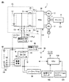
図1は、本実施の形態に係るハイブリッド車両1(以下、車両1と記載する)の構成の一部を概略的に示す図である。図1に示すように、本実施の形態に係る車両1は、電池パック20と、PCU(Power Control Unit)30と、ソーラーPCU40と、ソーラーパネル50と、ソーラーバッテリー60と、補機バッテリ70とを備える。
FIG. 1 is a diagram schematically showing a part of the configuration of a hybrid vehicle 1 (hereinafter referred to as a vehicle 1) according to the present embodiment. As shown in FIG. 1, the
電池パック20は、再充電可能な直流電源である。電池パック20は、たとえば、ニッケル水素電池やリチウムイオン電池等の二次電池を含む。電池パック20は、後述する2基のモータジェネレータ(図2参照)のうちの少なくともいずれか(以下、単にモータジェネレータと記載する)との間で電力を授受する。電池パック20の電力は、PCU30を経由してモータジェネレータに供給される。また、電池パック20は、モータジェネレータにより発電された電力を用いて充電される。なお、電池パック20は、車両1の外部の電源(図示せず)から供給される電力を用いて充電されてもよい。なお、電池パック20は、二次電池に限らず、モータジェネレータとの間で直流電力を授受できるもの、たとえば、キャパシタ等であってもよい。電池パック20は、たとえば、車両1の後部座席よりも下方の位置であって、かつ、左右の後輪のホイールハウス間に設けられる。
The
PCU30は、電池パック20の直流電力を交流電力に変換してモータジェネレータに供給したり、モータジェネレータにおいて生じた回生電力(交流電力)を直流電力に変換して電池パック20に供給したりする。
The
PCU30は、たとえば、複数個のスイッチング素子を有する、コンバータおよびインバータ(いずれも図示せず)を含む。コンバータやインバータは、スイッチング素子のオン・オフ制御によって動作する。コンバータは、電池パック20から受けた直流電力の電圧を昇圧してインバータに出力する。インバータは、コンバータが出力した直流電力を交流電力に変換してモータジェネレータに出力する。これにより、電池パック20に蓄えられた電力を用いてモータジェネレータが駆動される。
また、インバータは、モータジェネレータによって発電される交流電力を直流電力に変換してコンバータに出力する。コンバータは、インバータが出力した直流電力の電圧を降圧して電池パック20へ出力する。これにより、モータジェネレータにより発電された電力を用いて電池パック20が充電される。なお、コンバータは、省略してもよい。
The inverter converts AC power generated by the motor generator into DC power and outputs the DC power to the converter. The converter steps down the voltage of the DC power output from the inverter and outputs it to the
PCU30は、電池パック20の電圧を補機バッテリ70の充電に適した電圧に変換するDC/DCコンバータ(図示せず)をさらに含む。DC/DCコンバータは、変換された電力を補機バッテリ70に供給することによって補機バッテリ70を充電する。
ソーラーパネル50は、光エネルギー(たとえば、太陽光の光エネルギー)を直流電力に変換する太陽電池である。本実施の形態において、ソーラーパネル50は、図1に示すように車両1の屋根の表面に設置される。ソーラーパネル50において発電された電力は、ソーラーPCU40を経由してソーラーバッテリー60に供給される。なお、ソーラーパネル50は、車両1の屋根以外の箇所(たとえば、ボンネット等)の表面に配置されてもよい。
The
ソーラーバッテリー60は、ソーラーパネル50において発電された電力を蓄電する蓄電装置である。ソーラーバッテリー60は、複数個(たとえば、3個)のセルまたは複数個のセルにより構成されたモジュールが直列に接続されて構成される。ソーラーバッテリー60は、車両1の室内の所定位置(たとえば、センターコンソールの下部)に設けられる。なお、車両1の室内とは、乗員が搭乗する車両1内の空間(たとえば、キャビン)および当該空間に連通する空間(たとえば、荷室等)を含むものとする。
The
ソーラーPCU40は、ECU(Electronic Control Unit)100(図2参照)からの制御信号に応じて、ソーラーパネル50から出力された直流電力をソーラーバッテリー60の充電が可能な電圧に変換したり、ソーラーバッテリー60の直流電力を電池パック20の充電が可能な電圧に変換したりする。具体的には、ソーラーPCU40は、たとえば、ソーラーバッテリー60のSOCが上限値に達するまで増加した場合に、ソーラーバッテリー60の電力を用いて電池パック20を充電したり、あるいは、補機バッテリ70を充電したりする。あるいは、ソーラーPCU40は、たとえば、ソーラーバッテリー60のSOCが下限値に達するまで減少した場合に、ソーラーパネル50から出力された電力を用いてソーラーバッテリー60を充電する。
The
補機バッテリ70は、補機負荷に対して電力を供給する。補機負荷は、たとえば、車両1の室内に設けられる電気機器(たとえば、ナビゲーションシステム104(図2参照)やオーディオ機器(図示せず)等)や、車両1に搭載される各種ECU等を含む。
The
以下に、図2を用いて車両1に搭載される各構成について詳細に説明する。図2は、本実施の形態に係る車両1に搭載された機器の構成を示すブロック図である。図2に示すように、車両1は、駆動輪2と、エンジン4と、動力分割装置6と、第1モータジェネレータ10(以下、第1MG10と記載する)と、第2モータジェネレータ12(以下、第2MG12と記載する)と、ECU100と、回復モードスイッチ102と、ナビゲーションシステム104とをさらに備える。
Hereinafter, each configuration mounted on the
車両1は、エンジン4および第2MG12のうちの少なくとも一方の動力を用いて走行する。車両1は、エンジン4の動力を用いずに第2MG12の動力を用いる電気自動車走行(EV走行)と、エンジン4および第2MG12の両方の動力を用いるハイブリッド自動車走行(HV走行)との間で車両1の走行態様を切り替えることができる。
エンジン4は、ガソリンエンジンまたはディーゼルエンジン等の内燃機関である。エンジン4は、ECU100からの制御信号に応じて車両1が走行するための動力を発生する。エンジン4において発生した動力は動力分割装置6に出力される。
The engine 4 is an internal combustion engine such as a gasoline engine or a diesel engine. The engine 4 generates power for the
エンジン4の出力軸、第1MG10の回転軸および第2MG12の回転軸は、動力分割装置6の各回転要素にそれぞれ機械的に連結される。
The output shaft of engine 4, the rotation shaft of
動力分割装置6は、エンジン4の出力軸、第1MG10の回転軸および第2MG12の回転軸に機械的に連結し、エンジン4、第1MG10および第2MG12の間でトルクを伝達可能に構成されている。具体的には、動力分割装置6は、遊星歯車機構である。遊星歯車機構は、回転要素としてサンギヤと、リングギヤと、キャリアと、ピニオンギヤとを含む。外歯歯車のサンギヤを中心とし、複数のピニオンギヤの各々がサンギヤと噛み合うように設けられ、内歯歯車のリングギヤが複数のピニオンギヤの各々と噛み合うように設けられる。複数のピニオンギヤは、キャリアによって自転可能かつ公転可能なように保持される。サンギヤは、第1MG10の回転軸に機械的に連結される。キャリアは、エンジン4の出力軸に機械的に連結される。リングギヤは、第2MG12の回転軸に機械的に連結される。第2MG12の回転軸には、減速機やデファレンシャルギヤ等(図示せず)を介して駆動輪2が連結される。
Power split
第1MG10、第2MG12の各々は、たとえば、3相交流永久磁石型同期モータ等によって構成される回転電機である。第1MG10は、エンジン4を始動させる際には組電池22の電力を用いてエンジン4の出力軸を回転させるように制御される。また、第1MG10は、エンジン4の動力を用いて発電するように制御することも可能である。第1MG10によって発電された交流電力は、PCU30により直流電力に変換されて組電池22に充電される。また、第1MG10によって発電された交流電力が第2MG12に供給される場合もある。
Each of
第2MG12は、組電池22からの供給電力および第1MG10による発電電力の少なくとも一方を用いて駆動輪2を回転させる。また、第2MG12は、回生制動によって発電することも可能である。第2MG12によって発電された交流電力は、PCU30により直流電力に変換される。変換された直流電力は、組電池22の充電に用いられる。
電池パック20は、組電池22と、システムメインリレー(以下、SMRと記載する)24と、充電リレー(以下、CHRと記載する)26とを含む。
The
組電池22は、複数個のセルにより構成されたモジュールが複数個直列に接続されて構成される。あるいは、組電池22は、複数個のセルが直列に接続されて構成されてもよい。組電池は、組電池22の電圧は、たとえば、200V程度である。
The assembled
SMR24は、PCU30と組電池22とを接続する電力線PL1,NL1上に設けられる。SMR24は、ECU100からの制御信号C1に基づいて、PCU30と組電池22との間を電気的に接続状態(オン状態)にしたり、遮断状態(オフ状態)にしたりする。
The
CHR26は、組電池22とSMR24とを接続する電力線PL1,NL1から分岐してソーラーPCU40に接続される電力線PL2,NL2上に設けられる。CHR26は、ECU100からの制御信号C2に基づいて、電力線PL1,NL1と、ソーラーPCU40との間を電気的に接続状態(オン状態)にしたり、遮断状態(オフ状態)にしたりする。
The
ソーラーPCU40は、高圧DC/DCコンバータ42と、ソーラーDC/DCコンバータ44と、補機DC/DCコンバータ46と、監視回路48とを含む。
高圧DC/DCコンバータ42は、ECU100からの制御信号に基づいて、ソーラーバッテリー60の直流電力を組電池22の充電が可能な直流電力に変換する。高圧DC/DCコンバータ42は、変換した電力を組電池22に供給する。
The high voltage DC /
ソーラーDC/DCコンバータ44は、ECU100からの制御信号に基づいて、ソーラーパネル50から供給される直流電力をソーラーバッテリー60の充電が可能な直流電力に変換する。ソーラーDC/DCコンバータ44は、変換した電力をソーラーバッテリー60に供給する。
The solar DC /
補機DC/DCコンバータ46は、ECU100からの制御信号に基づいて、ソーラーバッテリー60の直流電力を補機バッテリ70の充電が可能な直流電力に変換する。補機DC/DCコンバータ46は、変換した電力を補機バッテリ70に供給する。
Auxiliary machine DC /
監視回路48は、ソーラーバッテリー60の状態を監視する。ソーラーバッテリー60には、温度センサ62と、電圧センサ64と、電流センサ66とが設けられる。温度センサ62は、ソーラーバッテリー60の温度(以下、電池温度と記載する)TBsを検出し、検出された電池温度TBsを示す信号を監視回路48に送信する。電圧センサ64は、ソーラーバッテリー60全体の電圧VBsを検出し、検出された電圧VBsを示す信号を監視回路48に送信する。電流センサ66は、ソーラーバッテリー60の電流IBsを検出し、検出された電流IBsを示す信号を監視回路48に送信する。
The
監視回路48は、ソーラーバッテリー60の状態についての情報をECU100に出力する。監視回路48は、たとえば、各センサから受信した検出結果をECU100に出力したり、あるいは、各センサから受信した検出結果に対して所定の演算処理を実行し、実行結果をECU100に出力したりする。具体的には、監視回路48は、ソーラーバッテリー60の温度TBs、電圧VBsおよび電流IBsに基づいてソーラーバッテリー60のSOCを算出し、算出されたSOCを示す情報をECU100に出力する。
The
監視回路48は、たとえば、ソーラーバッテリー60の電流IBsと、電圧VBsと、電池温度TBsとに基づいてOCV(Open Circuit Voltage)を推定し、推定されたOCVと所定のマップとに基づいてソーラーバッテリー60のSOCを推定してもよい。あるいは、監視回路48は、たとえば、ソーラーバッテリー60の充電電流と放電電流とを積算することによってソーラーバッテリー60のSOCを推定してもよい。
The
ECU100は、いずれも図示しないが、CPU(Central Processing Unit)、記憶装置であるメモリ、および、入出力バッファ等を含んで構成される。ECU100は、各センサおよび機器からの信号、ならびにメモリに格納されたマップおよびプログラムに基づいて、車両1が所望の作動状態となるように各種機器を制御する。なお、各種制御については、ソフトウェアによる処理に限られず、専用のハードウェア(電子回路)により処理することも可能である。
Although not shown, the
ECU100は、監視回路48からソーラーバッテリー60のSOCを取得する。なお、上述した監視回路48で実行されたSOCを算出する処理は、ECU100で実行されてもよい。ECU100は、ソーラーバッテリー60のSOCが下限値に達すると、ソーラーDC/DCコンバータ44を動作させてソーラーパネル50から出力される電力を用いてソーラーバッテリー60を充電する。
The
ECU100は、ソーラーバッテリー60のSOCが上限値に達すると、ソーラーバッテリー60の充電を停止するとともにCHR26をオン状態にする。ECU100は、高圧DC/DCコンバータ42を動作させてソーラーバッテリー60の電力を用いて組電池22を充電する。なお、ECU100は、高圧DC/DCコンバータ42に加えてソーラーDC/DCコンバータ44を動作させて組電池22を充電してもよい。ECU100は、ソーラーバッテリー60のSOCが下限値に達したり、あるいは、組電池22のSOCが上限値に達したりする場合に、高圧DC/DCコンバータ42の動作を停止するとともにCHR26をオフ状態にして、組電池22の充電を停止する。
When the SOC of the
ECU100は、上述のようにCHR26およびソーラーPCU40を動作させることによってソーラーバッテリー60のSOCが上限値と下限値との間の範囲内に収まるようにソーラーバッテリー60の充放電を制御する。以下の説明においてこのような制御を電力供給制御と記載する場合がある。
ECU100には、回復モードスイッチ102と、ナビゲーションシステム104とが接続される。回復モードスイッチ102は、ユーザが車両1の制御モードとして回復モードの選択を要求する場合に操作される操作部材である。回復モードスイッチ102は、ユーザによる操作を受け付けると、回復モードスイッチ102が操作されたことを示す信号をECU100に送信する。ECU100は、回復モードの非選択時に当該信号を受信する場合に、ユーザにより回復モードスイッチ102に対してオン操作されたと判定する。ECU100は、オン操作されたと判定する場合に、回復モードの選択中であるか否かを示すフラグをオン状態にする。また、ECU100は、回復モードの選択中に当該信号を受信する場合に、ユーザにより回復モードスイッチ102に対してオフ操作されたと判定する。ECU100は、オフ操作されたと判定する場合に、当該フラグをオフ状態にする。
A
回復モードは、エンジン4が停止状態である場合には、エンジン4を始動させて、エンジン4の動力を用いて第1MG10において発電し、発電された電力によって組電池22のSOCをしきい値以上になるまで上昇させる制御モードを含む。なお、しきい値は、組電池22のSOCの上限値であってもよいし、現在のSOCを所定量だけ増加した値であってもよい。ECU100は、回復モード中に、組電池22のSOCがしきい値以上となる場合には、エンジン4を停止させてもよいし、作動状態を継続してもよい。なお、回復モードは、所定時間が経過するまで第1MG10において一定の発電電力で発電することによってSOCを上昇させる制御モードであってもよい。
In the recovery mode, when the engine 4 is in a stopped state, the engine 4 is started, the
ナビゲーションシステム104は、ユーザの要求に応じて、ユーザによって設定された目的地までの移動経路を決定する。また、ナビゲーションシステム104は、車両1の運転時に、決定された移動経路あるいはユーザによって設定された移動経路に沿って車両1が進行するように車両1の室内に設けられた表示装置(図示せず)において現在位置に対応した案内表示(右折、直進あるいは左折等)を行なう。ナビゲーションシステム104は、内蔵されたGPS(Global Positioning System)によって車両1の現在位置(たとえば、緯度および経度によって特定される現在位置)を検出する。ナビゲーションシステム104は、たとえば、車両1の現在位置と地図情報(緯度および経度に応じた標高の情報を含む)とから現在位置の標高を取得する。また、ナビゲーションシステム104は、たとえば、設定された目的地と地図情報とから目的地に関する情報(目的地の緯度、経度および標高等)を取得する。ナビゲーションシステム104は、現在位置に関する情報(現在位置の緯度、経度および標高等)と、目的地に関する情報とをECU100に送信する。
The
このような構成を有する車両1において、組電池22を充電するためのエネルギーとして、ソーラーバッテリー60に蓄えられたエネルギーの他に、エンジン4と第1MG10とを用いた発電エネルギーや第2MG12における回生制動による回生エネルギー等を利用することができる。そのため、発電エネルギーや回生エネルギー等を用いた組電池22の充電を行なう場合にも、ソーラーバッテリー60を用いた組電池22の充電を継続すると、ソーラーバッテリー60がソーラーパネル50を用いて充電され、不必要に高温かつ高SOC状態になる場合がある。その結果、ソーラーバッテリー60の劣化が促進される可能性がある。
In the
そこで、本実施の形態においては、ECU100は、モータジェネレータ(第1MG10または第2MG12)によって発電された発電電力を用いて組電池22を充電する充電制御の実行中においては、ソーラーバッテリー60の充放電の禁止、および、ソーラーバッテリー60のSOCの上限値の低下のうちのいずれかを実行するものとする。
Therefore, in the present embodiment,
このようにすると、当該充電制御の実行中に、ソーラーバッテリー60が、劣化が促進される高SOC状態になることを抑制することができる。そのため、ソーラーバッテリー60の劣化を抑制することができる。
If it does in this way, it can suppress that the
本実施の形態においては、モータジェネレータによって発電された発電電力を用いて組電池22を充電する充電制御として回復モードが選択中である場合の組電池22の充電制御(すなわち、第1MG10によって発電された発電電力を用いて組電池22を充電する充電制御)を一例として説明する。
In the present embodiment, the charging control of the assembled
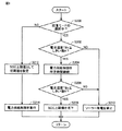
以下、図3を用いてECU100で実行される制御処理について説明する。図3は、本実施の形態に係る車両1に搭載されたECU100で実行される制御処理を示すフローチャートである。
Hereinafter, a control process executed by the
ステップ(以下、ステップを「S」と記載する)100にて、ECU100は、回復モードの選択中であるか否かを判定する。ECU100は、たとえば、上述した回復モードの選択中であるか否かを示すフラグがオン状態である場合に回復モードの選択中であると判定し、当該フラグがオフ状態である場合に回復モードの選択中でないと判定する。回復モードが選択中であると判定される場合(S100にてYES)、処理はS102に移される。
In step (hereinafter, step is referred to as “S”) 100,
S102にて、ECU100は、電池温度TBsがしきい値A以下であるか否かを判定する。しきい値Aは、たとえば、ソーラーバッテリー60の温度環境が、劣化が促進される高温環境であるか否かを判定するためのしきい値である。電池温度TBsがしきい値A以下であると判定される場合(S102にてYES)、処理はS106に移される。
In S102,
S104にて、ECU100は、ソーラーバッテリー60のSOCの上限値を初期値SOC_u(0)よりも低い値SOC_u(1)に設定する。SOC_u(1)としては、たとえば、電池温度TBsがしきい値A以下の温度環境下でソーラーバッテリー60のSOCが上限値になるまで充電されても劣化が促進されるような高SOC状態にならない程度の値が設定される。
In S104,
S106にて、ECU100は、ソーラーバッテリー60のSOCが上限値になると電池パック20に電力を供給し、下限値になるとソーラーパネル50を用いて充電する、上述した電力供給制御を実行する。
In S106,
なお、電池温度TBsがしきい値Aよりも高い場合には(S102にてNO)、処理はS108に移される。S108にて、ECU100は、ソーラーパネル50を用いた発電(以下、ソーラー発電とも記載する)を禁止する。具体的には、ECU100は、ソーラーDC/DCコンバータ44の作動を停止して、ソーラー発電を禁止することによって、ソーラーバッテリー60の充電を禁止する。
If battery temperature TBs is higher than threshold value A (NO in S102), the process proceeds to S108. In S108,
また、回復モードの選択中でないと判定される場合(S100にてNO)、処理はS110に移される。S110にて、ECU100は、ソーラーバッテリー60のSOCの上限値を初期値SOC_u(0)に設定し、処理をS106に移す。
If it is determined that the recovery mode is not being selected (NO in S100), the process proceeds to S110. In S110,
以上のような構造およびフローチャートに基づく本実施の形態に係る車両1の動作について図4を参照しつつ説明する。図4は、本実施の形態に係る車両1に搭載されたECU100の動作を説明するためのタイミングチャートである。図4の横軸は、時間を示し、図4の縦軸は、回復モードの選択状態と、エンジン4の作動状態と、SOCの上限値と、ソーラー発電の実行状態と、電池温度TBsとを示す。すなわち、図4のLN1は、回復モードの選択状態の変化を示す。図4のLN2は、エンジン4の作動状態の変化を示す。図4のLN3は、ソーラーバッテリー60のSOCの上限値の変化を示す。図4のLN4は、ソーラー発電の実行状態の変化を示す。図4のLN5は、電池温度TBsの変化を示す。
An operation of the
たとえば、回復モードが選択されておらず、エンジン4を停止させた状態でEV走行を実施している場合を想定する。また、電池温度TBsは、しきい値Aよりも低いものとする。 For example, it is assumed that the recovery mode is not selected and the EV traveling is performed with the engine 4 stopped. Further, the battery temperature TBs is assumed to be lower than the threshold value A.
この場合、図4のLN1に示すように、回復モードが選択されていないため(S100にてNO)、図4のLN3に示すように、ソーラーバッテリー60のSOCの上限値として初期値SOC_u(0)が設定され(S110)、電力供給制御が実行される(S106)。そのため、図4のLN4に示すようにソーラー発電が継続して行なわれる。
In this case, since the recovery mode is not selected as indicated by LN1 in FIG. 4 (NO in S100), initial value SOC_u (0) is set as the upper limit value of the SOC of
時間T(0)にて、ユーザにより回復モードスイッチ102に対してオン操作が行なわれると、図4のLN1に示すように、回復モードが選択される(S100にてYES)。回復モードが選択されることによって、図4のLN2に示すように、エンジン4が作動状態になる。このとき、図4のLN5に示すように、電池温度TBsがしきい値Aよりも低いため(S102にてYES)、図4のLN3に示すように、ソーラーバッテリー60のSOCの上限値が初期値SOC_u(0)からSOC_u(1)に低下されるとともに(S104)、電力供給制御が実行される(S106)。電池温度TBsがしきい値Aよりも低いため、図4のLN4に示すように、ソーラー発電が継続して行なわれる。
When the user turns on
時間T(1)にて、図4のLN5に示すように、電池温度TBsがしきい値Aを超えると(S102にてNO)、図4のLN4に示すように、ソーラー発電が禁止される(S108)。そのため、ソーラーバッテリー60における充電が抑制される。
At time T (1), when battery temperature TBs exceeds threshold value A (NO in S102) as indicated by LN5 in FIG. 4, solar power generation is prohibited as indicated by LN4 in FIG. (S108). Therefore, charging in the
時間T(2)にて、ユーザの操作によって回復モードスイッチ102に対してオフ操作が行なわれると、図4のLN1に示すように、回復モードが非選択状態になる(S100にてNO)。回復モードが選択されていないため(S100にてNO)、図4のLN2に示すように、エンジン4が停止状態になる。さらに、ソーラーバッテリー60のSOCの上限値が初期値SOC_u(0)に戻されて(S110)、電力供給制御が実行される(S106)。そのため、図4のLN4に示すように、ソーラー発電が再開される。
If the
以上のようにして、本実施の形態に係る車両1によると、ユーザの要求に応じて回復モードが選択される場合には、ソーラーバッテリー60の充電が禁止されたり、あるいは、ソーラーバッテリー60のSOCの上限値が低下されたりする。そのため、回復モードの選択中に、ソーラーバッテリー60が高SOC状態になることを抑制することができる。そのため、ソーラーバッテリー60の劣化を抑制することができる。したがって、太陽電池を用いた充電が可能な第1蓄電装置と駆動力を発生させるための電源となる第2蓄電装置とを備える電動車両において第1蓄電装置の劣化を抑制する電動車両を提供することができる。
As described above, according to the
さらに、回復モードの選択中において、電池温度TBsがしきい値Aよりも高いと、ソーラーバッテリー60の充電が禁止されるため、ソーラーバッテリー60が高温かつ高SOC状態になることを抑制することができる。そのため、ソーラーバッテリー60の劣化を抑制することができる。
Furthermore, if the battery temperature TBs is higher than the threshold value A during the selection of the recovery mode, charging of the
さらに、回復モードの選択中において、電池温度TBsがしきい値A以下であると、ソーラーバッテリー60のSOCの上限値が低下させられるため、ソーラーバッテリー60が高SOC状態になることを抑制することができる。そのため、ソーラーバッテリー60の劣化を抑制することができる。
Further, when the recovery mode is selected, if the battery temperature TBs is equal to or lower than the threshold value A, the upper limit value of the SOC of the
以下、変形例について記載する。
上述の実施の形態では、回復モードの選択中においては、温度センサ62を用いて検出された電池温度TBsに応じてソーラーバッテリー60のSOCの上限値を低下させるかソーラーバッテリー60の充電を禁止するかを決定するものとして説明したが、たとえば、車両1の室内の温度に基づいて電池温度TBsを推定し、推定された電池温度TBsに応じてSOCの上限値を低下させるかソーラーバッテリー60の充電を禁止するかを決定してもよい。あるいは、ソーラーバッテリー60の周辺の温度(雰囲気温度)に基づいて電池温度TBsを推定し、推定された電池温度TBsに応じてSOCの上限値を低下させるかソーラーバッテリー60の充電を禁止するかを決定してもよい。あるいは、外気温に基づいて電池温度TBsを推定し、推定された電池温度TBsに応じてSOCの上限値を低下させるかソーラーバッテリー60の充電を禁止するかを決定してもよい。
Hereinafter, modifications will be described.
In the above-described embodiment, during the selection of the recovery mode, the upper limit value of the SOC of the
さらに上述の実施の形態では、温度センサ62は、ソーラーバッテリー60に1箇所設けられる場合を一例として説明したが、温度センサ62は、ソーラーバッテリー60に複数個設けられてもよい。温度センサ62は、たとえば、ソーラーバッテリー60の各セルに設けられるものであってもよいし、あるいは、ソーラーバッテリー60において所定セルあるいは所定距離の間隔で設けられるものであってもよい。この場合、ECU100は、複数の温度センサの検出結果のうちの最も高い値を電池温度TBsとして検出してもよいし、あるいは、温度センサの検出結果の平均値を電池温度TBsとして検出してもよい。
Furthermore, although the case where the
さらに上述の実施の形態では、電池温度TBsがしきい値Aよりも高い場合にソーラーバッテリー60のSOCの上限値を低下させるものとして説明したが、たとえば、電池温度TBsがしきい値Aよりも高い場合にソーラーバッテリー60のSOCの上限値に加えて下限値を低下させるようにしてもよい。このようにすると、ソーラーバッテリー60の劣化を抑制しつつ、ソーラーバッテリー60における蓄電量を維持することができる。
Further, in the above-described embodiment, it has been described that the upper limit value of the SOC of the
さらに上述の実施の形態では、回復モードの選択中であると判定された時点における電池温度TBsがしきい値A以下である場合にソーラーバッテリー60のSOCの上限値を低下させ、電池温度TBsがしきい値Aよりも高い場合にソーラーバッテリー60の充電を禁止するものとして説明したが、特にこのような制御に限定されるものではない。たとえば、ECU100は、電池温度TBsがしきい値A以下である場合には、所定時間だけ電力供給制御を継続した後の電池温度TBsに基づいてソーラーバッテリー60のSOCの上限値を低下させたり、あるいは、ソーラーバッテリー60の充電を禁止したりしてもよい。
Furthermore, in the above-described embodiment, when the battery temperature TBs at the time point when it is determined that the recovery mode is being selected is equal to or lower than the threshold value A, the upper limit value of the SOC of the
以下、図5を用いてこの変形例に係る車両1に搭載されたECU100で実行される制御処理について説明する。図5は、変形例に係る車両1に搭載されたECU100で実行される制御処理を示すフローチャートである。
Hereinafter, a control process executed by the
S200にて、ECU100は、回復モードの選択中であるか否かを判定する。回復モードが選択中であると判定される場合(S200にてYES)、処理はS202に移される。
In S200,
S202にて、ECU100は、電池温度TBsがしきい値A以下であるか否かを判定する。電池温度TBsがしきい値A以下であると判定される場合(S202にてYES)、処理はS204に移される。
In S202,
S204にて、ECU100は、電力供給制御を所定時間が経過するまで実行する。ECU100は、電力供給制御を所定時間が経過するまで実行した後に処理をS206に移行する。
In S204,
S206にて、ECU100は、電池温度TBsがしきい値B以下であるか否かを判定する。しきい値Bとしては、しきい値Aと同じ値が設定されてもよいし、しきい値Aよりも低い値が設定されてもよい。電池温度TBsがしきい値B以下であると判定される場合(S206にてYES)、処理はS208に移行される。
In S206,
S208にて、ECU100は、ソーラーバッテリー60のSOCの上限値としてSOC_u(1)を設定する。S210にて、ECU100は、ソーラー発電を禁止する。S212にて、ECU100は、ソーラーバッテリー60のSOCの上限値として初期値SOC_u(0)を設定する。S214にて、ECU100は、電力供給制御を実行する。
In S208,
このようにすると、所定時間経過するまで電力供給制御が実行された後の電池温度TBsに基づいてソーラーバッテリー60のSOCの上限値を低下させる動作や、ソーラーバッテリー60の充電を禁止する動作を選択することができる。そのため、電池温度TBsの経時変化に応じて適切な動作を選択することができる。その結果、ソーラーバッテリー60の劣化を抑制することができる。
In this way, an operation for reducing the upper limit value of the SOC of the
さらに上述の実施の形態では、回復モードの選択中であると、電池温度TBsがしきい値A以下である場合にソーラーバッテリー60のSOCの上限値を低下させ、電池温度TBsがしきい値Aよりも高い場合にソーラー発電を禁止するものとして説明したが、たとえば、回復モードの選択中であると、電池温度TBsに関わらずSOCの上限値を低下させてもよい。この変形例において、ECU100は、たとえば、図6のフローチャートに示す処理を実行する。図6に示すフローチャートは、図3のフローチャートと比較して、回復モードの選択中である場合に(S100にてYES)、処理をS104に移すものとし、S102の処理とS108の処理を省略した点が異なり、その他の処理は同様である。そのため、その詳細な説明は繰り返さない。
Further, in the above-described embodiment, when the recovery mode is being selected, when the battery temperature TBs is equal to or lower than the threshold value A, the upper limit value of the SOC of the
あるいは、回復モードの選択中であると、電池温度TBsに関わらずソーラー発電を禁止してもよい。この変形例において、ECU100は、たとえば、図7のフローチャートに示す処理を実行する。図7に示すフローチャートは、図3のフローチャートと比較して、回復モードの選択中である場合に(S100にてYES)、処理をS108に移すものとし、S102の処理とS104の処理を省略した点が異なり、その他の処理は同様である。そのため、その詳細な説明は繰り返さない。
Alternatively, when the recovery mode is being selected, solar power generation may be prohibited regardless of the battery temperature TBs. In this modification, the
さらに上述の実施の形態では、モータジェネレータによって発電された発電電力を用いて組電池22を充電する充電制御として、回復モードが選択中である場合の組電池22の充電制御(すなわち、第1MG10によって発電された発電電力を用いて組電池22を充電する充電制御)を一例として説明したが、特にこのような充電制御に限定されるものではない。たとえば、モータジェネレータによって発電された発電電力を用いて組電池22を充電する充電制御は、第2MG12を用いた回生制動によって組電池22を充電する充電制御であってもよい。
Further, in the above-described embodiment, as the charging control for charging the assembled
すなわち、ECU100は、第2MG12を用いた回生制動によって組電池22を充電する充電制御の実行中に、ソーラーバッテリー60のSOCの上限値の低下、および、ソーラーバッテリー60の充電の禁止のうちのいずれかを行なってもよい。
That is, the
以下の説明においては、組電池22のSOCが現在値から上限値になるまでに要する電力量から、車両1が現在位置から目的地までの移動中に生じる第2MG12の回生エネルギーによって増加する組電池22のSOCの増加量に相当する電力量の推定値を減算した差分値が、移動中にソーラーパネル50を用いて発電される発電電力量の推定値よりも小さい場合に、ソーラーバッテリー60の充電の禁止を行なう場合を一例として説明する。
In the following description, the assembled battery is increased by the regenerative energy of the
このようにすると、目的地までの移動中において、ソーラーバッテリー60の充電が禁止されることになるため、回生制動によって組電池22を充電する充電制御の実行中においても、ソーラーバッテリー60の充電が禁止されることになる。そのため、ソーラーバッテリー60が高SOC状態になることを抑制することができる。
In this way, charging of the
以下、図8を用いてこの変形例に係る車両に搭載されたECU100で実行される制御処理について説明する。図8は、変形例に係る車両に搭載されたECU100で実行される制御処理を示すフローチャートである。なお、ECU100は、図8のフローチャートに示される処理を繰り返し実行してもよいし、あるいは、目的地が変更される毎に実行してもよい。
Hereinafter, the control process executed by the
S300にて、ECU100は、現在位置と目的地との情報から現在位置から目的地までの水平方向についての直線距離と標高差とを算出し、算出された直線距離と標高差とから平均勾配と経路長さの概算値とを算出する。ECU100は、たとえば、ナビゲーションシステム104から車両1の現在位置に関する情報と目的地に関する情報とを取得する。
In S300,
S302は、ECU100は、回生量の推定値を算出する。この回生量は、車両1が現在位置から目的地までの移動中に生じる第2MG12の回生エネルギーによって増加するSOCの増加量に相当する電力量を示す。ECU100は、たとえば、算出された平均勾配と経路長さの概算値とから目的地までの回生量の推定値を算出する。ECU100は、たとえば、平均勾配と経路長さと回生量の推定値との関係を示すマップや関数等を用いて算出された平均勾配と経路長さとから目的地までの回生量の推定値を算出する。
In S302, the
S304にて、ECU100は、ソーラー発電量の推定値を算出する。具体的には、ECU100は、経路長さと目的地までの制限速度等の情報に基づく平均速度の推定値とから移動期間を算出し、現在のソーラーパネル50の発電電力(あるいは今後の平均発電電力の推定値)と、算出された移動期間とからソーラー発電量の推定値を算出する。
In S304,
S306にて、ECU100は、ソーラー発電量の推定値が、組電池22のSOCが上限値になるまでに要する電力量から回生量の推定値を減算した差分値以上であるか否かを判定する。ソーラー発電量が差分値以上であると判定される場合(S306にてYES)、処理はS308に移される。S308にて、ECU100は、ソーラー発電を禁止する。
In S306,
このようにすると、目的地までの移動中における差分値が、ソーラーパネル50を用いて発電される発電電力量の推定値よりも小さい場合には、移動中におけるソーラーパネル50を用いて発電される発電電力量を組電池22において全て受け入れることができない。そのため、ソーラーバッテリー60の充電を禁止することにより、ソーラーバッテリー60が不必要に充電されることを抑制することができる。これにより、ソーラーバッテリー60の劣化を抑制することができる。
In this way, when the difference value during the movement to the destination is smaller than the estimated value of the generated electric power generated using the
なお、本変形例においては、差分値がソーラーパネル50を用いて発電される発電電力量の推定値よりも小さい場合には、ソーラー発電を禁止するものとして説明したが、ソーラー発電を禁止することに代えてソーラーバッテリー60のSOCの上限値を低下させてもよい。たとえば、ソーラーパネル50を用いて発電される発電電力量の推定値が差分値以下になるようにソーラーバッテリー60のSOCの上限値を低下させてもよいし、予め定められた値だけソーラーバッテリー60のSOCの上限値を低下させてもよい。この変形例において、ECU100は、たとえば、図9のフローチャートに示す処理を実行する。図9に示すフローチャートは、図8に示すフローチャートと比較して、S308の処理をソーラーバッテリー60のSOCの上限値を低下させる処理(S408)と、電力供給制御を実行する処理(S410)とに置き換えている点で異なり、その他の処理については同様である。また、S408およびS410の処理は、図3のフローチャートのS104およびS106の処理と同様であるため、その詳細な説明は繰り返さない。
In addition, in this modification, when the difference value was smaller than the estimated value of the generated electric power generated using the
あるいは、ECU100は、差分値がソーラーパネル50を用いて発電される発電電力量の推定値よりも小さい場合には、ソーラーバッテリー60の温度がしきい値Aよりも高いと、ソーラー発電を禁止し、ソーラーバッテリー60の温度がしきい値A以下であると、ソーラーバッテリー60のSOCの上限値を低下させてもよい。この変形例において、ECU100は、たとえば、図10のフローチャートに示す処理を実行する。図10に示すフローチャートは、図8に示すフローチャートと比較して、S308の処理をS502、S504、S506およびS508の処理に置き換えている点で異なり、その他の処理については同様である。また、S502、S504、S506およびS508の処理は、図3のS102、S104、S106およびS108の処理とそれぞれ同様であるため、その詳細な説明は繰り返さない。
Alternatively, the
なお、上記した変形例は、その全部または一部を適宜組み合わせて実施してもよい。
今回開示された実施の形態はすべての点で例示であって制限的なものではないと考えられるべきである。本開示の範囲は上記した説明ではなくて特許請求の範囲によって示され、特許請求の範囲と均等の意味および範囲内でのすべての変更が含まれることが意図される。
In addition, you may implement the above-mentioned modification combining all or one part suitably.
The embodiment disclosed this time should be considered as illustrative in all points and not restrictive. The scope of the present disclosure is defined by the terms of the claims, rather than the description above, and is intended to include any modifications within the scope and meaning equivalent to the terms of the claims.
1 車両、2 駆動輪、4 エンジン、6 動力分割装置、10,12 MG、20 電池パック、22 組電池、24 SMR、26 CHR、30 PCU、40 ソーラーPCU、42 高圧DC/DCコンバータ、44 ソーラーDC/DCコンバータ、46 補機DC/DCコンバータ、48 監視回路、50 ソーラーパネル、60 ソーラーバッテリー、62 温度センサ、64 電圧センサ、66 電流センサ、70 補機バッテリ、100 ECU、102 回復モードスイッチ、104 ナビゲーションシステム。 1 vehicle, 2 drive wheels, 4 engine, 6 power split device, 10, 12 MG, 20 battery pack, 22 battery pack, 24 SMR, 26 CHR, 30 PCU, 40 solar PCU, 42 high voltage DC / DC converter, 44 solar DC / DC converter, 46 auxiliary DC / DC converter, 48 monitoring circuit, 50 solar panel, 60 solar battery, 62 temperature sensor, 64 voltage sensor, 66 current sensor, 70 auxiliary battery, 100 ECU, 102 recovery mode switch, 104 Navigation system.
Claims (6)
光のエネルギーを電力に変換する太陽電池と、
前記太陽電池から出力される電力を用いて充電される第1蓄電装置と、
前記回転電機において発電された電力を用いた充電が可能であって、かつ、車両の駆動力を発生させるための電源である第2蓄電装置と、
前記第1蓄電装置の電力を用いて前記第2蓄電装置を充電する第1充電制御と、前記回転電機において発電された発電電力を用いて前記第2蓄電装置を充電する第2充電制御とを実行可能な制御装置とを備え、
前記制御装置は、前記第2充電制御の実行中においては、前記第1蓄電装置の充電の禁止、および、前記第1蓄電装置のSOCの上限値の低下のうちのいずれかを実行する、電動車両。 Rotating electrical machinery,
A solar cell that converts light energy into electric power;
A first power storage device that is charged using electric power output from the solar cell;
A second power storage device that is capable of charging using electric power generated in the rotating electrical machine and that is a power source for generating a driving force of the vehicle;
A first charging control for charging said second power storage device using the power of the first power storage device, and a second charging control for charging said second power storage device by using the generated power generated in the rotary electric machine An executable control device,
The control device performs one of prohibiting charging of the first power storage device and decreasing the upper limit value of the SOC of the first power storage device during execution of the second charge control. vehicle.
前記制御装置は、前記第2充電制御の実行時において前記エンジンの動力を用いて前記回転電機において発電させる、請求項1〜3のいずれかに記載の電動車両。 The electric vehicle further includes an engine coupled to the rotating electrical machine,
The electric vehicle according to any one of claims 1 to 3, wherein the control device causes the rotating electric machine to generate electric power using the power of the engine when the second charging control is executed.
前記制御装置は、前記第2蓄電装置のSOCが現在値から上限値になるまでに要する電力量から、前記電動車両が現在位置から目的地までの移動中に生じる前記回転電機の回生エネルギーによって増加するSOCの増加量に相当する電力量の推定値を減算した差分値が、前記移動中に前記太陽電池を用いて発電される発電電力量の推定値よりも小さい場合に、前記第1蓄電装置の充電の禁止、および、前記第1蓄電装置のSOCの上限値の低下のうちのいずれかを実行する、請求項1〜3のいずれかに記載の電動車両。 The rotating electrical machine is connected to drive wheels,
The control device increases the amount of electric power required for the SOC of the second power storage device from the current value to the upper limit value by the regenerative energy of the rotating electrical machine generated while the electric vehicle is moving from the current position to the destination. The first power storage device when a difference value obtained by subtracting an estimated value of the amount of power corresponding to an increase amount of SOC to be performed is smaller than an estimated value of the generated power amount generated using the solar battery during the movement The electric vehicle according to any one of claims 1 to 3, wherein any one of prohibition of charging and lowering of an upper limit value of SOC of the first power storage device is executed.
Priority Applications (3)
| Application Number | Priority Date | Filing Date | Title |
|---|---|---|---|
| JP2017005985A JP6583294B2 (en) | 2017-01-17 | 2017-01-17 | Electric vehicle |
| US15/861,162 US10351011B2 (en) | 2017-01-17 | 2018-01-03 | Electric vehicle |
| CN201810020969.3A CN108327543B (en) | 2017-01-17 | 2018-01-10 | Electric vehicle |
Applications Claiming Priority (1)
| Application Number | Priority Date | Filing Date | Title |
|---|---|---|---|
| JP2017005985A JP6583294B2 (en) | 2017-01-17 | 2017-01-17 | Electric vehicle |
Publications (2)
| Publication Number | Publication Date |
|---|---|
| JP2018117436A JP2018117436A (en) | 2018-07-26 |
| JP6583294B2 true JP6583294B2 (en) | 2019-10-02 |
Family
ID=62838825
Family Applications (1)
| Application Number | Title | Priority Date | Filing Date |
|---|---|---|---|
| JP2017005985A Active JP6583294B2 (en) | 2017-01-17 | 2017-01-17 | Electric vehicle |
Country Status (3)
| Country | Link |
|---|---|
| US (1) | US10351011B2 (en) |
| JP (1) | JP6583294B2 (en) |
| CN (1) | CN108327543B (en) |
Families Citing this family (15)
| Publication number | Priority date | Publication date | Assignee | Title |
|---|---|---|---|---|
| JP6853805B2 (en) * | 2018-09-13 | 2021-03-31 | 株式会社Subaru | Electric vehicle |
| JP7231371B2 (en) * | 2018-10-02 | 2023-03-01 | 株式会社Subaru | VEHICLE POWER CONTROL DEVICE AND POWER CONTROL METHOD |
| KR102602811B1 (en) * | 2018-10-24 | 2023-11-20 | 현대자동차주식회사 | Vehicle and control method for the same |
| JP7006572B2 (en) * | 2018-11-27 | 2022-01-24 | トヨタ自動車株式会社 | Vehicle charge control system |
| JP7156004B2 (en) | 2018-12-25 | 2022-10-19 | トヨタ自動車株式会社 | Vehicle charging control system |
| JP2020156135A (en) | 2019-03-18 | 2020-09-24 | トヨタ自動車株式会社 | vehicle |
| KR20210033309A (en) * | 2019-09-18 | 2021-03-26 | 현대자동차주식회사 | Solar charging system and method for vehicle |
| JP2021065021A (en) * | 2019-10-11 | 2021-04-22 | トヨタ自動車株式会社 | Electric power supply control system for vehicle |
| KR20210059092A (en) * | 2019-11-14 | 2021-05-25 | 현대자동차주식회사 | Power supplier, Vehicle having the power supplier and method for controlling the vehicle |
| JP7279620B2 (en) * | 2019-11-21 | 2023-05-23 | トヨタ自動車株式会社 | solar charging system |
| JP2021090266A (en) * | 2019-12-03 | 2021-06-10 | トヨタ自動車株式会社 | Solar charging system |
| KR20210094683A (en) * | 2020-01-21 | 2021-07-30 | 현대자동차주식회사 | Control system for the solar roof of car and method therefor |
| KR20220026906A (en) * | 2020-08-26 | 2022-03-07 | 현대자동차주식회사 | Method and system for controlling high voltage power of electric vehicle |
| GB2607875A (en) * | 2021-06-09 | 2022-12-21 | Renewable Innovations And Solutions Ltd | Power system for supplying electrical energy to a refrigerator of a refrigerated vehicle and associated control system and method |
| FR3127856A1 (en) * | 2021-10-06 | 2023-04-07 | Farid Sabeur | Vehicle energy storage system |
Family Cites Families (39)
| Publication number | Priority date | Publication date | Assignee | Title |
|---|---|---|---|---|
| US5703468A (en) * | 1995-03-17 | 1997-12-30 | Petrillo; Gino A. | Electrical charge control apparatus and method for photovoltaic energy conversion systems |
| JP3416461B2 (en) * | 1997-05-30 | 2003-06-16 | キヤノン株式会社 | Solar battery charge control device |
| US6091228A (en) * | 1998-04-29 | 2000-07-18 | Lockheed Martin Corp. | Control system for, in the presence of a varying system load, establishing generator current to maintain a particular battery charge state |
| US7359769B2 (en) * | 2001-12-20 | 2008-04-15 | Rain Bird Corporation | Wireless irrigation control device and related method |
| DE10346213A1 (en) * | 2003-10-06 | 2005-04-21 | Bosch Gmbh Robert | Regulating load condition of energy storage device for vehicle with hybrid drive involves regulating state of charge of energy storage device depending on vehicle's speed of travel |
| JP4100335B2 (en) | 2003-11-28 | 2008-06-11 | 株式会社エクォス・リサーチ | Drive control device and hybrid vehicle |
| US7525286B2 (en) * | 2004-12-31 | 2009-04-28 | Jason Auto Technology Co., Ltd. | Method and device for vehicle battery protection with battery power source noise pattern analysis |
| US20120146572A1 (en) * | 2005-08-24 | 2012-06-14 | Ward Thomas A | Solar panel charging system for electric vehicle that charges individual battery cells with direct parallel connections to solar panels and interconnected charge controllers |
| US8120308B2 (en) * | 2005-08-24 | 2012-02-21 | Ward Thomas A | Solar panel charging system for electric vehicle that charges individual batteries with direct parallel connections to solar panels |
| JP2008046751A (en) * | 2006-08-11 | 2008-02-28 | Toyota Motor Corp | Photovoltaic power generation system, vehicle, control method for photovoltaic power generation system, and computer readable recording medium with program for making computer perform its control method reocrded |
| EP2201661A2 (en) * | 2007-06-25 | 2010-06-30 | David J. Muchow | Suitcase power system |
| JP2009195081A (en) * | 2008-02-18 | 2009-08-27 | Panasonic Corp | Charging control circuit, charger device equipped with circuit, and battery pack |
| JP5223920B2 (en) * | 2008-07-11 | 2013-06-26 | トヨタ自動車株式会社 | Battery charge / discharge control device and hybrid vehicle equipped with the same |
| JP4525809B2 (en) * | 2008-07-28 | 2010-08-18 | トヨタ自動車株式会社 | Power supply system, vehicle equipped with the same, and control method of power supply system |
| US9744858B2 (en) * | 2008-09-27 | 2017-08-29 | Witricity Corporation | System for wireless energy distribution in a vehicle |
| US8933594B2 (en) * | 2008-09-27 | 2015-01-13 | Witricity Corporation | Wireless energy transfer for vehicles |
| US8912687B2 (en) * | 2008-09-27 | 2014-12-16 | Witricity Corporation | Secure wireless energy transfer for vehicle applications |
| US8946938B2 (en) * | 2008-09-27 | 2015-02-03 | Witricity Corporation | Safety systems for wireless energy transfer in vehicle applications |
| CN102341285B (en) * | 2009-03-05 | 2014-07-30 | 丰田自动车株式会社 | Charging/discharging control system for hybrid vehicle and method for controlling same |
| US8253387B2 (en) * | 2009-04-24 | 2012-08-28 | GM Global Technology Operations LLC | Battery charging control methods and apparatus |
| JP2011109802A (en) | 2009-11-17 | 2011-06-02 | Sanyo Electric Co Ltd | Battery pack and charging system |
| JP2011178349A (en) * | 2010-03-03 | 2011-09-15 | Honda Access Corp | Vehicle |
| IT1402184B1 (en) * | 2010-09-16 | 2013-08-28 | Bitron Spa | PHOTOVOLTAIC PANEL CHARGER. |
| CN102570906B (en) * | 2010-12-29 | 2015-11-25 | 上海汽车集团股份有限公司 | High efficiency solar cell interface arrangement and comprise its automobile power supply system |
| JP5304844B2 (en) * | 2011-05-24 | 2013-10-02 | トヨタ自動車株式会社 | Battery charge control device |
| IN2014DN03025A (en) * | 2011-10-07 | 2015-05-08 | Toyota Motor Co Ltd | |
| JP2013143335A (en) | 2012-01-12 | 2013-07-22 | Sumitomo Electric Ind Ltd | Charging method and power supply |
| JP5966583B2 (en) * | 2012-05-11 | 2016-08-10 | 日産自動車株式会社 | Power control device |
| KR20150048875A (en) * | 2012-09-03 | 2015-05-07 | 로베르트 보쉬 (에스이에이) 프라이빗 리미티드 | Topology and control strategy for hybrid storage systems |
| JP5977658B2 (en) | 2012-12-06 | 2016-08-24 | 株式会社デンソー | Charge control device |
| US10374447B2 (en) * | 2013-03-14 | 2019-08-06 | Infineon Technologies Austria Ag | Power converter circuit including at least one battery |
| DE112013007089T5 (en) * | 2013-05-17 | 2016-01-28 | Toyota Jidosha Kabushiki Kaisha | Charge control device using a vehicle-side solar cell |
| JP6085544B2 (en) * | 2013-09-19 | 2017-02-22 | 三菱重工業株式会社 | Rapid charging equipment for electric vehicles, energy management method for charging equipment, and charging equipment system |
| US9403443B2 (en) * | 2014-01-14 | 2016-08-02 | Ford Global Technologies, Llc | Charge balance system and method |
| WO2015132625A1 (en) * | 2014-03-03 | 2015-09-11 | Robert Bosch (Sea) Pte. Ltd. | Topology and control strategy for hybrid storage systems |
| US20170070081A1 (en) * | 2014-03-06 | 2017-03-09 | Robert Bosch Gmbh | Hybrid storage system |
| JP2015199470A (en) | 2014-04-10 | 2015-11-12 | 株式会社デンソー | vehicle control system |
| CN203902312U (en) * | 2014-06-24 | 2014-10-29 | 徐州林源车业有限公司 | Wind-solar complementary self-charging electric vehicle |
| JP6939057B2 (en) * | 2017-04-27 | 2021-09-22 | トヨタ自動車株式会社 | In-vehicle battery system and battery aging estimation method |
-
2017
- 2017-01-17 JP JP2017005985A patent/JP6583294B2/en active Active
-
2018
- 2018-01-03 US US15/861,162 patent/US10351011B2/en not_active Expired - Fee Related
- 2018-01-10 CN CN201810020969.3A patent/CN108327543B/en not_active Expired - Fee Related
Also Published As
| Publication number | Publication date |
|---|---|
| US10351011B2 (en) | 2019-07-16 |
| CN108327543A (en) | 2018-07-27 |
| US20180201150A1 (en) | 2018-07-19 |
| JP2018117436A (en) | 2018-07-26 |
| CN108327543B (en) | 2021-04-23 |
Similar Documents
| Publication | Publication Date | Title |
|---|---|---|
| JP6583294B2 (en) | Electric vehicle | |
| JP6489102B2 (en) | vehicle | |
| US10155451B2 (en) | Hybrid vehicle and method of controlling the same | |
| JP6011541B2 (en) | Charge control device and charge control method | |
| EP2502775B1 (en) | Vehicle and method for controlling vehicle | |
| JP2018061372A (en) | vehicle | |
| KR101761539B1 (en) | Hybrid vehicle | |
| JP5817434B2 (en) | Vehicle and vehicle control method | |
| JP2008087516A (en) | Hybrid vehicle and drive control method of the same | |
| JP5783129B2 (en) | Electric vehicle | |
| JP2010064499A (en) | Hybrid vehicle | |
| JP2018090153A (en) | Hybrid vehicle | |
| JP6414111B2 (en) | Display device | |
| JP6673166B2 (en) | vehicle | |
| US11450155B2 (en) | Vehicle | |
| CN110879366B (en) | Secondary battery system and method for estimating SOC of secondary battery | |
| JP6900884B2 (en) | Hybrid vehicle | |
| JP6361299B2 (en) | Hybrid vehicle | |
| JP2018098987A (en) | Vehicle | |
| JP2018079887A (en) | Hybrid vehicle | |
| JP6838378B2 (en) | vehicle | |
| JP2019187109A (en) | Electric vehicle |
Legal Events
| Date | Code | Title | Description |
|---|---|---|---|
| A621 | Written request for application examination |
Free format text: JAPANESE INTERMEDIATE CODE: A621 Effective date: 20180808 |
|
| A977 | Report on retrieval |
Free format text: JAPANESE INTERMEDIATE CODE: A971007 Effective date: 20190510 |
|
| A131 | Notification of reasons for refusal |
Free format text: JAPANESE INTERMEDIATE CODE: A131 Effective date: 20190521 |
|
| A521 | Written amendment |
Free format text: JAPANESE INTERMEDIATE CODE: A523 Effective date: 20190717 |
|
| TRDD | Decision of grant or rejection written | ||
| A01 | Written decision to grant a patent or to grant a registration (utility model) |
Free format text: JAPANESE INTERMEDIATE CODE: A01 Effective date: 20190806 |
|
| A61 | First payment of annual fees (during grant procedure) |
Free format text: JAPANESE INTERMEDIATE CODE: A61 Effective date: 20190819 |
|
| R151 | Written notification of patent or utility model registration |
Ref document number: 6583294 Country of ref document: JP Free format text: JAPANESE INTERMEDIATE CODE: R151 |