EP3528042A1 - Caméra et procédé de détection des données d'image - Google Patents
Caméra et procédé de détection des données d'image Download PDFInfo
- Publication number
- EP3528042A1 EP3528042A1 EP19152605.2A EP19152605A EP3528042A1 EP 3528042 A1 EP3528042 A1 EP 3528042A1 EP 19152605 A EP19152605 A EP 19152605A EP 3528042 A1 EP3528042 A1 EP 3528042A1
- Authority
- EP
- European Patent Office
- Prior art keywords
- camera
- illumination
- detection area
- deflecting element
- light source
- Prior art date
- Legal status (The legal status is an assumption and is not a legal conclusion. Google has not performed a legal analysis and makes no representation as to the accuracy of the status listed.)
- Granted
Links
- 238000000034 method Methods 0.000 title claims description 8
- 238000005286 illumination Methods 0.000 claims abstract description 64
- 238000001514 detection method Methods 0.000 claims abstract description 31
- 238000011156 evaluation Methods 0.000 claims description 8
- 239000003086 colorant Substances 0.000 claims description 7
- 230000008859 change Effects 0.000 claims description 6
- 230000003287 optical effect Effects 0.000 description 12
- 238000012545 processing Methods 0.000 description 5
- 230000006978 adaptation Effects 0.000 description 3
- 230000008901 benefit Effects 0.000 description 3
- 238000012015 optical character recognition Methods 0.000 description 3
- 230000008569 process Effects 0.000 description 3
- 238000010276 construction Methods 0.000 description 2
- 238000013461 design Methods 0.000 description 2
- 238000009434 installation Methods 0.000 description 2
- 238000004519 manufacturing process Methods 0.000 description 2
- 238000005259 measurement Methods 0.000 description 2
- 230000011514 reflex Effects 0.000 description 2
- 230000004913 activation Effects 0.000 description 1
- 230000004075 alteration Effects 0.000 description 1
- 238000006243 chemical reaction Methods 0.000 description 1
- 239000004020 conductor Substances 0.000 description 1
- 230000007547 defect Effects 0.000 description 1
- 238000007689 inspection Methods 0.000 description 1
- 239000011159 matrix material Substances 0.000 description 1
- 239000013307 optical fiber Substances 0.000 description 1
- 238000007639 printing Methods 0.000 description 1
- 238000003672 processing method Methods 0.000 description 1
- 238000003908 quality control method Methods 0.000 description 1
- 238000007493 shaping process Methods 0.000 description 1
- 238000001228 spectrum Methods 0.000 description 1
- 238000011144 upstream manufacturing Methods 0.000 description 1
Images

Classifications
-
- G—PHYSICS
- G03—PHOTOGRAPHY; CINEMATOGRAPHY; ANALOGOUS TECHNIQUES USING WAVES OTHER THAN OPTICAL WAVES; ELECTROGRAPHY; HOLOGRAPHY
- G03B—APPARATUS OR ARRANGEMENTS FOR TAKING PHOTOGRAPHS OR FOR PROJECTING OR VIEWING THEM; APPARATUS OR ARRANGEMENTS EMPLOYING ANALOGOUS TECHNIQUES USING WAVES OTHER THAN OPTICAL WAVES; ACCESSORIES THEREFOR
- G03B15/00—Special procedures for taking photographs; Apparatus therefor
- G03B15/02—Illuminating scene
- G03B15/03—Combinations of cameras with lighting apparatus; Flash units
-
- G—PHYSICS
- G03—PHOTOGRAPHY; CINEMATOGRAPHY; ANALOGOUS TECHNIQUES USING WAVES OTHER THAN OPTICAL WAVES; ELECTROGRAPHY; HOLOGRAPHY
- G03B—APPARATUS OR ARRANGEMENTS FOR TAKING PHOTOGRAPHS OR FOR PROJECTING OR VIEWING THEM; APPARATUS OR ARRANGEMENTS EMPLOYING ANALOGOUS TECHNIQUES USING WAVES OTHER THAN OPTICAL WAVES; ACCESSORIES THEREFOR
- G03B15/00—Special procedures for taking photographs; Apparatus therefor
- G03B15/02—Illuminating scene
- G03B15/06—Special arrangements of screening, diffusing, or reflecting devices, e.g. in studio
-
- G—PHYSICS
- G06—COMPUTING; CALCULATING OR COUNTING
- G06K—GRAPHICAL DATA READING; PRESENTATION OF DATA; RECORD CARRIERS; HANDLING RECORD CARRIERS
- G06K7/00—Methods or arrangements for sensing record carriers, e.g. for reading patterns
- G06K7/10—Methods or arrangements for sensing record carriers, e.g. for reading patterns by electromagnetic radiation, e.g. optical sensing; by corpuscular radiation
- G06K7/10544—Methods or arrangements for sensing record carriers, e.g. for reading patterns by electromagnetic radiation, e.g. optical sensing; by corpuscular radiation by scanning of the records by radiation in the optical part of the electromagnetic spectrum
- G06K7/10712—Fixed beam scanning
- G06K7/10722—Photodetector array or CCD scanning
- G06K7/10742—Photodetector array or CCD scanning including a diffuser for diffusing the light from the light source to create substantially uniform illumination of the target record carrier
-
- G—PHYSICS
- G06—COMPUTING; CALCULATING OR COUNTING
- G06T—IMAGE DATA PROCESSING OR GENERATION, IN GENERAL
- G06T7/00—Image analysis
- G06T7/0002—Inspection of images, e.g. flaw detection
-
- G—PHYSICS
- G06—COMPUTING; CALCULATING OR COUNTING
- G06V—IMAGE OR VIDEO RECOGNITION OR UNDERSTANDING
- G06V10/00—Arrangements for image or video recognition or understanding
- G06V10/10—Image acquisition
- G06V10/12—Details of acquisition arrangements; Constructional details thereof
- G06V10/14—Optical characteristics of the device performing the acquisition or on the illumination arrangements
- G06V10/145—Illumination specially adapted for pattern recognition, e.g. using gratings
-
- H—ELECTRICITY
- H04—ELECTRIC COMMUNICATION TECHNIQUE
- H04N—PICTORIAL COMMUNICATION, e.g. TELEVISION
- H04N23/00—Cameras or camera modules comprising electronic image sensors; Control thereof
- H04N23/50—Constructional details
- H04N23/54—Mounting of pick-up tubes, electronic image sensors, deviation or focusing coils
-
- H—ELECTRICITY
- H04—ELECTRIC COMMUNICATION TECHNIQUE
- H04N—PICTORIAL COMMUNICATION, e.g. TELEVISION
- H04N23/00—Cameras or camera modules comprising electronic image sensors; Control thereof
- H04N23/50—Constructional details
- H04N23/55—Optical parts specially adapted for electronic image sensors; Mounting thereof
-
- H—ELECTRICITY
- H04—ELECTRIC COMMUNICATION TECHNIQUE
- H04N—PICTORIAL COMMUNICATION, e.g. TELEVISION
- H04N23/00—Cameras or camera modules comprising electronic image sensors; Control thereof
- H04N23/56—Cameras or camera modules comprising electronic image sensors; Control thereof provided with illuminating means
-
- H—ELECTRICITY
- H04—ELECTRIC COMMUNICATION TECHNIQUE
- H04N—PICTORIAL COMMUNICATION, e.g. TELEVISION
- H04N23/00—Cameras or camera modules comprising electronic image sensors; Control thereof
- H04N23/70—Circuitry for compensating brightness variation in the scene
- H04N23/74—Circuitry for compensating brightness variation in the scene by influencing the scene brightness using illuminating means
-
- G—PHYSICS
- G03—PHOTOGRAPHY; CINEMATOGRAPHY; ANALOGOUS TECHNIQUES USING WAVES OTHER THAN OPTICAL WAVES; ELECTROGRAPHY; HOLOGRAPHY
- G03B—APPARATUS OR ARRANGEMENTS FOR TAKING PHOTOGRAPHS OR FOR PROJECTING OR VIEWING THEM; APPARATUS OR ARRANGEMENTS EMPLOYING ANALOGOUS TECHNIQUES USING WAVES OTHER THAN OPTICAL WAVES; ACCESSORIES THEREFOR
- G03B2215/00—Special procedures for taking photographs; Apparatus therefor
- G03B2215/05—Combinations of cameras with electronic flash units
- G03B2215/0582—Reflectors
Definitions
- the invention relates to a camera and to a method for acquiring image data from a detection area according to the preamble of claims 1 and 12, respectively.
- cameras are used in a variety of ways to automatically capture object properties, such as for inspection or measurement of objects.
- images of the object are recorded and evaluated according to the task by image processing methods.
- Another application of cameras is reading codes. With the help of an image sensor, objects with the codes located on them are recorded, in the images the code areas are identified and then decoded.
- Camera-based code readers can easily cope with code types other than one-dimensional barcodes, which, like a matrix code, are also two-dimensional and provide more information.
- the automatic text capture of printed addresses (OCR, Optical Character Recognition) or manuscripts is in principle a reading of codes.
- Typical fields of application of code readers are supermarket cash registers, automatic parcel identification, sorting of mail, baggage handling in airports and other logistics applications.
- a common detection situation is the mounting of the camera over a conveyor belt.
- the camera takes pictures during the relative movement of the object stream on the conveyor belt and initiates further processing steps depending on the object properties obtained.
- processing steps consist, for example, in further processing adapted to the specific object on a machine which acts on conveyed objects, or in a change of the object stream in that certain objects are removed from the object stream as part of a quality control or the object stream is sorted into a plurality of partial object streams.
- the camera is a camera-based code reader, the objects are identified by the attached codes for correct sorting or similar processing steps.
- a typical field of application of dark field illuminations is the detection with metallic surfaces.
- the light is radiated flat.
- the principle of angle of incidence equal to the angle of reflection, the entire light is deflected away by the observer or the camera, and the field therefore remains dark.
- Structures such as sloping edges, scratches, embossments, depressions and elevations disturb the beam path of the light. At these anomalies, the light is reflected towards the camera or usually only scattered. These defects then appear bright in the camera image.
- the illumination light sources In the case of a dark field illumination, the illumination light sources, if appropriate, including the optics, must be arranged in a specific position and angle to the camera viewing area. Typically, the light sources are located on a circle at a certain angle with respect to the optical axis of the camera. For this reason, the light sources can no longer be on a common electronic board.
- Diffused light can be useful in applications where specular, polished, glossy or metallic objects need to be inspected. It is particularly difficult if these surfaces are no longer flat, but freely shaped, wrinkled, curved or cylindrical.
- the EP 1 687 752 B2 discloses providing omnidirectional illumination in a scanning device that reads codes with an image sensor.
- the individually controllable light sources of a dark field illumination which surround a receiving optics, each precedes a light guide element whose light exit surface deflects the light inwards.
- the light of the light sources is varied until a code contained in the image data can be read.
- the light guides require a certain depth, which is unproblematic for the described application in a handheld device, but disadvantageous in industrial cameras.
- each one light guide per light source is provided, so that the overall structure is quite complex with stronger lighting with many light sources.
- the US Pat. No. 9,569,653 B1 describes a dark field illumination in an oblique plane for a code reader.
- the front of the code reader is tilted by 15 ° -30 ° and is intended to be flush with the surface of the code to be read.
- the camera captures image data from the detection area with an image sensor.
- a lighting unit with at least one light source illuminates the detection area.
- a windshield closes the camera or its housing on the front, ie in the direction of the camera, and thus protects in particular the lighting unit.
- the invention is based on the basic idea that the light source does not radiate directly into the detection area, but that its light previously impinges on a lateral deflection element assigned to the light source. Laterally here means an offset in the plane perpendicular to the viewing direction, which in turn is determined for example by the optical axis of the image sensor or a receiving optics upstream of the image sensor.
- the light generated by the light source is reflected undirected on the deflection element for a diffuse illumination or reflected directed for a dark field illumination.
- the deflecting element has a remitting or reflecting surface depending on the illumination to be generated.
- Deflection element and light source are located under the windscreen, ie within the camera and protected by the windscreen. At least parts of the deflecting element can also be formed together with the windscreen, which then combines protection and deflection function.
- the invention has the advantage that a modular dark field illumination or diffuse illumination is integrated into a camera. This makes it much easier to adapt the camera to a lighting situation that is actually required.
- the structure of the camera enables compact and especially flat sizes.
- the light source is preferably aligned with emission direction transversely to the viewing direction of the camera.
- preferably laterally emitting LEDs can be used.
- the viewing direction of the camera can be defined via the optical axis of the image sensor or a receiving optical system.
- the lateral deflection element is arranged in the emission direction, so that the emitted light of the light source impinges there.
- An emission direction transverse to the viewing direction means angle of at least 70 °, at least 80 °, and preferably at about 90 °. Even slightly larger angles are conceivable, the deflecting element then directs the light initially emitted with a slight backward component into the detection area.
- An emission direction transverse to the viewing direction means that the illumination ideally requires no more installation depth than the deflection element itself, since the deflection takes place virtually in one plane. Therefore, an extremely flat design of the lighting unit is possible.
- the light source is preferably arranged with emission direction to the outside.
- the emission direction has at least one component radially outward with respect to the viewing direction.
- To the outside does not have to mean directly in extension of the connection between the light source and the optical center of the receiving optics, for example, when a plurality of light sources are arranged in a rectangle and are directed with respect to the edges to the outside.
- the emission direction to the outside with subsequent deflection creates a large area, which is particularly greater than the area formed by several light sources themselves, from which the light is effectively emitted. This in turn allows for flat illumination angles at a greater distance, thus the existing size is better utilized by the orientation of the light source to the outside.
- the deflecting element is preferably arranged outside under an edge of the windshield.
- the deflection takes place only at the outermost edge and thus in the greatest possible distance from the receiving optics. This even optimally utilizes the available area because virtually the edge of the front of the camera becomes the effective source of illumination.
- the deflecting element is preferably designed as a frame.
- This frame surrounds preferably a plurality of light sources, each aligned with the frame.
- Such a frame can be easily integrated into a flat device structure and forms as it were the level of light deflection within the camera.
- Front screen and frame are preferably rectangular.
- the frame is adapted directly to the shape of the windshield. This is easy to make and also results in a simple overall design.
- the deflection element is preferably subsequently interchangeable, in particular designed as a removable frame, to switch between diffuse illumination and dark field illumination and / or change illumination parameters by means of another shape of the deflection element.
- a suitable deflecting element is used.
- a switch is made between a blunt, diffusely remittent surface and a reflecting surface in order to obtain a diffuse illumination or a dark field illumination.
- a deflection element with a different mirror shape can be used to set a different illumination angle, reading distance or other lighting parameters that can be adapted by beam shaping and direction.
- the deflecting element is preferably a removable frame, more preferably in a rectangular shape. This is very easy to manufacture and exchange.
- the deflecting element is preferably connected to the windscreen and so formed interchangeable with the windscreen. This further facilitates the change of lighting. It must be removed for a lighting adjustment only the windshield and deflector and replaced with another windscreen with other deflector.
- the deflection element preferably has an optically effective contour, in particular a concave contour or a free-form surface. As a result, the illumination is even better adapted to the required lighting conditions compared to a pure deflection by flat mirrors.
- light sources of the lighting unit are preferably arranged on a common printed circuit board. This is possible because the deflector provides a suitable illumination angle.
- the light sources themselves can be arranged flat side by side, they themselves do not have to be at the correct angle to the detection area.
- a common printed circuit board reduces the complexity of the lighting unit itself and of their installation and thus reduces the manufacturing costs.
- the lighting unit preferably has a plurality of individually controllable groups of light sources.
- Each of preferably equally large groups comprises at least one light source.
- different lighting scenarios emerge, which are defined by parameters, but also by feedback of an evaluation of the image data can be set or learned.
- four groups are provided per edge of a deflection element designed as a rectangular frame. As a result, the lighting can be changed from all four directions by individual control of the groups.
- the lighting unit preferably has light sources of different colors. Some structures, in particular codings of certain colors on a certain ground, can be better read in a suitable illumination spectrum. This can be achieved by adjusting a color for the light sources, but also mixing colors. Depending on the embodiment, different-colored light sources or color-switchable light sources are provided, such as multi-colored LEDs.
- the camera preferably has a control and evaluation unit which is designed to identify code areas in the image data and to read out their code contents.
- the camera is a camera-based code reader for barcodes and / or 2D codes according to various standards, possibly also for text recognition (OCR, Optical Character Reading).
- a control and evaluation unit is, moreover, preferably also provided without code reading functionality, which controls and carries out the various tasks in the camera, such as image acquisition, illumination, the measurement of actual and required focus position and their display.
- FIG. 1 shows a schematic sectional view of a camera 10.
- Receiving light 12 from a detection area 14 strikes a receiving optical system 16, which leads the receiving light 12 to an image sensor 18.
- the optical elements of the receiving optics 16 are preferably configured as an objective made of a plurality of lenses and other optical elements such as diaphragms, prisms and the like, but here represent simplified only by a lens.
- the camera 10 comprises a lighting unit, which in FIG. 1 is shown in the form of two light sources 20, for example LEDs or laser diodes.
- the light sources 20 may be associated with a not shown transmitting optics.
- the light sources 20 do not radiate directly into the detection area 14. Instead, their transmitted light 22 a is first aligned with a lateral deflecting element 24.
- the deflection element 24 has a specular or diffuse surface which generates a dark field illumination 22b with a flat angle of incidence into the detection area 14 or a diffuse illumination 22b from the transmitted light 22a.
- the deflector 24 and the optical path of the transmitted light 22a-b will be described later with reference to FIGS FIGS. 2 to 4 explained in more detail.
- a control and evaluation unit 26 is connected to the illumination unit and the image sensor and is responsible for the control, evaluation and other coordination tasks in the camera 10. So it reads image data of the image sensor 18 to process them and output to an interface 28. There are also own evaluations of the image data conceivable, in particular the decoding of code areas in the image data, with which the camera 10 becomes a camera-based code reader.
- the camera 10 is protected by a housing 30 which is closed by a front screen 32 in the front area where the receiving light 12 is incident and the transmitted light 22b exits.
- FIG. 2 shows an embodiment of a camera 10 in a front view.
- the front of the camera 10 and its front panel 32 are rectangular, with rounded corners indicating that this shape is not to be understood in a narrow mathematical sense.
- a plurality of light sources 20 of the lighting unit are arranged in each case.
- the light sources 20 are preferably accommodated on a common printed circuit board 34.
- the deflection element 24 is formed as a likewise substantially rectangular, the light sources 20 surrounding reflex frame, which preferably forms the outer edge of the front of the camera 10 in order to fully exploit the existing area.
- the light sources 20 send their transmitted light 22a outward toward the deflector 24 or reflex frame.
- the transmitted light 22a diffused depending on the embodiment of the deflecting element 24 diffused or directed into the detection area 14.
- the corresponding diffuse illumination 22b or dark field illumination 22b occurs in the frontal view of FIG FIG. 2 With a flat angle of incidence out of the plane of the paper into the detection area 14.
- a diffuse illumination 22b in contrast to a directional dark field illumination 22b, the direction can, of course, only be specified for a central portion
- the light sources 20 are individually controllable and thereby enable variable illumination zones.
- a variant of this is to combine the light sources 20 arranged at a respective edge of the rectangle as a group in each case.
- a lighting 22b can be selectively generated from certain directions, in particular in conjunction with an image processing of the image data of the image sensor 18 in the control and evaluation unit 26, in order to find a best possible illumination setting for the respective application in this way.
- multi-colored light sources 20 are used.
- the multiple colors can already be generated in a respective light source 20, as in a multicolor LED, or light sources 20 of different colors are used side by side, which are selectively activated for specific colors.
- a reflective deflecting element 24 does not generate a chromatic aberration.
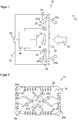
- FIG. 3 shows a detailed construction with the beam path of transmitted light 22a and illumination 22b on the deflection element 24 in cross section.
- the light source 20 is here an LED with lateral light exit, thus perpendicular to the viewing direction of the camera 10.
- the emission direction is preferably at least transversely to the viewing direction, ie, a slightly different from the orthogonal orientation angle range of for example 70 ° -110 ° is conceivable. This can be achieved, for example, with a light deflection at the light source 20 instead of a laterally emitting LED.
- the angle of incidence in the detection area 14 can also be flatter or steeper by means of a corresponding configuration of the deflecting element 24 than shown, depending on the distance and in what form a dark field illumination 22b is needed.
- the contour of the deflection element 24 is designed so that as much transmitted light 22a as possible is directed into the detection area 14.
- a concave, ie bundling contour is selected.
- parameters of the dark field illumination 22b can be set, such as working distance, angle of incidence, size and geometry of the detection region 14 or intensity distribution.
- the contour can also be designed as a freeform.
- Such optical effects can be achieved instead of a specific contour of the deflection element 24 or cooperatively by means of additional, not shown optical components between the light source 20 and deflecting element 24, which approximately the transmitted light 22a in the vertical direction of FIG. 3 focus and make bundled to hit the deflector 24.
- the front screen 32 can be provided with an optically functional structure, such as an embossed lens, a prism or a diffractive structure, which provides for further focusing or an additional change of the angle of incidence in the detection area 14.
- the deflecting element 24 with a reflecting surface by such with a diffusely scattering surface. Then no dark field illumination 22b, but a diffuse illumination 22b.
- the camera 10 supports changes between dark field illumination 22b and diffuse illumination 22b and / or an adaptation of the illumination parameters by a very simple conversion in which the deflection element 24 is replaced by a deflecting element 24 which is suitable for the new requirements.
- the deflecting element 24 is only releasably fixed in the camera 10.
- the deflecting element 24 or the removable frame is attached to the windshield 32 and thus forms a common component. Then, a change of the deflection element 24 and consequently between dark field illumination 22b and diffuse illumination 22b or an adaptation of illumination parameters is effected simply by replacing the front screen 32.
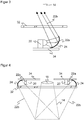
- FIG. 4 shows again a sectional view of the front portion of the camera 10 to illustrate the detection area 14 and the illuminated here with a dark field illumination 22b area. It is achieved a lateral Einstrahlwinkel, although the light sources 20 are even equipped in a plane.
- the gap between the shown sections of the printed circuit board 34 is due to the sectional view, but it may still be the same circuit board 34 with a central opening for the receiving light 12, as in the front view of FIG. 2 to recognize.
- FIG. 5 shows a possible application of the camera 10 in mounting on a conveyor belt 36, which promotes objects 38, as indicated by the arrow 40, through the detection area 14 of the camera 10.
- the objects 38 may carry code areas 42 on their outer surfaces.
- the task of the camera 10 is to detect properties of the objects 38 and, in a preferred use as a code reader, to recognize the code areas 42, to read out the codes applied there, to decode them and to assign them to the respectively associated object 38.
- additional, not shown cameras 10 are preferably used from different perspectives.
Landscapes
- Engineering & Computer Science (AREA)
- Physics & Mathematics (AREA)
- Multimedia (AREA)
- General Physics & Mathematics (AREA)
- Signal Processing (AREA)
- Theoretical Computer Science (AREA)
- Computer Vision & Pattern Recognition (AREA)
- Artificial Intelligence (AREA)
- Electromagnetism (AREA)
- Toxicology (AREA)
- General Health & Medical Sciences (AREA)
- Health & Medical Sciences (AREA)
- Quality & Reliability (AREA)
- Studio Devices (AREA)
- Investigating Materials By The Use Of Optical Means Adapted For Particular Applications (AREA)
- Stroboscope Apparatuses (AREA)
- Image Input (AREA)
- Length Measuring Devices By Optical Means (AREA)
Applications Claiming Priority (1)
| Application Number | Priority Date | Filing Date | Title |
|---|---|---|---|
| DE102018103544.6A DE102018103544B3 (de) | 2018-02-16 | 2018-02-16 | Kamera und Verfahren zur Erfassung von Bilddaten |
Publications (2)
| Publication Number | Publication Date |
|---|---|
| EP3528042A1 true EP3528042A1 (fr) | 2019-08-21 |
| EP3528042B1 EP3528042B1 (fr) | 2020-05-20 |
Family
ID=63679245
Family Applications (1)
| Application Number | Title | Priority Date | Filing Date |
|---|---|---|---|
| EP19152605.2A Active EP3528042B1 (fr) | 2018-02-16 | 2019-01-18 | Caméra et procédé de détection des données d'image |
Country Status (7)
| Country | Link |
|---|---|
| US (1) | US10878209B2 (fr) |
| EP (1) | EP3528042B1 (fr) |
| JP (1) | JP6912504B2 (fr) |
| KR (1) | KR102126422B1 (fr) |
| CN (1) | CN110166702B (fr) |
| DE (1) | DE102018103544B3 (fr) |
| DK (1) | DK3528042T3 (fr) |
Families Citing this family (6)
| Publication number | Priority date | Publication date | Assignee | Title |
|---|---|---|---|---|
| DE102019212988A1 (de) * | 2019-08-29 | 2021-03-04 | Audi Ag | Kameravorrichtung zum Erzeugen eines Abbilds einer Umgebung |
| US20220383404A1 (en) | 2019-10-25 | 2022-12-01 | Kyocera Corporation | Bid assistance system and bid assistance method |
| CN112824955B (zh) * | 2019-11-21 | 2022-06-28 | 江西欧迈斯微电子有限公司 | 结构光模组、成像装置及电子设备 |
| US11494576B2 (en) * | 2020-12-23 | 2022-11-08 | Hand Held Products, Inc. | Systems, methods, and apparatuses for imaging using a dual-purpose illuminator |
| DE102021100934A1 (de) | 2021-01-18 | 2022-07-21 | Ioss Intelligente Optische Sensoren & Systeme Gmbh | Verfahren und System zur Verifikation einer Oberflächenstruktur eines Objekts und passives Vorsatzmodul |
| DE102021100947B4 (de) * | 2021-01-19 | 2022-07-28 | Sick Ag | Kameravorrichtung und Verfahren zur Erfassung eines Objekts |
Citations (3)
| Publication number | Priority date | Publication date | Assignee | Title |
|---|---|---|---|---|
| US6614596B2 (en) * | 2001-07-25 | 2003-09-02 | Mitutoyo Corporation | Systems and methods for increasing illumination density within a field of view of an imaging system |
| US20030231494A1 (en) * | 2002-05-17 | 2003-12-18 | Mitutoyo Corporation | Ring illuminator |
| US7614563B1 (en) * | 2005-12-29 | 2009-11-10 | Cognex Technology And Investment Corporation | System and method for providing diffuse illumination in a symbology reader |
Family Cites Families (24)
| Publication number | Priority date | Publication date | Assignee | Title |
|---|---|---|---|---|
| JP3722547B2 (ja) * | 1996-04-08 | 2005-11-30 | オリンパス株式会社 | 照明光学系 |
| JP3593950B2 (ja) * | 1999-05-26 | 2004-11-24 | 株式会社デンソー | 二次元コード読取装置 |
| DE10026301A1 (de) | 2000-05-26 | 2001-11-29 | Sick Ag | Verfahren und Vorrichtung zur Bildverarbeitung |
| JP4035296B2 (ja) * | 2001-06-25 | 2008-01-16 | 京都電機器株式会社 | 照明装置 |
| NL1022891C2 (nl) * | 2003-03-11 | 2004-09-14 | Dental Innovaties B V | Belichtingsinrichting voor montage op een fototoestel met flitslamp. |
| US7604174B2 (en) | 2003-10-24 | 2009-10-20 | Cognex Technology And Investment Corporation | Method and apparatus for providing omnidirectional lighting in a scanning device |
| DE102005005536A1 (de) | 2005-02-07 | 2006-08-10 | Sick Ag | Codeleser |
| JP5523713B2 (ja) * | 2006-01-18 | 2014-06-18 | カプソ ビジョン, インコーポレイテッド | 生体内撮像システム |
| US7822335B1 (en) * | 2006-09-21 | 2010-10-26 | Microscan Systems, Inc. | Lens protector |
| CN101611308A (zh) * | 2006-09-27 | 2009-12-23 | 微扫描系统公司 | 用于通过包括三个不同的光反射区域的分光器对组件进行照明的设备和/或系统 |
| EP2247231A4 (fr) * | 2008-01-31 | 2011-08-10 | Applied Physiology Pty Ltd | Systèmes, procédés et dispositifs de maintenance, de guidage et/ou de commande |
| JP4716202B2 (ja) * | 2008-09-03 | 2011-07-06 | 株式会社デンソー | 撮像装置及び操作入力装置 |
| JP2010127897A (ja) * | 2008-12-01 | 2010-06-10 | Tech Vision:Kk | リング型照明装置 |
| US8768159B2 (en) | 2009-07-10 | 2014-07-01 | Microscan Systems, Inc. | Combination dark field and bright field illuminator |
| US10498933B2 (en) * | 2011-11-22 | 2019-12-03 | Cognex Corporation | Camera system with exchangeable illumination assembly |
| JP5989475B2 (ja) | 2012-09-19 | 2016-09-07 | 株式会社東芝 | 画像読取装置、及び紙葉類処理装置 |
| US9291877B2 (en) * | 2012-11-15 | 2016-03-22 | Og Technologies, Inc. | Method and apparatus for uniformly focused ring light |
| US9411212B2 (en) * | 2013-01-25 | 2016-08-09 | Canon Kabushiki Kaisha | Illumination apparatus which is arrangeable so as to surround an image capturing lens |
| EP2950519B1 (fr) * | 2014-05-26 | 2016-05-25 | Sick Ag | Caméra et procédé de capture de données d'image |
| WO2016088267A1 (fr) * | 2014-12-05 | 2016-06-09 | オリンパス株式会社 | Dispositif d'éclairage et endoscope |
| US9734374B2 (en) * | 2015-04-28 | 2017-08-15 | The Code Corporation | Barcode reader configured for fast image read-out |
| US20170078540A1 (en) * | 2015-09-02 | 2017-03-16 | Sick Ag | Camera for Recording Image Data From a Detection Zone |
| US9569653B1 (en) | 2016-06-13 | 2017-02-14 | Datalogic IP Tech, S.r.l. | Dark field illumination system obtained in a tilted plane |
| US10607316B2 (en) * | 2016-07-22 | 2020-03-31 | Panasonic Intellectual Property Management Co., Ltd. | Image generating apparatus and image generating method |
-
2018
- 2018-02-16 DE DE102018103544.6A patent/DE102018103544B3/de not_active Expired - Fee Related
-
2019
- 2019-01-18 DK DK19152605.2T patent/DK3528042T3/da active
- 2019-01-18 EP EP19152605.2A patent/EP3528042B1/fr active Active
- 2019-02-07 JP JP2019020712A patent/JP6912504B2/ja active Active
- 2019-02-12 CN CN201910111947.2A patent/CN110166702B/zh active Active
- 2019-02-14 US US16/275,391 patent/US10878209B2/en active Active
- 2019-02-14 KR KR1020190017288A patent/KR102126422B1/ko active IP Right Grant
Patent Citations (3)
| Publication number | Priority date | Publication date | Assignee | Title |
|---|---|---|---|---|
| US6614596B2 (en) * | 2001-07-25 | 2003-09-02 | Mitutoyo Corporation | Systems and methods for increasing illumination density within a field of view of an imaging system |
| US20030231494A1 (en) * | 2002-05-17 | 2003-12-18 | Mitutoyo Corporation | Ring illuminator |
| US7614563B1 (en) * | 2005-12-29 | 2009-11-10 | Cognex Technology And Investment Corporation | System and method for providing diffuse illumination in a symbology reader |
Also Published As
| Publication number | Publication date |
|---|---|
| DE102018103544B3 (de) | 2018-10-18 |
| EP3528042B1 (fr) | 2020-05-20 |
| JP6912504B2 (ja) | 2021-08-04 |
| JP2019194563A (ja) | 2019-11-07 |
| US20190258837A1 (en) | 2019-08-22 |
| DK3528042T3 (en) | 2020-07-13 |
| US10878209B2 (en) | 2020-12-29 |
| CN110166702B (zh) | 2021-01-22 |
| CN110166702A (zh) | 2019-08-23 |
| KR20190099136A (ko) | 2019-08-26 |
| KR102126422B1 (ko) | 2020-06-24 |
Similar Documents
| Publication | Publication Date | Title |
|---|---|---|
| DE102018103544B3 (de) | Kamera und Verfahren zur Erfassung von Bilddaten | |
| DE102013106585B4 (de) | System und Verfahren zur Feststellung der Brennweite einer Objektivanordnung | |
| DE10291122B4 (de) | Lesegerät mit einer Bildaufnahmeeinheit zum Lesen eines Codes und Verfahren zum Lesen eines Codes | |
| EP1985997B1 (fr) | Dispositif d'inspection pour récipients | |
| EP2950519B1 (fr) | Caméra et procédé de capture de données d'image | |
| EP3537334A1 (fr) | Caméra | |
| EP2916258B1 (fr) | Scanner de code barre 2d | |
| DE102017119282A1 (de) | Optische Abbildungsvorrichtungen und -verfahren | |
| DE102009058807A1 (de) | Sensor zur Prüfung von Wertdokumenten | |
| DE10159234B4 (de) | Vorrichtung zur Untersuchung von Dokumenten | |
| EP0270062B1 (fr) | Dispositif de prise d'image | |
| EP1483622B1 (fr) | Surface de support d'un appareil destine a la prise de vues optique d'objets | |
| DE112015001325T5 (de) | Beleuchtungsvorrichtung und Bild-Abtastvorrichtung | |
| EP3474529B1 (fr) | Éclairage pour la saisie de documents optique | |
| EP1130533B1 (fr) | Scanner | |
| DE102006012694B4 (de) | Optische Einrichtung zur Bildaufnahme | |
| DE202022104036U1 (de) | Codelesevorrichtung | |
| EP4300935A1 (fr) | Dispositif d'éclairage destiné à la génération d'un champ d'éclairage pour une caméra | |
| EP4310722A1 (fr) | Dispositif lecteur de code et indications d'un réglage de mise au point | |
| DE202022103565U1 (de) | Beleuchtungsvorrichtung zur Erzeugung eines Beleuchtungsfeldes für eine Kamera | |
| EP3850595B1 (fr) | Dispositif de détection optique d'au moins une partie d'un document et utilisation d'un tel dispositif | |
| DE202014102452U1 (de) | Kamera zur Aufnahme von Bilddaten | |
| DE102021114556A1 (de) | Kamera und Verfahren zur Erfassung von durch einen Erfassungsbereich bewegten Objekten | |
| DE202021103066U1 (de) | Kamera zur Erfassung von durch einen Erfassungsbereich bewegten Objekten | |
| EP3624073A1 (fr) | Lecteur de document destiné à la détection optique d'un document d'identification |
Legal Events
| Date | Code | Title | Description |
|---|---|---|---|
| PUAI | Public reference made under article 153(3) epc to a published international application that has entered the european phase |
Free format text: ORIGINAL CODE: 0009012 |
|
| STAA | Information on the status of an ep patent application or granted ep patent |
Free format text: STATUS: THE APPLICATION HAS BEEN PUBLISHED |
|
| AK | Designated contracting states |
Kind code of ref document: A1 Designated state(s): AL AT BE BG CH CY CZ DE DK EE ES FI FR GB GR HR HU IE IS IT LI LT LU LV MC MK MT NL NO PL PT RO RS SE SI SK SM TR |
|
| AX | Request for extension of the european patent |
Extension state: BA ME |
|
| STAA | Information on the status of an ep patent application or granted ep patent |
Free format text: STATUS: REQUEST FOR EXAMINATION WAS MADE |
|
| 17P | Request for examination filed |
Effective date: 20191206 |
|
| RBV | Designated contracting states (corrected) |
Designated state(s): AL AT BE BG CH CY CZ DE DK EE ES FI FR GB GR HR HU IE IS IT LI LT LU LV MC MK MT NL NO PL PT RO RS SE SI SK SM TR |
|
| GRAP | Despatch of communication of intention to grant a patent |
Free format text: ORIGINAL CODE: EPIDOSNIGR1 |
|
| STAA | Information on the status of an ep patent application or granted ep patent |
Free format text: STATUS: GRANT OF PATENT IS INTENDED |
|
| RAP1 | Party data changed (applicant data changed or rights of an application transferred) |
Owner name: SICK AG |
|
| INTG | Intention to grant announced |
Effective date: 20200211 |
|
| GRAS | Grant fee paid |
Free format text: ORIGINAL CODE: EPIDOSNIGR3 |
|
| GRAA | (expected) grant |
Free format text: ORIGINAL CODE: 0009210 |
|
| STAA | Information on the status of an ep patent application or granted ep patent |
Free format text: STATUS: THE PATENT HAS BEEN GRANTED |
|
| AK | Designated contracting states |
Kind code of ref document: B1 Designated state(s): AL AT BE BG CH CY CZ DE DK EE ES FI FR GB GR HR HU IE IS IT LI LT LU LV MC MK MT NL NO PL PT RO RS SE SI SK SM TR |
|
| REG | Reference to a national code |
Ref country code: GB Ref legal event code: FG4D Free format text: NOT ENGLISH |
|
| REG | Reference to a national code |
Ref country code: CH Ref legal event code: EP |
|
| REG | Reference to a national code |
Ref country code: DE Ref legal event code: R096 Ref document number: 502019000040 Country of ref document: DE |
|
| REG | Reference to a national code |
Ref country code: AT Ref legal event code: REF Ref document number: 1272987 Country of ref document: AT Kind code of ref document: T Effective date: 20200615 |
|
| REG | Reference to a national code |
Ref country code: DK Ref legal event code: T3 Effective date: 20200707 |
|
| REG | Reference to a national code |
Ref country code: SE Ref legal event code: TRGR |
|
| REG | Reference to a national code |
Ref country code: NL Ref legal event code: FP |
|
| REG | Reference to a national code |
Ref country code: LT Ref legal event code: MG4D |
|
| PG25 | Lapsed in a contracting state [announced via postgrant information from national office to epo] |
Ref country code: IS Free format text: LAPSE BECAUSE OF FAILURE TO SUBMIT A TRANSLATION OF THE DESCRIPTION OR TO PAY THE FEE WITHIN THE PRESCRIBED TIME-LIMIT Effective date: 20200920 Ref country code: GR Free format text: LAPSE BECAUSE OF FAILURE TO SUBMIT A TRANSLATION OF THE DESCRIPTION OR TO PAY THE FEE WITHIN THE PRESCRIBED TIME-LIMIT Effective date: 20200821 Ref country code: LT Free format text: LAPSE BECAUSE OF FAILURE TO SUBMIT A TRANSLATION OF THE DESCRIPTION OR TO PAY THE FEE WITHIN THE PRESCRIBED TIME-LIMIT Effective date: 20200520 Ref country code: NO Free format text: LAPSE BECAUSE OF FAILURE TO SUBMIT A TRANSLATION OF THE DESCRIPTION OR TO PAY THE FEE WITHIN THE PRESCRIBED TIME-LIMIT Effective date: 20200820 Ref country code: FI Free format text: LAPSE BECAUSE OF FAILURE TO SUBMIT A TRANSLATION OF THE DESCRIPTION OR TO PAY THE FEE WITHIN THE PRESCRIBED TIME-LIMIT Effective date: 20200520 Ref country code: PT Free format text: LAPSE BECAUSE OF FAILURE TO SUBMIT A TRANSLATION OF THE DESCRIPTION OR TO PAY THE FEE WITHIN THE PRESCRIBED TIME-LIMIT Effective date: 20200921 |
|
| PG25 | Lapsed in a contracting state [announced via postgrant information from national office to epo] |
Ref country code: RS Free format text: LAPSE BECAUSE OF FAILURE TO SUBMIT A TRANSLATION OF THE DESCRIPTION OR TO PAY THE FEE WITHIN THE PRESCRIBED TIME-LIMIT Effective date: 20200520 Ref country code: HR Free format text: LAPSE BECAUSE OF FAILURE TO SUBMIT A TRANSLATION OF THE DESCRIPTION OR TO PAY THE FEE WITHIN THE PRESCRIBED TIME-LIMIT Effective date: 20200520 Ref country code: LV Free format text: LAPSE BECAUSE OF FAILURE TO SUBMIT A TRANSLATION OF THE DESCRIPTION OR TO PAY THE FEE WITHIN THE PRESCRIBED TIME-LIMIT Effective date: 20200520 Ref country code: BG Free format text: LAPSE BECAUSE OF FAILURE TO SUBMIT A TRANSLATION OF THE DESCRIPTION OR TO PAY THE FEE WITHIN THE PRESCRIBED TIME-LIMIT Effective date: 20200820 |
|
| PG25 | Lapsed in a contracting state [announced via postgrant information from national office to epo] |
Ref country code: AL Free format text: LAPSE BECAUSE OF FAILURE TO SUBMIT A TRANSLATION OF THE DESCRIPTION OR TO PAY THE FEE WITHIN THE PRESCRIBED TIME-LIMIT Effective date: 20200520 |
|
| PG25 | Lapsed in a contracting state [announced via postgrant information from national office to epo] |
Ref country code: EE Free format text: LAPSE BECAUSE OF FAILURE TO SUBMIT A TRANSLATION OF THE DESCRIPTION OR TO PAY THE FEE WITHIN THE PRESCRIBED TIME-LIMIT Effective date: 20200520 Ref country code: ES Free format text: LAPSE BECAUSE OF FAILURE TO SUBMIT A TRANSLATION OF THE DESCRIPTION OR TO PAY THE FEE WITHIN THE PRESCRIBED TIME-LIMIT Effective date: 20200520 Ref country code: RO Free format text: LAPSE BECAUSE OF FAILURE TO SUBMIT A TRANSLATION OF THE DESCRIPTION OR TO PAY THE FEE WITHIN THE PRESCRIBED TIME-LIMIT Effective date: 20200520 Ref country code: SM Free format text: LAPSE BECAUSE OF FAILURE TO SUBMIT A TRANSLATION OF THE DESCRIPTION OR TO PAY THE FEE WITHIN THE PRESCRIBED TIME-LIMIT Effective date: 20200520 |
|
| REG | Reference to a national code |
Ref country code: DE Ref legal event code: R097 Ref document number: 502019000040 Country of ref document: DE |
|
| PG25 | Lapsed in a contracting state [announced via postgrant information from national office to epo] |
Ref country code: PL Free format text: LAPSE BECAUSE OF FAILURE TO SUBMIT A TRANSLATION OF THE DESCRIPTION OR TO PAY THE FEE WITHIN THE PRESCRIBED TIME-LIMIT Effective date: 20200520 Ref country code: SK Free format text: LAPSE BECAUSE OF FAILURE TO SUBMIT A TRANSLATION OF THE DESCRIPTION OR TO PAY THE FEE WITHIN THE PRESCRIBED TIME-LIMIT Effective date: 20200520 |
|
| PLBE | No opposition filed within time limit |
Free format text: ORIGINAL CODE: 0009261 |
|
| STAA | Information on the status of an ep patent application or granted ep patent |
Free format text: STATUS: NO OPPOSITION FILED WITHIN TIME LIMIT |
|
| 26N | No opposition filed |
Effective date: 20210223 |
|
| PG25 | Lapsed in a contracting state [announced via postgrant information from national office to epo] |
Ref country code: MC Free format text: LAPSE BECAUSE OF FAILURE TO SUBMIT A TRANSLATION OF THE DESCRIPTION OR TO PAY THE FEE WITHIN THE PRESCRIBED TIME-LIMIT Effective date: 20200520 |
|
| PG25 | Lapsed in a contracting state [announced via postgrant information from national office to epo] |
Ref country code: LU Free format text: LAPSE BECAUSE OF NON-PAYMENT OF DUE FEES Effective date: 20210118 |
|
| PG25 | Lapsed in a contracting state [announced via postgrant information from national office to epo] |
Ref country code: IE Free format text: LAPSE BECAUSE OF NON-PAYMENT OF DUE FEES Effective date: 20210118 |
|
| PGFP | Annual fee paid to national office [announced via postgrant information from national office to epo] |
Ref country code: FR Payment date: 20230123 Year of fee payment: 5 Ref country code: DK Payment date: 20230123 Year of fee payment: 5 |
|
| PGFP | Annual fee paid to national office [announced via postgrant information from national office to epo] |
Ref country code: SE Payment date: 20230123 Year of fee payment: 5 Ref country code: IT Payment date: 20230131 Year of fee payment: 5 Ref country code: BE Payment date: 20230123 Year of fee payment: 5 |
|
| PG25 | Lapsed in a contracting state [announced via postgrant information from national office to epo] |
Ref country code: CY Free format text: LAPSE BECAUSE OF FAILURE TO SUBMIT A TRANSLATION OF THE DESCRIPTION OR TO PAY THE FEE WITHIN THE PRESCRIBED TIME-LIMIT Effective date: 20200520 |
|
| PG25 | Lapsed in a contracting state [announced via postgrant information from national office to epo] |
Ref country code: HU Free format text: LAPSE BECAUSE OF FAILURE TO SUBMIT A TRANSLATION OF THE DESCRIPTION OR TO PAY THE FEE WITHIN THE PRESCRIBED TIME-LIMIT; INVALID AB INITIO Effective date: 20190118 |
|
| PG25 | Lapsed in a contracting state [announced via postgrant information from national office to epo] |
Ref country code: SI Free format text: LAPSE BECAUSE OF FAILURE TO SUBMIT A TRANSLATION OF THE DESCRIPTION OR TO PAY THE FEE WITHIN THE PRESCRIBED TIME-LIMIT Effective date: 20200520 |
|
| PGFP | Annual fee paid to national office [announced via postgrant information from national office to epo] |
Ref country code: NL Payment date: 20240123 Year of fee payment: 6 |
|
| PGFP | Annual fee paid to national office [announced via postgrant information from national office to epo] |
Ref country code: AT Payment date: 20240118 Year of fee payment: 6 |
|
| PG25 | Lapsed in a contracting state [announced via postgrant information from national office to epo] |
Ref country code: MK Free format text: LAPSE BECAUSE OF FAILURE TO SUBMIT A TRANSLATION OF THE DESCRIPTION OR TO PAY THE FEE WITHIN THE PRESCRIBED TIME-LIMIT Effective date: 20200520 |
|
| PGFP | Annual fee paid to national office [announced via postgrant information from national office to epo] |
Ref country code: DE Payment date: 20240119 Year of fee payment: 6 Ref country code: CZ Payment date: 20240105 Year of fee payment: 6 Ref country code: GB Payment date: 20240124 Year of fee payment: 6 Ref country code: CH Payment date: 20240202 Year of fee payment: 6 |