EP3527968A1 - Spectral characteristic acquiring apparatus, image forming apparatus, image forming system, image forming apparatus management system, and image forming apparatus management method - Google Patents
Spectral characteristic acquiring apparatus, image forming apparatus, image forming system, image forming apparatus management system, and image forming apparatus management method Download PDFInfo
- Publication number
- EP3527968A1 EP3527968A1 EP19153927.9A EP19153927A EP3527968A1 EP 3527968 A1 EP3527968 A1 EP 3527968A1 EP 19153927 A EP19153927 A EP 19153927A EP 3527968 A1 EP3527968 A1 EP 3527968A1
- Authority
- EP
- European Patent Office
- Prior art keywords
- image forming
- color
- color data
- unit
- spectral characteristic
- Prior art date
- Legal status (The legal status is an assumption and is not a legal conclusion. Google has not performed a legal analysis and makes no representation as to the accuracy of the status listed.)
- Granted
Links
Images







Classifications
-
- G—PHYSICS
- G01—MEASURING; TESTING
- G01J—MEASUREMENT OF INTENSITY, VELOCITY, SPECTRAL CONTENT, POLARISATION, PHASE OR PULSE CHARACTERISTICS OF INFRARED, VISIBLE OR ULTRAVIOLET LIGHT; COLORIMETRY; RADIATION PYROMETRY
- G01J3/00—Spectrometry; Spectrophotometry; Monochromators; Measuring colours
- G01J3/46—Measurement of colour; Colour measuring devices, e.g. colorimeters
- G01J3/52—Measurement of colour; Colour measuring devices, e.g. colorimeters using colour charts
- G01J3/524—Calibration of colorimeters
-
- G—PHYSICS
- G01—MEASURING; TESTING
- G01J—MEASUREMENT OF INTENSITY, VELOCITY, SPECTRAL CONTENT, POLARISATION, PHASE OR PULSE CHARACTERISTICS OF INFRARED, VISIBLE OR ULTRAVIOLET LIGHT; COLORIMETRY; RADIATION PYROMETRY
- G01J3/00—Spectrometry; Spectrophotometry; Monochromators; Measuring colours
- G01J3/02—Details
- G01J3/0202—Mechanical elements; Supports for optical elements
-
- G—PHYSICS
- G01—MEASURING; TESTING
- G01J—MEASUREMENT OF INTENSITY, VELOCITY, SPECTRAL CONTENT, POLARISATION, PHASE OR PULSE CHARACTERISTICS OF INFRARED, VISIBLE OR ULTRAVIOLET LIGHT; COLORIMETRY; RADIATION PYROMETRY
- G01J3/00—Spectrometry; Spectrophotometry; Monochromators; Measuring colours
- G01J3/28—Investigating the spectrum
- G01J3/2823—Imaging spectrometer
-
- G—PHYSICS
- G01—MEASURING; TESTING
- G01J—MEASUREMENT OF INTENSITY, VELOCITY, SPECTRAL CONTENT, POLARISATION, PHASE OR PULSE CHARACTERISTICS OF INFRARED, VISIBLE OR ULTRAVIOLET LIGHT; COLORIMETRY; RADIATION PYROMETRY
- G01J3/00—Spectrometry; Spectrophotometry; Monochromators; Measuring colours
- G01J3/46—Measurement of colour; Colour measuring devices, e.g. colorimeters
- G01J3/50—Measurement of colour; Colour measuring devices, e.g. colorimeters using electric radiation detectors
- G01J3/502—Measurement of colour; Colour measuring devices, e.g. colorimeters using electric radiation detectors using a dispersive element, e.g. grating, prism
-
- G—PHYSICS
- G01—MEASURING; TESTING
- G01N—INVESTIGATING OR ANALYSING MATERIALS BY DETERMINING THEIR CHEMICAL OR PHYSICAL PROPERTIES
- G01N21/00—Investigating or analysing materials by the use of optical means, i.e. using sub-millimetre waves, infrared, visible or ultraviolet light
- G01N21/17—Systems in which incident light is modified in accordance with the properties of the material investigated
- G01N21/25—Colour; Spectral properties, i.e. comparison of effect of material on the light at two or more different wavelengths or wavelength bands
- G01N21/251—Colorimeters; Construction thereof
-
- H—ELECTRICITY
- H04—ELECTRIC COMMUNICATION TECHNIQUE
- H04N—PICTORIAL COMMUNICATION, e.g. TELEVISION
- H04N1/00—Scanning, transmission or reproduction of documents or the like, e.g. facsimile transmission; Details thereof
- H04N1/00567—Handling of original or reproduction media, e.g. cutting, separating, stacking
- H04N1/0057—Conveying sheets before or after scanning
-
- H—ELECTRICITY
- H04—ELECTRIC COMMUNICATION TECHNIQUE
- H04N—PICTORIAL COMMUNICATION, e.g. TELEVISION
- H04N1/00—Scanning, transmission or reproduction of documents or the like, e.g. facsimile transmission; Details thereof
- H04N1/46—Colour picture communication systems
- H04N1/48—Picture signal generators
-
- H—ELECTRICITY
- H04—ELECTRIC COMMUNICATION TECHNIQUE
- H04N—PICTORIAL COMMUNICATION, e.g. TELEVISION
- H04N1/00—Scanning, transmission or reproduction of documents or the like, e.g. facsimile transmission; Details thereof
- H04N1/46—Colour picture communication systems
- H04N1/56—Processing of colour picture signals
- H04N1/60—Colour correction or control
-
- H—ELECTRICITY
- H04—ELECTRIC COMMUNICATION TECHNIQUE
- H04N—PICTORIAL COMMUNICATION, e.g. TELEVISION
- H04N1/00—Scanning, transmission or reproduction of documents or the like, e.g. facsimile transmission; Details thereof
- H04N1/46—Colour picture communication systems
- H04N1/56—Processing of colour picture signals
- H04N1/60—Colour correction or control
- H04N1/6027—Correction or control of colour gradation or colour contrast
-
- H—ELECTRICITY
- H04—ELECTRIC COMMUNICATION TECHNIQUE
- H04N—PICTORIAL COMMUNICATION, e.g. TELEVISION
- H04N1/00—Scanning, transmission or reproduction of documents or the like, e.g. facsimile transmission; Details thereof
- H04N1/46—Colour picture communication systems
- H04N1/56—Processing of colour picture signals
- H04N1/60—Colour correction or control
- H04N1/603—Colour correction or control controlled by characteristics of the picture signal generator or the picture reproducer
- H04N1/6033—Colour correction or control controlled by characteristics of the picture signal generator or the picture reproducer using test pattern analysis
-
- G—PHYSICS
- G01—MEASURING; TESTING
- G01N—INVESTIGATING OR ANALYSING MATERIALS BY DETERMINING THEIR CHEMICAL OR PHYSICAL PROPERTIES
- G01N21/00—Investigating or analysing materials by the use of optical means, i.e. using sub-millimetre waves, infrared, visible or ultraviolet light
- G01N21/17—Systems in which incident light is modified in accordance with the properties of the material investigated
- G01N21/25—Colour; Spectral properties, i.e. comparison of effect of material on the light at two or more different wavelengths or wavelength bands
- G01N21/255—Details, e.g. use of specially adapted sources, lighting or optical systems
Definitions
- the present invention relates to a spectral characteristic acquiring apparatus, an image forming apparatus, an image forming system, an image forming apparatus management system, and an image forming apparatus management method.
- a scanning colorimetric technique for two-dimensionally scanning a measurement object such as a color patch using a spectral sensor to measure the color of the measurement object (see, e.g., Japanese Unexamined Patent Publication No. 2003-014546 ).
- a linear bright light source that is capable of illuminating a wide range is required in order to accurately acquire spectral characteristics across the width of an image, and as such, an apparatus employing such technique may be rather expensive.
- the spectral sensor is used to perform two-dimensional scanning, and as such, it takes time to acquire spectral characteristics of a measurement object. Because spectral characteristics of color patches of 5000 to 10000 colors have to be acquired, it is impractical to apply this technique to an image of a multicolor printer using six or more colors, for example.
- An aspect of the present invention is directed to providing a low-cost spectral characteristic acquiring apparatus that uses a plurality of arrayed spectral sensors.
- a spectral characteristic acquiring apparatus includes a color data acquiring unit including a plurality of spectral sensors configured to receive reflected light from an object that has been irradiated with light to acquire color data of the object, a spectral characteristic calculating unit configured to estimate spectral characteristics of the object based on the acquired color data of the object using a preset transformation matrix, a first conveying unit configured to convey the object in a predetermined conveying direction, and a second conveying unit configured to convey the color data acquiring unit in a direction intersecting the predetermined conveying direction.
- the plurality of spectral sensors are arrayed in the predetermined conveying direction.
- an image carrying medium such as paper is illustrated as an example of an object of spectral characteristic acquisition, and such an object of spectral characteristic acquisition is simply referred to as "paper".
- solid arrows indicating X-axis, Y-axis, and Z-axis directions in the drawings respectively represent the width direction of the paper, the paper conveying direction, and a direction orthogonal to the X-Y plane.
- the X-axis direction is an example of "a direction intersecting a predetermined conveying direction”
- the Y-axis direction is an example of "a predetermined conveying direction”.
- FIG. 1 is a perspective view diagram illustrating an example configuration of a spectral characteristic acquiring apparatus according to the present embodiment.
- the spectral characteristic acquiring apparatus 10 includes a color data acquiring unit 20, a paper conveying unit 30, a paper detection sensor 41, a color data acquiring unit conveying unit 40, a calibration color target 50, and a control unit 300. Further, the color data acquiring unit 20 includes a line illuminating light source 60, a reducing imaging lens 70, and a spectroscopic unit 80. The color data acquiring unit 20 is an example of a color data acquiring unit. Further, the paper conveying unit 30 is an example of a "first conveying unit", and the color data acquiring unit conveying unit 40 is an example of a "second conveying unit".
- a sheet of paper 100 is conveyed in the Y-axis direction at a constant speed by the paper conveying unit 30.
- the paper conveying unit 30 may be configured by a nip roller having two rollers, for example.
- the paper conveying unit 30 conveys the paper 100 by nipping the paper 100 with a nip roller and rotating the nip roller.
- the paper detection sensor 41 detects that the paper 100 has been conveyed to the position of a color data acquiring region 21.
- the paper detection sensor 41 may irradiate the paper 100 with light and detect reflected light reflected by the paper 100 with a photodiode or the like. Based on the output of the paper detection sensor 41, a determination may be made that the paper 100 is located at the position of the color data acquiring region 21 from which the color data acquiring unit 20 acquires color data.
- the color data acquiring unit conveying unit 40 conveys the color data acquiring unit 20 in the paper width direction.
- the color data acquiring unit conveying unit 40 may be a conveying stage including a ball screw and a guide, for example.
- the calibration color target 50 is used when calibrating a transformation matrix that is used for calculating spectral characteristics. Note that the calibration color target 50 will be described in detail below.
- the spectral characteristic acquiring apparatus 10 can simultaneously acquire the spectral characteristics of a plurality of positions in the Y-axis direction within the color data acquiring region 21 of the paper 100.
- the line illuminating light source 60 illuminates the color data acquiring region 21 with linear light from a direction that is approximately 45 degrees with respect to the normal direction of the paper 100. Also, the line illuminating light source 60 illuminates an appropriate region with respect to the color data acquiring region 21 so that reflected light from a region of the paper 100 other than that at the color data acquiring region 21 does not enter the spectroscopic unit 80.
- the line illuminating light source 60 may be configured by a white LED (Light Emitting Diode) array having intensity across substantially the entire visible light region, for example.
- a fluorescent lamp such as a cold cathode fluorescent lamp or a lamp light source may also be used as the line illuminating light source 60.
- the line illuminating light source 60 is preferably a light source that emits light in a wavelength region required for spectroscopy and is capable of uniformly illuminating the entire color data acquiring region 21. Note that in some embodiments, a collimating lens for converging light emitted from the line illuminating light source 60 and irradiating the paper 100 with parallel light or convergent light may be added.
- the reducing imaging lens 70 is arranged so that its optical axis coincides with the normal direction of the paper 100 and has a function of imaging reflected light (i.e., reflected light beam) from the paper 100 on a plane of incidence of the spectroscopic unit 80 at a predetermined magnification. Note that by adding image-side telecentricity to the reducing imaging lens 70, the chief ray of the light beam incident on an image plane becomes substantially parallel to the optical axis.
- the reducing imaging lens 70 may be composed of a plurality of lenses.
- the chief ray of the light beam incident on the image plane may be easily made substantially parallel to the optical axis.
- the reducing imaging lens 70 does not have to be provided with image-side telecentricity. In such case, an effect similar to that described above may be obtained by adjusting the positional relationship between each pinhole of a pinhole array and each lens of a lens array in accordance with the inclination of the chief ray at each position on the image plane as described below.
- the spectroscopic unit 80 has a function of spectrally diffusing and reflecting light irradiated on the paper 100 and a function of outputting a signal receiving the dispersed light. Note that the spectroscopic unit 80 will be described in detail below with reference to FIG. 2 .
- the optical system illustrated in FIG. 1 is a so-called 45/0 optical system in which the illuminating light emitted from the line illuminating light source 60 is obliquely incident on the paper 100 at approximately 45 degrees with respect to the paper 100, and the spectroscopic unit 80 receives diffused light scattered from the paper 100 in the vertical direction by diffuse reflection.
- the configuration of the optical system is not limited to the example illustrated in FIG. 1 .
- a so-called 0/45 optical system may be used in which illuminating light emitted from the line illuminating light source 60 is vertically incident on the paper 100, and the spectroscopic unit 80 receives diffused light scattered from the paper 100 at 45 degrees.
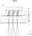
- FIG. 2 is an example cross-sectional view of the spectroscopic unit 80 according to the first embodiment. Specifically, FIG. 2 illustrates a partial cross section of the spectroscopic unit 80 that is parallel to the YZ plane of the spectroscopic unit 80.
- the spectroscopic unit 80 includes a pinhole array 81, a lens array 82, a diffraction element 83, and an imaging element 84. Further, the spectroscopic unit 80 includes a package 85, a spacer 86, a cover glass 87, and glass base materials 88a to 88c.
- the pinhole array 81 has pinholes as openings through which reflected light from the paper 100 passes.
- the pinholes are arranged at an image plane position in the Z-axis direction corresponding to where light incident from the reducing imaging lens 70 forms an image and are arranged at predetermined intervals in the Y-axis direction to form an array.
- FIG. 2 illustrates an example in which three pinholes are arranged in the Y-axis direction.
- the pinhole array 81 is integrally arranged on the glass base material 88a, which is a transparent flat glass plate provided as a light-transmissive frame.
- the pinhole array 81 may be configured by a metal thin film made of nickel or the like deposited on the transparent glass base material and having openings corresponding to pinholes arranged into an array. The light beams of reflected light from respective positions of the color data acquiring region 21 of the paper 100 are extracted by the pinholes arranged in the pinhole array 81.
- the configuration of the spectroscopic unit 80 is not limited to that using the pinhole array 81.
- a slit array having rectangular openings or an oblique slit array having rectangular slits inclined with respect to the Y-axis direction may also be used.
- the glass base material 88b which is a transparent flat glass plate provided as a light-transmissive frame, is bonded face-to-face with the surface of the glass base material 88a on the opposite side of the surface on which reflected light from the paper 100 is incident.
- the surface of the glass base material 88b on the opposite side of the bonding surface with the glass base material 88a has lenses arranged into an array at predetermined intervals in the Y-axis direction.
- FIG. 2 illustrates an example in which three lenses are arranged in the Y-axis direction to form the lens array 82.
- Each lens of the lens array 82 focuses a light beam that has passed through a pinhole of the pinhole array 81, and an image by each lens is formed on the imaging element 84.
- the lens array 82 has a plurality of lenses 82a arranged into one line extending in the Y-axis direction, and each lens 82a of the lens array 82 has the function of converting a diffused light beam that has passed through an opening of the pinhole array 81 into a weakly diffused light beam.
- a weakly diffused light beam refers to a diffused light beam that is closer to a parallel light beam than the incident diffused light beam. That is, a weakly diffused light beam refers to a diffused light beam whose degree of diffusion has been reduced, i.e., weakened, as compared with the incident diffused light beam.
- Each lens 82a of the lens array 82 is arranged at a position corresponding to an opening (pinhole) of the pinhole array 81.
- the diameter of each lens 82a is arranged so that all the light transmitted through its corresponding opening would be incident thereon. Note, however, that the planar shape of each lens 82a does not have to be circular.
- the glass base materials 88a and 88b are arranged between the pinhole array 81 and the lens array 82.
- the thicknesses of the glass base materials 88a and 88b are determined such that the optical path lengths of the pinhole array 81 and the lens array 82 are shorter than the object-side focal length of each lens 82a of the lens array 82. Note that portions of the lens array 82 other than the openings of the lenses 82a are preferably shielded in order to eliminate stray light.
- the glass base material 88c which is a transparent flat glass plate provided as a light-transmissive frame is arranged to face the lens array 82 in the Z-axis direction.
- the glass base material 88b and the glass base material 88c are bonded to each other via a spacer 86.
- the spacer 86 is a member for providing a predetermined space, i.e., a space between the glass base material 88b and the glass base material 88c.
- the spacer 86 may be a metal flat plate having a predetermined through hole formed in its flat portion. A portion of the spacer 86 that is facing the lens array 82 and does not correspond to the through hole and a portion of the glass base material 88 that does not have a lens formed thereon come into contact with each other and are bonded. Also, a portion of the spacer 86 that is facing the diffraction element 83 and does not correspond to the through hole and a portion of the glass base material 88b that does not have a lens formed there on come into contact with each other and are bonded.
- a predetermined gap i.e., a space
- the through hole of the spacer 86 may be a small hole for accommodating each lens of the lens array 82 or a large hole for accommodating a plurality of lenses of the lens array 82, for example.
- the diffraction element 83 is arranged on the surface of the glass base material 88c facing the lens array 82, i.e., the surface on which the reflected light from the paper 100 is incident.
- the diffraction element 83 has sawtooth-shaped structures formed at predetermined intervals on the glass base material 88c, and functions as a diffraction grating that diffracts and disperses incident light.
- the light beams transmitted through the respective lenses of the lens array 82 are dispersed by the diffraction element 83. Diffraction images corresponding to the light beams are formed on the imaging element 84.
- the diffraction element 83 is preferably a blazed diffraction grating with enhanced diffraction efficiency in the first diffraction order.
- a blazed diffraction grating as the diffraction element 83, only the diffraction efficiency in the first diffraction order can be enhanced, and in this way, the light utilization efficiency of the optical system can be enhanced. As a result, signals of sufficient quality can be acquired in a short time, and the time for acquiring spectral characteristics can be shortened.
- the imaging element 84 is a line sensor having a plurality of pixels arranged in the Y-axis direction.
- the imaging element 84 acquires the quantity of incident light of a predetermined wavelength band by having a plurality of light receiving elements arranged at different positions receive the respective diffraction images formed by the lens array 82 and the diffraction element 83.
- the imaging element 84 may be, for example, a MOS (Metal Oxide Semiconductor Device), a CMOS (Complementary Metal Oxide Semiconductor Device), a CCD (Charge Coupled Device), or the like.
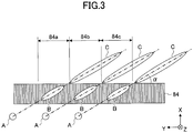
- the diffraction axis of the diffraction element 83 is inclined at an angle ⁇ with respect to the Y-axis direction.
- diffraction images inclined at the angle ⁇ with respect to the X-axis direction are incident on the imaging element 84.
- three diffraction patterns each consisting of a zero order diffraction image A, a first order diffraction image B, and a second order diffraction image C are arranged side by side in the Y-axis direction.
- the imaging element 84 is configured to receive the first order diffraction image B of each diffraction pattern.
- three primary diffraction images of three lens arrays are received at pixel regions 84a, 84b, and 84c of the imaging element 84 and converted into electric signals. The electric signals are output as color data acquired by the spectroscopic unit 80.
- the spectral characteristic acquiring apparatus 10 crosstalk of the diffraction images can be eliminated, and the spectral characteristic of the paper 100 can be obtained from the first order diffraction image B.
- the first order diffraction image B may be simply referred to as a "diffraction image”.
- the imaging element 84 is fixed inside the package 85, and an opening of the package 85 is closed with a transparent cover glass 87 that is provided as a light-transmissive frame.
- the cover glass 87 is bonded to the surface of the glass base material 88c on the opposite side of the surface on which the diffraction element 83 is formed.
- one pinhole of the pinhole array 81, one lens of the lens array 82 corresponding thereto, a part of the diffraction element 83, i.e., a part transmitting the light beam from the lens, and a part of the pixel array of the imaging element 84 implement the function of one spectrometer.
- a part of the spectroscopic unit 80 implementing the function of one spectroscope may be referred to as a spectral sensor.
- the number of spectral sensors is not particularly limited, and the spectroscopic unit 80 may be configured to have a large number of spectral sensors.
- the spectroscopic unit 80 may be configured to have a large number of spectral sensors.
- a 1024-pixel image sensor is used as the imaging element 84 and the number of pixels included in the above-described part of the pixel array of he imaging element 84 is 10 pixels, 102 spectral sensors may be provided.
- the spectral sensors may be arrayed in the Y-axis direction, i.e., the paper conveying direction, and are examples of "plurality of spectral sensors arrayed in the predetermined conveying direction".
- the pinhole array 81, the lens array 82, the diffraction element 83, and the imaging element 84 are stacked in the direction of the optical axis of the reducing imaging lens 70 and bonded together to form an integrated unit.
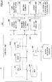
- FIG. 4 is a block diagram illustrating an example hardware configuration of the spectral characteristic acquiring apparatus 10 according to the present embodiment.
- the control unit 300 includes a main control unit 300A, an I/O (input/output) 305, a light source drive unit 306, an imaging element control unit 307, a motor drive unit 308, and a HDD (hard disk drive) 309.
- the main control unit 300A includes a CPU (central processing unit) 301, a ROM (read only memory) 302, and a RAM (random access memory) 303.
- the above elements are electrically connected to each other via a system bus 320.
- the CPU 301 comprehensively controls the operation of the spectral characteristic acquiring apparatus 10.
- the CPU 301 uses the RAM 303 as a work area to execute a program stored in the ROM 302 to thereby control the overall operation of the spectral characteristic acquiring apparatus 10 and implement various functions as described below.
- the HDD 309 stores acquired color data and the like.
- the I/O 305 inputs a signal detected by the paper detection sensor 41 and the like.
- the light source drive unit 306 is an electric circuit that outputs a drive signal such as a drive voltage for causing the line illuminating light source 60 to emit light in response to an input control signal.
- the imaging element control unit 307 controls imaging by the imaging element 84 of the spectroscopic unit 80 in response to an input control signal. Also, imaging data generated by the imaging element 84 is transmitted to the HDD 309 via the imaging element control unit 307 to be stored in the HDD 309 as color data.
- the motor drive unit 308 is an electric circuit that outputs drive signals such as drive voltages to respective motors for operating the paper conveying unit 30 and the color data acquiring unit conveying unit 40 in response to input control signals.
- the control unit 300 implements the function of estimating the spectral characteristics of the paper 100 based on acquired color data using a transformation matrix.
- a part or all of the control processes performed by the CPU 301 may be implemented by an electronic circuit such as an FPGA (Field-Programmable Gate Array) or an ASIC (Application Specific Integrated Circuit), for example.
- an electronic circuit such as an FPGA (Field-Programmable Gate Array) or an ASIC (Application Specific Integrated Circuit), for example.
- FIG. 5 is a block diagram illustrating an example functional configuration for spectral characteristic estimation computation.
- the control unit 300 includes a computing unit 110 and a storage unit 120.
- the computing unit 110 includes a color data input unit 111, a transformation matrix calculating unit 112, and a spectral characteristic calculating unit 113.
- the storage unit 120 includes a reference data storage unit 121, a color data storage unit 122, and a transformation matrix storage unit 123.
- the spectral characteristic acquiring apparatus 10 when light is irradiated from the line illuminating light source 60 onto the paper 100, an electric signal is output from the imaging element 84 of the spectroscopic unit 80 that has received a diffraction image, and the output electric signal is input to the color data input unit 111 as color data.
- the spectral characteristic calculating unit 113 calculates the spectral characteristic of the paper 100 based on the input color data using a transformation matrix stored in advance in the transformation matrix storage unit 123. Note that the spectral characteristic calculating unit 113 is an example of a "spectral characteristic calculating unit”.
- spectral characteristics may also be obtained through methods that differ from the method described below.
- a matrix r storing the spectral reflectance of each wavelength band e.g., wavelength range from 400 nm to 700 nm subdivided into 31 bands each with a 10-nm pitch
- the transformation matrix G is an example of a "preset transformation matrix".
- the transformation matrix G is obtained by minimizing the square of the norm ⁇ • ⁇ 2 of an error using the least squares method based on a matrix R storing spectral reflectance distributions of a plurality (n) of known reference samples and the matrix V storing color data v obtained from the reference samples by a spectral sensor as indicated by the following formulas (2) to (4).
- the result of acquiring the spectral reflectance of the reference samples is stored in advance in the reference data storage unit 121 of the control unit 300.
- the transformation matrix calculating unit 112 generates a matrix V ref based on the color data obtained from the reference samples by the spectral characteristic acquiring apparatus 10.
- the transformation matrix calculating unit 112 also generates a matrix R ref based on the spectral reflectance distribution of the reference samples stored in the reference data storage unit 121.
- the transformation matrix calculating unit 112 calculates the transformation matrix G based on the generated matrices V ref and R ref using the above formula (5).
- the transformation matrix G calculated by the transformation matrix calculating unit 112 is stored in the transformation matrix storage unit 123.
- the matrix V ref of color data obtained from the reference sample by the spectral characteristic acquiring apparatus 10 is stored in the color data storage unit 122 of the control unit 300.
- the spectral characteristic calculating unit 113 When estimating the spectral characteristics of the paper 100, the spectral characteristic calculating unit 113 first generates a matrix V exp from the color data of the paper 100 and acquires the transformation matrix G stored in the transformation matrix storage unit 123. By using the matrix V exp and the transformation matrix G, the spectral characteristic calculating unit 113 can estimate spectral characteristics R exp of the paper 100 using the formula (2).
- the plurality of reference samples used in calculating the transformation matrix G are preferably evenly selected from the color range (gamut) of a color space (e.g., XYZ color space or L*a*b* color space) that can be reproduced in a printed image.
- a color space e.g., XYZ color space or L*a*b* color space
- the spectral characteristics of an image formed on the paper 100 may be estimated with high accuracy, for example.
- the transformation matrix G is desirably obtained based on a small number of reference samples to the extent that the spectral characteristic estimation accuracy would not be substantially compromised.
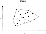
- FIG. 6 is a graph indicating the xy chromaticity of each reference sample of the 27 colors.
- each point represents the xy chromaticity of a reference sample
- the solid line represents the color reproduction range of a toner image.
- FIG. 6 illustrates how the reference samples are evenly selected from the color reproduction range of the toner image.
- the transformation matrix G calculated by the transformation matrix calculating unit 112 using the reference samples selected in the above-described manner is stored in advance in the transformation matrix storage unit 123.
- FIGS. 7A-7D are plan views of the paper 100 at the time of color data acquisition as viewed from the +Z-axis direction.
- FIGS. 7A-7D illustrate the paper 100 at different positions while being conveyed in the direction indicated by arrow 22 (i.e., +Y-axis direction).
- the color data acquiring unit 20 is positioned at the -X-axis direction end and the +Y-axis direction end of the paper 100.
- the color data acquiring unit 20 is continuously conveyed in direction 20a represented by the outlined arrow. Note that such continuous conveyance corresponds to a so-called scan drive.
- the spectroscopic unit 80 acquires color data of the color data acquiring region 21 of the paper 100 at predetermined time intervals.
- the predetermined time interval may be, for example, the frame period of the imaging element 84.
- conveyance of the paper 100 is stopped.
- conveyance of the color data acquiring unit 20 is stopped.
- the paper 100 is detected to be at the color data acquiring position based on the output of the paper detection sensor 41 when the paper 100 and the paper detection sensor 41 are the positional arrangement as illustrated in FIG. 7A .
- FIG. 7B illustrates the paper 100 after having been conveyed by a predetermined length in the Y-axis direction from the position illustrated in FIG. 7A .
- the predetermined length may be, for example, a length corresponding to the color data acquiring range of the spectroscopic unit 80 in the Y-axis direction.
- the color data acquiring unit 20 is located at the +X-axis direction end of the paper 100.
- the color data acquiring unit 20 is continuously conveyed in direction 20b represented by the outlined arrows. While the color data acquiring unit 20 is continuously conveyed, the spectroscopic unit 80 acquires the color data of the color data acquiring region 21 of the paper 100 at predetermined time intervals. At this time, the conveyance of the paper 100 is stopped in the same manner as described above. When the color data acquiring unit 20 is conveyed to the -X-axis direction end of the paper 100, the conveyance of the color data acquiring unit 20 is stopped.
- the color data acquiring unit 20 acquires color data of the color data acquiring region 21 of the paper 100 through similar operations in FIGS. 7C and 7D .
- the paper 100 is detected as having left the color data acquiring position based on the output of the paper detection sensor 41 when the paper 100 and the paper detection sensor 41 are in the positional arrangement as illustrated in FIG. 7D .
- color data of the entire region of the paper 100 can be acquired.
- the color data acquiring unit 20 is conveyed four times in the X-axis direction to acquire color data of the entire region of the paper 100.
- the number of times the color data acquiring unit 20 is conveyed is not limited to a particular number and may be suitably determined based on the size of the paper 100.
- step S801 the paper conveying unit 30 conveys the paper 100 in the Y-axis direction.
- step S803 the paper detection sensor 41 acquires a detection signal indicating whether the paper 100 is at the color data acquiring position, and outputs the detection signal to the control unit 300.
- step S805 the control unit 300 determines whether the paper 100 is located at the color data acquiring position based on the detection signal output by the paper detection sensor 41.
- step S805 If it is determined in step S805 that the paper 100 is located at the color data acquiring position, the process proceeds to step S807 in which the paper conveying unit 30 stops conveying the paper 100 in the Y-axis direction. On the other hand, if it is determined in step S805 that the paper 100 is not at the color data acquiring position, the process returns to step S803.
- step S809 the color data acquiring unit conveying unit 40 continuously conveys the color data acquiring unit 20 in the X-axis direction.
- step S811 the color data acquiring unit 20 acquires color data at predetermined time intervals. That is, the imaging element 84 of the color data acquiring unit 20 acquires diffraction images generated from reflected light from the color data acquiring region 21 and outputs the diffraction images as color data.
- step S813 the control unit 300 determines whether the color data acquiring unit 20 has been conveyed to the X-axis direction end of the paper 100. That is, the control unit 300 determines whether color data has been acquired across the entire X-axis direction color data acquiring range.
- step S813 If it is determined in step S813 that the color data acquiring unit 20 has been conveyed to the X-axis direction end of the paper 100, the process proceeds to step S815 in which the color data acquiring unit conveying unit 40 stops conveyance of the color data acquiring unit 20. If it is determined in step S813 that the color data acquiring unit 20 has not been conveyed to the X-axis direction end of the paper 100, the process returns to step S811.
- step S817 the paper conveying unit 30 conveys the paper 100 by a predetermined length in the Y-axis direction.
- step S819 the paper detection sensor 41 acquires a detection signal indicating whether the paper 100 is at the color data acquiring position, and outputs the detection signal to the control unit 300.
- step S821 the control unit 300 determines whether the paper 100 is at the color data acquiring position based on the detection signal output by the paper detection sensor 41.
- step S821 If it is determined in step S821 that the paper 100 is located at the color data acquiring position, the process returns to step S809 and the acquisition of color data is continued. On the other hand, if it is determined in step S821 that the paper 100 is not at the color data acquiring position, the process proceeds to step S823 in which the spectral characteristic calculating unit 113 calculates the spectral characteristics of the paper 100 based on the acquired color data using the transformation matrix G stored in the transformation matrix storage unit 123.
- the spectral characteristic acquiring process by the spectral characteristic acquiring apparatus 10 may be completed.
- the spectral characteristic acquiring apparatus 10 conveys the paper 100 and acquires color data of the entire region of the paper 100 by conveying the color data acquiring unit 20, which has a plurality of spectroscopic sensors arranged in the conveying direction of the paper 100, in the width direction of the paper 100.
- the calibration color target 50 is used for calibration of the transformation matrix.
- the transformation matrix stored in the transformation matrix storage unit 123 is calibrated using color data acquired by the color data acquiring unit 20 from the calibration color target 50.
- the calibration color target 50 is an example of a "calibration color target having a color target with known spectral characteristics".
- the calibration color target 50 has color regions in different colors that are preferably evenly selected from a color range that is reproducible in an image (i.e., gamut) of a color space such as the XYZ color space or the L*a*b color space, for example.
- the generation, maintenance, and measurement of the color regions of the calibration color target 50 require a substantial amount of time and costs. As such, a small number of color regions are preferably used to the extent that the estimation accuracy of spectral characteristics would not be compromised. In many cases, several to several tens of colors selected from the reproducible color range of image formation by an image forming apparatus are used. However, in order to increase the estimation accuracy of spectral characteristics and perform highly accurate measurement, several hundred to several thousand different colors may be required. Such a requirement is particularly relevant in the case where multicolor color materials of at least four colors are used for high image quality in image formation based on the electrophotographic method, the inkjet method, or the like, for example. Note that multicolor in the above context may include, for example, orange, green, white, clear, fluorescent colors, and the like, in addition to yellow, magenta, cyan, and black.
- reference samples of several colors to several thousands of colors selected from the color reproducible range of image formation by an image forming apparatus are used in the calibration color target 50.
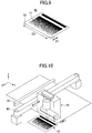
- FIG. 9 illustrates an example of the calibration color target 50 having such reference samples.
- the calibration color target 50 includes a plate member 52 formed by cutting a metal material such as aluminum, for example, and a plurality of color targets 51 provided on the upper surface of the plate member 52.
- the color targets 51 are band-shaped members that are colored by color-adjusted paint or the like.
- the width D1 and the length D2 of each band are arranged so that the band is at least the size of a color data acquiring range of the spectroscopic unit 80 at one time of conveyance.
- the width D1 of the band may be arranged to be at least 1 mm and the length D2 of the band may be arranged to be at least 100 mm.
- the calibration color target 50 is configured by arranging such color targets 51 side-by-side in the width direction on the plate member 52 so that their length directions (longitudinal directions) are substantially parallel to the conveying direction.
- the color targets 51 may be directly formed on the plate member 52, or color images may be formed on band-shaped paper which may then be attached to the plate member 52 as the color targets 51, for example.
- the plate member 52 is arranged to be large enough so that the color targets 51 would not be touched when held or conveyed. Note that when the color targets 51 are in a large number of different colors, the color targets 51 may be arranged on a plurality of plate members 52, for example.
- the calibration color target 50 is arranged adjacent to the paper 100 in the width direction of the paper 100 that is arranged within the conveyance range of the color data acquiring unit 20. That is, the calibration color target 50 is arranged within the conveyance range of the color data acquiring unit 20 conveyed by the color data acquiring unit conveying unit 40, at a region other than the region where the paper 100 is arranged. By conveying the color data acquiring unit 20 up to the position of the calibration color target 50, calibration using the calibration color target 50 may be performed.
- the spectral characteristics of the color targets 51 of the calibration color target 50 are measured in advance using a highly accurate spectroscope, and a matrix R 1 representing the spectral characteristics of the color regions is stored in advance in the reference data storage unit 121.
- each of the spectroscopic sensors included in the color data acquiring unit 20 has a transformation matrix G.
- the transformation matrix G of each spectroscopic sensor is calibrated by the transformation matrix calculating unit 112.
- the transformation matrix calculating unit 112 is an example of a "transformation matrix calibrating unit”.
- the color data acquiring unit 20 moves to the position of the calibration color target 50. Light is irradiated from the line illuminating light source 60 onto the calibration color target 50, and each spectral sensor of the color data acquiring unit 20 captures a diffraction image and outputs color data.
- the transformation matrix calculating unit 112 acquires, from the reference data storage unit 121, the matrix R ref representing the spectral characteristics of the reference samples measured in advance and the matrix R 1 representing the spectral characteristics of the color targets 51 of the calibration color target 50, and adds the matrix R 1 to the matrix R ref to obtain matrix R rev .
- the transformation matrix calculating unit 112 also adds a matrix V 1 of the color data obtained from the color targets 51 to the matrix V ref of the color data obtained from the reference samples stored in the color data storage unit 122 to obtain a matrix V rev .
- the transformation matrix calculating unit 112 obtains a transformation matrix G 1 using the above formula (5), and saves the calibrated transformation matrix G 1 in the transformation matrix storage unit 123.
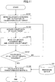
- FIG. 11 is a flowchart illustrating an example of the calibration process as described above.
- step S1101 the color data acquiring unit conveying unit 40 conveys the color data acquiring unit 20 in the width direction of the paper 100, and moves the color data acquiring unit 20 to the position of the color target 51 located at the end of the calibration color target 50.
- the color data acquiring unit 20 to the position may be moved to the position of the color target 51 at the -X-axis direction end of the calibration color target 50.
- step S1103 the color data acquiring unit 20 acquires the color data of the color target.
- step S1105 the color data acquiring unit conveying unit 40 conveys the color data acquiring unit 20 in the width direction to change the color target from which color data is to be acquired.
- step S1107 the control unit 300 determines whether color data of all the color targets have been acquired.
- step S1107 If it is determined in step S1107 that color data of all the color targets have been acquired, the process proceeds to step S1109 in which the transformation matrix calculating unit 112 obtains the transformation matrix G 1 using the above formula (5), and stores the calibrated transformation matrix G 1 in the transformation matrix storage unit 123.
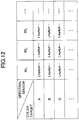
- FIG. 12 illustrates an example list of spectral characteristics acquired by each spectral sensor 80m in the color data acquiring unit 20 for each color target.
- step S1107 determines whether color data of all the color targets have been acquired. If it is determined in step S1107 that color data of all the color targets have not been acquired, the process returns to step S1103 to acquire color data of the next color target.
- the calibrated transformation matrix G 1 may be obtained.
- the spectral characteristic calculating unit 113 can estimate the spectral characteristics of the paper 100 more accurately.
- the color data acquiring unit 20 is conveyed in the width direction, and as such, even when an image formed on the paper 100 has a large width, color data of the entire width of the image can be acquired without using an expensive light source that can illuminate the entire width of the image at once.
- the spectral characteristic acquiring apparatus 10 according to the present embodiment that can acquire spectral characteristics with high accuracy without using an expensive light source may be provided at a low cost.
- spectral characteristics of the paper 100 across a wide range in the conveying direction may be acquired at once, for example. Further, by promoting cooperation between the conveyance of the color data acquiring unit 20 and the conveyance of the paper 100, spectral characteristics of wide area of the paper 100 may be promptly acquired.
- the calibration color target 50 is arranged within the conveyance range of the color data acquiring unit, at a region other than the region where the paper 100 is arranged. In this way, switching between spectral characteristic acquisition mode and calibration mode may be enabled by simply moving the color data acquiring unit 20. Thus, calibration may be easily performed without providing a complicated configuration or mechanism for mode switching.
- the color data acquiring unit conveying unit 40 that moves the color data acquiring unit 20 to the position of the calibration color target 50 is an example of a "mode switching unit".
- band-shaped color targets 51 such that their longitudinal directions are substantially parallel to the conveying direction of the paper 100, a plurality of the spectral sensors of the color data acquiring unit 20 may be calibrated at once and calibration may be efficiently performed.
- characteristics of the line illuminating light source 60 may change due to influences of environmental change such as temperature change or deterioration over time, and color data acquired by the color data acquiring unit 20 for the same paper 100 may change over time.
- the calibration color target 50 used by a spectral characteristic acquiring apparatus 10a includes a white color target and a black color target, and a correction coefficient calculating unit of the spectral characteristic acquiring apparatus 10a calculates a color data correction coefficient using these color targets.
- the spectral characteristic calculating unit 113 estimates the spectral characteristics of the paper 100 using acquired color data that is by multiplied by the color data correction coefficient obtained by the correction coefficient calculating unit so that the spectral characteristics may always be estimated with high accuracy irrespective of changes in the line illuminating light source 60 and the like.
- backing conditions are determined based on the purpose.
- black backing may be used for ISO compliance and calibration
- white backing may be used for color profile creation for printing.
- the term "backing" refers to the backing color at the time of measurement.
- a white color target corresponding to a color target that is entirely white is used as the white backing
- a black color target corresponding to a color target that is entirely black is used as the black backing.
- the white color target may be a white film, white printing paper or the like, for example
- the black color target may be a black film, black printing paper, or the like, for example.
- the white color target and the black color target are included in the plurality of color targets of the calibration color target 50.
- the color data acquiring unit 20 can acquire color data for obtaining the correction coefficient by moving to the position of the white color target or the black color target in the calibration color target 50.
- reference color data v wref and reference color data v bref respectively obtained from the white color target and the black color target are measured in advance and stored in the color data storage unit 122 as reference values.
- FIG. 13 illustrates an example functional configuration of the spectral characteristic acquiring apparatus 10a according to the present embodiment.
- the spectral characteristic acquiring apparatus 10a includes a control unit 300a that includes a calculating unit 110a including a correction coefficient calculating unit 114 and a storage unit 120a including a correction coefficient storage unit 124.
- the correction coefficient calculating unit 114 acquires color data v w and color data v b from the white color target and the black color target.
- the correction coefficient calculating unit 114 also acquires the reference color data v wref and the reference color data v bref from the color data storage unit 122.
- the correction coefficient calculating unit 114 calculates correction coefficients w and b using the following formulas (6) and (7).
- the correction coefficient calculating unit 114 stores the correction coefficients w and b in the correction coefficient storage unit 124.
- the spectral characteristic calculating unit 113 calculates corrected color data v' of the paper 100 using the correction coefficients w and b acquired from the correction coefficient storage unit 124, based on the following formulas (8) and (9).
- the spectral characteristic calculating unit 113 In the case of white backing, the spectral characteristic calculating unit 113 generates a matrix V exp based on the corrected color data v w ' based on the above formula (8), and estimates the spectral characteristics R exp of the paper 100 using the transformation matrix G stored in the transformation matrix storage unit 123 based on the above formula (1).
- the spectral characteristic calculating unit 113 In the case of black backing, the spectral characteristic calculating unit 113 generates a matrix V exp based on the corrected color data v b ' based on the above formula (9), and estimates the spectral characteristics R exp of the paper 100 using the transformation matrix G stored in the transformation matrix storage unit 123 based on the above formula (1).
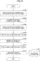
- FIG. 14 is a flowchart illustrating an example process of acquiring correction coefficients for color data.
- the color data acquiring unit conveying unit 40 moves the color data acquiring unit 20 to the position of the white color target of the calibration color target 50.
- step S1403 the color data acquiring unit 20 acquires color data v w of the white target.
- step S1405 the color data acquiring unit conveying unit 40 moves the color data acquiring unit 20 to the position of the black target of the calibration color target 50.
- step S1407 the control unit 300 turns off the line illuminating light source 60 via the light source drive unit 306.
- Dark current is the current that flows when light is not irradiated onto the pixels of the imaging element 84. For example, when the temperature rises by 7 °C to 10 °C, the dark current is approximately doubled.
- step S1409 the color data acquiring unit 20 acquires color data v b of the black target.
- step S1411 the control unit 300 turns on the line illuminating light source 60 via the light source drive unit 306.
- the line illuminating light source 60 is turned on at this time to prepare for the acquisition of the next color data.
- the correction coefficient calculating unit 114 refers to the color data storage unit 122 to acquire the reference color data v wref and the reference color data v bref , calculates correction coefficients w and b using the above formulas (6) and (7), and stores the calculated correction coefficients w and b in the correction coefficient storage unit 124.
- the spectral characteristic acquiring apparatus 10a can calculate and store the correction coefficients w and b using the white color target and the black color target.
- the white color target is an example of "white color target”
- the black color target is an example of "black color target”.
- color data output by the color data acquiring unit 20 is corrected so as to prevent degradation of spectral characteristic estimation accuracy caused by changes in the line illuminating light source 60 and the like. In this way, spectral characteristics may always be estimated with high accuracy.
- correction of changes occurring over a relatively short time period may serve as a simple calibration. According to the present embodiment, such simple calibration can be implemented without complicated operations.
- simple calibration has been described as a function separate from the spectral characteristic acquiring function.
- the simple calibration may alternatively be performed each time spectral characteristics are acquired as a part of the spectral characteristic acquiring process, for example. In this way, acquisition accuracy may always be ensured when acquiring spectral characteristics.
- an example image forming apparatus that includes the spectral characteristic acquiring apparatus according to the first embodiment or the second embodiment and is configured to acquire in-line spectral characteristics and adjust image forming conditions and the like will be described. Note that in the following description of the third embodiment, descriptions of features already described above in connection with the first embodiment or the second embodiment may be omitted.
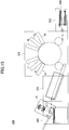
- FIG. 15 illustrates an example configuration of an image forming apparatus 200 according to the third embodiment.
- the image forming apparatus 200 is an inkjet image forming apparatus including the spectral characteristic acquiring apparatus 10, an image forming unit 201, a paper feeding unit 202, a drying unit 203, and a paper discharge unit 204.
- the image forming unit 201 has inkjet heads Gr, O, Y, M, Cy, and K arranged therein. Note that the symbols Gr, O, Y, M, Cy, and K represent ink colors of green, orange, yellow, magenta, cyan, and black, respectively.
- the paper feeding unit 202 of the image forming apparatus 200 accommodates sheets of the paper 100 corresponding to the object of spectral characteristic acquisition.
- the paper 100 may be fed in order from the uppermost sheet of paper 100 in the paper feeding unit 202 and conveyed to the image forming unit 201 at the appropriate timing by a pair of rollers, for example.
- the image forming unit 201 applies ink to the paper 100 using inkjet heads of corresponding colors to form a visible image based on image information. After ink is applied to the paper 100, the paper 100 is transported to the drying unit 203, and the ink is dried while the paper is conveyed across the drying unit 203. The dried paper 100 is then discharged by the paper discharge unit 204 or accommodated in a stacker.
- the spectral characteristic acquiring apparatus 10 is arranged in the paper discharge unit 204 so as to face an image surface of the paper 100.
- the image surface of the paper 100 is an example of a "recording medium surface”.
- the spectral characteristic acquiring apparatus 10 is used to conduct periodic inspections at the time the image forming apparatus 200 is activated, when the type of paper is changed, and/or when the image forming apparatus 200 is operated for a long time, for example.
- the spectral characteristic acquiring apparatus 10 acquires the spectral characteristics of the image data on the paper 100 while the paper 100 is being discharged and monitors color unevenness and color variations within the image formed on the paper surface.
- the data acquired by the spectral characteristic acquiring apparatus 10 is sent to a control unit of the image forming apparatus 200.
- the control unit functions as an image evaluating apparatus and adjusts image forming conditions such as the amount of ink applied by the inkjet heads and the like based on evaluation results for improving color reproducibility.
- the spectral characteristic acquiring apparatus 10 is used in the image forming apparatus 200.
- the spectral characteristic acquiring apparatus 10a according to the second embodiment may be used instead of the spectral characteristic acquiring apparatus 10, for example.
- image forming apparatus products are available on the market including printers, copying machines, multifunction peripherals as high added-value products having communication functions in addition to image forming functions, commercial printing machines, and the like.
- image forming methods are available including electrophotographic methods, inkjet methods, heat sensitive methods, and the like.
- a spectral characteristic acquiring apparatus such as a spectroscopic measurement apparatus or the like to acquire spectral characteristics of one or more points to perform calibration, for example.
- the spectral characteristic acquiring process is preferably carried out with respect to the entire region of the image formed by the image forming apparatus in order to appropriately respond to image fluctuations between pages and within a page.
- the spectral characteristic acquiring apparatus 10 is provided inside the image forming apparatus 200 in the above-described example, the spectral characteristic acquiring apparatus 10 may be provided separately from the image forming apparatus 200 to configure an image forming system, for example. That is, an image forming system that is capable of acquiring spectral characteristics offline and evaluating the acquired spectral characteristics may be configured.
- the image forming apparatus 200 may form images on one or more sheets of paper. Then, the sheets of paper having the images formed thereon may be brought to the position where the spectral characteristic acquiring apparatus 10 is located by a user, for example. Then, the spectral characteristic acquiring apparatus 10 may acquire the spectral characteristics of the image formed on each sheet of paper. The acquired spectral characteristics may then be fed back to the image forming apparatus 200 offline, and image forming conditions and imaging conditions of the image forming apparatus may be adjusted based thereon.
- an example image forming apparatus management system that includes the spectral characteristic acquiring apparatus according to the first embodiment or the second embodiment and is configured to manage an image forming apparatus will be described.
- descriptions of features that have already been described above in connection with the first embodiment or the second embodiment may be omitted.
- FIG. 16 illustrates an example configuration of an image forming apparatus management system 400 according to the present embodiment.
- the image forming apparatus management system 400 includes the spectral characteristic acquiring apparatus 10, a plurality of image forming apparatuses 401 1 to 401 x , and a management server 402.
- the image forming apparatuses 401 1 to 401 x are inkjet image forming apparatuses.
- the spectral characteristic acquiring apparatus 10 is used to conduct periodic image quality inspections of the image forming apparatuses 401 1 to 401 x when they are activated, when the paper type is changed, when they are operated for a long time, and the like.
- the spectral characteristic acquiring apparatus 10 acquires spectral characteristics of images respectively formed on paper 403 1 to 403 x by the image forming apparatuses 401 1 to 401 x and monitors color unevenness and color variations in the images formed by the image forming apparatuses 401 1 to 401 x .
- the image forming apparatuses 401 1 to 401 x form color patches 404 1 to 404 x as spectral characteristic acquisition images on the paper 403 1 to 403 x .
- the image forming apparatuses 401 1 to 401 x form color codes 405 1 to 405 x on pre-designated regions of the paper 403 1 to 403 x .
- the image forming apparatuses 401 1 to 401 x may be collectively referred to as “image forming apparatus 401".
- the paper 403 1 to 403 x may be collectively referred to as “paper 403”
- the color patches 404 1 to 404 x may be collectively be referred to as “color patch 404”
- the color codes 405 1 to 405 x may be collectively referred to as "color code 405".
- the color patch 404 has a plurality of different colored figures two-dimensionally arranged therein and is used as a color reference.
- the spectral characteristics of images formed by the image forming apparatuses 401 1 to 401 x can be evaluated.
- all of the color patches 404 1 to 404 x formed by the image forming apparatuses 401 1 to 401 x are the same.
- the acquired spectral characteristics of the color patches 404 1 to 404 x may be slightly different from each other.
- the color patch 404 is an example of a "predetermined pattern".
- the color code 405 includes colored figures for representing identification information.
- the color code 405 has the colored figures in unique colors one-dimensionally arranged into a row.
- FIG. 17 schematically illustrates an example of the color code 405.
- textures 405a to 405h represent colored figures in different colors.
- the color code 405 is an example of "identification information for identifying the image forming apparatus".
- the color of one colored figure may be represented by the mix ratio of red, blue, and green, for example.
- the mix ratio of red, blue, and green in hexadecimal digits and converting it into a numerical value, the color code 405 can be used as identification information including various items of information.
- Example items of information that may be represented by the color code 405 include the model name of the image forming apparatus 401, the product number of the image forming apparatus 401, the date/time the color code 405 was formed, the number of sheets of paper on which the color code 405 was formed, and the like.
- an overall size C1 of the color code 405 in the paper conveying direction is preferably set up so that the color code 405 would be within the color data acquiring range of the spectral characteristic acquiring apparatus 10.
- a size C2 of one colored figure in the color code 405 is preferably arranged to be greater than the color data acquiring range of one spectral sensor included in the color data acquiring unit 20.
- the paper 403 1 to 403 x on which the image forming apparatuses 401 1 to 401 x have formed images are passed to one spectral characteristic acquiring apparatus 10.
- the spectral characteristic acquiring apparatus 10 acquires the spectral characteristics of the color patches 404 1 to 404 x respectively formed on the paper 403 1 to 403 x .
- the spectral characteristic acquiring apparatus 10 acquires the spectral characteristics of the color codes 405 1 to 405 x respectively formed on the paper 403 1 to 403 x to acquire identification information.
- the spectral characteristic data and the identification information represented by the color codes 405 are associated with each other and stored in the management server 402.
- the management server 402 is an example of a "storage apparatus configured to store identification information for identifying an image forming apparatus and spectral characteristics of a pattern in association with each other".
- FIG. 18 is a flowchart illustrating example process steps of an image forming apparatus management method implemented by the image forming apparatus management system according to the present embodiment.
- an image forming apparatus 401 j forms a color patch 404 j on paper 403j.
- 'j' represents a natural number from 1 to x and may be a counter counting the number of image forming apparatuses 401 or a counter counting the number of sheets of paper 403.
- 'x' represents the number of image forming apparatuses 401 included in the image forming apparatus management system 400.
- step S1801 is an example of a "pattern forming step".
- step S1803 the image forming apparatus 401j forms a color code 405j on the paper 403j.
- step S1805 the counter j counting the number of image forming apparatuses 401 is incremented by one.
- the counter j may be performed by the management server 402, for example.
- the counter J may be updated by a user using the image forming apparatus, for example.
- step S1807 a determination is made as to whether j is less than or equal to x (j ⁇ x). That is, a determination is made as to whether all the image forming apparatuses 401 have formed color patches 404 and color codes 405 on paper 403. Such a determination may be made by the management server 402, for example. Alternatively, the determination may be made by the user using the image forming apparatus, for example.
- step S1807 If it is determined in step S1807 that j is less than or equal to x (j ⁇ x), the process returns to step S1801. On the other hand, if it is determined in step S1807 that j is not less than or equal to x, the process proceeds to step S1809 in which the spectral characteristic acquiring apparatus 10 acquires spectral characteristics of the color patch 404 j of the paper 403j.
- step S1811 the spectral characteristic acquiring apparatus 10 acquires the identification information represented by the color code 405j formed on the paper 403j.
- step S1813 the counter j counting the number of sheets of paper 403 is incremented by one.
- Such updating of the counter j may be performed by the management server 402, for example.
- the counter j may be updated by a user using the image forming apparatus, for example.
- step S1815 a determination is made as to whether j is less than or equal to x (j ⁇ x). That is, a determination is made as to whether the spectral characteristic acquiring apparatus 10 has acquired the spectral characteristics of all the color patches 404 and the identification information of all the color codes 405 of all the sheets of paper 403. Such a determination is made by the management server 402, for example. Alternatively, the determination may be made by the user using the image forming apparatus, for example.
- step S1815 If it is determined in step S1815, if it is determined that j is less than or equal to x (j ⁇ x), the process returns to step S1809. On the other hand, if it is determined in step S1815 that j is not less than or equal to x, the process proceeds to step S1817 in which the management server 402 stores the spectral characteristics of the color patches 404 and the identification information of the color codes 405 in association with each other. Note that step S1817 is an example of a "storage step".
- the spectral characteristics of the color patches 404 and the identification information of the color codes 405 are stored in association with each other in the management server 402.
- a user can refer to the management server 402 to check the spectral characteristic data of an image forming apparatus 401 identified by it corresponding identification information.
- the spectral characteristic data of each image forming apparatus 401 represented by its corresponding identification information may be acquired from the management server 402, and the image forming conditions of each image forming apparatus may be adjusted based on the acquired spectral characteristic data, for example.
- inkjet image forming apparatuses are being managed in the above-described example, the present embodiment may be applied to various types of image forming apparatuses including those using electrophotographic methods, for example.
- the spectral characteristic acquiring apparatus the image forming apparatus, the image forming system, the image forming apparatus management system, and the image forming apparatus management method according to the present invention have been described above with respect to certain illustrative embodiments, the present invention is not limited to the above-described embodiments and various modifications and changes may be made within the scope of the present invention.
Landscapes
- Physics & Mathematics (AREA)
- Spectroscopy & Molecular Physics (AREA)
- General Physics & Mathematics (AREA)
- Engineering & Computer Science (AREA)
- Multimedia (AREA)
- Signal Processing (AREA)
- Health & Medical Sciences (AREA)
- Life Sciences & Earth Sciences (AREA)
- Chemical & Material Sciences (AREA)
- Analytical Chemistry (AREA)
- Biochemistry (AREA)
- General Health & Medical Sciences (AREA)
- Immunology (AREA)
- Pathology (AREA)
- Spectrometry And Color Measurement (AREA)
- Control Or Security For Electrophotography (AREA)
Abstract
Description
- The present invention relates to a spectral characteristic acquiring apparatus, an image forming apparatus, an image forming system, an image forming apparatus management system, and an image forming apparatus management method.
- In recent years, high image quality is demanded in color images formed on recording media such as paper by full-color image forming apparatuses (printers, copiers, etc.) adopting the electrophotographic method, the inkjet method, and the like, and improvement of color reproducibility is one of the important technical challenges in the field.
- In order to improve color reproducibility, a technique is known for acquiring spectral characteristics of an image formed on a recording medium based on output signals obtained from a plurality of spectral sensors arranged in a direction orthogonal to the conveying direction of the recording medium (see, e.g., Japanese Patent No.
5880053 - Also, a scanning colorimetric technique is known for two-dimensionally scanning a measurement object such as a color patch using a spectral sensor to measure the color of the measurement object (see, e.g., Japanese Unexamined Patent Publication No.
2003-014546 - However, according to the technique described in Japanese Patent No.
5880053 2003-014546 - An aspect of the present invention is directed to providing a low-cost spectral characteristic acquiring apparatus that uses a plurality of arrayed spectral sensors.
- According to one embodiment of the present invention, a spectral characteristic acquiring apparatus is provided that includes a color data acquiring unit including a plurality of spectral sensors configured to receive reflected light from an object that has been irradiated with light to acquire color data of the object, a spectral characteristic calculating unit configured to estimate spectral characteristics of the object based on the acquired color data of the object using a preset transformation matrix, a first conveying unit configured to convey the object in a predetermined conveying direction, and a second conveying unit configured to convey the color data acquiring unit in a direction intersecting the predetermined conveying direction. The plurality of spectral sensors are arrayed in the predetermined conveying direction.
-
-
FIG. 1 is a perspective view diagram illustrating an example configuration of a spectral characteristic acquiring apparatus according to a first embodiment of the present invention; -
FIG. 2 is a diagram illustrating an example configuration of a spectroscopic unit of the spectral characteristic acquiring apparatus according to the first embodiment; -
FIG. 3 is a diagram illustrating diffraction images being received by an imaging element of the spectral characteristic acquiring apparatus according to the first embodiment; -
FIG. 4 is a block diagram illustrating an example hardware configuration of the spectral characteristic acquiring apparatus according to the first embodiment; -
FIG. 5 is a block diagram illustrating an example functional configuration for spectral characteristic estimation computation by the spectral characteristic acquiring apparatus according to the first embodiment; -
FIG. 6 is a diagram illustrating an example xy chromaticity distribution of reference samples and a color reproduction range of a toner image; -
FIGS. 7A-7D are plan views of a sheet viewed from the +Z axis direction while color data acquisition is performed by the spectral characteristic acquiring apparatus according to the first embodiment; -
FIG. 8 is a flowchart illustrating an example spectral characteristic acquiring process by the spectral characteristic acquiring apparatus according to the first embodiment; -
FIG. 9 is a diagram illustrating an example of a calibration color target of the spectral characteristic acquiring apparatus according to the first embodiment; -
FIG. 10 is a perspective view diagram illustrating an example disposition of the spectroscopic unit when calibration is performed by the spectral characteristic acquiring apparatus according to the first embodiment; -
FIG. 11 is a flowchart illustrating an example transformation matrix calibration process performed by the spectral characteristic acquiring apparatus according to the first embodiment; -
FIG. 12 is a diagram illustrating example spectral characteristics acquired for each color target by each spectral sensor of the spectral characteristic acquiring apparatus according to the first embodiment; -
FIG. 13 is a block diagram illustrating an example functional configuration for correction coefficient acquisition calculation by the spectral characteristic acquiring apparatus according to a second embodiment of the present invention; -
FIG. 14 is a flowchart illustrating an example correction coefficient acquiring process performed by the spectral characteristic acquiring apparatus according to the second embodiment; -
FIG. 15 is a diagram illustrating an example configuration of an image forming apparatus according to a third embodiment of the present invention; -
FIG. 16 is a diagram illustrating an example configuration of an image forming apparatus management system according to a fourth embodiment of the present invention; -
FIG. 17 is a diagram illustrating an example color code used in the image forming apparatus management system according to the fourth embodiment; and -
FIG. 18 is a flowchart illustrating an example process of an image forming apparatus management method implemented by the image forming apparatus management system according to the fourth embodiment. - In the following, embodiments of the present invention will be described with reference to the accompanying drawings. Note that in the drawings, elements having substantially the same features or configurations are given the same reference numerals and overlapping descriptions thereof may be omitted.
- Note that in the present description of embodiments, an image carrying medium such as paper is illustrated as an example of an object of spectral characteristic acquisition, and such an object of spectral characteristic acquisition is simply referred to as "paper". Also, note that solid arrows indicating X-axis, Y-axis, and Z-axis directions in the drawings respectively represent the width direction of the paper, the paper conveying direction, and a direction orthogonal to the X-Y plane. The X-axis direction is an example of "a direction intersecting a predetermined conveying direction", and the Y-axis direction is an example of "a predetermined conveying direction".
- Also, in the present description of embodiments, the terms "image formation", "recording", "printing", "shaping", and the like are all used synonymously.
- In the following, a first embodiment of the present invention will be described with reference to the drawings.
FIG. 1 is a perspective view diagram illustrating an example configuration of a spectral characteristic acquiring apparatus according to the present embodiment. - In
FIG. 1 , the spectralcharacteristic acquiring apparatus 10 includes a colordata acquiring unit 20, apaper conveying unit 30, apaper detection sensor 41, a color data acquiringunit conveying unit 40, acalibration color target 50, and acontrol unit 300. Further, the colordata acquiring unit 20 includes a lineilluminating light source 60, a reducingimaging lens 70, and aspectroscopic unit 80. The colordata acquiring unit 20 is an example of a color data acquiring unit. Further, thepaper conveying unit 30 is an example of a "first conveying unit", and the color data acquiringunit conveying unit 40 is an example of a "second conveying unit". - A sheet of
paper 100 is conveyed in the Y-axis direction at a constant speed by thepaper conveying unit 30. Thepaper conveying unit 30 may be configured by a nip roller having two rollers, for example. Thepaper conveying unit 30 conveys thepaper 100 by nipping thepaper 100 with a nip roller and rotating the nip roller. - The
paper detection sensor 41 detects that thepaper 100 has been conveyed to the position of a colordata acquiring region 21. For example, thepaper detection sensor 41 may irradiate thepaper 100 with light and detect reflected light reflected by thepaper 100 with a photodiode or the like. Based on the output of thepaper detection sensor 41, a determination may be made that thepaper 100 is located at the position of the colordata acquiring region 21 from which the colordata acquiring unit 20 acquires color data. - The color data acquiring
unit conveying unit 40 conveys the colordata acquiring unit 20 in the paper width direction. The color data acquiringunit conveying unit 40 may be a conveying stage including a ball screw and a guide, for example. - The
calibration color target 50 is used when calibrating a transformation matrix that is used for calculating spectral characteristics. Note that thecalibration color target 50 will be described in detail below. - The spectral
characteristic acquiring apparatus 10 can simultaneously acquire the spectral characteristics of a plurality of positions in the Y-axis direction within the colordata acquiring region 21 of thepaper 100. - The line illuminating
light source 60 illuminates the colordata acquiring region 21 with linear light from a direction that is approximately 45 degrees with respect to the normal direction of thepaper 100. Also, the line illuminatinglight source 60 illuminates an appropriate region with respect to the colordata acquiring region 21 so that reflected light from a region of thepaper 100 other than that at the colordata acquiring region 21 does not enter thespectroscopic unit 80. - The line
illuminating light source 60 may be configured by a white LED (Light Emitting Diode) array having intensity across substantially the entire visible light region, for example. However, the present invention is not limited thereto, and a fluorescent lamp such as a cold cathode fluorescent lamp or a lamp light source may also be used as the lineilluminating light source 60. - The line illuminating
light source 60 is preferably a light source that emits light in a wavelength region required for spectroscopy and is capable of uniformly illuminating the entire colordata acquiring region 21. Note that in some embodiments, a collimating lens for converging light emitted from the line illuminatinglight source 60 and irradiating thepaper 100 with parallel light or convergent light may be added. - The reducing
imaging lens 70 is arranged so that its optical axis coincides with the normal direction of thepaper 100 and has a function of imaging reflected light (i.e., reflected light beam) from thepaper 100 on a plane of incidence of thespectroscopic unit 80 at a predetermined magnification. Note that by adding image-side telecentricity to the reducingimaging lens 70, the chief ray of the light beam incident on an image plane becomes substantially parallel to the optical axis. The reducingimaging lens 70 may be composed of a plurality of lenses. - Note that by adding image-side telecentricity to the reducing
imaging lens 70, the chief ray of the light beam incident on the image plane may be easily made substantially parallel to the optical axis. However, the reducingimaging lens 70 does not have to be provided with image-side telecentricity. In such case, an effect similar to that described above may be obtained by adjusting the positional relationship between each pinhole of a pinhole array and each lens of a lens array in accordance with the inclination of the chief ray at each position on the image plane as described below. - The
spectroscopic unit 80 has a function of spectrally diffusing and reflecting light irradiated on thepaper 100 and a function of outputting a signal receiving the dispersed light. Note that thespectroscopic unit 80 will be described in detail below with reference toFIG. 2 . - Note that the optical system illustrated in
FIG. 1 is a so-called 45/0 optical system in which the illuminating light emitted from the line illuminatinglight source 60 is obliquely incident on thepaper 100 at approximately 45 degrees with respect to thepaper 100, and thespectroscopic unit 80 receives diffused light scattered from thepaper 100 in the vertical direction by diffuse reflection. However, the configuration of the optical system is not limited to the example illustrated inFIG. 1 . For example, a so-called 0/45 optical system may be used in which illuminating light emitted from the line illuminatinglight source 60 is vertically incident on thepaper 100, and thespectroscopic unit 80 receives diffused light scattered from thepaper 100 at 45 degrees. - In the following, the configuration of the
spectroscopic unit 80 will be described with reference toFIG. 2. FIG. 2 is an example cross-sectional view of thespectroscopic unit 80 according to the first embodiment. Specifically,FIG. 2 illustrates a partial cross section of thespectroscopic unit 80 that is parallel to the YZ plane of thespectroscopic unit 80. - In
FIG. 2 , thespectroscopic unit 80 includes apinhole array 81, alens array 82, a diffraction element 83, and animaging element 84. Further, thespectroscopic unit 80 includes apackage 85, aspacer 86, a cover glass 87, andglass base materials 88a to 88c. - The
pinhole array 81 has pinholes as openings through which reflected light from thepaper 100 passes. The pinholes are arranged at an image plane position in the Z-axis direction corresponding to where light incident from the reducingimaging lens 70 forms an image and are arranged at predetermined intervals in the Y-axis direction to form an array.FIG. 2 illustrates an example in which three pinholes are arranged in the Y-axis direction. - The
pinhole array 81 is integrally arranged on theglass base material 88a, which is a transparent flat glass plate provided as a light-transmissive frame. For example, thepinhole array 81 may be configured by a metal thin film made of nickel or the like deposited on the transparent glass base material and having openings corresponding to pinholes arranged into an array. The light beams of reflected light from respective positions of the colordata acquiring region 21 of thepaper 100 are extracted by the pinholes arranged in thepinhole array 81. - Note that the configuration of the
spectroscopic unit 80 is not limited to that using thepinhole array 81. For example, a slit array having rectangular openings or an oblique slit array having rectangular slits inclined with respect to the Y-axis direction may also be used. - The
glass base material 88b, which is a transparent flat glass plate provided as a light-transmissive frame, is bonded face-to-face with the surface of theglass base material 88a on the opposite side of the surface on which reflected light from thepaper 100 is incident. The surface of theglass base material 88b on the opposite side of the bonding surface with theglass base material 88a has lenses arranged into an array at predetermined intervals in the Y-axis direction.FIG. 2 illustrates an example in which three lenses are arranged in the Y-axis direction to form thelens array 82. Each lens of thelens array 82 focuses a light beam that has passed through a pinhole of thepinhole array 81, and an image by each lens is formed on theimaging element 84. - The
lens array 82 has a plurality of lenses 82a arranged into one line extending in the Y-axis direction, and each lens 82a of thelens array 82 has the function of converting a diffused light beam that has passed through an opening of thepinhole array 81 into a weakly diffused light beam. - Note that a weakly diffused light beam refers to a diffused light beam that is closer to a parallel light beam than the incident diffused light beam. That is, a weakly diffused light beam refers to a diffused light beam whose degree of diffusion has been reduced, i.e., weakened, as compared with the incident diffused light beam.
- Each lens 82a of the
lens array 82 is arranged at a position corresponding to an opening (pinhole) of thepinhole array 81. The diameter of each lens 82a is arranged so that all the light transmitted through its corresponding opening would be incident thereon. Note, however, that the planar shape of each lens 82a does not have to be circular. - In the present embodiment, the
glass base materials pinhole array 81 and thelens array 82. However, the present invention is not limited thereto. The thicknesses of theglass base materials pinhole array 81 and thelens array 82 are shorter than the object-side focal length of each lens 82a of thelens array 82. Note that portions of thelens array 82 other than the openings of the lenses 82a are preferably shielded in order to eliminate stray light. - The glass base material 88c, which is a transparent flat glass plate provided as a light-transmissive frame is arranged to face the
lens array 82 in the Z-axis direction. Theglass base material 88b and the glass base material 88c are bonded to each other via aspacer 86. - The
spacer 86 is a member for providing a predetermined space, i.e., a space between theglass base material 88b and the glass base material 88c. For example, thespacer 86 may be a metal flat plate having a predetermined through hole formed in its flat portion. A portion of thespacer 86 that is facing thelens array 82 and does not correspond to the through hole and a portion of the glass base material 88 that does not have a lens formed thereon come into contact with each other and are bonded. Also, a portion of thespacer 86 that is facing the diffraction element 83 and does not correspond to the through hole and a portion of theglass base material 88b that does not have a lens formed there on come into contact with each other and are bonded. In this way, a predetermined gap (i.e., a space) is provided between theglass base material 88b and the glass base material 88c. Note that the through hole of thespacer 86 may be a small hole for accommodating each lens of thelens array 82 or a large hole for accommodating a plurality of lenses of thelens array 82, for example. - The diffraction element 83 is arranged on the surface of the glass base material 88c facing the
lens array 82, i.e., the surface on which the reflected light from thepaper 100 is incident. The diffraction element 83 has sawtooth-shaped structures formed at predetermined intervals on the glass base material 88c, and functions as a diffraction grating that diffracts and disperses incident light. The light beams transmitted through the respective lenses of thelens array 82 are dispersed by the diffraction element 83. Diffraction images corresponding to the light beams are formed on theimaging element 84. - The diffraction element 83 is preferably a blazed diffraction grating with enhanced diffraction efficiency in the first diffraction order. By using a blazed diffraction grating as the diffraction element 83, only the diffraction efficiency in the first diffraction order can be enhanced, and in this way, the light utilization efficiency of the optical system can be enhanced. As a result, signals of sufficient quality can be acquired in a short time, and the time for acquiring spectral characteristics can be shortened.
- The
imaging element 84 is a line sensor having a plurality of pixels arranged in the Y-axis direction. Theimaging element 84 acquires the quantity of incident light of a predetermined wavelength band by having a plurality of light receiving elements arranged at different positions receive the respective diffraction images formed by thelens array 82 and the diffraction element 83. Theimaging element 84 may be, for example, a MOS (Metal Oxide Semiconductor Device), a CMOS (Complementary Metal Oxide Semiconductor Device), a CCD (Charge Coupled Device), or the like. - The diffraction axis of the diffraction element 83 is inclined at an angle α with respect to the Y-axis direction. As can be appreciated from
FIG. 3 , diffraction images inclined at the angle α with respect to the X-axis direction are incident on theimaging element 84. InFIG. 3 , three diffraction patterns each consisting of a zero order diffraction image A, a first order diffraction image B, and a second order diffraction image C are arranged side by side in the Y-axis direction. Theimaging element 84 is configured to receive the first order diffraction image B of each diffraction pattern. InFIG. 3 , three primary diffraction images of three lens arrays are received atpixel regions imaging element 84 and converted into electric signals. The electric signals are output as color data acquired by thespectroscopic unit 80. - As described above, in the spectral
characteristic acquiring apparatus 10, crosstalk of the diffraction images can be eliminated, and the spectral characteristic of thepaper 100 can be obtained from the first order diffraction image B. In the following description, the first order diffraction image B may be simply referred to as a "diffraction image". - The
imaging element 84 is fixed inside thepackage 85, and an opening of thepackage 85 is closed with a transparent cover glass 87 that is provided as a light-transmissive frame. The cover glass 87 is bonded to the surface of the glass base material 88c on the opposite side of the surface on which the diffraction element 83 is formed. - Note that optically speaking, one pinhole of the
pinhole array 81, one lens of thelens array 82 corresponding thereto, a part of the diffraction element 83, i.e., a part transmitting the light beam from the lens, and a part of the pixel array of theimaging element 84 implement the function of one spectrometer. As such, in the following description, a part of thespectroscopic unit 80 implementing the function of one spectroscope may be referred to as a spectral sensor. - Note that although only three spectral sensors are illustrated in
FIGS. 2 and3 , the number of spectral sensors is not particularly limited, and thespectroscopic unit 80 may be configured to have a large number of spectral sensors. For example, if a 1024-pixel image sensor is used as theimaging element 84 and the number of pixels included in the above-described part of the pixel array of he imagingelement 84 is 10 pixels, 102 spectral sensors may be provided. The spectral sensors may be arrayed in the Y-axis direction, i.e., the paper conveying direction, and are examples of "plurality of spectral sensors arrayed in the predetermined conveying direction". - In the optical system including the
spectroscopic unit 80, relative positional deviations between theimaging element 84 and the diffraction images formed by thepinhole array 81, thelens array 82, and the diffraction element 83 substantially influence the spectral characteristic acquisition accuracy. In the present embodiment, thepinhole array 81, thelens array 82, the diffraction element 83, and theimaging element 84 are stacked in the direction of the optical axis of the reducingimaging lens 70 and bonded together to form an integrated unit. - In the following, the
control unit 300 of the spectralcharacteristic acquiring apparatus 10 will be described with reference toFIG. 4. FIG. 4 is a block diagram illustrating an example hardware configuration of the spectralcharacteristic acquiring apparatus 10 according to the present embodiment. - The
control unit 300 includes amain control unit 300A, an I/O (input/output) 305, a lightsource drive unit 306, an imagingelement control unit 307, amotor drive unit 308, and a HDD (hard disk drive) 309. - The
main control unit 300A includes a CPU (central processing unit) 301, a ROM (read only memory) 302, and a RAM (random access memory) 303. The above elements are electrically connected to each other via asystem bus 320. - The
CPU 301 comprehensively controls the operation of the spectralcharacteristic acquiring apparatus 10. TheCPU 301 uses theRAM 303 as a work area to execute a program stored in theROM 302 to thereby control the overall operation of the spectralcharacteristic acquiring apparatus 10 and implement various functions as described below. TheHDD 309 stores acquired color data and the like. - The I/
O 305 inputs a signal detected by thepaper detection sensor 41 and the like. - The light
source drive unit 306 is an electric circuit that outputs a drive signal such as a drive voltage for causing the line illuminatinglight source 60 to emit light in response to an input control signal. - The imaging
element control unit 307 controls imaging by theimaging element 84 of thespectroscopic unit 80 in response to an input control signal. Also, imaging data generated by theimaging element 84 is transmitted to theHDD 309 via the imagingelement control unit 307 to be stored in theHDD 309 as color data. - The
motor drive unit 308 is an electric circuit that outputs drive signals such as drive voltages to respective motors for operating thepaper conveying unit 30 and the color data acquiringunit conveying unit 40 in response to input control signals. - The
control unit 300 implements the function of estimating the spectral characteristics of thepaper 100 based on acquired color data using a transformation matrix. - Note that in some embodiments, a part or all of the control processes performed by the
CPU 301 may be implemented by an electronic circuit such as an FPGA (Field-Programmable Gate Array) or an ASIC (Application Specific Integrated Circuit), for example. -
FIG. 5 is a block diagram illustrating an example functional configuration for spectral characteristic estimation computation. - The
control unit 300 includes acomputing unit 110 and astorage unit 120. Thecomputing unit 110 includes a colordata input unit 111, a transformationmatrix calculating unit 112, and a spectralcharacteristic calculating unit 113. Thestorage unit 120 includes a referencedata storage unit 121, a colordata storage unit 122, and a transformationmatrix storage unit 123. In the following, the functions of the above elements of thecomputing unit 110 and a method of estimating a spectral reflectance distribution as spectral characteristics of thepaper 100 will be described. - In the spectral
characteristic acquiring apparatus 10, when light is irradiated from the line illuminatinglight source 60 onto thepaper 100, an electric signal is output from theimaging element 84 of thespectroscopic unit 80 that has received a diffraction image, and the output electric signal is input to the colordata input unit 111 as color data. - When the color data is input, the spectral
characteristic calculating unit 113 calculates the spectral characteristic of thepaper 100 based on the input color data using a transformation matrix stored in advance in the transformationmatrix storage unit 123. Note that the spectralcharacteristic calculating unit 113 is an example of a "spectral characteristic calculating unit". - In the following, a method of estimating a spectral reflectance distribution as spectral characteristics based on color data output by one spectral sensor included in the
spectroscopic unit 80 will be described. Note, however, that spectral characteristics may also be obtained through methods that differ from the method described below. - Color data vi (i = 1 to N) is acquired from N pixels constituting one spectral sensor of the
spectroscopic unit 80, and the acquired color data vi is stored in a matrix V. Using the matrix V and a transformation matrix G, a matrix r storing the spectral reflectance of each wavelength band (e.g., wavelength range from 400 nm to 700 nm subdivided into 31 bands each with a 10-nm pitch) can be expressed by the following formula (1). Note that the transformation matrix G is an example of a "preset transformation matrix".
- The transformation matrix G is obtained by minimizing the square of the norm ∥ • ∥2 of an error using the least squares method based on a matrix R storing spectral reflectance distributions of a plurality (n) of known reference samples and the matrix V storing color data v obtained from the reference samples by a spectral sensor as indicated by the following formulas (2) to (4).


- The transformation matrix G, as a regression equation from V to R with V as the explanatory variable and R as the objective variable, can be expressed by the following formula (5) using the Moore-Penrose generalized inverse matrix that gives the square of the least-norm solution of the matrix V, for example. Note that in formula (5), the superscript T represents the transpose of the matrix, and the superscript -1 represents the inverse matrix.

- In the spectral
characteristic acquiring apparatus 10, the result of acquiring the spectral reflectance of the reference samples is stored in advance in the referencedata storage unit 121 of thecontrol unit 300. - The transformation
matrix calculating unit 112 generates a matrix Vref based on the color data obtained from the reference samples by the spectralcharacteristic acquiring apparatus 10. The transformationmatrix calculating unit 112 also generates a matrix Rref based on the spectral reflectance distribution of the reference samples stored in the referencedata storage unit 121. The transformationmatrix calculating unit 112 calculates the transformation matrix G based on the generated matrices Vref and Rref using the above formula (5). - The transformation matrix G calculated by the transformation
matrix calculating unit 112 is stored in the transformationmatrix storage unit 123. The matrix Vref of color data obtained from the reference sample by the spectralcharacteristic acquiring apparatus 10 is stored in the colordata storage unit 122 of thecontrol unit 300. - When estimating the spectral characteristics of the
paper 100, the spectralcharacteristic calculating unit 113 first generates a matrix Vexp from the color data of thepaper 100 and acquires the transformation matrix G stored in the transformationmatrix storage unit 123. By using the matrix Vexp and the transformation matrix G, the spectralcharacteristic calculating unit 113 can estimate spectral characteristics Rexp of thepaper 100 using the formula (2). - In the estimation computation described above, the plurality of reference samples used in calculating the transformation matrix G are preferably evenly selected from the color range (gamut) of a color space (e.g., XYZ color space or L*a*b* color space) that can be reproduced in a printed image. By using the transformation matrix G calculated based on such reference samples, the spectral characteristics of an image formed on the
paper 100 may be estimated with high accuracy, for example. - However, the generation, maintenance, and measurement of reference samples require a substantial amount of time and costs. As such, the transformation matrix G is desirably obtained based on a small number of reference samples to the extent that the spectral characteristic estimation accuracy would not be substantially compromised.
- For example, toner images of 27 colors evenly selected from the reproducible color range of an electrophotographic image forming apparatus may be used as the reference samples.
FIG. 6 is a graph indicating the xy chromaticity of each reference sample of the 27 colors. InFIG. 6 , each point represents the xy chromaticity of a reference sample, and the solid line represents the color reproduction range of a toner image.FIG. 6 illustrates how the reference samples are evenly selected from the color reproduction range of the toner image. - In the spectral
characteristic acquiring apparatus 10, the transformation matrix G calculated by the transformationmatrix calculating unit 112 using the reference samples selected in the above-described manner is stored in advance in the transformationmatrix storage unit 123. - In the following, operations of the color
data acquiring unit 20 and thepaper 100 at the time of color data acquisition by the spectralcharacteristic acquiring apparatus 10 will be described with reference toFIGS. 7A-7D. FIGS. 7A-7D are plan views of thepaper 100 at the time of color data acquisition as viewed from the +Z-axis direction.FIGS. 7A-7D illustrate thepaper 100 at different positions while being conveyed in the direction indicated by arrow 22 (i.e., +Y-axis direction). - In
FIG. 7A , the colordata acquiring unit 20 is positioned at the -X-axis direction end and the +Y-axis direction end of thepaper 100. Starting from the position indicated inFIG. 7A , the colordata acquiring unit 20 is continuously conveyed indirection 20a represented by the outlined arrow. Note that such continuous conveyance corresponds to a so-called scan drive. While the colordata acquiring unit 20 is continuously conveyed, thespectroscopic unit 80 acquires color data of the colordata acquiring region 21 of thepaper 100 at predetermined time intervals. The predetermined time interval may be, for example, the frame period of theimaging element 84. At this time, conveyance of thepaper 100 is stopped. When thespectroscopic unit 80 is conveyed to the +X-axis direction end of thepaper 100, conveyance of the colordata acquiring unit 20 is stopped. - Note that the
paper 100 is detected to be at the color data acquiring position based on the output of thepaper detection sensor 41 when thepaper 100 and thepaper detection sensor 41 are the positional arrangement as illustrated inFIG. 7A . -
FIG. 7B illustrates thepaper 100 after having been conveyed by a predetermined length in the Y-axis direction from the position illustrated inFIG. 7A . The predetermined length may be, for example, a length corresponding to the color data acquiring range of thespectroscopic unit 80 in the Y-axis direction. InFIG. 7B , the colordata acquiring unit 20 is located at the +X-axis direction end of thepaper 100. - Starting from the position illustrated in
FIG. 7B , the colordata acquiring unit 20 is continuously conveyed indirection 20b represented by the outlined arrows. While the colordata acquiring unit 20 is continuously conveyed, thespectroscopic unit 80 acquires the color data of the colordata acquiring region 21 of thepaper 100 at predetermined time intervals. At this time, the conveyance of thepaper 100 is stopped in the same manner as described above. When the colordata acquiring unit 20 is conveyed to the -X-axis direction end of thepaper 100, the conveyance of the colordata acquiring unit 20 is stopped. - The color
data acquiring unit 20 acquires color data of the colordata acquiring region 21 of thepaper 100 through similar operations inFIGS. 7C and 7D . - Note that the
paper 100 is detected as having left the color data acquiring position based on the output of thepaper detection sensor 41 when thepaper 100 and thepaper detection sensor 41 are in the positional arrangement as illustrated inFIG. 7D . - Through the operations as illustrated in
FIGS. 7A-7D , color data of the entire region of thepaper 100 can be acquired. Note that in the example described above, the colordata acquiring unit 20 is conveyed four times in the X-axis direction to acquire color data of the entire region of thepaper 100. However, the number of times the colordata acquiring unit 20 is conveyed is not limited to a particular number and may be suitably determined based on the size of thepaper 100. - In the following, an example spectral characteristic acquiring process implemented by the spectral
characteristic acquiring apparatus 10 will be described with reference toFIG. 8 . - First, in step S801, the
paper conveying unit 30 conveys thepaper 100 in the Y-axis direction. - Then, in step S803, the
paper detection sensor 41 acquires a detection signal indicating whether thepaper 100 is at the color data acquiring position, and outputs the detection signal to thecontrol unit 300. - Then, in step S805, the
control unit 300 determines whether thepaper 100 is located at the color data acquiring position based on the detection signal output by thepaper detection sensor 41. - If it is determined in step S805 that the
paper 100 is located at the color data acquiring position, the process proceeds to step S807 in which thepaper conveying unit 30 stops conveying thepaper 100 in the Y-axis direction. On the other hand, if it is determined in step S805 that thepaper 100 is not at the color data acquiring position, the process returns to step S803. - Then, in step S809, the color data acquiring
unit conveying unit 40 continuously conveys the colordata acquiring unit 20 in the X-axis direction. - Then, in step S811, the color
data acquiring unit 20 acquires color data at predetermined time intervals. That is, theimaging element 84 of the colordata acquiring unit 20 acquires diffraction images generated from reflected light from the colordata acquiring region 21 and outputs the diffraction images as color data. - Then, in step S813, the
control unit 300 determines whether the colordata acquiring unit 20 has been conveyed to the X-axis direction end of thepaper 100. That is, thecontrol unit 300 determines whether color data has been acquired across the entire X-axis direction color data acquiring range. - If it is determined in step S813 that the color
data acquiring unit 20 has been conveyed to the X-axis direction end of thepaper 100, the process proceeds to step S815 in which the color data acquiringunit conveying unit 40 stops conveyance of the colordata acquiring unit 20. If it is determined in step S813 that the colordata acquiring unit 20 has not been conveyed to the X-axis direction end of thepaper 100, the process returns to step S811. - Then, in step S817, the
paper conveying unit 30 conveys thepaper 100 by a predetermined length in the Y-axis direction. - Then, in step S819, the
paper detection sensor 41 acquires a detection signal indicating whether thepaper 100 is at the color data acquiring position, and outputs the detection signal to thecontrol unit 300. - Then, in step S821, the
control unit 300 determines whether thepaper 100 is at the color data acquiring position based on the detection signal output by thepaper detection sensor 41. - If it is determined in step S821 that the
paper 100 is located at the color data acquiring position, the process returns to step S809 and the acquisition of color data is continued. On the other hand, if it is determined in step S821 that thepaper 100 is not at the color data acquiring position, the process proceeds to step S823 in which the spectralcharacteristic calculating unit 113 calculates the spectral characteristics of thepaper 100 based on the acquired color data using the transformation matrix G stored in the transformationmatrix storage unit 123. - By implementing the above-described process operations, the spectral characteristic acquiring process by the spectral
characteristic acquiring apparatus 10 may be completed. - In this way, the spectral
characteristic acquiring apparatus 10 conveys thepaper 100 and acquires color data of the entire region of thepaper 100 by conveying the colordata acquiring unit 20, which has a plurality of spectroscopic sensors arranged in the conveying direction of thepaper 100, in the width direction of thepaper 100. - In the following, the calibration function of the spectral
characteristic acquiring apparatus 10 for calibrating the transformation matrix G according to the present embodiment will be described. Thecalibration color target 50 is used for calibration of the transformation matrix. The transformation matrix stored in the transformationmatrix storage unit 123 is calibrated using color data acquired by the colordata acquiring unit 20 from thecalibration color target 50. Thecalibration color target 50 is an example of a "calibration color target having a color target with known spectral characteristics". - The
calibration color target 50 has color regions in different colors that are preferably evenly selected from a color range that is reproducible in an image (i.e., gamut) of a color space such as the XYZ color space or the L*a*b color space, for example. - As described above in connection with the reference samples used for calculating the transformation matrix G, the generation, maintenance, and measurement of the color regions of the
calibration color target 50 require a substantial amount of time and costs. As such, a small number of color regions are preferably used to the extent that the estimation accuracy of spectral characteristics would not be compromised. In many cases, several to several tens of colors selected from the reproducible color range of image formation by an image forming apparatus are used. However, in order to increase the estimation accuracy of spectral characteristics and perform highly accurate measurement, several hundred to several thousand different colors may be required. Such a requirement is particularly relevant in the case where multicolor color materials of at least four colors are used for high image quality in image formation based on the electrophotographic method, the inkjet method, or the like, for example. Note that multicolor in the above context may include, for example, orange, green, white, clear, fluorescent colors, and the like, in addition to yellow, magenta, cyan, and black. - In the present embodiment, reference samples of several colors to several thousands of colors selected from the color reproducible range of image formation by an image forming apparatus are used in the
calibration color target 50.FIG. 9 illustrates an example of thecalibration color target 50 having such reference samples. - In
FIG. 9 , thecalibration color target 50 includes aplate member 52 formed by cutting a metal material such as aluminum, for example, and a plurality of color targets 51 provided on the upper surface of theplate member 52. The color targets 51 are band-shaped members that are colored by color-adjusted paint or the like. The width D1 and the length D2 of each band are arranged so that the band is at least the size of a color data acquiring range of thespectroscopic unit 80 at one time of conveyance. For example, when the color data acquiring range of thespectroscopic unit 80 is 1 mm in the width direction and 100 mm in the conveying direction, the width D1 of the band may be arranged to be at least 1 mm and the length D2 of the band may be arranged to be at least 100 mm. Thecalibration color target 50 is configured by arrangingsuch color targets 51 side-by-side in the width direction on theplate member 52 so that their length directions (longitudinal directions) are substantially parallel to the conveying direction. - The color targets 51 may be directly formed on the
plate member 52, or color images may be formed on band-shaped paper which may then be attached to theplate member 52 as the color targets 51, for example. Theplate member 52 is arranged to be large enough so that the color targets 51 would not be touched when held or conveyed. Note that when the color targets 51 are in a large number of different colors, the color targets 51 may be arranged on a plurality ofplate members 52, for example. - As illustrated in
FIG. 10 , thecalibration color target 50 is arranged adjacent to thepaper 100 in the width direction of thepaper 100 that is arranged within the conveyance range of the colordata acquiring unit 20. That is, thecalibration color target 50 is arranged within the conveyance range of the colordata acquiring unit 20 conveyed by the color data acquiringunit conveying unit 40, at a region other than the region where thepaper 100 is arranged. By conveying the colordata acquiring unit 20 up to the position of thecalibration color target 50, calibration using thecalibration color target 50 may be performed. - The spectral characteristics of the color targets 51 of the
calibration color target 50 are measured in advance using a highly accurate spectroscope, and a matrix R1 representing the spectral characteristics of the color regions is stored in advance in the referencedata storage unit 121. - In the following, a method of calibrating the transformation matrix G by the transformation
matrix calculating unit 112 will be described. Note that each of the spectroscopic sensors included in the colordata acquiring unit 20 has a transformation matrix G. The transformation matrix G of each spectroscopic sensor is calibrated by the transformationmatrix calculating unit 112. Note that the transformationmatrix calculating unit 112 is an example of a "transformation matrix calibrating unit". - When calibrating the transformation matrix G, the color
data acquiring unit 20 moves to the position of thecalibration color target 50. Light is irradiated from the line illuminatinglight source 60 onto thecalibration color target 50, and each spectral sensor of the colordata acquiring unit 20 captures a diffraction image and outputs color data. - First, the transformation
matrix calculating unit 112 acquires, from the referencedata storage unit 121, the matrix Rref representing the spectral characteristics of the reference samples measured in advance and the matrix R1 representing the spectral characteristics of the color targets 51 of thecalibration color target 50, and adds the matrix R1 to the matrix Rref to obtain matrix Rrev. The transformationmatrix calculating unit 112 also adds a matrix V1 of the color data obtained from the color targets 51 to the matrix Vref of the color data obtained from the reference samples stored in the colordata storage unit 122 to obtain a matrix Vrev. - Using the matrices Rrev and Vrev obtained in the above-described manner, the transformation
matrix calculating unit 112 obtains a transformation matrix G1 using the above formula (5), and saves the calibrated transformation matrix G1 in the transformationmatrix storage unit 123. -
FIG. 11 is a flowchart illustrating an example of the calibration process as described above. - First, in step S1101, the color data acquiring
unit conveying unit 40 conveys the colordata acquiring unit 20 in the width direction of thepaper 100, and moves the colordata acquiring unit 20 to the position of thecolor target 51 located at the end of thecalibration color target 50. For example, inFIG. 10 , the colordata acquiring unit 20 to the position may be moved to the position of thecolor target 51 at the -X-axis direction end of thecalibration color target 50. - Then, in step S1103, the color
data acquiring unit 20 acquires the color data of the color target. - Then, in step S1105, the color data acquiring
unit conveying unit 40 conveys the colordata acquiring unit 20 in the width direction to change the color target from which color data is to be acquired. - Then, in step S1107, the
control unit 300 determines whether color data of all the color targets have been acquired. - If it is determined in step S1107 that color data of all the color targets have been acquired, the process proceeds to step S1109 in which the transformation
matrix calculating unit 112 obtains the transformation matrix G1 using the above formula (5), and stores the calibrated transformation matrix G1 in the transformationmatrix storage unit 123.FIG. 12 illustrates an example list of spectral characteristics acquired by each spectral sensor 80m in the colordata acquiring unit 20 for each color target. - On the other hand, if it is determined in step S1107 that color data of all the color targets have not been acquired, the process returns to step S1103 to acquire color data of the next color target.
- In this way, the calibrated transformation matrix G1 may be obtained. By using the calibrated transformation matrix G1, the spectral
characteristic calculating unit 113 can estimate the spectral characteristics of thepaper 100 more accurately. - As described above, according to an aspect of the present embodiment, the color
data acquiring unit 20 is conveyed in the width direction, and as such, even when an image formed on thepaper 100 has a large width, color data of the entire width of the image can be acquired without using an expensive light source that can illuminate the entire width of the image at once. In this way, the spectralcharacteristic acquiring apparatus 10 according to the present embodiment that can acquire spectral characteristics with high accuracy without using an expensive light source may be provided at a low cost. - Further, by arranging a plurality of spectroscopic sensors in the conveying direction of the
paper 100, spectral characteristics of thepaper 100 across a wide range in the conveying direction may be acquired at once, for example. Further, by promoting cooperation between the conveyance of the colordata acquiring unit 20 and the conveyance of thepaper 100, spectral characteristics of wide area of thepaper 100 may be promptly acquired. - Also, by calibrating the transformation matrix using the
calibration color target 50, temporal changes in the spectral characteristic acquisition accuracy due to changes in air temperature, wavelength characteristics of the light source, and the like may be reduced. - Further, according to an aspect of the present embodiment, the
calibration color target 50 is arranged within the conveyance range of the color data acquiring unit, at a region other than the region where thepaper 100 is arranged. In this way, switching between spectral characteristic acquisition mode and calibration mode may be enabled by simply moving the colordata acquiring unit 20. Thus, calibration may be easily performed without providing a complicated configuration or mechanism for mode switching. Note that the color data acquiringunit conveying unit 40 that moves the colordata acquiring unit 20 to the position of thecalibration color target 50 is an example of a "mode switching unit". - Also, by arranging the band-shaped color targets 51 such that their longitudinal directions are substantially parallel to the conveying direction of the
paper 100, a plurality of the spectral sensors of the colordata acquiring unit 20 may be calibrated at once and calibration may be efficiently performed. - In the following, an example spectral characteristic acquiring apparatus according to a second embodiment of the present invention will be described. Note that features of the second embodiment that are substantially identical to those of the first embodiment are given the same reference numerals and their descriptions may be omitted.
- In the spectral characteristic acquiring apparatus, characteristics of the line illuminating
light source 60 may change due to influences of environmental change such as temperature change or deterioration over time, and color data acquired by the colordata acquiring unit 20 for thesame paper 100 may change over time. - In this respect, the
calibration color target 50 used by a spectral characteristic acquiringapparatus 10a according to the present embodiment includes a white color target and a black color target, and a correction coefficient calculating unit of the spectralcharacteristic acquiring apparatus 10a calculates a color data correction coefficient using these color targets. In the present embodiment, the spectralcharacteristic calculating unit 113 estimates the spectral characteristics of thepaper 100 using acquired color data that is by multiplied by the color data correction coefficient obtained by the correction coefficient calculating unit so that the spectral characteristics may always be estimated with high accuracy irrespective of changes in the line illuminatinglight source 60 and the like. - Note that backing conditions are determined based on the purpose. For example, black backing may be used for ISO compliance and calibration, and white backing may be used for color profile creation for printing. The term "backing" refers to the backing color at the time of measurement. A white color target corresponding to a color target that is entirely white is used as the white backing, and a black color target corresponding to a color target that is entirely black is used as the black backing. The white color target may be a white film, white printing paper or the like, for example, and the black color target may be a black film, black printing paper, or the like, for example. In the present embodiment, the white color target and the black color target are included in the plurality of color targets of the
calibration color target 50. Thus, the colordata acquiring unit 20 can acquire color data for obtaining the correction coefficient by moving to the position of the white color target or the black color target in thecalibration color target 50. - Note that reference color data vwref and reference color data vbref respectively obtained from the white color target and the black color target are measured in advance and stored in the color
data storage unit 122 as reference values. -
FIG. 13 illustrates an example functional configuration of the spectralcharacteristic acquiring apparatus 10a according to the present embodiment. The spectralcharacteristic acquiring apparatus 10a includes acontrol unit 300a that includes a calculatingunit 110a including a correctioncoefficient calculating unit 114 and astorage unit 120a including a correctioncoefficient storage unit 124. - The correction
coefficient calculating unit 114 acquires color data vw and color data vb from the white color target and the black color target. The correctioncoefficient calculating unit 114 also acquires the reference color data vwref and the reference color data vbref from the colordata storage unit 122. The correctioncoefficient calculating unit 114 calculates correction coefficients w and b using the following formulas (6) and (7).

- The correction
coefficient calculating unit 114 stores the correction coefficients w and b in the correctioncoefficient storage unit 124. - In the case of estimating the spectral characteristics of the
paper 100, when the spectralcharacteristic calculating unit 113 acquires color data v of thepaper 100, the spectralcharacteristic calculating unit 113 calculates corrected color data v' of thepaper 100 using the correction coefficients w and b acquired from the correctioncoefficient storage unit 124, based on the following formulas (8) and (9).

- In the case of white backing, the spectral
characteristic calculating unit 113 generates a matrix Vexp based on the corrected color data vw' based on the above formula (8), and estimates the spectral characteristics Rexp of thepaper 100 using the transformation matrix G stored in the transformationmatrix storage unit 123 based on the above formula (1). - In the case of black backing, the spectral
characteristic calculating unit 113 generates a matrix Vexp based on the corrected color data vb' based on the above formula (9), and estimates the spectral characteristics Rexp of thepaper 100 using the transformation matrix G stored in the transformationmatrix storage unit 123 based on the above formula (1). -
FIG. 14 is a flowchart illustrating an example process of acquiring correction coefficients for color data. First, in step S1401, the color data acquiringunit conveying unit 40 moves the colordata acquiring unit 20 to the position of the white color target of thecalibration color target 50. - Then, in step S1403, the color
data acquiring unit 20 acquires color data vw of the white target. - Then, in step S1405, the color data acquiring
unit conveying unit 40 moves the colordata acquiring unit 20 to the position of the black target of thecalibration color target 50. - Then, in step S1407, the
control unit 300 turns off the line illuminatinglight source 60 via the lightsource drive unit 306. Note that the line illuminatinglight source 60 is turned off in order to acquire output of color data from dark current. Dark current is the current that flows when light is not irradiated onto the pixels of theimaging element 84. For example, when the temperature rises by 7 °C to 10 °C, the dark current is approximately doubled. - Then, in step S1409, the color
data acquiring unit 20 acquires color data vb of the black target. - Then, in step S1411, the
control unit 300 turns on the line illuminatinglight source 60 via the lightsource drive unit 306. The line illuminatinglight source 60 is turned on at this time to prepare for the acquisition of the next color data. - Then, in step S1413, the correction
coefficient calculating unit 114 refers to the colordata storage unit 122 to acquire the reference color data vwref and the reference color data vbref, calculates correction coefficients w and b using the above formulas (6) and (7), and stores the calculated correction coefficients w and b in the correctioncoefficient storage unit 124. - In this way, the spectral
characteristic acquiring apparatus 10a can calculate and store the correction coefficients w and b using the white color target and the black color target. The white color target is an example of "white color target", and the black color target is an example of "black color target". - As described above, in the present embodiment, color data output by the color
data acquiring unit 20 is corrected so as to prevent degradation of spectral characteristic estimation accuracy caused by changes in the line illuminatinglight source 60 and the like. In this way, spectral characteristics may always be estimated with high accuracy. - Note that correction of changes occurring over a relatively short time period may serve as a simple calibration. According to the present embodiment, such simple calibration can be implemented without complicated operations.
- In the above description, simple calibration has been described as a function separate from the spectral characteristic acquiring function. However, because such simple calibration can be easily performed by moving the color
data acquiring unit 20, the simple calibration may alternatively be performed each time spectral characteristics are acquired as a part of the spectral characteristic acquiring process, for example. In this way, acquisition accuracy may always be ensured when acquiring spectral characteristics. - Note that other advantageous effects described above in connection with the first embodiment may similarly be obtained in the second embodiment.
- In the following, an example image forming apparatus that includes the spectral characteristic acquiring apparatus according to the first embodiment or the second embodiment and is configured to acquire in-line spectral characteristics and adjust image forming conditions and the like will be described. Note that in the following description of the third embodiment, descriptions of features already described above in connection with the first embodiment or the second embodiment may be omitted.
-
FIG. 15 illustrates an example configuration of animage forming apparatus 200 according to the third embodiment. - The
image forming apparatus 200 according to the present embodiment is an inkjet image forming apparatus including the spectralcharacteristic acquiring apparatus 10, animage forming unit 201, apaper feeding unit 202, adrying unit 203, and apaper discharge unit 204. Theimage forming unit 201 has inkjet heads Gr, O, Y, M, Cy, and K arranged therein. Note that the symbols Gr, O, Y, M, Cy, and K represent ink colors of green, orange, yellow, magenta, cyan, and black, respectively. - The
paper feeding unit 202 of theimage forming apparatus 200 accommodates sheets of thepaper 100 corresponding to the object of spectral characteristic acquisition. Thepaper 100 may be fed in order from the uppermost sheet ofpaper 100 in thepaper feeding unit 202 and conveyed to theimage forming unit 201 at the appropriate timing by a pair of rollers, for example. - The
image forming unit 201 applies ink to thepaper 100 using inkjet heads of corresponding colors to form a visible image based on image information. After ink is applied to thepaper 100, thepaper 100 is transported to thedrying unit 203, and the ink is dried while the paper is conveyed across the dryingunit 203. The driedpaper 100 is then discharged by thepaper discharge unit 204 or accommodated in a stacker. - The spectral
characteristic acquiring apparatus 10 is arranged in thepaper discharge unit 204 so as to face an image surface of thepaper 100. Note that the image surface of thepaper 100 is an example of a "recording medium surface". The spectralcharacteristic acquiring apparatus 10 is used to conduct periodic inspections at the time theimage forming apparatus 200 is activated, when the type of paper is changed, and/or when theimage forming apparatus 200 is operated for a long time, for example. The spectralcharacteristic acquiring apparatus 10 acquires the spectral characteristics of the image data on thepaper 100 while thepaper 100 is being discharged and monitors color unevenness and color variations within the image formed on the paper surface. - The data acquired by the spectral
characteristic acquiring apparatus 10 is sent to a control unit of theimage forming apparatus 200. The control unit functions as an image evaluating apparatus and adjusts image forming conditions such as the amount of ink applied by the inkjet heads and the like based on evaluation results for improving color reproducibility. - Note that in the above-described example, the spectral
characteristic acquiring apparatus 10 according to the first embodiment is used in theimage forming apparatus 200. However, the spectralcharacteristic acquiring apparatus 10a according to the second embodiment may be used instead of the spectralcharacteristic acquiring apparatus 10, for example. - Note that various types of image forming apparatus products are available on the market including printers, copying machines, multifunction peripherals as high added-value products having communication functions in addition to image forming functions, commercial printing machines, and the like. Also, various image forming methods are available including electrophotographic methods, inkjet methods, heat sensitive methods, and the like.
- Even in the field of production printing, digitization of both sheet-fed presses and continuous feed printers are progressing, and various products using electrophotographic methods and inkjet methods are available on the market.
- Also, there are increasing user needs for multidimensionality, high definition, and high density of images in view of the transition from monochrome printing to color printing. Further, with the diversification of services delivered to consumers, such as high-quality photographic printing, catalog printing, inclusion of personalized advertisement according to personal preferences in invoices and the like, there are growing demands for high image quality, personal information security, and color reproducibility.
- In the field of electrophotography, techniques are known for achieving higher image quality by installing a toner density sensor for detecting the toner density of toner before being fixed to an intermediate transfer medium or a photoreceptor to stabilize the toner supply amount.
- In the field of personal information security, regardless of the specific image forming method, techniques are known for inspecting images by capturing an output image with a camera or the like and performing character recognition or difference detection by inter-image difference calculation and the like.
- In the field of color reproduction, products are available on the market that uses a spectral characteristic acquiring apparatus such as a spectroscopic measurement apparatus or the like to acquire spectral characteristics of one or more points to perform calibration, for example.
- In the present embodiment, the spectral characteristic acquiring process is preferably carried out with respect to the entire region of the image formed by the image forming apparatus in order to appropriately respond to image fluctuations between pages and within a page.
- Note that although the spectral
characteristic acquiring apparatus 10 is provided inside theimage forming apparatus 200 in the above-described example, the spectralcharacteristic acquiring apparatus 10 may be provided separately from theimage forming apparatus 200 to configure an image forming system, for example. That is, an image forming system that is capable of acquiring spectral characteristics offline and evaluating the acquired spectral characteristics may be configured. - In this case, the
image forming apparatus 200 may form images on one or more sheets of paper. Then, the sheets of paper having the images formed thereon may be brought to the position where the spectralcharacteristic acquiring apparatus 10 is located by a user, for example. Then, the spectralcharacteristic acquiring apparatus 10 may acquire the spectral characteristics of the image formed on each sheet of paper. The acquired spectral characteristics may then be fed back to theimage forming apparatus 200 offline, and image forming conditions and imaging conditions of the image forming apparatus may be adjusted based thereon. - In the following, an example image forming apparatus management system according to a fourth embodiment of the present invention that includes the spectral characteristic acquiring apparatus according to the first embodiment or the second embodiment and is configured to manage an image forming apparatus will be described. In the following description of the fourth embodiment, descriptions of features that have already been described above in connection with the first embodiment or the second embodiment may be omitted.
-
FIG. 16 illustrates an example configuration of an image formingapparatus management system 400 according to the present embodiment. The image formingapparatus management system 400 includes the spectralcharacteristic acquiring apparatus 10, a plurality ofimage forming apparatuses 4011 to 401x, and amanagement server 402. - The
image forming apparatuses 4011 to 401x are inkjet image forming apparatuses. - The spectral
characteristic acquiring apparatus 10 is used to conduct periodic image quality inspections of theimage forming apparatuses 4011 to 401x when they are activated, when the paper type is changed, when they are operated for a long time, and the like. The spectralcharacteristic acquiring apparatus 10 acquires spectral characteristics of images respectively formed onpaper 4031 to 403x by theimage forming apparatuses 4011 to 401x and monitors color unevenness and color variations in the images formed by theimage forming apparatuses 4011 to 401x. - Upon image quality inspection, the
image forming apparatuses 4011 to 401xform color patches 4041 to 404x as spectral characteristic acquisition images on thepaper 4031 to 403x. In addition to forming thecolor patches 4041 to 404x, theimage forming apparatuses 4011 to 401xform color codes 4051 to 405x on pre-designated regions of thepaper 4031 to 403x. - In the following description, the
image forming apparatuses 4011 to 401x may be collectively referred to as "image forming apparatus 401". Also, thepaper 4031 to 403x may be collectively referred to as "paper 403", thecolor patches 4041 to 404x may be collectively be referred to as "color patch 404", and thecolor codes 4051 to 405x may be collectively referred to as "color code 405". - The
color patch 404 has a plurality of different colored figures two-dimensionally arranged therein and is used as a color reference. By acquiring the spectral characteristics of thecolor patches 4041 to 404x formed by theimage forming apparatuses 4011 to 401x, the spectral characteristics of images formed by theimage forming apparatuses 4011 to 401x can be evaluated. Ideally, all of thecolor patches 4041 to 404x formed by theimage forming apparatuses 4011 to 401x are the same. However, due to differences in image forming characteristics of theimage forming apparatuses 4011 to 401x, the acquired spectral characteristics of thecolor patches 4041 to 404x may be slightly different from each other. Note that thecolor patch 404 is an example of a "predetermined pattern". - The
color code 405 includes colored figures for representing identification information. Thecolor code 405 has the colored figures in unique colors one-dimensionally arranged into a row.FIG. 17 schematically illustrates an example of thecolor code 405. InFIG. 17 ,textures 405a to 405h represent colored figures in different colors. Note that thecolor code 405 is an example of "identification information for identifying the image forming apparatus". - Note that the color of one colored figure may be represented by the mix ratio of red, blue, and green, for example. Thus, for example, by expressing the mix ratio of red, blue, and green in hexadecimal digits and converting it into a numerical value, the
color code 405 can be used as identification information including various items of information. - Example items of information that may be represented by the
color code 405 include the model name of theimage forming apparatus 401, the product number of theimage forming apparatus 401, the date/time thecolor code 405 was formed, the number of sheets of paper on which thecolor code 405 was formed, and the like. - Note that an overall size C1 of the
color code 405 in the paper conveying direction is preferably set up so that thecolor code 405 would be within the color data acquiring range of the spectralcharacteristic acquiring apparatus 10. Also, a size C2 of one colored figure in thecolor code 405 is preferably arranged to be greater than the color data acquiring range of one spectral sensor included in the colordata acquiring unit 20. - The
paper 4031 to 403x on which theimage forming apparatuses 4011 to 401x have formed images are passed to one spectralcharacteristic acquiring apparatus 10. The spectralcharacteristic acquiring apparatus 10 acquires the spectral characteristics of thecolor patches 4041 to 404x respectively formed on thepaper 4031 to 403x. Also, the spectralcharacteristic acquiring apparatus 10 acquires the spectral characteristics of thecolor codes 4051 to 405x respectively formed on thepaper 4031 to 403x to acquire identification information. The spectral characteristic data and the identification information represented by thecolor codes 405 are associated with each other and stored in themanagement server 402. Note that themanagement server 402 is an example of a "storage apparatus configured to store identification information for identifying an image forming apparatus and spectral characteristics of a pattern in association with each other". -
FIG. 18 is a flowchart illustrating example process steps of an image forming apparatus management method implemented by the image forming apparatus management system according to the present embodiment. - First in step S1801, an
image forming apparatus 401j forms acolor patch 404j on paper 403j. Note that 'j' represents a natural number from 1 to x and may be a counter counting the number ofimage forming apparatuses 401 or a counter counting the number of sheets ofpaper 403. Also, 'x' represents the number ofimage forming apparatuses 401 included in the image formingapparatus management system 400. Note that step S1801 is an example of a "pattern forming step". - Then, in step S1803, the image forming apparatus 401j forms a color code 405j on the paper 403j.
- Then, in step S1805, the counter j counting the number of
image forming apparatuses 401 is incremented by one. Note that such updating of the counter j may be performed by themanagement server 402, for example. Alternatively, the counter J may be updated by a user using the image forming apparatus, for example. - Then, in step S1807, a determination is made as to whether j is less than or equal to x (j ≦ x). That is, a determination is made as to whether all the
image forming apparatuses 401 have formedcolor patches 404 andcolor codes 405 onpaper 403. Such a determination may be made by themanagement server 402, for example. Alternatively, the determination may be made by the user using the image forming apparatus, for example. - If it is determined in step S1807 that j is less than or equal to x (j ≦ x), the process returns to step S1801. On the other hand, if it is determined in step S1807 that j is not less than or equal to x, the process proceeds to step S1809 in which the spectral
characteristic acquiring apparatus 10 acquires spectral characteristics of thecolor patch 404j of the paper 403j. - Then, in step S1811, the spectral
characteristic acquiring apparatus 10 acquires the identification information represented by the color code 405j formed on the paper 403j. - Then, in step S1813, the counter j counting the number of sheets of
paper 403 is incremented by one. Such updating of the counter j may be performed by themanagement server 402, for example. Alternatively, the counter j may be updated by a user using the image forming apparatus, for example. - Then, in step S1815, a determination is made as to whether j is less than or equal to x (j ≦ x). That is, a determination is made as to whether the spectral
characteristic acquiring apparatus 10 has acquired the spectral characteristics of all thecolor patches 404 and the identification information of all thecolor codes 405 of all the sheets ofpaper 403. Such a determination is made by themanagement server 402, for example. Alternatively, the determination may be made by the user using the image forming apparatus, for example. - If it is determined in step S1815, if it is determined that j is less than or equal to x (j ≦ x), the process returns to step S1809. On the other hand, if it is determined in step S1815 that j is not less than or equal to x, the process proceeds to step S1817 in which the
management server 402 stores the spectral characteristics of thecolor patches 404 and the identification information of thecolor codes 405 in association with each other. Note that step S1817 is an example of a "storage step". - In this way, the spectral characteristics of the
color patches 404 and the identification information of thecolor codes 405 are stored in association with each other in themanagement server 402. - According to an aspect of the present embodiment, for example, a user can refer to the
management server 402 to check the spectral characteristic data of animage forming apparatus 401 identified by it corresponding identification information. Also, the spectral characteristic data of eachimage forming apparatus 401 represented by its corresponding identification information may be acquired from themanagement server 402, and the image forming conditions of each image forming apparatus may be adjusted based on the acquired spectral characteristic data, for example. - Note that although inkjet image forming apparatuses are being managed in the above-described example, the present embodiment may be applied to various types of image forming apparatuses including those using electrophotographic methods, for example.
- Although the spectral characteristic acquiring apparatus, the image forming apparatus, the image forming system, the image forming apparatus management system, and the image forming apparatus management method according to the present invention have been described above with respect to certain illustrative embodiments, the present invention is not limited to the above-described embodiments and various modifications and changes may be made within the scope of the present invention.
Claims (10)
- A spectral characteristic acquiring apparatus (10, 10a) comprising:a color data acquiring unit (20) including a plurality of spectral sensors configured to receive reflected light from an object (100) that has been irradiated with light to acquire color data of the object (100);a spectral characteristic calculating unit (113) configured to estimate spectral characteristics of the object (100) based on the acquired color data of the object (100) using a preset transformation matrix (G);a first conveying unit (30) configured to convey the object (100) in a predetermined conveying direction; anda second conveying unit (40) configured to convey the color data acquiring unit (20) in a direction intersecting the predetermined conveying direction;wherein the plurality of spectral sensors are arrayed in the predetermined conveying direction.
- The spectral characteristic acquiring apparatus (10, 10a) according to claim 1, further comprising:
a transformation matrix calibrating unit (112) configured to calibrate the transformation matrix (G) based on color data acquired from a calibration color target (50) including a color target (51) with known spectral characteristics. - The spectral characteristic acquiring apparatus (10, 10a) according to claim 1 or 2, further comprising:
a mode switching unit (40) configured to switch operation modes between a calibration mode for acquiring color data of a calibration color target (50) and a spectral characteristic acquisition mode for acquiring the color data of the object (100). - The spectral characteristic acquiring apparatus (10, 10a) according to claim 2, wherein
the object (100) is arranged within a conveyance range of the color data acquiring unit (20); and
the color target (51) of the calibration color target (50) is arranged within the conveyance range of the color data acquiring unit (20), at a region other than a region where the object (100) is arranged. - The spectral characteristic acquiring apparatus (10, 10a) according to claim 4, wherein
the color target (51) has a band-shaped configuration, and the color target (51) is arranged in the calibration color target (50) so that a longitudinal direction of the color target (51) is substantially parallel to the predetermined conveying direction. - The spectral characteristic acquiring apparatus (10, 10a) according to claim 2 or 3, wherein
the calibration color target (50) includes a white color target, a black color target, and a plurality of the color targets (51) in different colors. - An image forming apparatus (200) configured to change an image forming condition based on spectral characteristics of a recording medium surface, the image forming apparatus (200) comprising:
the spectral characteristic acquiring apparatus (10, 10a) according to any one of claims 1 to 6. - An image forming system comprising:an image forming apparatus (200) configured to change an image forming condition based on spectral characteristics of a recording medium surface; andthe spectral characteristic acquiring apparatus (10, 10a) according to any one of claims 1 to 6.
- An image forming apparatus management system (400) comprising:an image forming apparatus (401) configured to form a predetermined pattern (404) on a recording medium (403);the spectral characteristic acquiring apparatus (10, 10a) according to any one of claims 1 to 6 that is configured to acquire spectral characteristics of the predetermined pattern (404) formed by the image forming apparatus (401); anda storage apparatus (402) configured to store identification information for identifying the image forming apparatus (401) and the acquired spectral characteristics of the predetermined pattern (404) in association with each other.
- An image forming apparatus management method using the spectral characteristic acquiring apparatus (10, 10a) according to any one of claims 1 to 6, the image forming apparatus management method comprising:a pattern forming step of having an image forming apparatus (401) form a predetermined pattern (404) on a recording medium (403);a spectral characteristic acquisition step of having the spectral characteristic acquiring apparatus (10, 10a) acquire spectral characteristics of the predetermined pattern (404) formed by the image forming apparatus (401); anda storage step of storing identification information for identifying the image forming apparatus (401) and the acquired spectral characteristics of the predetermined pattern (404) in association with each other.
Applications Claiming Priority (1)
| Application Number | Priority Date | Filing Date | Title |
|---|---|---|---|
| JP2018025231A JP7095304B2 (en) | 2018-02-15 | 2018-02-15 | Spectral characteristic acquisition device, image forming device, image forming system, image forming device management system, and image forming device management method |
Publications (2)
| Publication Number | Publication Date |
|---|---|
| EP3527968A1 true EP3527968A1 (en) | 2019-08-21 |
| EP3527968B1 EP3527968B1 (en) | 2022-09-14 |
Family
ID=65268737
Family Applications (1)
| Application Number | Title | Priority Date | Filing Date |
|---|---|---|---|
| EP19153927.9A Active EP3527968B1 (en) | 2018-02-15 | 2019-01-28 | Spectral characteristic acquiring apparatus, image forming apparatus, image forming system, image forming apparatus management system, and image forming apparatus management method |
Country Status (3)
| Country | Link |
|---|---|
| US (1) | US10564038B2 (en) |
| EP (1) | EP3527968B1 (en) |
| JP (1) | JP7095304B2 (en) |
Cited By (1)
| Publication number | Priority date | Publication date | Assignee | Title |
|---|---|---|---|---|
| EP4585907A1 (en) * | 2024-01-15 | 2025-07-16 | Fyla Laser, S.L. | Optical apparatus, use of the apparatus, and optical method |
Families Citing this family (8)
| Publication number | Priority date | Publication date | Assignee | Title |
|---|---|---|---|---|
| JP2020153814A (en) | 2019-03-20 | 2020-09-24 | 株式会社リコー | Spectroscopic property acquisition device |
| US20220004828A1 (en) * | 2019-07-18 | 2022-01-06 | Hewlett-Packard Development Company, L.P. | Configuring color concentrations based on a white-point of print material |
| KR102464634B1 (en) * | 2019-12-06 | 2022-11-08 | 엘아이지넥스원 주식회사 | Method and Apparatus for Constructing Library construction for standardization of drawing creation and drawing creation using the Library |
| JP7585715B2 (en) | 2020-10-28 | 2024-11-19 | 株式会社リコー | Color chart, information processing device and information processing system |
| JP7661687B2 (en) | 2020-10-29 | 2025-04-15 | 株式会社リコー | Color chart, information processing device and information processing system |
| JP7473677B2 (en) * | 2020-11-16 | 2024-04-23 | グローリー株式会社 | Optical sensor, paper sheet identification device, paper sheet processing device, and optical detection method |
| US12301770B2 (en) | 2022-03-08 | 2025-05-13 | Ricoh Company, Ltd. | Information processing apparatus, abnormality detection method, storage medium, and information processing system |
| DE102022134187A1 (en) * | 2022-12-20 | 2024-06-20 | Manroland Goss Web Systems Gmbh | Device and method for the simultaneous determination of colour densities |
Citations (7)
| Publication number | Priority date | Publication date | Assignee | Title |
|---|---|---|---|---|
| EP0177461A2 (en) * | 1984-10-03 | 1986-04-09 | Ing. C. Olivetti & C., S.p.A. | Apparatus for reading graphic information displayed on a substrate |
| EP0831639A2 (en) * | 1996-09-23 | 1998-03-25 | Hewlett-Packard Company | Image device |
| JP2003014546A (en) | 2001-06-28 | 2003-01-15 | Minolta Co Ltd | Scanning colorimeter |
| EP2839966A1 (en) * | 2013-08-23 | 2015-02-25 | Seiko Epson Corporation | Liquid discharging apparatus and liquid discharging method |
| EP2916116A1 (en) * | 2014-02-20 | 2015-09-09 | Ricoh Company, Ltd. | Spectral characteristic acquisition device, image evaluation device, and image formation apparatus |
| US20150350493A1 (en) * | 2014-05-27 | 2015-12-03 | Konica Minolta, Inc. | Image reading apparatus and image forming apparatus |
| JP5880053B2 (en) | 2012-01-12 | 2016-03-08 | 株式会社リコー | Spectral characteristic acquisition apparatus and image forming apparatus |
Family Cites Families (22)
| Publication number | Priority date | Publication date | Assignee | Title |
|---|---|---|---|---|
| GB1440064A (en) | 1972-08-11 | 1976-06-23 | Glaxo Lab Ltd | Delta8-9- steroids of the pregnane series |
| JPS5880053A (en) | 1981-11-05 | 1983-05-14 | 三晃金属工業株式会社 | Heat insulating joint apparatus of panel for heat insulating large building |
| JP2002163089A (en) | 2000-11-24 | 2002-06-07 | Ricoh Co Ltd | Image forming system |
| US7492860B2 (en) | 2006-04-04 | 2009-02-17 | Ge Security, Inc. | Apparatus and method for controlling start and stop operations of a computed tomography imaging system |
| JP4985061B2 (en) | 2007-04-06 | 2012-07-25 | 株式会社ニコン | Spectroscopic apparatus and imaging apparatus |
| JP5440110B2 (en) | 2009-03-30 | 2014-03-12 | 株式会社リコー | Spectral characteristic acquisition apparatus, spectral characteristic acquisition method, image evaluation apparatus, and image forming apparatus |
| JP2011013201A (en) | 2009-07-03 | 2011-01-20 | Yoji Shindo | Tristimulus-value direct-reading type colorimetric device, colorimetric method therefor, and calibration method therefor |
| JP5655437B2 (en) | 2009-09-14 | 2015-01-21 | 株式会社リコー | Spectral characteristics acquisition device |
| JP5609068B2 (en) | 2009-11-04 | 2014-10-22 | 株式会社リコー | Spectrometer, image evaluation apparatus, and image forming apparatus |
| JP5609611B2 (en) | 2010-03-11 | 2014-10-22 | 株式会社リコー | Spectral characteristic acquisition device, image evaluation device, and image forming device |
| JP5605687B2 (en) | 2010-06-29 | 2014-10-15 | 株式会社リコー | Spectral characteristic measuring method, spectral characteristic measuring apparatus, and image forming apparatus having the same |
| JP5884347B2 (en) | 2011-09-12 | 2016-03-15 | 株式会社リコー | Spectral characteristic acquisition apparatus, spectral characteristic acquisition method, image evaluation apparatus, and image forming apparatus |
| JP5834938B2 (en) * | 2012-01-17 | 2015-12-24 | 株式会社リコー | Spectral characteristic acquisition apparatus, image evaluation apparatus, image forming apparatus, and spectral characteristic acquisition method |
| JP5910989B2 (en) | 2012-03-09 | 2016-04-27 | 株式会社リコー | Spectroscopic measurement apparatus, image evaluation apparatus, and image forming apparatus |
| JP6051543B2 (en) | 2012-03-09 | 2016-12-27 | 株式会社リコー | Spectroscopic measurement apparatus, image evaluation apparatus, and image forming apparatus |
| JP6080413B2 (en) | 2012-07-13 | 2017-02-15 | キヤノン株式会社 | Imaging apparatus, imaging system, and driving method thereof. |
| JP6107167B2 (en) | 2013-01-24 | 2017-04-05 | 株式会社リコー | Imaging unit, color measuring device, image forming apparatus, color measuring system, and color measuring method |
| JP6311267B2 (en) | 2013-05-10 | 2018-04-18 | 株式会社リコー | Spectral characteristic acquisition device, image evaluation device, image forming device |
| JP6232831B2 (en) | 2013-08-15 | 2017-11-22 | 株式会社リコー | Spectral characteristic acquisition device, image evaluation device, and image forming device |
| JP6221506B2 (en) | 2013-08-23 | 2017-11-01 | セイコーエプソン株式会社 | Liquid ejection method and liquid ejection control information generation apparatus |
| JP2015061178A (en) | 2013-09-18 | 2015-03-30 | キヤノン株式会社 | Imaging system, method of driving imaging system, imaging device, and method of driving imaging device |
| JP2017053805A (en) | 2015-09-11 | 2017-03-16 | セイコーエプソン株式会社 | Colorimeter and printer |
-
2018
- 2018-02-15 JP JP2018025231A patent/JP7095304B2/en active Active
-
2019
- 2019-01-22 US US16/253,875 patent/US10564038B2/en active Active
- 2019-01-28 EP EP19153927.9A patent/EP3527968B1/en active Active
Patent Citations (7)
| Publication number | Priority date | Publication date | Assignee | Title |
|---|---|---|---|---|
| EP0177461A2 (en) * | 1984-10-03 | 1986-04-09 | Ing. C. Olivetti & C., S.p.A. | Apparatus for reading graphic information displayed on a substrate |
| EP0831639A2 (en) * | 1996-09-23 | 1998-03-25 | Hewlett-Packard Company | Image device |
| JP2003014546A (en) | 2001-06-28 | 2003-01-15 | Minolta Co Ltd | Scanning colorimeter |
| JP5880053B2 (en) | 2012-01-12 | 2016-03-08 | 株式会社リコー | Spectral characteristic acquisition apparatus and image forming apparatus |
| EP2839966A1 (en) * | 2013-08-23 | 2015-02-25 | Seiko Epson Corporation | Liquid discharging apparatus and liquid discharging method |
| EP2916116A1 (en) * | 2014-02-20 | 2015-09-09 | Ricoh Company, Ltd. | Spectral characteristic acquisition device, image evaluation device, and image formation apparatus |
| US20150350493A1 (en) * | 2014-05-27 | 2015-12-03 | Konica Minolta, Inc. | Image reading apparatus and image forming apparatus |
Cited By (2)
| Publication number | Priority date | Publication date | Assignee | Title |
|---|---|---|---|---|
| EP4585907A1 (en) * | 2024-01-15 | 2025-07-16 | Fyla Laser, S.L. | Optical apparatus, use of the apparatus, and optical method |
| WO2025153477A1 (en) * | 2024-01-15 | 2025-07-24 | Fyla Laser, S.L. | Optical apparatus, use of the apparatus, and optical method |
Also Published As
| Publication number | Publication date |
|---|---|
| EP3527968B1 (en) | 2022-09-14 |
| JP2019138883A (en) | 2019-08-22 |
| US20190250040A1 (en) | 2019-08-15 |
| JP7095304B2 (en) | 2022-07-05 |
| US10564038B2 (en) | 2020-02-18 |
Similar Documents
| Publication | Publication Date | Title |
|---|---|---|
| EP3527968B1 (en) | Spectral characteristic acquiring apparatus, image forming apparatus, image forming system, image forming apparatus management system, and image forming apparatus management method | |
| JP7087735B2 (en) | Spectroscopic property acquisition device, image forming device, and management system for image forming device | |
| JP6988512B2 (en) | Spectroscopic property acquisition device, image forming device, image forming system | |
| EP2916116B1 (en) | Spectral characteristic acquisition device, image evaluation device, and image formation apparatus | |
| JP5609611B2 (en) | Spectral characteristic acquisition device, image evaluation device, and image forming device | |
| US8879057B2 (en) | Spectral characteristic acquiring apparatus, spectral characteristic acquiring method and image evaluating apparatus | |
| US7773222B2 (en) | UV enhanced full width array scanning spectrophotometer | |
| US8755046B2 (en) | Spectrometer, and image evaluating unit and image forming device incorporating the same | |
| US11519783B2 (en) | Spectral property acquisition apparatus and image forming apparatus | |
| US20130235376A1 (en) | Spectrometer, and image evaluating unit and image forming device incorporating the same | |
| US20110205568A1 (en) | Imaging Device Calibration System And Method | |
| JP5499767B2 (en) | Image characteristic measuring method, image characteristic measuring apparatus, image evaluation apparatus, and image forming apparatus | |
| EP4243394A1 (en) | Apparatus, system, method, and carrier medium for reference white based image reader calibration | |
| US11906356B2 (en) | Spectral-characteristic acquisition apparatus and method of obtaining spectral characteristics | |
| JP5923979B2 (en) | Spectral characteristic acquisition device, image evaluation device, and image forming device | |
| JP6292052B2 (en) | Image characteristic measuring device, image evaluation device, image forming device |
Legal Events
| Date | Code | Title | Description |
|---|---|---|---|
| PUAI | Public reference made under article 153(3) epc to a published international application that has entered the european phase |
Free format text: ORIGINAL CODE: 0009012 |
|
| STAA | Information on the status of an ep patent application or granted ep patent |
Free format text: STATUS: REQUEST FOR EXAMINATION WAS MADE |
|
| 17P | Request for examination filed |
Effective date: 20190128 |
|
| AK | Designated contracting states |
Kind code of ref document: A1 Designated state(s): AL AT BE BG CH CY CZ DE DK EE ES FI FR GB GR HR HU IE IS IT LI LT LU LV MC MK MT NL NO PL PT RO RS SE SI SK SM TR |
|
| AX | Request for extension of the european patent |
Extension state: BA ME |
|
| STAA | Information on the status of an ep patent application or granted ep patent |
Free format text: STATUS: EXAMINATION IS IN PROGRESS |
|
| 17Q | First examination report despatched |
Effective date: 20220207 |
|
| REG | Reference to a national code |
Ref country code: DE Ref legal event code: R079 Ref document number: 602019019464 Country of ref document: DE Free format text: PREVIOUS MAIN CLASS: G01N0021250000 Ipc: G01J0003020000 |
|
| GRAP | Despatch of communication of intention to grant a patent |
Free format text: ORIGINAL CODE: EPIDOSNIGR1 |
|
| STAA | Information on the status of an ep patent application or granted ep patent |
Free format text: STATUS: GRANT OF PATENT IS INTENDED |
|
| RIC1 | Information provided on ipc code assigned before grant |
Ipc: H04N 1/48 20060101ALI20220511BHEP Ipc: H04N 1/60 20060101ALI20220511BHEP Ipc: H04N 1/191 20060101ALI20220511BHEP Ipc: B41J 1/00 20060101ALI20220511BHEP Ipc: G01J 3/52 20060101ALI20220511BHEP Ipc: G01J 3/50 20060101ALI20220511BHEP Ipc: G01N 21/25 20060101ALI20220511BHEP Ipc: G01J 3/02 20060101AFI20220511BHEP |
|
| INTG | Intention to grant announced |
Effective date: 20220614 |
|
| GRAS | Grant fee paid |
Free format text: ORIGINAL CODE: EPIDOSNIGR3 |
|
| GRAA | (expected) grant |
Free format text: ORIGINAL CODE: 0009210 |
|
| STAA | Information on the status of an ep patent application or granted ep patent |
Free format text: STATUS: THE PATENT HAS BEEN GRANTED |
|
| AK | Designated contracting states |
Kind code of ref document: B1 Designated state(s): AL AT BE BG CH CY CZ DE DK EE ES FI FR GB GR HR HU IE IS IT LI LT LU LV MC MK MT NL NO PL PT RO RS SE SI SK SM TR |
|
| REG | Reference to a national code |
Ref country code: GB Ref legal event code: FG4D |
|
| REG | Reference to a national code |
Ref country code: CH Ref legal event code: EP |
|
| REG | Reference to a national code |
Ref country code: DE Ref legal event code: R096 Ref document number: 602019019464 Country of ref document: DE |
|
| REG | Reference to a national code |
Ref country code: IE Ref legal event code: FG4D |
|
| REG | Reference to a national code |
Ref country code: AT Ref legal event code: REF Ref document number: 1518972 Country of ref document: AT Kind code of ref document: T Effective date: 20221015 |
|
| REG | Reference to a national code |
Ref country code: LT Ref legal event code: MG9D |
|
| REG | Reference to a national code |
Ref country code: NL Ref legal event code: MP Effective date: 20220914 |
|
| PG25 | Lapsed in a contracting state [announced via postgrant information from national office to epo] |
Ref country code: SE Free format text: LAPSE BECAUSE OF FAILURE TO SUBMIT A TRANSLATION OF THE DESCRIPTION OR TO PAY THE FEE WITHIN THE PRESCRIBED TIME-LIMIT Effective date: 20220914 Ref country code: RS Free format text: LAPSE BECAUSE OF FAILURE TO SUBMIT A TRANSLATION OF THE DESCRIPTION OR TO PAY THE FEE WITHIN THE PRESCRIBED TIME-LIMIT Effective date: 20220914 Ref country code: NO Free format text: LAPSE BECAUSE OF FAILURE TO SUBMIT A TRANSLATION OF THE DESCRIPTION OR TO PAY THE FEE WITHIN THE PRESCRIBED TIME-LIMIT Effective date: 20221214 Ref country code: LV Free format text: LAPSE BECAUSE OF FAILURE TO SUBMIT A TRANSLATION OF THE DESCRIPTION OR TO PAY THE FEE WITHIN THE PRESCRIBED TIME-LIMIT Effective date: 20220914 Ref country code: LT Free format text: LAPSE BECAUSE OF FAILURE TO SUBMIT A TRANSLATION OF THE DESCRIPTION OR TO PAY THE FEE WITHIN THE PRESCRIBED TIME-LIMIT Effective date: 20220914 Ref country code: FI Free format text: LAPSE BECAUSE OF FAILURE TO SUBMIT A TRANSLATION OF THE DESCRIPTION OR TO PAY THE FEE WITHIN THE PRESCRIBED TIME-LIMIT Effective date: 20220914 |
|
| REG | Reference to a national code |
Ref country code: AT Ref legal event code: MK05 Ref document number: 1518972 Country of ref document: AT Kind code of ref document: T Effective date: 20220914 |
|
| PG25 | Lapsed in a contracting state [announced via postgrant information from national office to epo] |
Ref country code: HR Free format text: LAPSE BECAUSE OF FAILURE TO SUBMIT A TRANSLATION OF THE DESCRIPTION OR TO PAY THE FEE WITHIN THE PRESCRIBED TIME-LIMIT Effective date: 20220914 Ref country code: GR Free format text: LAPSE BECAUSE OF FAILURE TO SUBMIT A TRANSLATION OF THE DESCRIPTION OR TO PAY THE FEE WITHIN THE PRESCRIBED TIME-LIMIT Effective date: 20221215 |
|
| PG25 | Lapsed in a contracting state [announced via postgrant information from national office to epo] |
Ref country code: SM Free format text: LAPSE BECAUSE OF FAILURE TO SUBMIT A TRANSLATION OF THE DESCRIPTION OR TO PAY THE FEE WITHIN THE PRESCRIBED TIME-LIMIT Effective date: 20220914 Ref country code: RO Free format text: LAPSE BECAUSE OF FAILURE TO SUBMIT A TRANSLATION OF THE DESCRIPTION OR TO PAY THE FEE WITHIN THE PRESCRIBED TIME-LIMIT Effective date: 20220914 Ref country code: PT Free format text: LAPSE BECAUSE OF FAILURE TO SUBMIT A TRANSLATION OF THE DESCRIPTION OR TO PAY THE FEE WITHIN THE PRESCRIBED TIME-LIMIT Effective date: 20230116 Ref country code: ES Free format text: LAPSE BECAUSE OF FAILURE TO SUBMIT A TRANSLATION OF THE DESCRIPTION OR TO PAY THE FEE WITHIN THE PRESCRIBED TIME-LIMIT Effective date: 20220914 Ref country code: CZ Free format text: LAPSE BECAUSE OF FAILURE TO SUBMIT A TRANSLATION OF THE DESCRIPTION OR TO PAY THE FEE WITHIN THE PRESCRIBED TIME-LIMIT Effective date: 20220914 Ref country code: AT Free format text: LAPSE BECAUSE OF FAILURE TO SUBMIT A TRANSLATION OF THE DESCRIPTION OR TO PAY THE FEE WITHIN THE PRESCRIBED TIME-LIMIT Effective date: 20220914 |
|
| PG25 | Lapsed in a contracting state [announced via postgrant information from national office to epo] |
Ref country code: SK Free format text: LAPSE BECAUSE OF FAILURE TO SUBMIT A TRANSLATION OF THE DESCRIPTION OR TO PAY THE FEE WITHIN THE PRESCRIBED TIME-LIMIT Effective date: 20220914 Ref country code: PL Free format text: LAPSE BECAUSE OF FAILURE TO SUBMIT A TRANSLATION OF THE DESCRIPTION OR TO PAY THE FEE WITHIN THE PRESCRIBED TIME-LIMIT Effective date: 20220914 Ref country code: IS Free format text: LAPSE BECAUSE OF FAILURE TO SUBMIT A TRANSLATION OF THE DESCRIPTION OR TO PAY THE FEE WITHIN THE PRESCRIBED TIME-LIMIT Effective date: 20230114 Ref country code: EE Free format text: LAPSE BECAUSE OF FAILURE TO SUBMIT A TRANSLATION OF THE DESCRIPTION OR TO PAY THE FEE WITHIN THE PRESCRIBED TIME-LIMIT Effective date: 20220914 |
|
| REG | Reference to a national code |
Ref country code: DE Ref legal event code: R097 Ref document number: 602019019464 Country of ref document: DE |
|
| P01 | Opt-out of the competence of the unified patent court (upc) registered |
Effective date: 20230522 |
|
| PG25 | Lapsed in a contracting state [announced via postgrant information from national office to epo] |
Ref country code: NL Free format text: LAPSE BECAUSE OF FAILURE TO SUBMIT A TRANSLATION OF THE DESCRIPTION OR TO PAY THE FEE WITHIN THE PRESCRIBED TIME-LIMIT Effective date: 20220914 Ref country code: AL Free format text: LAPSE BECAUSE OF FAILURE TO SUBMIT A TRANSLATION OF THE DESCRIPTION OR TO PAY THE FEE WITHIN THE PRESCRIBED TIME-LIMIT Effective date: 20220914 |
|
| PLBE | No opposition filed within time limit |
Free format text: ORIGINAL CODE: 0009261 |
|
| STAA | Information on the status of an ep patent application or granted ep patent |
Free format text: STATUS: NO OPPOSITION FILED WITHIN TIME LIMIT |
|
| PG25 | Lapsed in a contracting state [announced via postgrant information from national office to epo] |
Ref country code: DK Free format text: LAPSE BECAUSE OF FAILURE TO SUBMIT A TRANSLATION OF THE DESCRIPTION OR TO PAY THE FEE WITHIN THE PRESCRIBED TIME-LIMIT Effective date: 20220914 |
|
| 26N | No opposition filed |
Effective date: 20230615 |
|
| PG25 | Lapsed in a contracting state [announced via postgrant information from national office to epo] |
Ref country code: SI Free format text: LAPSE BECAUSE OF FAILURE TO SUBMIT A TRANSLATION OF THE DESCRIPTION OR TO PAY THE FEE WITHIN THE PRESCRIBED TIME-LIMIT Effective date: 20220914 |
|
| REG | Reference to a national code |
Ref country code: CH Ref legal event code: PL |
|
| PG25 | Lapsed in a contracting state [announced via postgrant information from national office to epo] |
Ref country code: LU Free format text: LAPSE BECAUSE OF NON-PAYMENT OF DUE FEES Effective date: 20230128 |
|
| REG | Reference to a national code |
Ref country code: BE Ref legal event code: MM Effective date: 20230131 |
|
| PG25 | Lapsed in a contracting state [announced via postgrant information from national office to epo] |
Ref country code: LI Free format text: LAPSE BECAUSE OF NON-PAYMENT OF DUE FEES Effective date: 20230131 Ref country code: CH Free format text: LAPSE BECAUSE OF NON-PAYMENT OF DUE FEES Effective date: 20230131 |
|
| PG25 | Lapsed in a contracting state [announced via postgrant information from national office to epo] |
Ref country code: BE Free format text: LAPSE BECAUSE OF NON-PAYMENT OF DUE FEES Effective date: 20230131 |
|
| PG25 | Lapsed in a contracting state [announced via postgrant information from national office to epo] |
Ref country code: IE Free format text: LAPSE BECAUSE OF NON-PAYMENT OF DUE FEES Effective date: 20230128 |
|
| PG25 | Lapsed in a contracting state [announced via postgrant information from national office to epo] |
Ref country code: IT Free format text: LAPSE BECAUSE OF FAILURE TO SUBMIT A TRANSLATION OF THE DESCRIPTION OR TO PAY THE FEE WITHIN THE PRESCRIBED TIME-LIMIT Effective date: 20220914 |
|
| PG25 | Lapsed in a contracting state [announced via postgrant information from national office to epo] |
Ref country code: MC Free format text: LAPSE BECAUSE OF FAILURE TO SUBMIT A TRANSLATION OF THE DESCRIPTION OR TO PAY THE FEE WITHIN THE PRESCRIBED TIME-LIMIT Effective date: 20220914 |
|
| PG25 | Lapsed in a contracting state [announced via postgrant information from national office to epo] |
Ref country code: MC Free format text: LAPSE BECAUSE OF FAILURE TO SUBMIT A TRANSLATION OF THE DESCRIPTION OR TO PAY THE FEE WITHIN THE PRESCRIBED TIME-LIMIT Effective date: 20220914 |
|
| PG25 | Lapsed in a contracting state [announced via postgrant information from national office to epo] |
Ref country code: BG Free format text: LAPSE BECAUSE OF FAILURE TO SUBMIT A TRANSLATION OF THE DESCRIPTION OR TO PAY THE FEE WITHIN THE PRESCRIBED TIME-LIMIT Effective date: 20220914 |
|
| PG25 | Lapsed in a contracting state [announced via postgrant information from national office to epo] |
Ref country code: BG Free format text: LAPSE BECAUSE OF FAILURE TO SUBMIT A TRANSLATION OF THE DESCRIPTION OR TO PAY THE FEE WITHIN THE PRESCRIBED TIME-LIMIT Effective date: 20220914 |
|
| PG25 | Lapsed in a contracting state [announced via postgrant information from national office to epo] |
Ref country code: CY Free format text: LAPSE BECAUSE OF FAILURE TO SUBMIT A TRANSLATION OF THE DESCRIPTION OR TO PAY THE FEE WITHIN THE PRESCRIBED TIME-LIMIT; INVALID AB INITIO Effective date: 20190128 |
|
| PG25 | Lapsed in a contracting state [announced via postgrant information from national office to epo] |
Ref country code: HU Free format text: LAPSE BECAUSE OF FAILURE TO SUBMIT A TRANSLATION OF THE DESCRIPTION OR TO PAY THE FEE WITHIN THE PRESCRIBED TIME-LIMIT; INVALID AB INITIO Effective date: 20190128 |
|
| PG25 | Lapsed in a contracting state [announced via postgrant information from national office to epo] |
Ref country code: TR Free format text: LAPSE BECAUSE OF FAILURE TO SUBMIT A TRANSLATION OF THE DESCRIPTION OR TO PAY THE FEE WITHIN THE PRESCRIBED TIME-LIMIT Effective date: 20220914 |
|
| PGFP | Annual fee paid to national office [announced via postgrant information from national office to epo] |
Ref country code: GB Payment date: 20260123 Year of fee payment: 8 |
|
| PGFP | Annual fee paid to national office [announced via postgrant information from national office to epo] |
Ref country code: DE Payment date: 20260121 Year of fee payment: 8 |
|
| PGFP | Annual fee paid to national office [announced via postgrant information from national office to epo] |
Ref country code: FR Payment date: 20260123 Year of fee payment: 8 |