EP3527477B1 - Schiff zum schleppen eines anderen schiffes - Google Patents
Schiff zum schleppen eines anderen schiffes Download PDFInfo
- Publication number
- EP3527477B1 EP3527477B1 EP18156858.5A EP18156858A EP3527477B1 EP 3527477 B1 EP3527477 B1 EP 3527477B1 EP 18156858 A EP18156858 A EP 18156858A EP 3527477 B1 EP3527477 B1 EP 3527477B1
- Authority
- EP
- European Patent Office
- Prior art keywords
- hook
- leg
- rope
- vessel
- tow
- Prior art date
- Legal status (The legal status is an assumption and is not a legal conclusion. Google has not performed a legal analysis and makes no representation as to the accuracy of the status listed.)
- Active
Links
Images


Classifications
-
- B—PERFORMING OPERATIONS; TRANSPORTING
- B63—SHIPS OR OTHER WATERBORNE VESSELS; RELATED EQUIPMENT
- B63B—SHIPS OR OTHER WATERBORNE VESSELS; EQUIPMENT FOR SHIPPING
- B63B35/00—Vessels or similar floating structures specially adapted for specific purposes and not otherwise provided for
- B63B35/66—Tugs
- B63B35/68—Tugs for towing
-
- B—PERFORMING OPERATIONS; TRANSPORTING
- B63—SHIPS OR OTHER WATERBORNE VESSELS; RELATED EQUIPMENT
- B63B—SHIPS OR OTHER WATERBORNE VESSELS; EQUIPMENT FOR SHIPPING
- B63B21/00—Tying-up; Shifting, towing, or pushing equipment; Anchoring
- B63B21/56—Towing or pushing equipment
- B63B21/58—Adaptations of hooks for towing; Towing-hook mountings
Definitions
- the present invention relates to a vessel for towing another vessel.
- NL 1010650 is related to a vessel in the form of a tugboat which is provided with a hook that is fastened to one end of a tow cable. An opposite end of the tow cable is fixed to the tugboat. The tow cable passes through a guide block on the end of a boom. The hook is operated to catch a vertical tow rope which hangs from the bow of a ship to be towed. The tow rope has a buoy attached to its end. When the tow rope is pulled upwards, the hook and tow cable of the tugboat are pulled upwardly and can be attached to the ship to be towed.
- EP 1 535 831 is related to an automatic system for taking up a tow cable of a tugboat and fixing it to a tow rope of a vessel to be towed.
- the system is provided with a fastening carriage which moves on guides around the deck of the tugboat. Once the tow rope has been launched from the vessel to be towed to the tugboat, the carriage moves until a built-in sensor detects the presence of the tow rope at the level of the gunwale.
- the fastening carriage fixes the tow cable of the tugboat in a clamp, and once it is detected that the tow rope is introduced in the clamp it is closed and released from the carriage.
- An object of the invention is to provide a vessel which has a simple and robust system for fastening a tow cable of the vessel to a tow rope of a vessel to be towed.
- the vessel comprises a hull, a tow cable which is coupled to the hull, a V-shaped hook having a first leg which is fixed to a free end of the tow cable, a second leg including a free end and a hook bottom where the first leg meets the second leg at a distance from the free end of the second leg, hence forming an opening between the legs at the free end of the second leg for receiving a tow rope that is located at the vessel and launched from another vessel, wherein the first and second legs extend in a main plane, and wherein the vessel further comprises a hook support to which the hook is linkable, a rope positioning system for positioning a tow rope and the hook support with respect to each other such that the tow rope extends in transverse direction of the main plane at the opening of the hook when the hook is linked to the hook support, and a rope pressing system for pressing a tow rope positioned at the opening of the hook towards the hook bottom when the hook is linked to the hook support, hence creating a clamping
- the vessel may be a tugboat which receives a tow rope that is launched from a vessel to be towed.
- the rope positioning system is able to bring the tow rope and the hook in a mutual position such that the tow rope is located at the opening of the hook and the rope pressing system can press the rope between the legs of the hook. After pressing the tow rope between the legs, the tow rope is sufficiently fixed to the hook by the clamping force between the legs and the tow rope such that the hook can be released from the hook support without keeping a pressing force on the rope by the pressing system.
- the hook including the tow cable can be simply pulled upwardly by pulling the clamped tow rope by the vessel to be towed.
- the clamping force may be caused by elastic properties of at least one of the tow rope and the hook.
- the tow rope can be made of relatively thin braided rope which may be more flexible than the hook.
- the tow rope is only used for pulling the tow cable of the tugboat towards the vessel to be towed where the tow cable is fixed to a haul point, for example, such that the tow rope itself is not used during towing.
- tow cable may be coupled to the hull through a winch.
- the hook support has a carrier, wherein when the hook is linked to the hook support the hook is supported by the hook support via its first leg and moveable with respect to the carrier in longitudinal direction of the first leg between a rope receiving position for receiving a tow rope at the opening and a rope clamping position for clamping a tow rope between the legs, wherein the rope pressing system comprises a pressing member which has a fixed position at the carrier and a driving mechanism for moving the hook from its rope receiving position to its rope clamping position during which the hook bottom moves towards the pressing member.
- the pressing member may stay at the vessel when the hook including the tow cable are pulled upwardly by the vessel to be towed.
- the rope positioning system is formed by the carrier which is movable with respect to the hull in a direction parallel to the main plane and transversely to the first leg when the hook is linked to the hook support. This provides the opportunity to move the hook support with respect to the hull until the hook contacts the tow rope and the tow rope tends to bend about the first leg of the hook. In this condition the tow rope may automatically extend in transverse direction of the main plane of the hook at the opening of the hook.
- the pressing member may be located next to the hook at the opening in transverse direction of the main plane when the hook is linked to the hook support. In this case the pressing member pulls the tow rope between the legs of the hook.
- the pressing member may be located at opposite sides of the hook at the opening in transverse direction of the main plane when the hook is linked to the hook support.
- the carrier has a tow rope receiving surface including a slot for receiving at least a part of the second leg upon moving the hook from its rope receiving position to its rope clamping position, wherein at least one of the edges of the slot forms the pressing member, and wherein in the rope receiving position the free end of the second leg is remote from the tow rope receiving surface.
- the free end of the second leg may be directed downwardly when the hook is in the rope receiving position. This means that the hook is moved downwardly from the rope receiving position to the rope clamping position in which the tow rope is clamped between the legs of the hook.
- the tow rope receiving surface may be a horizontal upper surface of the carrier.
- the hook support is provided with a tow cable catcher for catching and guiding the tow cable when the hook is at a distance from the hook support and drawn by the tow cable towards the hook support, which tow cable catcher is mounted to the carrier and movable with respect thereto in the same direction as the hook between a catching position in which it projects from the rope receiving surface and a guiding position in which it is located beyond the hook as seen in a direction along the first leg from the hook to the tow cable when the hook is in its rope receiving position, such that in the rope receiving position the tow cable extends successively in one direction from the first leg of the hook to the tow cable catcher and via the tow cable catcher in opposite direction.
- the tow cable catcher may comprise a T-shaped element.
- each of the lateral parts of the T-shaped element can be used for guiding the tow cable when the cable catcher guides the tow cable as described above.
- each of the lateral parts can function as a catching hook when the T-shaped element projects from the tow rope receiving surface.
- the catching hook can be moved with respect to the hull by moving the carrier. This provides the opportunity of contacting and catching the tow cable when this is launched from the towed vessel after a towing operation.
- the tow cable catcher can also be moved with respect to the carrier to its guiding position whereas the tow cable can be drawn, for example by a towing winch, in order to pull the hook towards the hook support.
- the hook suppport is provided with a tube in which a portion of the first leg fits against an abutment and in which the tow cable catcher fits, wherein the first leg and the tow cable catcher are movable with respect to the tube in longitudinal direction thereof, wherein the tube is mounted to the carrier and movable with respect to the carrier in a direction parallel to the first leg, wherein the tube is lockable with respect to the carrier and the tow cable catcher is lockable with respect to the tube.
- the free end of the second leg may lie at a distance from the tube as seen along the tube.
- the tube and the hook When the hook must be moved from its rope receiving position towards its rope clamping position the tube and the hook must be moved together with respect to the carrier during which the tow cable catcher may be locked with respect to the tube.
- the hook When the hook is moved in opposite direction from its rope clamping position the tube can be locked with respect to the carrier and the tow cable catcher can be de-locked with respect to the tube such that upon pulling the clamped tow rope the hook moves out of the tube and may take the tow cable catcher to a position where the T-shaped element projects from the tow rope receiving surface of the carrier such that the tow cable can be released from the cable catcher.
- the tow cable including the hook is dropped by the towed vessel and can be drawn back.
- the T-shaped element can be positioned in its catching position and the tube can be positioned to a location in which the T-shaped element also projects from the tube.
- the T-shaped element can be moved into the tube. It can be locked with respect to the tube in its guiding position and the hook can be moved towards the tube by drawing the tow cable, for example by a towing winch.
- the T-shaped element guides the tow cable.
- the lateral parts of the T-shaped element preferably fit inside the tube such that the tow cable cannot escape between the lateral parts and the tube when the T-shaped element is in its guiding position.
- the hook support and the first leg may be adapted such that the hook has a final number of discrete positions in rotational direction about the first leg in its rope receiving position. This provides one or more predefined orientations of the hook with respect to the hook support.
- one of the first leg and the hook support has a protrusion and the other one of the first leg and the hook support has a guiding surface for guiding the protrusion upon linking the first leg to the hook support.
- At least one of the first leg and the second leg may have a decreasing thickness in transverse direction of the main plane as seen in a direction towards each other. This provides an appropriate clamping force on a tow rope.
- the distance between the first leg and the second leg may decrease progressively in a direction from the opening to the hook bottom, for example substantially exponentially, which results in reliable clamping performance of the tow rope.
- At least a portion of the tow cable may be resilient, for example a portion at or close to the hook.
- Such a resilient portion of the tow cable may have a lower elastic modulus than the remainder of the tow cable. This avoids excessive forces between the hook member and the hook support upon linking the hook to the hook support. This might typically occur in case the tow cable is drawn by a heavy-duty towing winch which may not stop immediately upon switching it off.
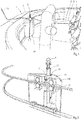
- Fig. 1 shows a part of an embodiment of a vessel according to the invention in the form of a tugboat 1.
- the tugboat 1 has a hull including a gunwale 2 and a deck 3.
- a towing winch 4 onto which a tow cable 5 is coiled is mounted on the deck 3.
- the tow cable 5 has a free end to which a hook member 6 is fixed, see Fig. 9 .
- Fig. 4 shows the hook member 6 as a separate part.
- the hook member 6 is provided with a first leg 7, a second leg 8 and a third leg 9, which legs 7-8 lie within a common main plane.
- the first leg 7 and the second leg 8 form a first V-shaped hook
- the first leg 7 and the third leg 9 form a second V-shaped hook.
- the hooks have respective hook bottoms 10, 11 where the first leg 7 meets the second leg 8 and the third leg 9, respectively.
- the second and third legs 8, 9 have respective free ends remote from the respective hook bottoms 10, 11. At the free ends of the second and third legs 8, 9 the hooks form respective openings 12, 13 between the first and second legs 7, 8 and between the first and third legs 7, 9.
- the openings 12, 13 are wide enough to receive a tow rope 14 that is launched from another vessel (not shown).
- the tow rope 14 is supported by the gunwale 2 and its free end to which a weight is attached, lies on the deck 3.
- the weight may be a separate weight, but it may also be integrated in the tow rope 14, for example by a plurality of knots of an end portion of the tow rope 14.
- the tow rope 14 can be received by one of the openings 12, 13 and clamped between the first and second legs 7, 8 or the first and third legs 7, 9.
- the first leg 7 of the hook member 6 has a through-hole 15 through which a shackle of the tow cable 5 passes, see Fig. 3 .
- the hook member 6 is made of a substantially rigid plastic.
- the hook member 6 may have elastic properties since it may be coiled on a winch on the vessel to be towed, together with the tow cable 5.
- the hook member 6 is preferably relatively small, for example it has a maximum length of 30 cm and a maximum width of 15 cm.
- the distance between the first leg 7 and the second leg 8 and the distance between the first leg 7 and the third leg 9 decreases substantially exponentially in a direction from the respective openings 12, 13 to the respective hook bottoms 10, 11.
- tow rope thicknesses can be received and clamped by the hook member 6. Furthermore, the thicknesses of the legs 7, 8, 9 decrease in a direction towards each other. This means that a flexible tow rope 14 will be deformed locally upon moving from one of the openings 12, 13 towards the corresponding hook bottom 10, 11, causing a proper attachment of the tow rope 14 to the hook member 6.
- the hook member 6 is linkable to a hook support 16 such that it is supported by the hook support 16.
- the hook support 16 comprises a carrier 27 which is movable on two parallel rails along the gunwale 2.
- the hook support as shown in the figures comprises an upwardly directed tube 17 in which a portion of the first leg 7 of the hook member 6 fits against an abutment.
- the tube 17 is mounted to the carrier 27 and moveable with respect thereto in longitudinal direction of the first leg 7.
- Figs. 1-3 show the hook member 6 in a rope receiving position with respect to the hook support 16. In this condition the hook member 6 is temporarily linked to the hook support 16 such that it has a fixed position with respect to the hook support 16.
- the fixed position is selected such that when moving the hook support 16 along the gunwale 2 the hook member 6 moves in a direction which has a component parallel to the main plane of the hook member 6. Consequently, the tube 17 and the tow rope 14 will meet each other as illustrated in Fig. 1 .
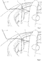
- the hook member 6 can be moved from the rope receiving position as shown in Fig. 1 downwardly to a rope clamping position in which the tow rope 14 is clamped in one of the two hooks of the hook member 6 by moving the tube 17 downwardly with respect to the carrier 27. At a certain moment during the movement of the hook member 6 and the tube 17 the tow rope 14 will extend in transverse direction of the main plane at one of the openings 12, 13 before it is clamped by the hook member 6.
- the hook support 16 and the first leg 7 of the hook member 6 form part of a rope positioning system for properly positioning the tow rope 14 and the hook member 6 with respect to each other.
- the hook member 6 is also movable with respect to the tube 17 in order to remove the hook member 6 from the tube 17, together with the tow rope 14 and the tow cable 5.
- Fig. 3 shows the tube 17 in a cut-away view.
- the tube 17 is provided with a T-shaped tow cable catcher 18 for guiding the tow cable 5 when the hook member 6 is located outside the tube 17. This situation happens when a towed vessel is decoupled from the tugboat 1 and the hook member 6 is thrown downwardly from the towed vessel and retrieved by the tugboat 1. Since the tow cable catcher 18 is movable in longitudinal direction of the tube 17 the tow cable catcher 18 can be positioned above the tube 17 and above an upper surface 19 of the carrier 27 which surrounds the tube 17. This is illustrated in Fig. 9 .
- the hook support 16 can be moved along the gunwale 2 until the tow cable catcher 18 contacts the tow cable 5, after which the tow cable catcher 18 can be lowered back into the tube 17 whereas the tow cable 5 is taken downwardly, as well. Subsequently, the tow cable catcher 18 can be held at a fixed position with respect to the tube 17 such that the tow cable catcher 18 becomes a guide for guiding the tow cable 5 when the towing winch 4 draws the tow cable 5 in order to bring the hook member 6 back into the rope receiving position as shown in Fig. 1 .
- the hook member 6 In the rope receiving position the hook member 6 is located above the tow cable catcher 18 and the tow cable 5 extends successively from the first leg 7 downwardly via the tow cable catcher 18 and upwardly therefrom to an upper end of the tube 17 and then to the towing winch 4, see Fig. 3 .
- the tube 17 and the first leg 7 are adapted such that the hook member 6 has two discrete positions with respect to the tube 17 in rotational direction about the first leg 7 in its rope receiving position. Hence, the upper end of the tube 17 is able to bring the hook member 6 in a predetermined orientation upon moving it into the tube 17.
- the tube 17 is displaceable in vertical direction with respect to the carrier 27 by a first hydraulic cylinder 25 between an upper position in which the hook member 6 is in the rope receiving position and the tube 17 projects upwardly from the upper surface 19 and a lower position in which the hook member 6 is in the rope clamping position and the upper end of the tube 17 is located below the upper surface 19. It is also conceivable that the upper end of the tube 17 is located at substantially the same level as the upper surface 19.
- the tow cable catcher 18 is displaceable with respect to the tube 17 in vertical direction of the tube 17 by a second hydraulic cylinder 26.
- the second hydraulic cylinder 26 In the situation as shown in Fig. 3 the second hydraulic cylinder 26 is in a retracted condition.
- the second hydraulic cylinder 26 may be operated such that the tow cable catcher 18 is moved upwardly with respect to the tube 17 and may project upwardly from the upper surface 19 whereas the upper end of the tube 17 remains at or below the upper surface 19.
- Fig. 4 shows that the first leg 7 of the hook member 6 is provided with flexible rods 20 extending in the main plane in outward direction from the first leg 7 as seen from the through-hole 15 towards the hook bottoms 10, 11.
- the flexible rods 20 have free ends which end at or close to the free ends of the second and third legs 8, 9 of the hook member 6 in a rest condition of the flexible rods 20.
- the flexible rods 20 can be moved towards the first leg 7 of the hook member 6 upon inserting the first leg 7 into the tube 17 such that they do not obstruct the openings 12, 13 in the rope receiving position of the hook member 6. This is illustrated in Fig. 12 .
- the flexible rods 20 return to their spread rest positions. When the hook member 6 is returned to the tugboat the risk of getting caught on any obstacle by the second and third legs 8, 9 is minimized due to the presence of the spread flexible rods 20.
- the hook member 6 In order to fix the tow rope 14 to the hook member 6 the hook member 6 has temporarily a fixed position with respect to the tube 17, after which the tube 17 including the hook member 6 is moved downwardly with respect to the upper surface 19 from the rope receiving position downwardly by the first hydraulic cylinder 25, but alternative driving mechanisms are conceivable.
- the upper surface 19 is provided with two slots 21 which extend at opposite sides of the tube 17 in the main plane of the hook member 6 when this is in the rope receiving position.
- the second and third legs 8, 9 of the hook member 6 fit in the respective slots 21.
- Fig. 7 shows a next step in which the tow rope 14 is pulled upwardly by the vessel to be towed such that the hook member 6 leaves the tube 17.
- the cable catcher 18 may then be moved upwardly simultaneously to a position above the upper surface 19 whereas the tube 17 is maintained at a fixed position with respect to the carrier 27.
- the cable catcher 18 may be lifted automatically up to a stop position by the pulling force of the tow cable 5 or driven upwardly by the second hydraulic cylinder 26.
- the tow cable 5 will leave the cable catcher 18 whereas the hook member 6 and the tow cable 5 will be drawn to the vessel to be towed.
- the latter condition is illustrated in Fig. 8 .
- the vessel which was towed will detach the tow cable 5 including the hook member 6 and launch it back to the tugboat 1.
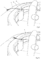
- the towing winch 4 will draw the tow cable 5 until it is located at the gunwale 2 as illustrated in Fig. 9 .
- the cable catcher 18 can be moved upwardly with respect to the tube 17 and the carrier 27 can be moved along the gunwale 2 until the cable catcher 18 contacts the tow cable 5.
- the T-shaped cable catcher 18 is moved downwardly with respect to the tube 17 as illustrated in Fig. 10 .
- the tow cable 5 is drawn further by the towing winch 4 until the first leg 7 of the hook member 6 enters the tube 17. This condition is shown in Fig. 11 .
- the hook member 6 the tube 17 and the cable catcher 18 can be moved upwardly together to the rope receiving condition of the hook member as shown in Fig. 5 .
- the upper end of the tube 17 and the hook member 6 are shaped such that the hook member 6 is forced in a predefined rotational position with respect to the tube 17 when entering the tube 17.
- Fig. 12 shows that in this embodiment the upper end of the tube 17 has two opposite recesses 22. At both sides of each recess the upper end of the tube 17 gradually increases to a top.
- the first leg 7 is provided with two pins 23 which project in opposite directions perpendicularly with respect to the main plane of the hook member 6. The distance between opposite ends of the pins 23 is larger than the internal diameter of the tube 17. Consequently, when the first leg 7 of the hook member 6 enters the tube 17 the upper end thereof will guide the hook member 6 to a position in which the pins 23 are received by the recesses 22.
- At least the recess 22 which is located closest to the towing winch 4 has such a shape that when the pins 23 are received by the recesses 22, as shown in Fig. 12 , there is still a trough-hole 24 between the pin 23 and the tube 17 in order to provide a passage for the tow cable 5, see Figs. 3 and 12 .
- the exterior side of the carrier 27 is provided with curved edges in order to facilitate guidance of the tow rope 14 and the tow cable 5 towards the hook member 6 and the cable catcher 18, respectively, upon moving the carrier 27 along the gunwale 2.
- hydraulic cylinders may be replaced by electrically operated cylinders or alternative driving means.
Landscapes
- Chemical & Material Sciences (AREA)
- Engineering & Computer Science (AREA)
- Combustion & Propulsion (AREA)
- Mechanical Engineering (AREA)
- Ocean & Marine Engineering (AREA)
- Load-Engaging Elements For Cranes (AREA)
- Catching Or Destruction (AREA)
Claims (15)
- Schiff (1) zum Schleppen eines anderen Schiffs, das aufweist: einen Rumpf, ein Schleppseil (5), das mit dem Rumpf gekoppelt ist, einen Haken (6) mit einem ersten Schenkel (7), der an einem freien Ende des Schleppseils (5) befestigt ist, einem zweiten Schenkel (8, 9) mit einem freien Ende und einem Hakenboden (10, 11), in dem der erste Schenkel (7) auf den zweiten Schenkel (8, 9) in einem Abstand vom freien Ende des zweiten Schenkels (8, 9) trifft, was eine Öffnung (12, 13) zwischen den Schenkeln (7-9) am freien Ende des zweiten Schenkels (8, 9) zum Aufnehmen einer Schlepptrosse (14) bildet, die am Schiff (1) liegt und von einem anderen Schiff abgegeben ist, wobei sich der erste und zweite Schenkel (7-9) in einer Hauptebene erstrecken, wobei das Schiff (1) ferner aufweist: eine Hakenhalterung (16), mit der der Haken verbindbar ist, ein Trossenpositioniersystem zum Positionieren einer Schlepptrosse (14) und der Hakenhalterung (16) im Hinblick aufeinander, so dass sich die Schlepptrosse (14) in Querrichtung der Hauptebene an der Öffnung (12, 13) des Hakens (6) erstreckt, wenn der Haken (6) mit der Hakenhalterung (16) verbunden ist, dadurch gekennzeichnet, dass der Haken ein V-förmiger Haken (6) ist, und wobei das Schiff (1) ein Trossenpresssystem zum Pressen einer an der Öffnung (12, 13) des Hakens (6) positionierten Schlepptrosse (14) zum Hakenboden (10, 11) aufweist, wenn der Haken (6) mit der Hakenhalterung (16) verbunden ist, was eine Klemmkraft zwischen den Schenkeln (7-9) und der Schlepptrosse (14) unter Betriebsbedingungen erzeugt.
- Schiff (1) nach Anspruch 1, wobei die Hakenhalterung (16) einen Träger (27) hat und wobei bei Verbindung des Hakens (6) mit der Hakenhalterung (16) der Haken (6) durch den Träger (27) über seinen ersten Schenkel (7) gestützt wird und im Hinblick auf die Hakenhalterung (16) in Längsrichtung des ersten Schenkels (7) zwischen einer Trossenaufnahmeposition zum Aufnehmen einer Schlepptrosse (14) an der Öffnung (12, 13) und einer Trossenklemmposition zum Klemmen einer Schlepptrosse (14) zwischen den Schenkeln (7-9) beweglich ist, wobei das Trossenpresssystem aufweist: ein Pressteil, das eine feste Position am Träger (27) hat, und einen Antriebsmechanismus zur Bewegung des Hakens (6) aus seiner Trossenaufnahmeposition in seine Trossenklemmposition, in deren Verlauf sich der Hakenboden (10, 11) zum Pressteil bewegt.
- Schiff (1) nach Anspruch 2, wobei das Trossenpositioniersystem durch den Träger (27) gebildet ist, der im Hinblick auf den Rumpf in einer Richtung parallel zur Hauptebene und quer zum ersten Schenkel (7) beweglich ist, wenn der Haken (6) mit der Hakenhalterung (16) verbunden ist.
- Schiff (1) nach Anspruch 2 oder 3, wobei das Pressteil neben dem Haken (6) an der Öffnung (12, 13) in Querrichtung der Hauptebene liegt, wenn der Haken (6) mit der Hakenhalterung (16) verbunden ist.
- Schiff (1) nach Anspruch 4, wobei das Pressteil an Gegenseiten des Hakens (6) an der Öffnung (12, 13) in Querrichtung der Hauptebene liegt, wenn der Haken (6) mit der Hakenhalterung (16) verbunden ist.
- Schiff (1) nach Anspruch 4 oder 5, wobei der Träger (27) eine Schlepptrossen-Aufnahmefläche (19) mit einem Schlitz (21) zum Aufnehmen mindestens eines Teils des zweiten Schenkels (8, 9) bei Bewegung des Hakens (6) aus seiner Trossenaufnahmeposition in seine Trossenklemmposition hat, wobei mindestens eine der Kanten des Schlitzes (21) das Pressteil bildet und wobei in der Trossenaufnahmeposition das freie Ende des zweiten Schenkels (8, 9) von der Schlepptrossen-Aufnahmefläche (19) entfernt ist.
- Schiff (1) nach Anspruch 6, wobei in der Trossenaufnahmeposition des Hakens (6) das freie Ende des zweiten Schenkels (8, 9) nach unten gerichtet ist.
- Schiff (1) nach Anspruch 6 oder 7, wobei die Hakenhalterung (16) mit einem Schleppseilfänger (18) zum Fangen und Führen des Schleppseils (5) versehen ist, wenn der Haken (6) einen Abstand von der Hakenhalterung (16) hat und durch das Schleppseil (5) zur Hakenhalterung (16) gezogen wird, wobei der Schleppseilfänger (18) am Träger (27) angebaut und im Hinblick darauf in gleicher Richtung wie der Haken (6) zwischen einer Fangposition, in der er von der Trossenaufnahmefläche (19) vorsteht, und einer Führungsposition beweglich ist, in der er jenseits des Hakens (6) bei Blick in Richtung entlang des ersten Schenkels vom Haken (6) zum Schleppseil (5) liegt, wenn sich der Haken (6) in seiner Trossenaufnahmeposition befindet, so dass sich in der Trossenaufnahmeposition das Schleppseil (5) nacheinander in einer Richtung vom ersten Schenkel (7) des Hakens (6) zum Schleppseilfänger (18) und über den Schleppseilfänger (18) in Gegenrichtung erstreckt.
- Schiff (1) nach Anspruch 8, wobei der Schleppseilfänger (18) ein T-förmiges Element aufweist.
- Schiff (1) nach Anspruch 8 oder 9, wobei die Hakenhalterung (16) mit einem Rohr (17) versehen ist, in dem sich ein Abschnitt des ersten Schenkels (7) an eine Anlage (22) anpasst und in das sich der Schleppseilfänger (18) einpasst, wobei der erste Schenkel (7) und der Schleppseilfänger (18) im Hinblick auf das Rohr (17) in Längsrichtung davon beweglich sind, wobei das Rohr (17) am Träger (27) angebaut und im Hinblick auf den Träger in einer Richtung parallel zum ersten Schenkel (7) beweglich ist, wobei das Rohr (17) im Hinblick auf den Träger (27) verriegelbar ist und der Schleppseilfänger (18) im Hinblick auf das Rohr (17) verriegelbar ist.
- Schiff (1) nach einem der vorstehenden Ansprüche und Anspruch 2, wobei die Hakenhalterung (16) und der erste Schenkel (7) so angepasst sind, dass der Haken (6) eine Endanzahl diskreter Positionen in Drehrichtung um den ersten Schenkel (7) in seiner Trossenaufnahmeposition hat.
- Schiff (1) nach Anspruch 11, wobei eines der Teile erster Schenkel (7) und Hakenhalterung (16) einen Vorsprung (23) hat und das andere der Teile erster Schenkel (7) und Hakenhalterung (16) eine Führungsfläche (22) zum Führen des Vorsprungs (23) beim Verbinden des ersten Schenkels (7) mit der Hakenhalterung (16) hat.
- Schiff (1) nach einem der vorstehenden Ansprüche, wobei der erste Schenkel (7) und/oder der zweite Schenkel (8, 9) eine abnehmende Dicke in Querrichtung der Hauptebene bei Blick in Richtung zueinander haben.
- Schiff (1) nach einem der vorstehenden Ansprüche, wobei der Abstand zwischen dem ersten Schenkel (7) und dem zweiten Schenkel (8, 9) in einer Richtung von der Öffnung (12, 13) zum Hakenboden (10, 11) zunehmend abnimmt.
- Schiff (1) nach einem der vorstehenden Ansprüche, wobei das Schleppseil (5) mit dem Rumpf über eine Schleppwinde (4) gekoppelt ist, wobei vorzugsweise mindestens ein Abschnitt des Schleppseils (5) elastisch ist.
Priority Applications (11)
| Application Number | Priority Date | Filing Date | Title |
|---|---|---|---|
| PL18156858T PL3527477T3 (pl) | 2018-02-15 | 2018-02-15 | Jednostka do holowania kolejnej jednostki |
| ES18156858T ES2893877T3 (es) | 2018-02-15 | 2018-02-15 | Una embarcación para remolcar otra embarcación |
| EP18156858.5A EP3527477B1 (de) | 2018-02-15 | 2018-02-15 | Schiff zum schleppen eines anderen schiffes |
| DK18156858.5T DK3527477T3 (da) | 2018-02-15 | 2018-02-15 | Fartøj til bugsering af et andet fartøj |
| PT181568585T PT3527477T (pt) | 2018-02-15 | 2018-02-15 | Embarcação para rebocar outra embarcação |
| US16/969,408 US11440624B2 (en) | 2018-02-15 | 2019-02-15 | Vessel for towing another vessel |
| PCT/EP2019/053837 WO2019158702A1 (en) | 2018-02-15 | 2019-02-15 | A vessel for towing another vessel |
| CN201980013056.1A CN111712430B (zh) | 2018-02-15 | 2019-02-15 | 用于拖曳另一艘船的船 |
| AU2019220437A AU2019220437B2 (en) | 2018-02-15 | 2019-02-15 | A vessel for towing another vessel |
| NZ766064A NZ766064A (en) | 2018-02-15 | 2019-02-15 | A vessel for towing another vessel |
| CA3088643A CA3088643A1 (en) | 2018-02-15 | 2019-02-15 | A vessel for towing another vessel |
Applications Claiming Priority (1)
| Application Number | Priority Date | Filing Date | Title |
|---|---|---|---|
| EP18156858.5A EP3527477B1 (de) | 2018-02-15 | 2018-02-15 | Schiff zum schleppen eines anderen schiffes |
Publications (2)
| Publication Number | Publication Date |
|---|---|
| EP3527477A1 EP3527477A1 (de) | 2019-08-21 |
| EP3527477B1 true EP3527477B1 (de) | 2021-07-21 |
Family
ID=61226443
Family Applications (1)
| Application Number | Title | Priority Date | Filing Date |
|---|---|---|---|
| EP18156858.5A Active EP3527477B1 (de) | 2018-02-15 | 2018-02-15 | Schiff zum schleppen eines anderen schiffes |
Country Status (11)
| Country | Link |
|---|---|
| US (1) | US11440624B2 (de) |
| EP (1) | EP3527477B1 (de) |
| CN (1) | CN111712430B (de) |
| AU (1) | AU2019220437B2 (de) |
| CA (1) | CA3088643A1 (de) |
| DK (1) | DK3527477T3 (de) |
| ES (1) | ES2893877T3 (de) |
| NZ (1) | NZ766064A (de) |
| PL (1) | PL3527477T3 (de) |
| PT (1) | PT3527477T (de) |
| WO (1) | WO2019158702A1 (de) |
Families Citing this family (4)
| Publication number | Priority date | Publication date | Assignee | Title |
|---|---|---|---|---|
| CN112455602B (zh) * | 2020-11-30 | 2022-02-15 | 上海海事大学 | 一种无人拖船用拖缆的自动连接装置的控制方法 |
| DE102021111952A1 (de) * | 2021-05-07 | 2022-11-10 | Macgregor Germany Gmbh & Co. Kg | System und Verfahren |
| CN118107726B (zh) * | 2024-04-30 | 2024-07-30 | 山东科技大学 | 一种海上拖曳平台 |
| CN119370282B (zh) * | 2024-12-04 | 2025-03-28 | 中交广州航道局有限公司 | 一种网箱拖航浮运装置及其拖航方法 |
Family Cites Families (10)
| Publication number | Priority date | Publication date | Assignee | Title |
|---|---|---|---|---|
| US86737A (en) * | 1869-02-09 | Improvement in propelling vessels ojst canals | ||
| US124326A (en) * | 1872-03-05 | Improvement in apparatus for towing canal-boats | ||
| CN2039661U (zh) * | 1988-11-10 | 1989-06-21 | 湖南省常德地区公路管理处 | 车辆渡船应急分离与自动挂脱钩装置 |
| CN2051213U (zh) * | 1989-05-02 | 1990-01-17 | 王德法 | 气控安全拖缆钩 |
| NL1010650C1 (nl) | 1998-11-25 | 2000-05-26 | Imc Group B V | Automatisch verbindingssysteem voor vaartuigen. |
| CN2395983Y (zh) * | 1999-09-23 | 2000-09-13 | 国家海洋局南海分局 | 打捞钩 |
| ES2245528B1 (es) | 2002-07-26 | 2007-03-16 | Sar Remolcadores, S.L | Sistema automatico de recogida y manipulacion de sirga para enganche entre remolcador y buque remolcado. |
| CN103832545A (zh) * | 2012-11-21 | 2014-06-04 | 青岛理工大学琴岛学院 | 新型港口轮船锁定装置 |
| CN103466060B (zh) * | 2013-09-06 | 2015-09-30 | 中国船舶重工集团公司第七○二研究所 | 自动脱缆可摆动式拖曳挂钩 |
| CN107336801B (zh) * | 2017-07-11 | 2019-04-09 | 苏州瀚隆石化装备有限公司 | 一种船舶停靠时拴缆绳用的缆钩锁紧释放装置 |
-
2018
- 2018-02-15 EP EP18156858.5A patent/EP3527477B1/de active Active
- 2018-02-15 DK DK18156858.5T patent/DK3527477T3/da active
- 2018-02-15 PT PT181568585T patent/PT3527477T/pt unknown
- 2018-02-15 ES ES18156858T patent/ES2893877T3/es active Active
- 2018-02-15 PL PL18156858T patent/PL3527477T3/pl unknown
-
2019
- 2019-02-15 US US16/969,408 patent/US11440624B2/en active Active
- 2019-02-15 WO PCT/EP2019/053837 patent/WO2019158702A1/en not_active Ceased
- 2019-02-15 AU AU2019220437A patent/AU2019220437B2/en active Active
- 2019-02-15 CA CA3088643A patent/CA3088643A1/en active Pending
- 2019-02-15 CN CN201980013056.1A patent/CN111712430B/zh active Active
- 2019-02-15 NZ NZ766064A patent/NZ766064A/en unknown
Also Published As
| Publication number | Publication date |
|---|---|
| PT3527477T (pt) | 2021-09-02 |
| EP3527477A1 (de) | 2019-08-21 |
| PL3527477T3 (pl) | 2022-01-10 |
| NZ766064A (en) | 2025-11-28 |
| CN111712430B (zh) | 2022-11-01 |
| AU2019220437B2 (en) | 2024-08-01 |
| CA3088643A1 (en) | 2019-08-22 |
| ES2893877T3 (es) | 2022-02-10 |
| CN111712430A (zh) | 2020-09-25 |
| AU2019220437A1 (en) | 2020-07-23 |
| WO2019158702A1 (en) | 2019-08-22 |
| US11440624B2 (en) | 2022-09-13 |
| DK3527477T3 (da) | 2021-09-20 |
| US20200398942A1 (en) | 2020-12-24 |
Similar Documents
| Publication | Publication Date | Title |
|---|---|---|
| AU2019220437B2 (en) | A vessel for towing another vessel | |
| CA2658981C (en) | An installation and a method for recovering a surface marine vehicle or an underwater vehicle | |
| CN112689595B (zh) | 具有链开关装置的链张紧器 | |
| EP2988991B1 (de) | Autonomes unterwasserfahrzeug und verfahren zum einholen eines solchen | |
| US8424847B2 (en) | Passive marine equipment recovery device | |
| US20090308299A1 (en) | Apparatus for recovering an underwater or marine vehicle | |
| US4067287A (en) | Anchor float adapter | |
| US20140212221A1 (en) | Method for connecting a flexible line to a structure of a fluid exploitation installation and associated connection device | |
| US8578872B1 (en) | Life vessel retrieval system | |
| US11772751B2 (en) | System for recovering a surface marine craft from a carrier ship | |
| US9944359B2 (en) | System comprising a dead weight and equipment on a trolling line having automated releases and retrievals and implementation method | |
| US7104213B2 (en) | Hawser guidance system for quick release mooring hooks | |
| CN117062749A (zh) | 具有用于夹持折叠绳的系留翼牵引系统 | |
| US5732647A (en) | Device and a method for tying and untying a tug line at a ship | |
| EP4086156B1 (de) | System zum aufbau und abbau einer leinenverbindung zwischen schiffen | |
| US20220371692A1 (en) | Cleat for mooring a watercraft, and mooring assembly having a cleat and a line having a stopper | |
| US20140314493A1 (en) | Method for installing a self-supporting tower for extracting hydrocarbons | |
| KR101179733B1 (ko) | 부유식 물체용 앵커 회수장치 | |
| KR102678353B1 (ko) | 스파 부이 진수 및 회수장치 | |
| DK180632B1 (en) | Mobile yarn and line setter | |
| CA2411141C (en) | Hawser guidance system for quick release mooring hooks | |
| HK40093052A (zh) | 具有用於夹持折叠绳的系留翼牵引系统 | |
| SU1504155A1 (ru) | Устройство дл соединени плавающего объекта с грузоподъемным механизмом | |
| GB2301074A (en) | Mooring apparatus | |
| GB2254533A (en) | Onboard handling of shellfish creels. |
Legal Events
| Date | Code | Title | Description |
|---|---|---|---|
| PUAI | Public reference made under article 153(3) epc to a published international application that has entered the european phase |
Free format text: ORIGINAL CODE: 0009012 |
|
| STAA | Information on the status of an ep patent application or granted ep patent |
Free format text: STATUS: THE APPLICATION HAS BEEN PUBLISHED |
|
| AK | Designated contracting states |
Kind code of ref document: A1 Designated state(s): AL AT BE BG CH CY CZ DE DK EE ES FI FR GB GR HR HU IE IS IT LI LT LU LV MC MK MT NL NO PL PT RO RS SE SI SK SM TR |
|
| AX | Request for extension of the european patent |
Extension state: BA ME |
|
| STAA | Information on the status of an ep patent application or granted ep patent |
Free format text: STATUS: REQUEST FOR EXAMINATION WAS MADE |
|
| 17P | Request for examination filed |
Effective date: 20200218 |
|
| RBV | Designated contracting states (corrected) |
Designated state(s): AL AT BE BG CH CY CZ DE DK EE ES FI FR GB GR HR HU IE IS IT LI LT LU LV MC MK MT NL NO PL PT RO RS SE SI SK SM TR |
|
| GRAP | Despatch of communication of intention to grant a patent |
Free format text: ORIGINAL CODE: EPIDOSNIGR1 |
|
| STAA | Information on the status of an ep patent application or granted ep patent |
Free format text: STATUS: GRANT OF PATENT IS INTENDED |
|
| INTG | Intention to grant announced |
Effective date: 20210323 |
|
| GRAS | Grant fee paid |
Free format text: ORIGINAL CODE: EPIDOSNIGR3 |
|
| GRAA | (expected) grant |
Free format text: ORIGINAL CODE: 0009210 |
|
| STAA | Information on the status of an ep patent application or granted ep patent |
Free format text: STATUS: THE PATENT HAS BEEN GRANTED |
|
| AK | Designated contracting states |
Kind code of ref document: B1 Designated state(s): AL AT BE BG CH CY CZ DE DK EE ES FI FR GB GR HR HU IE IS IT LI LT LU LV MC MK MT NL NO PL PT RO RS SE SI SK SM TR |
|
| REG | Reference to a national code |
Ref country code: GB Ref legal event code: FG4D |
|
| REG | Reference to a national code |
Ref country code: CH Ref legal event code: EP |
|
| REG | Reference to a national code |
Ref country code: DE Ref legal event code: R096 Ref document number: 602018020273 Country of ref document: DE |
|
| REG | Reference to a national code |
Ref country code: AT Ref legal event code: REF Ref document number: 1412384 Country of ref document: AT Kind code of ref document: T Effective date: 20210815 |
|
| REG | Reference to a national code |
Ref country code: IE Ref legal event code: FG4D |
|
| REG | Reference to a national code |
Ref country code: NL Ref legal event code: FP |
|
| REG | Reference to a national code |
Ref country code: PT Ref legal event code: SC4A Ref document number: 3527477 Country of ref document: PT Date of ref document: 20210902 Kind code of ref document: T Free format text: AVAILABILITY OF NATIONAL TRANSLATION Effective date: 20210826 |
|
| REG | Reference to a national code |
Ref country code: DK Ref legal event code: T3 Effective date: 20210916 |
|
| REG | Reference to a national code |
Ref country code: FI Ref legal event code: FGE |
|
| REG | Reference to a national code |
Ref country code: LT Ref legal event code: MG9D |
|
| REG | Reference to a national code |
Ref country code: NO Ref legal event code: T2 Effective date: 20210721 |
|
| REG | Reference to a national code |
Ref country code: AT Ref legal event code: MK05 Ref document number: 1412384 Country of ref document: AT Kind code of ref document: T Effective date: 20210721 |
|
| PG25 | Lapsed in a contracting state [announced via postgrant information from national office to epo] |
Ref country code: SE Free format text: LAPSE BECAUSE OF FAILURE TO SUBMIT A TRANSLATION OF THE DESCRIPTION OR TO PAY THE FEE WITHIN THE PRESCRIBED TIME-LIMIT Effective date: 20210721 Ref country code: RS Free format text: LAPSE BECAUSE OF FAILURE TO SUBMIT A TRANSLATION OF THE DESCRIPTION OR TO PAY THE FEE WITHIN THE PRESCRIBED TIME-LIMIT Effective date: 20210721 Ref country code: HR Free format text: LAPSE BECAUSE OF FAILURE TO SUBMIT A TRANSLATION OF THE DESCRIPTION OR TO PAY THE FEE WITHIN THE PRESCRIBED TIME-LIMIT Effective date: 20210721 Ref country code: AT Free format text: LAPSE BECAUSE OF FAILURE TO SUBMIT A TRANSLATION OF THE DESCRIPTION OR TO PAY THE FEE WITHIN THE PRESCRIBED TIME-LIMIT Effective date: 20210721 Ref country code: BG Free format text: LAPSE BECAUSE OF FAILURE TO SUBMIT A TRANSLATION OF THE DESCRIPTION OR TO PAY THE FEE WITHIN THE PRESCRIBED TIME-LIMIT Effective date: 20211021 Ref country code: LT Free format text: LAPSE BECAUSE OF FAILURE TO SUBMIT A TRANSLATION OF THE DESCRIPTION OR TO PAY THE FEE WITHIN THE PRESCRIBED TIME-LIMIT Effective date: 20210721 |
|
| REG | Reference to a national code |
Ref country code: ES Ref legal event code: FG2A Ref document number: 2893877 Country of ref document: ES Kind code of ref document: T3 Effective date: 20220210 |
|
| PG25 | Lapsed in a contracting state [announced via postgrant information from national office to epo] |
Ref country code: LV Free format text: LAPSE BECAUSE OF FAILURE TO SUBMIT A TRANSLATION OF THE DESCRIPTION OR TO PAY THE FEE WITHIN THE PRESCRIBED TIME-LIMIT Effective date: 20210721 Ref country code: GR Free format text: LAPSE BECAUSE OF FAILURE TO SUBMIT A TRANSLATION OF THE DESCRIPTION OR TO PAY THE FEE WITHIN THE PRESCRIBED TIME-LIMIT Effective date: 20211022 |
|
| REG | Reference to a national code |
Ref country code: DE Ref legal event code: R097 Ref document number: 602018020273 Country of ref document: DE |
|
| PLBE | No opposition filed within time limit |
Free format text: ORIGINAL CODE: 0009261 |
|
| STAA | Information on the status of an ep patent application or granted ep patent |
Free format text: STATUS: NO OPPOSITION FILED WITHIN TIME LIMIT |
|
| PG25 | Lapsed in a contracting state [announced via postgrant information from national office to epo] |
Ref country code: SM Free format text: LAPSE BECAUSE OF FAILURE TO SUBMIT A TRANSLATION OF THE DESCRIPTION OR TO PAY THE FEE WITHIN THE PRESCRIBED TIME-LIMIT Effective date: 20210721 Ref country code: SK Free format text: LAPSE BECAUSE OF FAILURE TO SUBMIT A TRANSLATION OF THE DESCRIPTION OR TO PAY THE FEE WITHIN THE PRESCRIBED TIME-LIMIT Effective date: 20210721 Ref country code: RO Free format text: LAPSE BECAUSE OF FAILURE TO SUBMIT A TRANSLATION OF THE DESCRIPTION OR TO PAY THE FEE WITHIN THE PRESCRIBED TIME-LIMIT Effective date: 20210721 Ref country code: EE Free format text: LAPSE BECAUSE OF FAILURE TO SUBMIT A TRANSLATION OF THE DESCRIPTION OR TO PAY THE FEE WITHIN THE PRESCRIBED TIME-LIMIT Effective date: 20210721 Ref country code: CZ Free format text: LAPSE BECAUSE OF FAILURE TO SUBMIT A TRANSLATION OF THE DESCRIPTION OR TO PAY THE FEE WITHIN THE PRESCRIBED TIME-LIMIT Effective date: 20210721 Ref country code: AL Free format text: LAPSE BECAUSE OF FAILURE TO SUBMIT A TRANSLATION OF THE DESCRIPTION OR TO PAY THE FEE WITHIN THE PRESCRIBED TIME-LIMIT Effective date: 20210721 |
|
| 26N | No opposition filed |
Effective date: 20220422 |
|
| PG25 | Lapsed in a contracting state [announced via postgrant information from national office to epo] |
Ref country code: MC Free format text: LAPSE BECAUSE OF FAILURE TO SUBMIT A TRANSLATION OF THE DESCRIPTION OR TO PAY THE FEE WITHIN THE PRESCRIBED TIME-LIMIT Effective date: 20210721 |
|
| REG | Reference to a national code |
Ref country code: CH Ref legal event code: PL |
|
| PG25 | Lapsed in a contracting state [announced via postgrant information from national office to epo] |
Ref country code: LU Free format text: LAPSE BECAUSE OF NON-PAYMENT OF DUE FEES Effective date: 20220215 |
|
| PG25 | Lapsed in a contracting state [announced via postgrant information from national office to epo] |
Ref country code: LI Free format text: LAPSE BECAUSE OF NON-PAYMENT OF DUE FEES Effective date: 20220228 Ref country code: IE Free format text: LAPSE BECAUSE OF NON-PAYMENT OF DUE FEES Effective date: 20220215 Ref country code: CH Free format text: LAPSE BECAUSE OF NON-PAYMENT OF DUE FEES Effective date: 20220228 |
|
| P01 | Opt-out of the competence of the unified patent court (upc) registered |
Effective date: 20230517 |
|
| PG25 | Lapsed in a contracting state [announced via postgrant information from national office to epo] |
Ref country code: MK Free format text: LAPSE BECAUSE OF FAILURE TO SUBMIT A TRANSLATION OF THE DESCRIPTION OR TO PAY THE FEE WITHIN THE PRESCRIBED TIME-LIMIT Effective date: 20210721 Ref country code: CY Free format text: LAPSE BECAUSE OF FAILURE TO SUBMIT A TRANSLATION OF THE DESCRIPTION OR TO PAY THE FEE WITHIN THE PRESCRIBED TIME-LIMIT Effective date: 20210721 |
|
| PG25 | Lapsed in a contracting state [announced via postgrant information from national office to epo] |
Ref country code: HU Free format text: LAPSE BECAUSE OF FAILURE TO SUBMIT A TRANSLATION OF THE DESCRIPTION OR TO PAY THE FEE WITHIN THE PRESCRIBED TIME-LIMIT; INVALID AB INITIO Effective date: 20180215 |
|
| PG25 | Lapsed in a contracting state [announced via postgrant information from national office to epo] |
Ref country code: MT Free format text: LAPSE BECAUSE OF FAILURE TO SUBMIT A TRANSLATION OF THE DESCRIPTION OR TO PAY THE FEE WITHIN THE PRESCRIBED TIME-LIMIT Effective date: 20210721 |
|
| REG | Reference to a national code |
Ref country code: NL Ref legal event code: RC Free format text: DETAILS LICENCE OR PLEDGE: RIGHT OF PLEDGE, ESTABLISHED Name of requester: ABN AMRO BANK N.V. Effective date: 20241231 |
|
| PGFP | Annual fee paid to national office [announced via postgrant information from national office to epo] |
Ref country code: DE Payment date: 20250227 Year of fee payment: 8 Ref country code: PT Payment date: 20250121 Year of fee payment: 8 |
|
| PGFP | Annual fee paid to national office [announced via postgrant information from national office to epo] |
Ref country code: DK Payment date: 20250225 Year of fee payment: 8 Ref country code: FI Payment date: 20250225 Year of fee payment: 8 |
|
| PGFP | Annual fee paid to national office [announced via postgrant information from national office to epo] |
Ref country code: ES Payment date: 20250303 Year of fee payment: 8 |
|
| PGFP | Annual fee paid to national office [announced via postgrant information from national office to epo] |
Ref country code: NO Payment date: 20250227 Year of fee payment: 8 |
|
| PGFP | Annual fee paid to national office [announced via postgrant information from national office to epo] |
Ref country code: BE Payment date: 20250227 Year of fee payment: 8 |
|
| PGFP | Annual fee paid to national office [announced via postgrant information from national office to epo] |
Ref country code: FR Payment date: 20250225 Year of fee payment: 8 Ref country code: PL Payment date: 20250122 Year of fee payment: 8 |
|
| PGFP | Annual fee paid to national office [announced via postgrant information from national office to epo] |
Ref country code: GB Payment date: 20250227 Year of fee payment: 8 Ref country code: IT Payment date: 20250220 Year of fee payment: 8 |
|
| PGFP | Annual fee paid to national office [announced via postgrant information from national office to epo] |
Ref country code: TR Payment date: 20250130 Year of fee payment: 8 |
|
| PGFP | Annual fee paid to national office [announced via postgrant information from national office to epo] |
Ref country code: NL Payment date: 20260226 Year of fee payment: 9 |