EP3527477B1 - A vessel for towing another vessel - Google Patents
A vessel for towing another vessel Download PDFInfo
- Publication number
- EP3527477B1 EP3527477B1 EP18156858.5A EP18156858A EP3527477B1 EP 3527477 B1 EP3527477 B1 EP 3527477B1 EP 18156858 A EP18156858 A EP 18156858A EP 3527477 B1 EP3527477 B1 EP 3527477B1
- Authority
- EP
- European Patent Office
- Prior art keywords
- hook
- leg
- rope
- vessel
- tow
- Prior art date
- Legal status (The legal status is an assumption and is not a legal conclusion. Google has not performed a legal analysis and makes no representation as to the accuracy of the status listed.)
- Active
Links
- 230000007423 decrease Effects 0.000 claims description 4
- 230000007246 mechanism Effects 0.000 claims description 3
- 230000003247 decreasing effect Effects 0.000 claims description 2
Images


Classifications
-
- B—PERFORMING OPERATIONS; TRANSPORTING
- B63—SHIPS OR OTHER WATERBORNE VESSELS; RELATED EQUIPMENT
- B63B—SHIPS OR OTHER WATERBORNE VESSELS; EQUIPMENT FOR SHIPPING
- B63B35/00—Vessels or similar floating structures specially adapted for specific purposes and not otherwise provided for
- B63B35/66—Tugs
- B63B35/68—Tugs for towing
-
- B—PERFORMING OPERATIONS; TRANSPORTING
- B63—SHIPS OR OTHER WATERBORNE VESSELS; RELATED EQUIPMENT
- B63B—SHIPS OR OTHER WATERBORNE VESSELS; EQUIPMENT FOR SHIPPING
- B63B21/00—Tying-up; Shifting, towing, or pushing equipment; Anchoring
- B63B21/56—Towing or pushing equipment
- B63B21/58—Adaptations of hooks for towing; Towing-hook mountings
Definitions
- the present invention relates to a vessel for towing another vessel.
- NL 1010650 is related to a vessel in the form of a tugboat which is provided with a hook that is fastened to one end of a tow cable. An opposite end of the tow cable is fixed to the tugboat. The tow cable passes through a guide block on the end of a boom. The hook is operated to catch a vertical tow rope which hangs from the bow of a ship to be towed. The tow rope has a buoy attached to its end. When the tow rope is pulled upwards, the hook and tow cable of the tugboat are pulled upwardly and can be attached to the ship to be towed.
- EP 1 535 831 is related to an automatic system for taking up a tow cable of a tugboat and fixing it to a tow rope of a vessel to be towed.
- the system is provided with a fastening carriage which moves on guides around the deck of the tugboat. Once the tow rope has been launched from the vessel to be towed to the tugboat, the carriage moves until a built-in sensor detects the presence of the tow rope at the level of the gunwale.
- the fastening carriage fixes the tow cable of the tugboat in a clamp, and once it is detected that the tow rope is introduced in the clamp it is closed and released from the carriage.
- An object of the invention is to provide a vessel which has a simple and robust system for fastening a tow cable of the vessel to a tow rope of a vessel to be towed.
- the vessel comprises a hull, a tow cable which is coupled to the hull, a V-shaped hook having a first leg which is fixed to a free end of the tow cable, a second leg including a free end and a hook bottom where the first leg meets the second leg at a distance from the free end of the second leg, hence forming an opening between the legs at the free end of the second leg for receiving a tow rope that is located at the vessel and launched from another vessel, wherein the first and second legs extend in a main plane, and wherein the vessel further comprises a hook support to which the hook is linkable, a rope positioning system for positioning a tow rope and the hook support with respect to each other such that the tow rope extends in transverse direction of the main plane at the opening of the hook when the hook is linked to the hook support, and a rope pressing system for pressing a tow rope positioned at the opening of the hook towards the hook bottom when the hook is linked to the hook support, hence creating a clamping
- the vessel may be a tugboat which receives a tow rope that is launched from a vessel to be towed.
- the rope positioning system is able to bring the tow rope and the hook in a mutual position such that the tow rope is located at the opening of the hook and the rope pressing system can press the rope between the legs of the hook. After pressing the tow rope between the legs, the tow rope is sufficiently fixed to the hook by the clamping force between the legs and the tow rope such that the hook can be released from the hook support without keeping a pressing force on the rope by the pressing system.
- the hook including the tow cable can be simply pulled upwardly by pulling the clamped tow rope by the vessel to be towed.
- the clamping force may be caused by elastic properties of at least one of the tow rope and the hook.
- the tow rope can be made of relatively thin braided rope which may be more flexible than the hook.
- the tow rope is only used for pulling the tow cable of the tugboat towards the vessel to be towed where the tow cable is fixed to a haul point, for example, such that the tow rope itself is not used during towing.
- tow cable may be coupled to the hull through a winch.
- the hook support has a carrier, wherein when the hook is linked to the hook support the hook is supported by the hook support via its first leg and moveable with respect to the carrier in longitudinal direction of the first leg between a rope receiving position for receiving a tow rope at the opening and a rope clamping position for clamping a tow rope between the legs, wherein the rope pressing system comprises a pressing member which has a fixed position at the carrier and a driving mechanism for moving the hook from its rope receiving position to its rope clamping position during which the hook bottom moves towards the pressing member.
- the pressing member may stay at the vessel when the hook including the tow cable are pulled upwardly by the vessel to be towed.
- the rope positioning system is formed by the carrier which is movable with respect to the hull in a direction parallel to the main plane and transversely to the first leg when the hook is linked to the hook support. This provides the opportunity to move the hook support with respect to the hull until the hook contacts the tow rope and the tow rope tends to bend about the first leg of the hook. In this condition the tow rope may automatically extend in transverse direction of the main plane of the hook at the opening of the hook.
- the pressing member may be located next to the hook at the opening in transverse direction of the main plane when the hook is linked to the hook support. In this case the pressing member pulls the tow rope between the legs of the hook.
- the pressing member may be located at opposite sides of the hook at the opening in transverse direction of the main plane when the hook is linked to the hook support.
- the carrier has a tow rope receiving surface including a slot for receiving at least a part of the second leg upon moving the hook from its rope receiving position to its rope clamping position, wherein at least one of the edges of the slot forms the pressing member, and wherein in the rope receiving position the free end of the second leg is remote from the tow rope receiving surface.
- the free end of the second leg may be directed downwardly when the hook is in the rope receiving position. This means that the hook is moved downwardly from the rope receiving position to the rope clamping position in which the tow rope is clamped between the legs of the hook.
- the tow rope receiving surface may be a horizontal upper surface of the carrier.
- the hook support is provided with a tow cable catcher for catching and guiding the tow cable when the hook is at a distance from the hook support and drawn by the tow cable towards the hook support, which tow cable catcher is mounted to the carrier and movable with respect thereto in the same direction as the hook between a catching position in which it projects from the rope receiving surface and a guiding position in which it is located beyond the hook as seen in a direction along the first leg from the hook to the tow cable when the hook is in its rope receiving position, such that in the rope receiving position the tow cable extends successively in one direction from the first leg of the hook to the tow cable catcher and via the tow cable catcher in opposite direction.
- the tow cable catcher may comprise a T-shaped element.
- each of the lateral parts of the T-shaped element can be used for guiding the tow cable when the cable catcher guides the tow cable as described above.
- each of the lateral parts can function as a catching hook when the T-shaped element projects from the tow rope receiving surface.
- the catching hook can be moved with respect to the hull by moving the carrier. This provides the opportunity of contacting and catching the tow cable when this is launched from the towed vessel after a towing operation.
- the tow cable catcher can also be moved with respect to the carrier to its guiding position whereas the tow cable can be drawn, for example by a towing winch, in order to pull the hook towards the hook support.
- the hook suppport is provided with a tube in which a portion of the first leg fits against an abutment and in which the tow cable catcher fits, wherein the first leg and the tow cable catcher are movable with respect to the tube in longitudinal direction thereof, wherein the tube is mounted to the carrier and movable with respect to the carrier in a direction parallel to the first leg, wherein the tube is lockable with respect to the carrier and the tow cable catcher is lockable with respect to the tube.
- the free end of the second leg may lie at a distance from the tube as seen along the tube.
- the tube and the hook When the hook must be moved from its rope receiving position towards its rope clamping position the tube and the hook must be moved together with respect to the carrier during which the tow cable catcher may be locked with respect to the tube.
- the hook When the hook is moved in opposite direction from its rope clamping position the tube can be locked with respect to the carrier and the tow cable catcher can be de-locked with respect to the tube such that upon pulling the clamped tow rope the hook moves out of the tube and may take the tow cable catcher to a position where the T-shaped element projects from the tow rope receiving surface of the carrier such that the tow cable can be released from the cable catcher.
- the tow cable including the hook is dropped by the towed vessel and can be drawn back.
- the T-shaped element can be positioned in its catching position and the tube can be positioned to a location in which the T-shaped element also projects from the tube.
- the T-shaped element can be moved into the tube. It can be locked with respect to the tube in its guiding position and the hook can be moved towards the tube by drawing the tow cable, for example by a towing winch.
- the T-shaped element guides the tow cable.
- the lateral parts of the T-shaped element preferably fit inside the tube such that the tow cable cannot escape between the lateral parts and the tube when the T-shaped element is in its guiding position.
- the hook support and the first leg may be adapted such that the hook has a final number of discrete positions in rotational direction about the first leg in its rope receiving position. This provides one or more predefined orientations of the hook with respect to the hook support.
- one of the first leg and the hook support has a protrusion and the other one of the first leg and the hook support has a guiding surface for guiding the protrusion upon linking the first leg to the hook support.
- At least one of the first leg and the second leg may have a decreasing thickness in transverse direction of the main plane as seen in a direction towards each other. This provides an appropriate clamping force on a tow rope.
- the distance between the first leg and the second leg may decrease progressively in a direction from the opening to the hook bottom, for example substantially exponentially, which results in reliable clamping performance of the tow rope.
- At least a portion of the tow cable may be resilient, for example a portion at or close to the hook.
- Such a resilient portion of the tow cable may have a lower elastic modulus than the remainder of the tow cable. This avoids excessive forces between the hook member and the hook support upon linking the hook to the hook support. This might typically occur in case the tow cable is drawn by a heavy-duty towing winch which may not stop immediately upon switching it off.
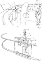
- Fig. 1 shows a part of an embodiment of a vessel according to the invention in the form of a tugboat 1.
- the tugboat 1 has a hull including a gunwale 2 and a deck 3.
- a towing winch 4 onto which a tow cable 5 is coiled is mounted on the deck 3.
- the tow cable 5 has a free end to which a hook member 6 is fixed, see Fig. 9 .
- Fig. 4 shows the hook member 6 as a separate part.
- the hook member 6 is provided with a first leg 7, a second leg 8 and a third leg 9, which legs 7-8 lie within a common main plane.
- the first leg 7 and the second leg 8 form a first V-shaped hook
- the first leg 7 and the third leg 9 form a second V-shaped hook.
- the hooks have respective hook bottoms 10, 11 where the first leg 7 meets the second leg 8 and the third leg 9, respectively.
- the second and third legs 8, 9 have respective free ends remote from the respective hook bottoms 10, 11. At the free ends of the second and third legs 8, 9 the hooks form respective openings 12, 13 between the first and second legs 7, 8 and between the first and third legs 7, 9.
- the openings 12, 13 are wide enough to receive a tow rope 14 that is launched from another vessel (not shown).
- the tow rope 14 is supported by the gunwale 2 and its free end to which a weight is attached, lies on the deck 3.
- the weight may be a separate weight, but it may also be integrated in the tow rope 14, for example by a plurality of knots of an end portion of the tow rope 14.
- the tow rope 14 can be received by one of the openings 12, 13 and clamped between the first and second legs 7, 8 or the first and third legs 7, 9.
- the first leg 7 of the hook member 6 has a through-hole 15 through which a shackle of the tow cable 5 passes, see Fig. 3 .
- the hook member 6 is made of a substantially rigid plastic.
- the hook member 6 may have elastic properties since it may be coiled on a winch on the vessel to be towed, together with the tow cable 5.
- the hook member 6 is preferably relatively small, for example it has a maximum length of 30 cm and a maximum width of 15 cm.
- the distance between the first leg 7 and the second leg 8 and the distance between the first leg 7 and the third leg 9 decreases substantially exponentially in a direction from the respective openings 12, 13 to the respective hook bottoms 10, 11.
- tow rope thicknesses can be received and clamped by the hook member 6. Furthermore, the thicknesses of the legs 7, 8, 9 decrease in a direction towards each other. This means that a flexible tow rope 14 will be deformed locally upon moving from one of the openings 12, 13 towards the corresponding hook bottom 10, 11, causing a proper attachment of the tow rope 14 to the hook member 6.
- the hook member 6 is linkable to a hook support 16 such that it is supported by the hook support 16.
- the hook support 16 comprises a carrier 27 which is movable on two parallel rails along the gunwale 2.
- the hook support as shown in the figures comprises an upwardly directed tube 17 in which a portion of the first leg 7 of the hook member 6 fits against an abutment.
- the tube 17 is mounted to the carrier 27 and moveable with respect thereto in longitudinal direction of the first leg 7.
- Figs. 1-3 show the hook member 6 in a rope receiving position with respect to the hook support 16. In this condition the hook member 6 is temporarily linked to the hook support 16 such that it has a fixed position with respect to the hook support 16.
- the fixed position is selected such that when moving the hook support 16 along the gunwale 2 the hook member 6 moves in a direction which has a component parallel to the main plane of the hook member 6. Consequently, the tube 17 and the tow rope 14 will meet each other as illustrated in Fig. 1 .
- the hook member 6 can be moved from the rope receiving position as shown in Fig. 1 downwardly to a rope clamping position in which the tow rope 14 is clamped in one of the two hooks of the hook member 6 by moving the tube 17 downwardly with respect to the carrier 27. At a certain moment during the movement of the hook member 6 and the tube 17 the tow rope 14 will extend in transverse direction of the main plane at one of the openings 12, 13 before it is clamped by the hook member 6.
- the hook support 16 and the first leg 7 of the hook member 6 form part of a rope positioning system for properly positioning the tow rope 14 and the hook member 6 with respect to each other.
- the hook member 6 is also movable with respect to the tube 17 in order to remove the hook member 6 from the tube 17, together with the tow rope 14 and the tow cable 5.
- Fig. 3 shows the tube 17 in a cut-away view.
- the tube 17 is provided with a T-shaped tow cable catcher 18 for guiding the tow cable 5 when the hook member 6 is located outside the tube 17. This situation happens when a towed vessel is decoupled from the tugboat 1 and the hook member 6 is thrown downwardly from the towed vessel and retrieved by the tugboat 1. Since the tow cable catcher 18 is movable in longitudinal direction of the tube 17 the tow cable catcher 18 can be positioned above the tube 17 and above an upper surface 19 of the carrier 27 which surrounds the tube 17. This is illustrated in Fig. 9 .
- the hook support 16 can be moved along the gunwale 2 until the tow cable catcher 18 contacts the tow cable 5, after which the tow cable catcher 18 can be lowered back into the tube 17 whereas the tow cable 5 is taken downwardly, as well. Subsequently, the tow cable catcher 18 can be held at a fixed position with respect to the tube 17 such that the tow cable catcher 18 becomes a guide for guiding the tow cable 5 when the towing winch 4 draws the tow cable 5 in order to bring the hook member 6 back into the rope receiving position as shown in Fig. 1 .
- the hook member 6 In the rope receiving position the hook member 6 is located above the tow cable catcher 18 and the tow cable 5 extends successively from the first leg 7 downwardly via the tow cable catcher 18 and upwardly therefrom to an upper end of the tube 17 and then to the towing winch 4, see Fig. 3 .
- the tube 17 and the first leg 7 are adapted such that the hook member 6 has two discrete positions with respect to the tube 17 in rotational direction about the first leg 7 in its rope receiving position. Hence, the upper end of the tube 17 is able to bring the hook member 6 in a predetermined orientation upon moving it into the tube 17.
- the tube 17 is displaceable in vertical direction with respect to the carrier 27 by a first hydraulic cylinder 25 between an upper position in which the hook member 6 is in the rope receiving position and the tube 17 projects upwardly from the upper surface 19 and a lower position in which the hook member 6 is in the rope clamping position and the upper end of the tube 17 is located below the upper surface 19. It is also conceivable that the upper end of the tube 17 is located at substantially the same level as the upper surface 19.
- the tow cable catcher 18 is displaceable with respect to the tube 17 in vertical direction of the tube 17 by a second hydraulic cylinder 26.
- the second hydraulic cylinder 26 In the situation as shown in Fig. 3 the second hydraulic cylinder 26 is in a retracted condition.
- the second hydraulic cylinder 26 may be operated such that the tow cable catcher 18 is moved upwardly with respect to the tube 17 and may project upwardly from the upper surface 19 whereas the upper end of the tube 17 remains at or below the upper surface 19.
- Fig. 4 shows that the first leg 7 of the hook member 6 is provided with flexible rods 20 extending in the main plane in outward direction from the first leg 7 as seen from the through-hole 15 towards the hook bottoms 10, 11.
- the flexible rods 20 have free ends which end at or close to the free ends of the second and third legs 8, 9 of the hook member 6 in a rest condition of the flexible rods 20.
- the flexible rods 20 can be moved towards the first leg 7 of the hook member 6 upon inserting the first leg 7 into the tube 17 such that they do not obstruct the openings 12, 13 in the rope receiving position of the hook member 6. This is illustrated in Fig. 12 .
- the flexible rods 20 return to their spread rest positions. When the hook member 6 is returned to the tugboat the risk of getting caught on any obstacle by the second and third legs 8, 9 is minimized due to the presence of the spread flexible rods 20.
- the hook member 6 In order to fix the tow rope 14 to the hook member 6 the hook member 6 has temporarily a fixed position with respect to the tube 17, after which the tube 17 including the hook member 6 is moved downwardly with respect to the upper surface 19 from the rope receiving position downwardly by the first hydraulic cylinder 25, but alternative driving mechanisms are conceivable.
- the upper surface 19 is provided with two slots 21 which extend at opposite sides of the tube 17 in the main plane of the hook member 6 when this is in the rope receiving position.
- the second and third legs 8, 9 of the hook member 6 fit in the respective slots 21.
- Fig. 7 shows a next step in which the tow rope 14 is pulled upwardly by the vessel to be towed such that the hook member 6 leaves the tube 17.
- the cable catcher 18 may then be moved upwardly simultaneously to a position above the upper surface 19 whereas the tube 17 is maintained at a fixed position with respect to the carrier 27.
- the cable catcher 18 may be lifted automatically up to a stop position by the pulling force of the tow cable 5 or driven upwardly by the second hydraulic cylinder 26.
- the tow cable 5 will leave the cable catcher 18 whereas the hook member 6 and the tow cable 5 will be drawn to the vessel to be towed.
- the latter condition is illustrated in Fig. 8 .
- the vessel which was towed will detach the tow cable 5 including the hook member 6 and launch it back to the tugboat 1.
- the towing winch 4 will draw the tow cable 5 until it is located at the gunwale 2 as illustrated in Fig. 9 .
- the cable catcher 18 can be moved upwardly with respect to the tube 17 and the carrier 27 can be moved along the gunwale 2 until the cable catcher 18 contacts the tow cable 5.
- the T-shaped cable catcher 18 is moved downwardly with respect to the tube 17 as illustrated in Fig. 10 .
- the tow cable 5 is drawn further by the towing winch 4 until the first leg 7 of the hook member 6 enters the tube 17. This condition is shown in Fig. 11 .
- the hook member 6 the tube 17 and the cable catcher 18 can be moved upwardly together to the rope receiving condition of the hook member as shown in Fig. 5 .
- the upper end of the tube 17 and the hook member 6 are shaped such that the hook member 6 is forced in a predefined rotational position with respect to the tube 17 when entering the tube 17.
- Fig. 12 shows that in this embodiment the upper end of the tube 17 has two opposite recesses 22. At both sides of each recess the upper end of the tube 17 gradually increases to a top.
- the first leg 7 is provided with two pins 23 which project in opposite directions perpendicularly with respect to the main plane of the hook member 6. The distance between opposite ends of the pins 23 is larger than the internal diameter of the tube 17. Consequently, when the first leg 7 of the hook member 6 enters the tube 17 the upper end thereof will guide the hook member 6 to a position in which the pins 23 are received by the recesses 22.
- At least the recess 22 which is located closest to the towing winch 4 has such a shape that when the pins 23 are received by the recesses 22, as shown in Fig. 12 , there is still a trough-hole 24 between the pin 23 and the tube 17 in order to provide a passage for the tow cable 5, see Figs. 3 and 12 .
- the exterior side of the carrier 27 is provided with curved edges in order to facilitate guidance of the tow rope 14 and the tow cable 5 towards the hook member 6 and the cable catcher 18, respectively, upon moving the carrier 27 along the gunwale 2.
- hydraulic cylinders may be replaced by electrically operated cylinders or alternative driving means.
Description
- The present invention relates to a vessel for towing another vessel.
-
NL 1010650 -
EP 1 535 831 - An object of the invention is to provide a vessel which has a simple and robust system for fastening a tow cable of the vessel to a tow rope of a vessel to be towed.
- This object is accomplished with the vessel according to the invention, which vessel comprises a hull, a tow cable which is coupled to the hull, a V-shaped hook having a first leg which is fixed to a free end of the tow cable, a second leg including a free end and a hook bottom where the first leg meets the second leg at a distance from the free end of the second leg, hence forming an opening between the legs at the free end of the second leg for receiving a tow rope that is located at the vessel and launched from another vessel, wherein the first and second legs extend in a main plane, and wherein the vessel further comprises a hook support to which the hook is linkable, a rope positioning system for positioning a tow rope and the hook support with respect to each other such that the tow rope extends in transverse direction of the main plane at the opening of the hook when the hook is linked to the hook support, and a rope pressing system for pressing a tow rope positioned at the opening of the hook towards the hook bottom when the hook is linked to the hook support, hence creating a clamping force between the legs and the tow rope under operating conditions.
- The vessel may be a tugboat which receives a tow rope that is launched from a vessel to be towed. The rope positioning system is able to bring the tow rope and the hook in a mutual position such that the tow rope is located at the opening of the hook and the rope pressing system can press the rope between the legs of the hook. After pressing the tow rope between the legs, the tow rope is sufficiently fixed to the hook by the clamping force between the legs and the tow rope such that the hook can be released from the hook support without keeping a pressing force on the rope by the pressing system. The hook including the tow cable can be simply pulled upwardly by pulling the clamped tow rope by the vessel to be towed.
- The clamping force may be caused by elastic properties of at least one of the tow rope and the hook. In practice the tow rope can be made of relatively thin braided rope which may be more flexible than the hook. Usually, the tow rope is only used for pulling the tow cable of the tugboat towards the vessel to be towed where the tow cable is fixed to a haul point, for example, such that the tow rope itself is not used during towing.
- It is noted that the tow cable may be coupled to the hull through a winch.
- In a particular embodiment, the hook support has a carrier, wherein when the hook is linked to the hook support the hook is supported by the hook support via its first leg and moveable with respect to the carrier in longitudinal direction of the first leg between a rope receiving position for receiving a tow rope at the opening and a rope clamping position for clamping a tow rope between the legs, wherein the rope pressing system comprises a pressing member which has a fixed position at the carrier and a driving mechanism for moving the hook from its rope receiving position to its rope clamping position during which the hook bottom moves towards the pressing member. This means that the pressing member may stay at the vessel when the hook including the tow cable are pulled upwardly by the vessel to be towed.
- In a more particular embodiment the rope positioning system is formed by the carrier which is movable with respect to the hull in a direction parallel to the main plane and transversely to the first leg when the hook is linked to the hook support. This provides the opportunity to move the hook support with respect to the hull until the hook contacts the tow rope and the tow rope tends to bend about the first leg of the hook. In this condition the tow rope may automatically extend in transverse direction of the main plane of the hook at the opening of the hook.
- The pressing member may be located next to the hook at the opening in transverse direction of the main plane when the hook is linked to the hook support. In this case the pressing member pulls the tow rope between the legs of the hook.
- In order to create a pulling force at both sides of the main plane the pressing member may be located at opposite sides of the hook at the opening in transverse direction of the main plane when the hook is linked to the hook support.
- In a practical embodiment the carrier has a tow rope receiving surface including a slot for receiving at least a part of the second leg upon moving the hook from its rope receiving position to its rope clamping position, wherein at least one of the edges of the slot forms the pressing member, and wherein in the rope receiving position the free end of the second leg is remote from the tow rope receiving surface. Before a clamping action is started a tow rope of a vessel to be towed can be positioned on the tow rope receiving surface such that the tow rope extends transversely to the slot on the slot. In this case the edges of the slot create a pulling force on the tow rope when moving the second leg into the slot. In the rope receiving position the tow rope can slide between the free end of the second leg and the tow rope receiving surface to the opening of the hook.
- The free end of the second leg may be directed downwardly when the hook is in the rope receiving position. This means that the hook is moved downwardly from the rope receiving position to the rope clamping position in which the tow rope is clamped between the legs of the hook. The tow rope receiving surface may be a horizontal upper surface of the carrier.
- In an advantageous embodiment the hook support is provided with a tow cable catcher for catching and guiding the tow cable when the hook is at a distance from the hook support and drawn by the tow cable towards the hook support, which tow cable catcher is mounted to the carrier and movable with respect thereto in the same direction as the hook between a catching position in which it projects from the rope receiving surface and a guiding position in which it is located beyond the hook as seen in a direction along the first leg from the hook to the tow cable when the hook is in its rope receiving position, such that in the rope receiving position the tow cable extends successively in one direction from the first leg of the hook to the tow cable catcher and via the tow cable catcher in opposite direction.
- The tow cable catcher may comprise a T-shaped element. On the one hand, each of the lateral parts of the T-shaped element can be used for guiding the tow cable when the cable catcher guides the tow cable as described above. On the other hand, each of the lateral parts can function as a catching hook when the T-shaped element projects from the tow rope receiving surface. The catching hook can be moved with respect to the hull by moving the carrier. This provides the opportunity of contacting and catching the tow cable when this is launched from the towed vessel after a towing operation. After catching the tow cable the tow cable catcher can also be moved with respect to the carrier to its guiding position whereas the tow cable can be drawn, for example by a towing winch, in order to pull the hook towards the hook support.
- In a practical embodiment the hook suppport is provided with a tube in which a portion of the first leg fits against an abutment and in which the tow cable catcher fits, wherein the first leg and the tow cable catcher are movable with respect to the tube in longitudinal direction thereof, wherein the tube is mounted to the carrier and movable with respect to the carrier in a direction parallel to the first leg, wherein the tube is lockable with respect to the carrier and the tow cable catcher is lockable with respect to the tube. In the rope receiving position the free end of the second leg may lie at a distance from the tube as seen along the tube. When the hook must be moved from its rope receiving position towards its rope clamping position the tube and the hook must be moved together with respect to the carrier during which the tow cable catcher may be locked with respect to the tube. When the hook is moved in opposite direction from its rope clamping position the tube can be locked with respect to the carrier and the tow cable catcher can be de-locked with respect to the tube such that upon pulling the clamped tow rope the hook moves out of the tube and may take the tow cable catcher to a position where the T-shaped element projects from the tow rope receiving surface of the carrier such that the tow cable can be released from the cable catcher.
- After finalizing a towing operation the tow cable including the hook is dropped by the towed vessel and can be drawn back. The T-shaped element can be positioned in its catching position and the tube can be positioned to a location in which the T-shaped element also projects from the tube. When the tube is locked in this position and the T-shaped element catches the tow cable the T-shaped element can be moved into the tube. It can be locked with respect to the tube in its guiding position and the hook can be moved towards the tube by drawing the tow cable, for example by a towing winch. During the latter operation the T-shaped element guides the tow cable.
- The lateral parts of the T-shaped element preferably fit inside the tube such that the tow cable cannot escape between the lateral parts and the tube when the T-shaped element is in its guiding position.
- The hook support and the first leg may be adapted such that the hook has a final number of discrete positions in rotational direction about the first leg in its rope receiving position. This provides one or more predefined orientations of the hook with respect to the hook support.
- In a specific embodiment one of the first leg and the hook support has a protrusion and the other one of the first leg and the hook support has a guiding surface for guiding the protrusion upon linking the first leg to the hook support. This is a simple structure for bringing the hook in a desired orientation with respect to the hook support.
- At least one of the first leg and the second leg may have a decreasing thickness in transverse direction of the main plane as seen in a direction towards each other. This provides an appropriate clamping force on a tow rope.
- The distance between the first leg and the second leg may decrease progressively in a direction from the opening to the hook bottom, for example substantially exponentially, which results in reliable clamping performance of the tow rope.
- At least a portion of the tow cable may be resilient, for example a portion at or close to the hook. Such a resilient portion of the tow cable may have a lower elastic modulus than the remainder of the tow cable. This avoids excessive forces between the hook member and the hook support upon linking the hook to the hook support. This might typically occur in case the tow cable is drawn by a heavy-duty towing winch which may not stop immediately upon switching it off.
- The invention will hereafter be elucidated with reference to very schematic drawings showing an embodiment of the invention by way of example.
-
Fig. 1 is a perspective view of a part of an embodiment of a vessel according to the invention. -
Fig. 2 is a perspective view of a part of the vessel ofFig. 1 on a larger scale. -
Fig. 3 is a perspective cut-away view of the part ofFig. 2 as seen from a different side. -
Fig. 4 is a perspective view of a part of the vessel ofFig. 1 on a larger scale, showing a hook member. -
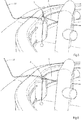
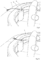
Figs. 5-11 are similar views asFig. 1 , showing successive steps of fastening a tow cable and a tow rope to each other. -
Fig. 12 is a similar view asFig. 2 , showing a part thereof on a large scale. -
Fig. 1 shows a part of an embodiment of a vessel according to the invention in the form of atugboat 1. Thetugboat 1 has a hull including agunwale 2 and adeck 3. A towingwinch 4 onto which atow cable 5 is coiled is mounted on thedeck 3. Thetow cable 5 has a free end to which ahook member 6 is fixed, seeFig. 9 . -
Fig. 4 shows thehook member 6 as a separate part. Thehook member 6 is provided with afirst leg 7, asecond leg 8 and athird leg 9, which legs 7-8 lie within a common main plane. Thefirst leg 7 and thesecond leg 8 form a first V-shaped hook, whereas thefirst leg 7 and thethird leg 9 form a second V-shaped hook. The hooks haverespective hook bottoms first leg 7 meets thesecond leg 8 and thethird leg 9, respectively. The second andthird legs respective hook bottoms third legs respective openings second legs third legs openings tow rope 14 that is launched from another vessel (not shown). In the situation as shown inFig. 1 thetow rope 14 is supported by thegunwale 2 and its free end to which a weight is attached, lies on thedeck 3. The weight may be a separate weight, but it may also be integrated in thetow rope 14, for example by a plurality of knots of an end portion of thetow rope 14. Thetow rope 14 can be received by one of theopenings second legs third legs - The
first leg 7 of thehook member 6 has a through-hole 15 through which a shackle of thetow cable 5 passes, seeFig. 3 . In the embodiment as shown inFig. 4 thehook member 6 is made of a substantially rigid plastic. Thehook member 6 may have elastic properties since it may be coiled on a winch on the vessel to be towed, together with thetow cable 5. For similar reasons thehook member 6 is preferably relatively small, for example it has a maximum length of 30 cm and a maximum width of 15 cm. The distance between thefirst leg 7 and thesecond leg 8 and the distance between thefirst leg 7 and thethird leg 9 decreases substantially exponentially in a direction from therespective openings respective hook bottoms hook member 6. Furthermore, the thicknesses of thelegs flexible tow rope 14 will be deformed locally upon moving from one of theopenings tow rope 14 to thehook member 6. - The
hook member 6 is linkable to ahook support 16 such that it is supported by thehook support 16. Thehook support 16 comprises acarrier 27 which is movable on two parallel rails along thegunwale 2. The hook support as shown in the figures comprises an upwardly directedtube 17 in which a portion of thefirst leg 7 of thehook member 6 fits against an abutment. Thetube 17 is mounted to thecarrier 27 and moveable with respect thereto in longitudinal direction of thefirst leg 7.Figs. 1-3 show thehook member 6 in a rope receiving position with respect to thehook support 16. In this condition thehook member 6 is temporarily linked to thehook support 16 such that it has a fixed position with respect to thehook support 16. The fixed position is selected such that when moving thehook support 16 along thegunwale 2 thehook member 6 moves in a direction which has a component parallel to the main plane of thehook member 6. Consequently, thetube 17 and thetow rope 14 will meet each other as illustrated inFig. 1 . Thehook member 6 can be moved from the rope receiving position as shown inFig. 1 downwardly to a rope clamping position in which thetow rope 14 is clamped in one of the two hooks of thehook member 6 by moving thetube 17 downwardly with respect to thecarrier 27. At a certain moment during the movement of thehook member 6 and thetube 17 thetow rope 14 will extend in transverse direction of the main plane at one of theopenings hook member 6. Hence, thehook support 16 and thefirst leg 7 of thehook member 6 form part of a rope positioning system for properly positioning thetow rope 14 and thehook member 6 with respect to each other. Thehook member 6 is also movable with respect to thetube 17 in order to remove thehook member 6 from thetube 17, together with thetow rope 14 and thetow cable 5. -
Fig. 3 shows thetube 17 in a cut-away view. Thetube 17 is provided with a T-shapedtow cable catcher 18 for guiding thetow cable 5 when thehook member 6 is located outside thetube 17. This situation happens when a towed vessel is decoupled from thetugboat 1 and thehook member 6 is thrown downwardly from the towed vessel and retrieved by thetugboat 1. Since thetow cable catcher 18 is movable in longitudinal direction of thetube 17 thetow cable catcher 18 can be positioned above thetube 17 and above anupper surface 19 of thecarrier 27 which surrounds thetube 17. This is illustrated inFig. 9 . In this condition thehook support 16 can be moved along thegunwale 2 until thetow cable catcher 18 contacts thetow cable 5, after which thetow cable catcher 18 can be lowered back into thetube 17 whereas thetow cable 5 is taken downwardly, as well. Subsequently, thetow cable catcher 18 can be held at a fixed position with respect to thetube 17 such that thetow cable catcher 18 becomes a guide for guiding thetow cable 5 when the towingwinch 4 draws thetow cable 5 in order to bring thehook member 6 back into the rope receiving position as shown inFig. 1 . In the rope receiving position thehook member 6 is located above thetow cable catcher 18 and thetow cable 5 extends successively from thefirst leg 7 downwardly via thetow cable catcher 18 and upwardly therefrom to an upper end of thetube 17 and then to the towingwinch 4, seeFig. 3 . - The
tube 17 and thefirst leg 7 are adapted such that thehook member 6 has two discrete positions with respect to thetube 17 in rotational direction about thefirst leg 7 in its rope receiving position. Hence, the upper end of thetube 17 is able to bring thehook member 6 in a predetermined orientation upon moving it into thetube 17. - The
tube 17 is displaceable in vertical direction with respect to thecarrier 27 by a firsthydraulic cylinder 25 between an upper position in which thehook member 6 is in the rope receiving position and thetube 17 projects upwardly from theupper surface 19 and a lower position in which thehook member 6 is in the rope clamping position and the upper end of thetube 17 is located below theupper surface 19. It is also conceivable that the upper end of thetube 17 is located at substantially the same level as theupper surface 19. - The
tow cable catcher 18 is displaceable with respect to thetube 17 in vertical direction of thetube 17 by a secondhydraulic cylinder 26. In the situation as shown inFig. 3 the secondhydraulic cylinder 26 is in a retracted condition. When thetube 17 is in its lower position the secondhydraulic cylinder 26 may be operated such that thetow cable catcher 18 is moved upwardly with respect to thetube 17 and may project upwardly from theupper surface 19 whereas the upper end of thetube 17 remains at or below theupper surface 19. -
Fig. 4 shows that thefirst leg 7 of thehook member 6 is provided withflexible rods 20 extending in the main plane in outward direction from thefirst leg 7 as seen from the through-hole 15 towards thehook bottoms flexible rods 20 have free ends which end at or close to the free ends of the second andthird legs hook member 6 in a rest condition of theflexible rods 20. Theflexible rods 20 can be moved towards thefirst leg 7 of thehook member 6 upon inserting thefirst leg 7 into thetube 17 such that they do not obstruct theopenings hook member 6. This is illustrated inFig. 12 . After thehook member 6 is fixed to thetow rope 14 and leaves thetube 17 theflexible rods 20 return to their spread rest positions. When thehook member 6 is returned to the tugboat the risk of getting caught on any obstacle by the second andthird legs flexible rods 20. - In order to fix the
tow rope 14 to thehook member 6 thehook member 6 has temporarily a fixed position with respect to thetube 17, after which thetube 17 including thehook member 6 is moved downwardly with respect to theupper surface 19 from the rope receiving position downwardly by the firsthydraulic cylinder 25, but alternative driving mechanisms are conceivable. Theupper surface 19 is provided with twoslots 21 which extend at opposite sides of thetube 17 in the main plane of thehook member 6 when this is in the rope receiving position. The second andthird legs hook member 6 fit in therespective slots 21. Hence, when thetow rope 14 is located at theopening 12 and thehook member 6 is moved downwardly thetow rope 14 is pressed towards the hook bottom 10 by opposite edges of one of theslots 21 by moving thetube 17 including thehook member 6 downwardly with respect to thecarrier 27. This is illustrated inFig. 6 , where the second andthird legs slots 21. During the movement in downward direction the position of thehook member 6 with respect to thetube 17 is maintained, for example by pulling thetow cable 5, possibly by means of the towingwinch 4. In fact the edges of eachslot 21 form a pressing member for pressing thetow rope 14 towards thehook bottom 10. Due to the shape of the legs 7-9 of the hook member 6 a clamping force between the legs 7-9 and thetow rope 14 is created. -
Fig. 7 shows a next step in which thetow rope 14 is pulled upwardly by the vessel to be towed such that thehook member 6 leaves thetube 17. Thecable catcher 18 may then be moved upwardly simultaneously to a position above theupper surface 19 whereas thetube 17 is maintained at a fixed position with respect to thecarrier 27. Thecable catcher 18 may be lifted automatically up to a stop position by the pulling force of thetow cable 5 or driven upwardly by the secondhydraulic cylinder 26. Thetow cable 5 will leave thecable catcher 18 whereas thehook member 6 and thetow cable 5 will be drawn to the vessel to be towed. The latter condition is illustrated inFig. 8 . - After the towing operation is finished the vessel which was towed will detach the
tow cable 5 including thehook member 6 and launch it back to thetugboat 1. The towingwinch 4 will draw thetow cable 5 until it is located at thegunwale 2 as illustrated inFig. 9 . Thecable catcher 18 can be moved upwardly with respect to thetube 17 and thecarrier 27 can be moved along thegunwale 2 until thecable catcher 18 contacts thetow cable 5. Subsequently, the T-shapedcable catcher 18 is moved downwardly with respect to thetube 17 as illustrated inFig. 10 . Thetow cable 5 is drawn further by the towingwinch 4 until thefirst leg 7 of thehook member 6 enters thetube 17. This condition is shown inFig. 11 . Before a next towing operation thehook member 6, thetube 17 and thecable catcher 18 can be moved upwardly together to the rope receiving condition of the hook member as shown inFig. 5 . - The upper end of the
tube 17 and thehook member 6 are shaped such that thehook member 6 is forced in a predefined rotational position with respect to thetube 17 when entering thetube 17.Fig. 12 shows that in this embodiment the upper end of thetube 17 has twoopposite recesses 22. At both sides of each recess the upper end of thetube 17 gradually increases to a top. Furthermore, thefirst leg 7 is provided with twopins 23 which project in opposite directions perpendicularly with respect to the main plane of thehook member 6. The distance between opposite ends of thepins 23 is larger than the internal diameter of thetube 17. Consequently, when thefirst leg 7 of thehook member 6 enters thetube 17 the upper end thereof will guide thehook member 6 to a position in which thepins 23 are received by therecesses 22. At least therecess 22 which is located closest to the towingwinch 4 has such a shape that when thepins 23 are received by therecesses 22, as shown inFig. 12 , there is still a trough-hole 24 between thepin 23 and thetube 17 in order to provide a passage for thetow cable 5, seeFigs. 3 and12 . - The exterior side of the
carrier 27 is provided with curved edges in order to facilitate guidance of thetow rope 14 and thetow cable 5 towards thehook member 6 and thecable catcher 18, respectively, upon moving thecarrier 27 along thegunwale 2. - The invention is not limited to the embodiment shown in the drawings and described hereinbefore, which may be varied in different manners within the scope of the claims and their technical equivalents. For example, the hydraulic cylinders may be replaced by electrically operated cylinders or alternative driving means.
Claims (15)
- A vessel (1) for towing another vessel, comprising a hull, a tow cable (5) which is coupled to the hull, a hook (6) having a first leg (7) which is fixed to a free end of said tow cable (5), a second leg (8, 9) including a free end and a hook bottom (10, 11) where the first leg (7) meets the second leg (8, 9) at a distance from the free end of the second leg (8, 9), hence forming an opening (12, 13) between the legs (7-9) at the free end of the second leg (8, 9) for receiving a tow rope (14) that is located at the vessel (1) and launched from another vessel, wherein the first and second legs (7-9) extend in a main plane, the vessel (1) further comprising a hook support (16) to which the hook is linkable, a rope positioning system for positioning a tow rope (14) and the hook support (16) with respect to each other such that the tow rope (14) extends in transverse direction of the main plane at the opening (12, 13) of the hook (6) when the hook (6) is linked to the hook support (16), characterized in that the hook is a V-shaped hook (6) and wherein the vessel (1) comprises a rope pressing system for pressing a tow rope (14) positioned at the opening (12, 13) of the hook (6) towards the hook bottom (10, 11) when the hook (6) is linked to the hook support (16), hence creating a clamping force between the legs (7-9) and the tow rope (14) under operating conditions.
- A vessel (1) according to claim 1, wherein the hook support (16) has a carrier (27) and wherein when the hook (6) is linked to the hook support (16) the hook (6) is supported by the carrier (27) via its first leg (7) and moveable with respect to the hook support (16) in longitudinal direction of the first leg (7) between a rope receiving position for receiving a tow rope (14) at the opening (12, 13) and a rope clamping position for clamping a tow rope (14) between the legs (7-9), wherein the rope pressing system comprises a pressing member which has a fixed position at the carrier (27) and a driving mechanism for moving the hook (6) from its rope receiving position to its rope clamping position during which the hook bottom (10, 11) moves towards the pressing member.
- A vessel (1) according to claim 2, wherein the rope positioning system is formed by the carrier (27) which is movable with respect to the hull in a direction parallel to the main plane and transversely to the first leg (7) when the hook (6) is linked to the hook support (16).
- A vessel (1) according to claim 2 or 3, wherein the pressing member is located next to the hook (6) at said opening (12, 13) in transverse direction of the main plane when the hook (6) is linked to the hook support (16).
- A vessel (1) according to claim 4, wherein the pressing member is located at opposite sides of the hook (6) at said opening (12, 13) in transverse direction of the main plane when the hook (6) is linked to the hook support (16).
- A vessel (1) according to claim 4 or 5, wherein the carrier (27) has a tow rope receiving surface (19) including a slot (21) for receiving at least a part of the second leg (8, 9) upon moving the hook (6) from its rope receiving position to its rope clamping position, wherein at least one of the edges of the slot (21) forms the pressing member, and wherein in the rope receiving position the free end of the second leg (8, 9) is remote from the tow rope receiving surface (19).
- A vessel (1) according to claim 6, wherein when the hook (6) is in the rope receiving position, the free end of the second leg (8, 9) is directed downwardly.
- A vessel (1) according to claim 6 or 7, wherein the hook support (16) is provided with a tow cable catcher (18) for catching and guiding the tow cable (5) when the hook (6) is at a distance from the hook support (16) and drawn by the tow cable (5) towards the hook support (16), which tow cable catcher (18) is mounted to the carrier (27) and movable with respect thereto in the same direction as the hook (6) between a catching position in which it projects from the rope receiving surface (19) and a guiding position in which it is located beyond the hook (6) as seen in a direction along the first leg from the hook (6) to the tow cable (5) when the hook (6) is in its rope receiving position, such that in the rope receiving position the tow cable (5) extends successively in one direction from the first leg (7) of the hook (6) to the tow cable catcher (18) and via the tow cable catcher (18) in opposite direction.
- A vessel (1) according to claim 8, wherein the tow cable catcher (18) comprises a T-shaped element.
- A vessel (1) according to claim 8 or 9, wherein the hook support (16) is provided with a tube (17) in which a portion of the first leg (7) fits against an abutment (22) and in which the tow cable catcher (18) fits, wherein the first leg (7) and the tow cable catcher (18) are movable with respect to the tube (17) in longitudinal direction thereof, wherein the tube (17) is mounted to the carrier (27) and movable with respect to the carrier in a direction parallel to the first leg (7), wherein the tube (17) is lockable with respect to the carrier (27) and the tow cable catcher (18) is lockable with respect to the tube (17).
- A vessel (1) according to one of the preceding claims and claim 2, wherein the hook support (16) and the first leg (7) are adapted such that the hook (6) has a final number of discrete positions in rotational direction about the first leg (7) in its rope receiving position.
- A vessel (1) according to claim 11, wherein one of the first leg (7) and the hook support (16) has a protrusion (23) and the other one of the first leg (7) and the hook support (16) has a guiding surface (22) for guiding the protrusion (23) upon linking the first leg (7) to the hook support (16).
- A vessel (1) according to one of the preceding claims, wherein at least one of the first leg (7) and the second leg (8, 9) has a decreasing thickness in transverse direction of the main plane as seen in a direction towards each other.
- A vessel (1) according to one of the preceding claims, wherein the distance between the first leg (7) and the second leg (8, 9) decreases progressively in a direction from the opening (12, 13) to the hook bottom (10, 11).
- A vessel (1) according to one of the preceding claims, wherein the tow cable (5) is coupled to the hull through a towing winch (4), wherein preferably at least a portion of the tow cable (5) is resilient.
Priority Applications (10)
| Application Number | Priority Date | Filing Date | Title |
|---|---|---|---|
| PL18156858T PL3527477T3 (en) | 2018-02-15 | 2018-02-15 | A vessel for towing another vessel |
| DK18156858.5T DK3527477T3 (en) | 2018-02-15 | 2018-02-15 | VESSEL FOR TOWING ANOTHER VESSEL |
| EP18156858.5A EP3527477B1 (en) | 2018-02-15 | 2018-02-15 | A vessel for towing another vessel |
| PT181568585T PT3527477T (en) | 2018-02-15 | 2018-02-15 | A vessel for towing another vessel |
| ES18156858T ES2893877T3 (en) | 2018-02-15 | 2018-02-15 | A boat to tow another boat |
| CN201980013056.1A CN111712430B (en) | 2018-02-15 | 2019-02-15 | Ship for towing another ship |
| AU2019220437A AU2019220437A1 (en) | 2018-02-15 | 2019-02-15 | A vessel for towing another vessel |
| US16/969,408 US11440624B2 (en) | 2018-02-15 | 2019-02-15 | Vessel for towing another vessel |
| CA3088643A CA3088643A1 (en) | 2018-02-15 | 2019-02-15 | A vessel for towing another vessel |
| PCT/EP2019/053837 WO2019158702A1 (en) | 2018-02-15 | 2019-02-15 | A vessel for towing another vessel |
Applications Claiming Priority (1)
| Application Number | Priority Date | Filing Date | Title |
|---|---|---|---|
| EP18156858.5A EP3527477B1 (en) | 2018-02-15 | 2018-02-15 | A vessel for towing another vessel |
Publications (2)
| Publication Number | Publication Date |
|---|---|
| EP3527477A1 EP3527477A1 (en) | 2019-08-21 |
| EP3527477B1 true EP3527477B1 (en) | 2021-07-21 |
Family
ID=61226443
Family Applications (1)
| Application Number | Title | Priority Date | Filing Date |
|---|---|---|---|
| EP18156858.5A Active EP3527477B1 (en) | 2018-02-15 | 2018-02-15 | A vessel for towing another vessel |
Country Status (10)
| Country | Link |
|---|---|
| US (1) | US11440624B2 (en) |
| EP (1) | EP3527477B1 (en) |
| CN (1) | CN111712430B (en) |
| AU (1) | AU2019220437A1 (en) |
| CA (1) | CA3088643A1 (en) |
| DK (1) | DK3527477T3 (en) |
| ES (1) | ES2893877T3 (en) |
| PL (1) | PL3527477T3 (en) |
| PT (1) | PT3527477T (en) |
| WO (1) | WO2019158702A1 (en) |
Families Citing this family (2)
| Publication number | Priority date | Publication date | Assignee | Title |
|---|---|---|---|---|
| CN112455602B (en) * | 2020-11-30 | 2022-02-15 | 上海海事大学 | Control method of automatic connecting device of towline for unmanned towboat |
| DE102021111952A1 (en) * | 2021-05-07 | 2022-11-10 | Macgregor Germany Gmbh & Co. Kg | system and procedures |
Family Cites Families (10)
| Publication number | Priority date | Publication date | Assignee | Title |
|---|---|---|---|---|
| US86737A (en) * | 1869-02-09 | Improvement in propelling vessels ojst canals | ||
| US124326A (en) * | 1872-03-05 | Improvement in apparatus for towing canal-boats | ||
| CN2039661U (en) * | 1988-11-10 | 1989-06-21 | 湖南省常德地区公路管理处 | Emergency separating and auto locking and unlocking device for vehicle ferryboat |
| CN2051213U (en) * | 1989-05-02 | 1990-01-17 | 王德法 | Gas control safe towing rope hook |
| NL1010650C1 (en) | 1998-11-25 | 2000-05-26 | Imc Group B V | Method of taking on tow rope from tugboat uses hook on end of boom to catch light line hanging from bow of vessel to be towed |
| CN2395983Y (en) * | 1999-09-23 | 2000-09-13 | 国家海洋局南海分局 | Fishing hook |
| ES2245528B1 (en) | 2002-07-26 | 2007-03-16 | Sar Remolcadores, S.L | AUTOMATIC SYSTEM OF COLLECTION AND HANDLING OF SIRGA FOR HITCH BETWEEN TOWING AND TOWING VESSEL. |
| CN103832545A (en) * | 2012-11-21 | 2014-06-04 | 青岛理工大学琴岛学院 | Novel port steamship locking device |
| CN103466060B (en) * | 2013-09-06 | 2015-09-30 | 中国船舶重工集团公司第七○二研究所 | Automatically de-cable swingable formula towing hook |
| CN107336801B (en) * | 2017-07-11 | 2019-04-09 | 苏州瀚隆石化装备有限公司 | A kind of ship fastens the cable hook locking releasing device of hawser when stopping |
-
2018
- 2018-02-15 PL PL18156858T patent/PL3527477T3/en unknown
- 2018-02-15 DK DK18156858.5T patent/DK3527477T3/en active
- 2018-02-15 EP EP18156858.5A patent/EP3527477B1/en active Active
- 2018-02-15 ES ES18156858T patent/ES2893877T3/en active Active
- 2018-02-15 PT PT181568585T patent/PT3527477T/en unknown
-
2019
- 2019-02-15 CA CA3088643A patent/CA3088643A1/en active Pending
- 2019-02-15 CN CN201980013056.1A patent/CN111712430B/en active Active
- 2019-02-15 WO PCT/EP2019/053837 patent/WO2019158702A1/en active Application Filing
- 2019-02-15 US US16/969,408 patent/US11440624B2/en active Active
- 2019-02-15 AU AU2019220437A patent/AU2019220437A1/en active Pending
Also Published As
| Publication number | Publication date |
|---|---|
| US11440624B2 (en) | 2022-09-13 |
| ES2893877T3 (en) | 2022-02-10 |
| PT3527477T (en) | 2021-09-02 |
| DK3527477T3 (en) | 2021-09-20 |
| PL3527477T3 (en) | 2022-01-10 |
| EP3527477A1 (en) | 2019-08-21 |
| CN111712430B (en) | 2022-11-01 |
| US20200398942A1 (en) | 2020-12-24 |
| AU2019220437A1 (en) | 2020-07-23 |
| CN111712430A (en) | 2020-09-25 |
| CA3088643A1 (en) | 2019-08-22 |
| WO2019158702A1 (en) | 2019-08-22 |
Similar Documents
| Publication | Publication Date | Title |
|---|---|---|
| EP3527477B1 (en) | A vessel for towing another vessel | |
| CN112689595B (en) | Chain tensioner with chain switch device | |
| CA2658975C (en) | Apparatus for recovering a surface marine vehicle or an underwater vehicle | |
| CA2658981A1 (en) | An installation and a method for recovering a surface marine vehicle or an underwater vehicle | |
| US8424847B2 (en) | Passive marine equipment recovery device | |
| US4067287A (en) | Anchor float adapter | |
| US20120298373A1 (en) | Assembly for supporting at least one fluid transport pipe through an expanse of water, and associated facility and method | |
| US20090033112A1 (en) | Lifting device suitable for submersibles | |
| US20140212221A1 (en) | Method for connecting a flexible line to a structure of a fluid exploitation installation and associated connection device | |
| US7975638B1 (en) | Method and device for releasably latching a water vessel to a line | |
| EP1188662B1 (en) | Arrangement for the recovery of an underwater vehicle | |
| KR101313562B1 (en) | Floating support apparatus for pipeline, pipe laying vessel using the floating support apparatus, and submerged-pipeline installation method using the floating support apparatus | |
| SE441914B (en) | DEVICE FOR LINKING AND RELEASE OF LINES | |
| CN113636023B (en) | A retrieve and catch frame stop device for boats and submersible vehicle receive and release | |
| CN110386231B (en) | Slide stays quick pine of rope and takes off anchor card frock | |
| US5732647A (en) | Device and a method for tying and untying a tug line at a ship | |
| US7104213B2 (en) | Hawser guidance system for quick release mooring hooks | |
| US20220371692A1 (en) | Cleat for mooring a watercraft, and mooring assembly having a cleat and a line having a stopper | |
| US9944359B2 (en) | System comprising a dead weight and equipment on a trolling line having automated releases and retrievals and implementation method | |
| US4616589A (en) | Anchor retrieval mechanism | |
| US1226881A (en) | Device for covering holes in vessels. | |
| EP4086156A2 (en) | System for establishing and removing a tether connection between ships | |
| DK180632B1 (en) | Mobile yarn and line setter | |
| KR20230157409A (en) | Tethered wing traction system including a device for gripping the fold line | |
| SU1504155A1 (en) | Arrangement for connecting floating object to load handling device |
Legal Events
| Date | Code | Title | Description |
|---|---|---|---|
| PUAI | Public reference made under article 153(3) epc to a published international application that has entered the european phase |
Free format text: ORIGINAL CODE: 0009012 |
|
| STAA | Information on the status of an ep patent application or granted ep patent |
Free format text: STATUS: THE APPLICATION HAS BEEN PUBLISHED |
|
| AK | Designated contracting states |
Kind code of ref document: A1 Designated state(s): AL AT BE BG CH CY CZ DE DK EE ES FI FR GB GR HR HU IE IS IT LI LT LU LV MC MK MT NL NO PL PT RO RS SE SI SK SM TR |
|
| AX | Request for extension of the european patent |
Extension state: BA ME |
|
| STAA | Information on the status of an ep patent application or granted ep patent |
Free format text: STATUS: REQUEST FOR EXAMINATION WAS MADE |
|
| 17P | Request for examination filed |
Effective date: 20200218 |
|
| RBV | Designated contracting states (corrected) |
Designated state(s): AL AT BE BG CH CY CZ DE DK EE ES FI FR GB GR HR HU IE IS IT LI LT LU LV MC MK MT NL NO PL PT RO RS SE SI SK SM TR |
|
| GRAP | Despatch of communication of intention to grant a patent |
Free format text: ORIGINAL CODE: EPIDOSNIGR1 |
|
| STAA | Information on the status of an ep patent application or granted ep patent |
Free format text: STATUS: GRANT OF PATENT IS INTENDED |
|
| INTG | Intention to grant announced |
Effective date: 20210323 |
|
| GRAS | Grant fee paid |
Free format text: ORIGINAL CODE: EPIDOSNIGR3 |
|
| GRAA | (expected) grant |
Free format text: ORIGINAL CODE: 0009210 |
|
| STAA | Information on the status of an ep patent application or granted ep patent |
Free format text: STATUS: THE PATENT HAS BEEN GRANTED |
|
| AK | Designated contracting states |
Kind code of ref document: B1 Designated state(s): AL AT BE BG CH CY CZ DE DK EE ES FI FR GB GR HR HU IE IS IT LI LT LU LV MC MK MT NL NO PL PT RO RS SE SI SK SM TR |
|
| REG | Reference to a national code |
Ref country code: GB Ref legal event code: FG4D |
|
| REG | Reference to a national code |
Ref country code: CH Ref legal event code: EP |
|
| REG | Reference to a national code |
Ref country code: DE Ref legal event code: R096 Ref document number: 602018020273 Country of ref document: DE |
|
| REG | Reference to a national code |
Ref country code: AT Ref legal event code: REF Ref document number: 1412384 Country of ref document: AT Kind code of ref document: T Effective date: 20210815 |
|
| REG | Reference to a national code |
Ref country code: IE Ref legal event code: FG4D |
|
| REG | Reference to a national code |
Ref country code: NL Ref legal event code: FP |
|
| REG | Reference to a national code |
Ref country code: PT Ref legal event code: SC4A Ref document number: 3527477 Country of ref document: PT Date of ref document: 20210902 Kind code of ref document: T Free format text: AVAILABILITY OF NATIONAL TRANSLATION Effective date: 20210826 |
|
| REG | Reference to a national code |
Ref country code: DK Ref legal event code: T3 Effective date: 20210916 |
|
| REG | Reference to a national code |
Ref country code: FI Ref legal event code: FGE |
|
| REG | Reference to a national code |
Ref country code: LT Ref legal event code: MG9D |
|
| REG | Reference to a national code |
Ref country code: NO Ref legal event code: T2 Effective date: 20210721 |
|
| REG | Reference to a national code |
Ref country code: AT Ref legal event code: MK05 Ref document number: 1412384 Country of ref document: AT Kind code of ref document: T Effective date: 20210721 |
|
| PG25 | Lapsed in a contracting state [announced via postgrant information from national office to epo] |
Ref country code: SE Free format text: LAPSE BECAUSE OF FAILURE TO SUBMIT A TRANSLATION OF THE DESCRIPTION OR TO PAY THE FEE WITHIN THE PRESCRIBED TIME-LIMIT Effective date: 20210721 Ref country code: RS Free format text: LAPSE BECAUSE OF FAILURE TO SUBMIT A TRANSLATION OF THE DESCRIPTION OR TO PAY THE FEE WITHIN THE PRESCRIBED TIME-LIMIT Effective date: 20210721 Ref country code: HR Free format text: LAPSE BECAUSE OF FAILURE TO SUBMIT A TRANSLATION OF THE DESCRIPTION OR TO PAY THE FEE WITHIN THE PRESCRIBED TIME-LIMIT Effective date: 20210721 Ref country code: AT Free format text: LAPSE BECAUSE OF FAILURE TO SUBMIT A TRANSLATION OF THE DESCRIPTION OR TO PAY THE FEE WITHIN THE PRESCRIBED TIME-LIMIT Effective date: 20210721 Ref country code: BG Free format text: LAPSE BECAUSE OF FAILURE TO SUBMIT A TRANSLATION OF THE DESCRIPTION OR TO PAY THE FEE WITHIN THE PRESCRIBED TIME-LIMIT Effective date: 20211021 Ref country code: LT Free format text: LAPSE BECAUSE OF FAILURE TO SUBMIT A TRANSLATION OF THE DESCRIPTION OR TO PAY THE FEE WITHIN THE PRESCRIBED TIME-LIMIT Effective date: 20210721 |
|
| REG | Reference to a national code |
Ref country code: ES Ref legal event code: FG2A Ref document number: 2893877 Country of ref document: ES Kind code of ref document: T3 Effective date: 20220210 |
|
| PG25 | Lapsed in a contracting state [announced via postgrant information from national office to epo] |
Ref country code: LV Free format text: LAPSE BECAUSE OF FAILURE TO SUBMIT A TRANSLATION OF THE DESCRIPTION OR TO PAY THE FEE WITHIN THE PRESCRIBED TIME-LIMIT Effective date: 20210721 Ref country code: GR Free format text: LAPSE BECAUSE OF FAILURE TO SUBMIT A TRANSLATION OF THE DESCRIPTION OR TO PAY THE FEE WITHIN THE PRESCRIBED TIME-LIMIT Effective date: 20211022 |
|
| REG | Reference to a national code |
Ref country code: DE Ref legal event code: R097 Ref document number: 602018020273 Country of ref document: DE |
|
| PLBE | No opposition filed within time limit |
Free format text: ORIGINAL CODE: 0009261 |
|
| STAA | Information on the status of an ep patent application or granted ep patent |
Free format text: STATUS: NO OPPOSITION FILED WITHIN TIME LIMIT |
|
| PG25 | Lapsed in a contracting state [announced via postgrant information from national office to epo] |
Ref country code: SM Free format text: LAPSE BECAUSE OF FAILURE TO SUBMIT A TRANSLATION OF THE DESCRIPTION OR TO PAY THE FEE WITHIN THE PRESCRIBED TIME-LIMIT Effective date: 20210721 Ref country code: SK Free format text: LAPSE BECAUSE OF FAILURE TO SUBMIT A TRANSLATION OF THE DESCRIPTION OR TO PAY THE FEE WITHIN THE PRESCRIBED TIME-LIMIT Effective date: 20210721 Ref country code: RO Free format text: LAPSE BECAUSE OF FAILURE TO SUBMIT A TRANSLATION OF THE DESCRIPTION OR TO PAY THE FEE WITHIN THE PRESCRIBED TIME-LIMIT Effective date: 20210721 Ref country code: EE Free format text: LAPSE BECAUSE OF FAILURE TO SUBMIT A TRANSLATION OF THE DESCRIPTION OR TO PAY THE FEE WITHIN THE PRESCRIBED TIME-LIMIT Effective date: 20210721 Ref country code: CZ Free format text: LAPSE BECAUSE OF FAILURE TO SUBMIT A TRANSLATION OF THE DESCRIPTION OR TO PAY THE FEE WITHIN THE PRESCRIBED TIME-LIMIT Effective date: 20210721 Ref country code: AL Free format text: LAPSE BECAUSE OF FAILURE TO SUBMIT A TRANSLATION OF THE DESCRIPTION OR TO PAY THE FEE WITHIN THE PRESCRIBED TIME-LIMIT Effective date: 20210721 |
|
| 26N | No opposition filed |
Effective date: 20220422 |
|
| PG25 | Lapsed in a contracting state [announced via postgrant information from national office to epo] |
Ref country code: MC Free format text: LAPSE BECAUSE OF FAILURE TO SUBMIT A TRANSLATION OF THE DESCRIPTION OR TO PAY THE FEE WITHIN THE PRESCRIBED TIME-LIMIT Effective date: 20210721 |
|
| REG | Reference to a national code |
Ref country code: CH Ref legal event code: PL |
|
| PG25 | Lapsed in a contracting state [announced via postgrant information from national office to epo] |
Ref country code: LU Free format text: LAPSE BECAUSE OF NON-PAYMENT OF DUE FEES Effective date: 20220215 |
|
| PG25 | Lapsed in a contracting state [announced via postgrant information from national office to epo] |
Ref country code: LI Free format text: LAPSE BECAUSE OF NON-PAYMENT OF DUE FEES Effective date: 20220228 Ref country code: IE Free format text: LAPSE BECAUSE OF NON-PAYMENT OF DUE FEES Effective date: 20220215 Ref country code: CH Free format text: LAPSE BECAUSE OF NON-PAYMENT OF DUE FEES Effective date: 20220228 |
|
| PGFP | Annual fee paid to national office [announced via postgrant information from national office to epo] |
Ref country code: NO Payment date: 20230227 Year of fee payment: 6 Ref country code: FR Payment date: 20230223 Year of fee payment: 6 Ref country code: FI Payment date: 20230223 Year of fee payment: 6 Ref country code: ES Payment date: 20230301 Year of fee payment: 6 Ref country code: DK Payment date: 20230227 Year of fee payment: 6 |
|
| PGFP | Annual fee paid to national office [announced via postgrant information from national office to epo] |
Ref country code: TR Payment date: 20230209 Year of fee payment: 6 Ref country code: PL Payment date: 20230119 Year of fee payment: 6 Ref country code: IT Payment date: 20230221 Year of fee payment: 6 Ref country code: BE Payment date: 20230227 Year of fee payment: 6 |
|
| P01 | Opt-out of the competence of the unified patent court (upc) registered |
Effective date: 20230517 |
|
| PGFP | Annual fee paid to national office [announced via postgrant information from national office to epo] |
Ref country code: NL Payment date: 20240226 Year of fee payment: 7 Ref country code: ES Payment date: 20240301 Year of fee payment: 7 |
|
| PG25 | Lapsed in a contracting state [announced via postgrant information from national office to epo] |
Ref country code: MK Free format text: LAPSE BECAUSE OF FAILURE TO SUBMIT A TRANSLATION OF THE DESCRIPTION OR TO PAY THE FEE WITHIN THE PRESCRIBED TIME-LIMIT Effective date: 20210721 Ref country code: CY Free format text: LAPSE BECAUSE OF FAILURE TO SUBMIT A TRANSLATION OF THE DESCRIPTION OR TO PAY THE FEE WITHIN THE PRESCRIBED TIME-LIMIT Effective date: 20210721 |
|
| PGFP | Annual fee paid to national office [announced via postgrant information from national office to epo] |
Ref country code: FI Payment date: 20240226 Year of fee payment: 7 Ref country code: DE Payment date: 20240228 Year of fee payment: 7 Ref country code: GB Payment date: 20240227 Year of fee payment: 7 Ref country code: PT Payment date: 20240118 Year of fee payment: 7 |