EP3527427B1 - Fixier- und/oder haltenetz für fahrzeuge - Google Patents
Fixier- und/oder haltenetz für fahrzeuge Download PDFInfo
- Publication number
- EP3527427B1 EP3527427B1 EP19000021.6A EP19000021A EP3527427B1 EP 3527427 B1 EP3527427 B1 EP 3527427B1 EP 19000021 A EP19000021 A EP 19000021A EP 3527427 B1 EP3527427 B1 EP 3527427B1
- Authority
- EP
- European Patent Office
- Prior art keywords
- fixing
- edge element
- elastic edge
- vehicle
- elastic
- Prior art date
- Legal status (The legal status is an assumption and is not a legal conclusion. Google has not performed a legal analysis and makes no representation as to the accuracy of the status listed.)
- Active
Links
Images

Classifications
-
- B—PERFORMING OPERATIONS; TRANSPORTING
- B60—VEHICLES IN GENERAL
- B60R—VEHICLES, VEHICLE FITTINGS, OR VEHICLE PARTS, NOT OTHERWISE PROVIDED FOR
- B60R7/00—Stowing or holding appliances inside vehicle primarily intended for personal property smaller than suit-cases, e.g. travelling articles, or maps
- B60R7/005—Nets or elastic pockets tensioned against walls or backrests
-
- B—PERFORMING OPERATIONS; TRANSPORTING
- B60—VEHICLES IN GENERAL
- B60P—VEHICLES ADAPTED FOR LOAD TRANSPORTATION OR TO TRANSPORT, TO CARRY, OR TO COMPRISE SPECIAL LOADS OR OBJECTS
- B60P7/00—Securing or covering of load on vehicles
- B60P7/06—Securing of load
- B60P7/08—Securing to the vehicle floor or sides
- B60P7/0876—Securing to the vehicle floor or sides using restraining net or tarpaulin in contact with the load
-
- B—PERFORMING OPERATIONS; TRANSPORTING
- B60—VEHICLES IN GENERAL
- B60R—VEHICLES, VEHICLE FITTINGS, OR VEHICLE PARTS, NOT OTHERWISE PROVIDED FOR
- B60R11/00—Arrangements for holding or mounting articles, not otherwise provided for
- B60R2011/0042—Arrangements for holding or mounting articles, not otherwise provided for characterised by mounting means
- B60R2011/0049—Arrangements for holding or mounting articles, not otherwise provided for characterised by mounting means for non integrated articles
- B60R2011/005—Connection with the vehicle part
- B60R2011/0063—Connection with the vehicle part using adhesive means, e.g. hook and loop fasteners
Definitions
- the invention relates to a fixing and / or holding net for vehicles, with a power supply unit and at least one elastic edge member which is attached to an edge section of the power supply unit.
- Such fixing and / or holding nets are used in diverse configurations in vehicles, in particular in motor vehicles, but also in airplanes, ships, trains and trams, buses, trucks, etc.
- Such fixing and / or holding nets are usually arranged and attached to a receiving or mounting surface.
- Such fixing and / or holding nets are often attached to the receiving or mounting surface by means of their edge members, for which purpose edge members of the power supply unit are designed, for example, in a circumferential configuration and the wall part forming the receiving or mounting surface run around.
- the GB 2 133 355 A discloses a fixing and / or holding net according to the preamble of claim 1.
- the invention is based on the object of providing a fixing and / or holding net for vehicles of the types described above Further develop the genus in such a way that it can be arranged or fixed sufficiently on a vehicle-side receiving or mounting surface with less technical and constructive effort and higher aesthetic demands.
- the elastic edge member of the power supply unit has an anti-slip coating on its side facing a vehicle-side receiving or mounting surface, by means of which the elastic edge member can be releasably fixed to the vehicle-side receiving or mounting surface.
- the fixing of the elastic edge member of the power supply unit on the vehicle-side receiving or mounting surface is not achieved - as is usual in the prior art - on the basis of elastic restoring forces acting on the elastic edge member, but rather on the basis of the anti-slip coating by means of which the elastic edge member connected to the power supply unit is attached the vehicle-side receiving or mounting surface can be fixed.
- the fixation of the elastic edge member on the receiving or mounting surface is easily releasable if necessary, since there is no engagement connection or the like between the side of the elastic edge member facing the vehicle-side receiving or mounting surface and the vehicle-side receiving or mounting surface. consists.
- the elastic edge member can be detached from the vehicle-side receiving or mounting surface with a very low expenditure of force, if this is required.
- the anti-slip coating of the elastic edge member is formed from a plurality of discrete anti-slip elements, for example from a plurality of anti-slip nubs, the presence of the anti-slip coating on that of the vehicle
- the side of the elastic edge member facing the receiving or mounting surface has no noticeable effects on its elasticity, which means that there is a greater bandwidth with regard to the choice of material for the anti-slip coating.
- the manufacturing cost for the elastic edge member provided with the anti-slip coating can be kept as low as possible.
- the aim is for the elastic edge member to adhere as evenly as possible over the entire surface of the elastic edge member resting on the vehicle-side receiving or mounting surface, it is advantageous if the discrete anti-slip elements of the anti-slip coating in a regular pattern, e.g. in The longitudinal and transverse directions of the elastic edge member are equally spaced, on the side of the elastic edge member facing the vehicle-side receiving or mounting surface.
- the anti-slip coating of the elastic edge member can advantageously be configured from silicone. This material can be processed in a simple manner and, in cooperation with the usual designs of the vehicle-side receiving or mounting surfaces, has good adhesive properties.
- the elastic edge link can advantageously be designed as an elastic band made of a textile material.
- the elastic edge member is expediently sewn to the power supply unit.
- the elastic edge member is designed as a fabric tape.
- the belt loop having an edge link section attached to the power supply unit and an edge link section free from the power supply unit, depending on the dimensions of the vehicle-side receiving or mounting surface, the length portion adhering to the vehicle-side receiving or mounting surface
- the belt loop can be adapted to the relevant dimension of the vehicle-side receiving or mounting surface, since the fixing of the fixing and / or holding net to the vehicle-side receiving or mounting surface is not achieved due to the elastic restoring forces of the belt loop, but due to the means of the anti-slip coating of the elastic edge member designed as a belt loop.
- the fixing and / or holding net can be adapted to the dimensions of the vehicle-side receiving or mounting surface.
- the power supply unit has an elastic edge member on each of two mutually opposite edge sections.
- a fixing and / or holding net according to the invention can then be attached in a comparatively wide range of different sized vehicle-side receiving or mounting surfaces are attached, the realizable dimensions of the fixing and / or holding net according to the invention after the attachment of the fixing and / or holding net to the vehicle-side receiving or mounting surface in a wide range of the respective Size of the vehicle-side receiving or mounting surface are adjustable.
- the fixation of the belt loops and thus the power supply unit of the fixing and / or holding net according to the invention on the vehicle-side receiving or assembly surface is not brought about by the elastic restoring forces of the belt loop material, but rather by the Adhesive properties of the anti-slip coating.
- one and the same fixing or holding net with belt loops attached to it can be attached to the vehicle-side receiving or mounting surfaces with a larger range of dimensions, whereby due to the usually provided flexibility of the power supply unit, this also has a comparatively large range in terms of its dimensions the dimensions of the vehicle-side receiving or mounting surface can be adapted.
- its power supply unit is provided on two other mutually opposite edge sections each with an edge strap which is produced, preferably woven, together with the power supply unit.
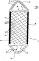
- the embodiment of a fixing and / or holding net 1 according to the invention shown in principle, has a power supply unit 2.
- the power supply unit 2 is formed by two sets of strands 3, 4 which are inclined to one another and each have a plurality of parallel net strings 5 and 6, respectively.
- the power supply unit 2 is provided with an edge belt 7 and 8, respectively.
- the edge belts 7, 8 can be produced in one work step with the power supply unit 2.
- the power supply unit 2 is designed with an elastic edge member 9, 10 on each of the two lateral edge sections.
- the two elastic edge members 9, 10 are designed as belt loops.
- Each belt loop 9, 10 has an edge link section 11 attached to the power supply unit 2 and an edge link section 12 without a network part.
- each belt loop 9, 10 On its rear side facing a receiving or mounting surface on the vehicle side, each belt loop 9, 10 is provided with an anti-slip coating 13 which, in the exemplary embodiment of the fixing and / or holding net according to the invention, consists of discreetly designed anti-slip elements or anti-slip knobs 14.
- the rear side of the elastic edge member 9 or the belt loop 9 and the elastic edge member 10 or the belt loop 10 facing the vehicle-side receiving or mounting surface can be releasably fixed to the vehicle-side receiving or mounting surface.
- the anti-slip coating 13 prevents the edge link section 11 attached to the power supply unit 2 of the fixing and / or holding net 1 from slipping on the vehicle-side receiving or mounting surface.
- the positioning of the fixing and / or holding net 1 on the vehicle-side receiving or mounting surface is based on this easily detachable but permanent fixation of the elastic edge members 9, 10 or belt loops 9, 10 on the vehicle-side receiving or mounting surface, not on the elastic restoring force of the two belt loops 9, 10.
- one and the same fixing and / or holding net 1 can be attached to the vehicle-side receiving or mounting surfaces by means of the belt loops 9, 10, the dimensions of which vary in a comparatively wide range .
- the discrete anti-slip elements or anti-slip knobs 14 are arranged stochastically on the side of the two belt loops or elastic edge members 9, 10 facing the vehicle-side receiving or mounting surface. If uniform adhesion is intended over the entire adhesive or fixing surface, it is of course possible to arrange the anti-slip elements or anti-slip knobs 14 in a pattern that satisfies the respective requirement profile, for example equally spaced both in the longitudinal and in the transverse direction of the elastic edge member 9 , 10.
- the anti-slip coating 13 or its anti-slip elements or knobs can be made of silicone, for example.
- the elastic edge member is designed as an elastic fabric tape made of a textile material, it being sewn to the power supply unit 2 of the fixing and / or holding net 1 in the illustrated embodiment.
Landscapes
- Engineering & Computer Science (AREA)
- Mechanical Engineering (AREA)
- Transportation (AREA)
- Current-Collector Devices For Electrically Propelled Vehicles (AREA)
- Vehicle Step Arrangements And Article Storage (AREA)
- Slide Fasteners, Snap Fasteners, And Hook Fasteners (AREA)
Description
- Die Erfindung bezieht sich auf ein Fixier- und/oder Haltenetz für Fahrzeuge, mit einem Netzteil und zumindest einem elastischen Randglied, das an einem Randabschnitt des Netzteils angebracht ist.
- Derartige Fixier- und/oder Haltenetze kommen in vielfältiger Ausgestaltung in Fahrzeugen, insbesondere in Kraftfahrzeugen, aber auch in Flugzeugen, Schiffen, Eisen- und Straßenbahnen, Omnibussen, Lastkraftwagen etc. zum Einsatz. Üblicherweise sind derartige Fixier- und/oder Haltenetze an einer Aufnahme- bzw. Montagefläche angeordnet und angebracht. Um die Anordnung eines derartigen Fixier- und/oder Haltenetzes an der Aufnahme- bzw. Montagefläche mit einem möglichst geringen technisch-konstruktiven Aufwand zu bewerkstelligen, werden derartige Fixier- und/oder Haltenetze häufig mittels ihrer Randglieder an der Aufnahme- bzw. Montagefläche angebracht, wozu Randglieder des Netzteils beispielsweise in umlaufender Ausgestaltung ausgebildet sind und das die Aufnahme- bzw. Montagefläche ausbildende Wandungsteil umlaufen. Die
GB 2 133 355 A - Ausgehend von dem vorstehend geschilderten Stand der Technik liegt der Erfindung die Aufgabe zugrunde, ein Fixier- und/oder Haltenetz für Fahrzeuge der eingangs geschilderten Gattung derart weiterzubilden, dass es mit einem geringeren technisch-konstruktiven Aufwand und höheren ästhetischen Ansprüchen genügend an einer fahrzeugseitigen Aufnahme- bzw. Montagefläche anord- bzw. fixierbar ist.
- Diese Aufgabe wird erfindungsgemäß dadurch gelöst, dass das elastische Randglied des Netzteils auf seiner einer fahrzeugseitigen Aufnahme- bzw. Montagefläche zugewandten Seite eine Antigleitbeschichtung aufweist, mittels der das elastische Randglied lösbar an der fahrzeugseitigen Aufnahme- bzw. Montagefläche fixierbar ist. Die Fixierung des elastischen Randglieds des Netzteils an der fahrzeugseitigen Aufnahme- bzw. Montagefläche wird nicht - wie im Stand der Technik üblich - aufgrund auf das elastische Randglied einwirkender elastischer Rückstellkräfte bewerkstelligt, sondern aufgrund der Antigleitbeschichtung, mittels der das mit dem Netzteil verbundene elastische Randglied an der fahrzeugseitigen Aufnahme- bzw. Montagefläche fixiert werden kann. Die Fixierung des elastischen Randglieds an der Aufnahme- bzw. Montagefläche ist bei Bedarf in einfacher Weise lösbar, da zwischen der der fahrzeugseitigen Aufnahme- bzw. Montagefläche zugewandten Seite des elastischen Randglieds einerseits und der fahrzeugseitigen Aufnahme- bzw. Montagefläche keine Eingriffsverbindung od.dgl. besteht. Mit einem sehr geringen Kraftaufwand ist das elastische Randglied von der fahrzeugseitigen Aufnahme- bzw. Montagefläche lösbar, falls hierzu der Bedarf besteht.
- Wenn die Antigleitbeschichtung des elastischen Randglieds aus einer Vielzahl diskreter Antigleitelemente, z.B. aus einer Vielzahl Antigleitnoppen, ausgebildet ist, hat das Vorhandensein der Antigleitbeschichtung auf der der fahrzeugseitigen Aufnahme- bzw. Montagefläche zugewandten Seite des elastischen Randglieds keine spürbaren Auswirkungen auf dessen Elastizität, womit hinsichtlich der Werkstoffauswahl für die Antigleitbeschichtung eine größere Bandbreite gegeben ist.
- Wenn die diskreten Antigleitelemente der Antigleitbeschichtung stochastisch auf der der fahrzeugseitigen Aufnahme- bzw. Montagefläche zugewandten Seite des elastischen Randglieds angeordnet sind, kann der Herstellungsaufwand für das mit der Antigleitbeschichtung versehene elastische Randglied möglichst gering gehalten werden.
- Falls eine möglichst über die gesamte an der fahrzeugseitigen Aufnahme- bzw. Montagefläche anliegende Fläche des elastischen Randglieds gleichmäßige Anhaftung desselben an der fahrzeugseitigen Aufnahme- bzw. Montagefläche angestrebt wird, ist es vorteilhaft, wenn die diskreten Antigleitelemente der Antigleitbeschichtung in einem regelmäßigen Muster, z.B. in Längs- und Querrichtung des elastischen Randglieds gleich beabstandet, auf der der fahrzeugseitigen Aufnahme- bzw. Montagefläche zugewandten Seite des elastischen Randglieds angeordnet sind.
- Vorteilhaft lässt sich die Antigleitbeschichtung des elastischen Randglieds aus Silikon ausgestalten. Dieser Werkstoff ist in einfacher Weise verarbeitbar und verfügt im Zusammenwirken mit den üblichen Ausgestaltungen fahrzeugseitiger Aufnahme- bzw. Montageflächen über gute Hafteigenschaften.
- Das elastische Randglied lässt sich vorteilhaft als elastisches Band aus einem textilen Werkstoff ausgestalten. Zweckmäßigerweise ist das elastische Randglied an das Netzteil angenäht.
- Gemäß einer weiteren vorteilhaften Ausführungsform ist das elastische Randglied als Gewebeband ausgebildet.
- Weil das elastische Randglied als Gurtschlaufe ausgebildet ist, wobei die Gurtschlaufe einen an das Netzteil angebrachten Randgliedabschnitt und einen netzteilfreien Randgliedabschnitt aufweist, kann je nach den Abmessungen der fahrzeugseitigen Aufnahme- bzw. Montagefläche in einfacher Weise der an der fahrzeugseitigen Aufnahme- bzw. Montagefläche anhaftende Längenabschnitt der Gurtschlaufe an die betreffende Abmessung der fahrzeugseitigen Aufnahme- bzw. Montagefläche angepasst werden, da die Fixierung des Fixier- und/oder Haltenetzes an der fahrzeugseitigen Aufnahme- bzw. Montagefläche nicht aufgrund der elastischen Rückstellkräfte der Gurtschlaufe bewerkstelligt ist, sondern aufgrund der mittels der Antigleitbeschichtung des als Gurtschlaufe ausgebildeten elastischen Randglieds ausgeübten Haftkräfte. So kann auch im Rahmen der durch das Netzteil vorgegebenen Abmessungen eine Anpassung des Fixier- und/oder Haltenetzes an die Abmessungen der fahrzeugseitigen Aufnahme- bzw. Montagefläche vorgenommen werden.
- Insbesondere wenn die fahrzeugseitigen Aufnahme- bzw. Montageflächen - wie üblich - etwa rechteckig ausgestaltet sind, ist es vorteilhaft, wenn das Netzteil an zwei einander gegenüberliegenden Randabschnitten jeweils ein elastisches Randglied aufweist. In Verbindung mit der Ausgestaltung der beiden elastischen Randglieder als Gurtschlaufen, kann dann ein erfindungsgemäßes Fixier- und/oder Haltenetz an in einer vergleichsweise großen Bandbreite unterschiedlich große fahrzeugseitige Aufnahme- bzw. Montageflächen angebracht werden, wobei die nach der Anbringung des Fixier- und/oder Haltenetzes an der fahrzeugseitigen Aufnahme- bzw. Montagefläche realisierbaren Abmessungen des erfindungsgemäßen Fixier- und/oder Haltenetzes in einer großen Bandbreite an die jeweilige Größe der fahrzeugseitigen Aufnahme- bzw. Montagefläche anpassbar sind. Ursächlich hierfür ist, wie vorstehend bereits erwähnt, dass die Fixierung der Gurtschlaufen und damit des Netzteils des erfindungsgemäßen Fixier- und/oder Haltenetzes an der fahrzeugseitigen Aufnahme- bzw. Montagefläche nicht aufgrund der elastischen Rückstellkräfte des Gurtschlaufenwerkstoffs bewerkstelligt wird, sondern in wesentlichen Teilen durch die Hafteigenschaften der Antigleitbeschichtung. Entsprechend kann ein und dasselbe Fixier- bzw. Haltenetz mit an diesen angebrachten Gurtschlaufen an fahrzeugseitige Aufnahme- bzw. Montageflächen mit einer größeren Bandbreite von Abmessungen angebracht werden, wobei aufgrund der üblicherweise vorgesehenen Flexibilität des Netzteils auch dieses hinsichtlich seiner Abmessungen in einer vergleichsweise großen Bandbreite an die Abmessungen der fahrzeugseitigen Aufnahme- bzw. Montagefläche anpassbar ist.
- Gemäß einer weiteren vorteilhaften Ausführungsform des erfindungsgemäßen Fixier- und/oder Haltenetzes ist dessen Netzteil an zwei anderen einander gegenüberliegenden Randabschnitten jeweils mit einem Randgurt versehen, der gemeinsam mit dem Netzteil hergestellt, vorzugsweise gewebt, ist.
- Im Folgenden wir die Erfindung anhand einer Ausführungsform unter Bezugnahme auf die Figuren näher erläutert. Es zeigen:
- Figur 1
- eine Prinzipdarstellung einer Ausführungsform eines erfindungsgemäßen Fixier- und/oder Haltenetzes für Fahrzeuge in Vorderansicht; und
- Figur 2
- eine Prinzipdarstellung der in
Figur 1 gezeigten Ausführungsform des erfindungsgemäßen Fixier- und/ oder Haltenetzes in Rückansicht, wobei die inFigur 2 dargestellte Rückseite des Fixier- und/oder Haltenetzes der fahrzeugseitigen Aufnahme- bzw. Montagefläche zugewandt ist. - Eine in den
Figuren 1 und2 prinzipiell dargestellte Ausführungsform eines erfindungsgemäßen Fixier- und/oder Haltenetzes 1 hat ein Netzteil 2. Das Netzteil 2 ist durch zwei zueinander geneigt verlaufende Strangscharen 3, 4 gebildet, die jeweils eine Vielzahl zueinander paralleler Netzstränge 5 bzw. 6 aufweisen. - An seinem in den
Figuren 1 und2 oberen Randabschnitt und an seinem in denFiguren 1 und2 unteren Randabschnitt ist das Netzteil 2 jeweils mit einem Randgurt 7 bzw. 8 versehen. Die Randgurte 7, 8 können in einem Arbeitsschritt mit dem Netzteil 2 hergestellt werden. - An den beiden seitlichen Randabschnitten ist das Netzteil 2 jeweils mit einem elastischen Randglied 9, 10 ausgestaltet. Im dargestellten Ausführungsbeispiel des Fixier- und/oder Haltenetzes sind die beiden elastischen Randglieder 9, 10 als Gurtschlaufen ausgebildet.
- Jede Gurtschlaufe 9, 10 hat einen am Netzteil 2 angebrachten Randgliedabschnitt 11 und einen netzteilfreien Randgliedabschnitt 12.
- Auf ihrer einer fahrzeugseitigen Aufnahme- bzw. Montagefläche zugewandten Rückseite ist jede Gurtschlaufe 9, 10 mit einer Antigleitbeschichtung 13 versehen, die im dargestellten Ausführungsbeispiel des erfindungsgemäßen Fixier- und/oder Haltenetzes aus diskret ausgebildeten Antigleitelementen bzw. Antigleitnoppen 14 besteht.
- Mittels der Antigleitnoppen 14 ist die der fahrzeugseitigen Aufnahme- bzw. Montagefläche zugewandte Rückseite des elastischen Randglieds 9 bzw. der Gurtschlaufe 9 und des elastischen Randglieds 10 bzw. der Gurtschlaufe 10 an der fahrzeugseitigen Aufnahme- bzw. Montagefläche lösbar fixierbar. Die Antigleitbeschichtung 13 verhindert ein Rutschen der am Netzteil 2 des Fixier- und/oder Haltenetzes 1 angebrachten Randgliedabschnitts 11 auf der fahrzeugseitigen Aufnahme- bzw. Montagefläche. Die Positionierung des Fixier- und/oder Haltenetzes 1 auf der fahrzeugseitigen Aufnahme- bzw. Montagefläche beruht auf dieser in einfacher Weise lösbaren aber dennoch dauerhaften Fixierung der elastischen Randglieder 9, 10 bzw. Gurtschlaufen 9, 10 an der fahrzeugseitigen Aufnahme- bzw. Montagefläche, nicht auf der elastischen Rückstellkraft der beiden Gurtschlaufen 9, 10. Entsprechend kann mittels der Gurtschlaufen 9, 10 ein und dasselbe Fixier- und/oder Haltenetz 1 an fahrzeugseitige Aufnahme- bzw. Montageflächen angebracht werden, die hinsichtlich ihrer Abmessungen in einer vergleichsweise großen Bandbreite variieren.
- Im dargestellten Ausführungsbeispiel sind die diskreten Antigleitelemente bzw. Antigleitnoppen 14 stochastisch auf der der fahrzeugseitigen Aufnahme- bzw. Montagefläche zugewandten Seite der beiden Gurtschlaufen bzw. elastischen Randglieder 9, 10 angeordnet. Sofern eine über die gesamte Haft- bzw. Fixierfläche gleichmäßige Anhaftung beabsichtigt ist, ist es selbstverständlich möglich, die Antigleitelemente bzw. Antigleitnoppen 14 in einem dem jeweiligen Anforderungsprofil genügenden Muster anzuordnen, beispielsweise gleich beabstandet sowohl in Längs- als auch in Querrichtung des elastischen Randglieds 9, 10.
- Die Antigleitbeschichtung 13 bzw. deren Antigleitelemente oder -noppen können z.B. aus Silikon ausgebildet sein.
- Das elastische Randglied ist im dargestellten Ausführungsbeispiel des Fixier- und/oder Haltenetzes 1 als elastisches Gewebeband aus einem textilen Werkstoff ausgebildet, wobei es im dargestellten Ausführungsbeispiel an das Netzteil 2 des Fixier- und/oder Haltenetzes 1 angenäht ist.
Claims (10)
- Fixier- und/oder Haltenetz für Fahrzeuge, mit einem Netzteil (2) und zumindest einem elastischen Randglied (9, 10), das an einem Randabschnitt des Netzteils (2) angebracht ist und auf seiner einer fahrzeugseitigen Aufnahme- bzw. Montagefläche zugewandten Seite eine Antigleitbeschichtung (13) aufweist, mittels der das elastische Randglied (9, 10) lösbar an der fahrzeugseitigen Aufnahme- bzw. Montagefläche fixierbar ist, dadurch gekennzeichnet, dass das elastische Randglied (9, 10) als Gurtschlaufe (9, 10) ausgebildet ist, wobei die Gurtschlaufe (9, 10) einen an das Netzteil (2) angebrachten Randgliedabschnitt (11) und einen netzteilfreien Randgliedabschnitt (12) aufweist.
- Fixier- und/oder Haltenetz nach Anspruch 1, bei dem die Antigleitbeschichtung (13) des elastischen Randglieds (9, 10) aus einer Vielzahl diskreter Antigleitelemente (14), z.B. Antigleitnoppen, ausgebildet ist.
- Fixier- und/oder Haltenetz nach Anspruch 2, bei dem die diskreten Antigleitelemente (14) der Antigleitbeschichtung (13) stochastisch auf der der fahrzeugseitigen Aufnahme- bzw. Montagefläche zugewandten Seite des elastischen Randglieds (9, 10) angeordnet sind.
- Fixier- und/oder Haltenetz nach Anspruch 2, bei dem die diskreten Antigleitelemente (14) der Antigleitbeschichtung (13) in einem regelmäßigen Muster, z.B. in Längs- und Querrichtung des elastischen Randglieds (9, 10) gleich beabstandet, auf der der fahrzeugseitigen Aufnahme- bzw. Montagefläche zugewandten Seite des elastischen Randglieds (9, 10) angeordnet sind.
- Fixier- und/oder Haltenetz nach einem der Ansprüche 1 bis 4, bei dem die Antigleitbeschichtung (13) des elastischen Randglieds (9, 10) aus Silikon ausgebildet ist.
- Fixier- und/oder Haltenetz nach einem der Ansprüche 1 bis 5, bei dem das elastische Randglied (9, 10) als elastisches Band aus einem textilen Werkstoff ausgebildet ist.
- Fixier- und/oder Haltenetz nach einem der Ansprüche 1 bis 6, bei dem das elastische Randglied (9, 10) an das Netzteil (2) angenäht ist.
- Fixier- und/oder Haltenetz nach einem der Ansprüche 1 bis 7, bei dem das elastische Randglied (9, 10) als Gewebeband ausgebildet ist.
- Fixier- und/oder Haltenetz nach einem der Ansprüche 1 bis 8, bei dem das Netzteil (2) an zwei einander gegenüberliegenden Randabschnitten jeweils ein elastisches Randglied (9, 10) aufweist.
- Fixier- und/oder Haltenetz nach einem der Ansprüche 1 bis 9, bei dem das Netzteil (2) an zwei anderen einander gegenüberliegenden Randabschnitten jeweils einen Randgurt (7, 8) aufweist, der gemeinsam mit dem Netzteil (2) hergestellt ist.
Applications Claiming Priority (1)
| Application Number | Priority Date | Filing Date | Title |
|---|---|---|---|
| DE102018001282 | 2018-02-17 |
Publications (2)
| Publication Number | Publication Date |
|---|---|
| EP3527427A1 EP3527427A1 (de) | 2019-08-21 |
| EP3527427B1 true EP3527427B1 (de) | 2021-03-17 |
Family
ID=65023689
Family Applications (1)
| Application Number | Title | Priority Date | Filing Date |
|---|---|---|---|
| EP19000021.6A Active EP3527427B1 (de) | 2018-02-17 | 2019-01-11 | Fixier- und/oder haltenetz für fahrzeuge |
Country Status (3)
| Country | Link |
|---|---|
| EP (1) | EP3527427B1 (de) |
| ES (1) | ES2874128T3 (de) |
| HU (1) | HUE054487T2 (de) |
Family Cites Families (6)
| Publication number | Priority date | Publication date | Assignee | Title |
|---|---|---|---|---|
| GB2133355B (en) * | 1982-12-16 | 1986-04-30 | John Vernon Lee | A vehicle partition |
| DE29921661U1 (de) * | 1999-12-10 | 2001-04-19 | Nölle-Pepin GmbH & Co. KG, 58332 Schwelm | Halteschleife |
| US7910188B2 (en) * | 2001-07-31 | 2011-03-22 | American Covers, Inc. | Frictional holding pad |
| US6971827B1 (en) * | 2004-09-28 | 2005-12-06 | General Motors Corporation | Apparatus for retaining objects on mounting surfaces |
| DE102006027874A1 (de) * | 2006-06-16 | 2007-12-20 | Bruno Gruber | Haltevorrichtung |
| CN106740536A (zh) * | 2016-12-27 | 2017-05-31 | 重庆长野汽车配件有限公司 | 一种多功能导航仪支架 |
-
2019
- 2019-01-11 EP EP19000021.6A patent/EP3527427B1/de active Active
- 2019-01-11 ES ES19000021T patent/ES2874128T3/es active Active
- 2019-01-11 HU HUE19000021A patent/HUE054487T2/hu unknown
Non-Patent Citations (1)
| Title |
|---|
| None * |
Also Published As
| Publication number | Publication date |
|---|---|
| HUE054487T2 (hu) | 2021-09-28 |
| EP3527427A1 (de) | 2019-08-21 |
| ES2874128T3 (es) | 2021-11-04 |
Similar Documents
| Publication | Publication Date | Title |
|---|---|---|
| EP1438213B2 (de) | Netzanordnung zur montage an einem rahmen | |
| EP2860126A1 (de) | Vorrichtung zur Aufnahme und zum Halten von Gegenständen und zugehöriger Verbindungskörper | |
| WO2017037016A1 (de) | Flugzeugsitzvorrichtung | |
| EP3527427B1 (de) | Fixier- und/oder haltenetz für fahrzeuge | |
| DE102010037754B4 (de) | Vorrichtung zum Festlegen | |
| DE102015201618A1 (de) | Kettenführungselement | |
| DE202015101561U1 (de) | Fangband | |
| DE19714235C2 (de) | Rückenlehne für einen Kraftfahrzeugsitz | |
| DE202012007754U1 (de) | Clip-, Stift- und Halterungsbaugruppe zur Befestigung von Zubehörteilen an Fahrzeugpaneelen | |
| DE102015119542A1 (de) | Sitzanordnung, insbesondere für ein Kraftfahrzeug | |
| DE102012014667A1 (de) | Stützvorrichtung für einen Sitz und damit ausgerüsteter Fahrzeugsitz | |
| DE102008028507B3 (de) | Bezug | |
| DE102009018276A1 (de) | Fahrzeugbauteil in einem Fahrzeuginnenraum sowie eine Verbindungsanordnung zwischen einem Fahrzeugbauteil und einem auf diesem lösbar angeordneten Objekt | |
| DE202009011148U1 (de) | Trägersystem | |
| DE202012100456U1 (de) | Radabdeckung | |
| DE202012009544U1 (de) | Haltenetz zur Montage an einer Befestigungsfläche | |
| DE102013211467A1 (de) | Scheibenbremsklotz für Schienenfahrzeug | |
| DE29919892U1 (de) | Haltenetz | |
| DE202013102879U1 (de) | Verbindungselement zur Befestigung von Zierleisten auf einem Stoßfänger | |
| EP1122124A1 (de) | Gepolsterter Fahrzeugsitz | |
| EP1614554B1 (de) | Spannelementhalterung für Gleitschutzketten | |
| DE102018212893A1 (de) | Nackenkissen und ein Kraftfahrzeug | |
| DE102022103700A1 (de) | Montageclip zum Verbinden von zwei Bauteilen | |
| DE102017006975A1 (de) | Befestigungsvorrichtung zur Befestigung eines Bauteils an einer Fahrzeugstruktur | |
| EP2952391B1 (de) | Trenn- und/oder haltenetz |
Legal Events
| Date | Code | Title | Description |
|---|---|---|---|
| PUAI | Public reference made under article 153(3) epc to a published international application that has entered the european phase |
Free format text: ORIGINAL CODE: 0009012 |
|
| STAA | Information on the status of an ep patent application or granted ep patent |
Free format text: STATUS: THE APPLICATION HAS BEEN PUBLISHED |
|
| AK | Designated contracting states |
Kind code of ref document: A1 Designated state(s): AL AT BE BG CH CY CZ DE DK EE ES FI FR GB GR HR HU IE IS IT LI LT LU LV MC MK MT NL NO PL PT RO RS SE SI SK SM TR |
|
| AX | Request for extension of the european patent |
Extension state: BA ME |
|
| STAA | Information on the status of an ep patent application or granted ep patent |
Free format text: STATUS: REQUEST FOR EXAMINATION WAS MADE |
|
| 17P | Request for examination filed |
Effective date: 20200114 |
|
| RBV | Designated contracting states (corrected) |
Designated state(s): AL AT BE BG CH CY CZ DE DK EE ES FI FR GB GR HR HU IE IS IT LI LT LU LV MC MK MT NL NO PL PT RO RS SE SI SK SM TR |
|
| STAA | Information on the status of an ep patent application or granted ep patent |
Free format text: STATUS: EXAMINATION IS IN PROGRESS |
|
| 17Q | First examination report despatched |
Effective date: 20200306 |
|
| GRAP | Despatch of communication of intention to grant a patent |
Free format text: ORIGINAL CODE: EPIDOSNIGR1 |
|
| STAA | Information on the status of an ep patent application or granted ep patent |
Free format text: STATUS: GRANT OF PATENT IS INTENDED |
|
| INTG | Intention to grant announced |
Effective date: 20201029 |
|
| GRAS | Grant fee paid |
Free format text: ORIGINAL CODE: EPIDOSNIGR3 |
|
| GRAA | (expected) grant |
Free format text: ORIGINAL CODE: 0009210 |
|
| STAA | Information on the status of an ep patent application or granted ep patent |
Free format text: STATUS: THE PATENT HAS BEEN GRANTED |
|
| AK | Designated contracting states |
Kind code of ref document: B1 Designated state(s): AL AT BE BG CH CY CZ DE DK EE ES FI FR GB GR HR HU IE IS IT LI LT LU LV MC MK MT NL NO PL PT RO RS SE SI SK SM TR |
|
| REG | Reference to a national code |
Ref country code: GB Ref legal event code: FG4D Free format text: NOT ENGLISH |
|
| REG | Reference to a national code |
Ref country code: CH Ref legal event code: EP |
|
| REG | Reference to a national code |
Ref country code: DE Ref legal event code: R096 Ref document number: 502019000977 Country of ref document: DE |
|
| REG | Reference to a national code |
Ref country code: IE Ref legal event code: FG4D Free format text: LANGUAGE OF EP DOCUMENT: GERMAN |
|
| REG | Reference to a national code |
Ref country code: AT Ref legal event code: REF Ref document number: 1371939 Country of ref document: AT Kind code of ref document: T Effective date: 20210415 |
|
| REG | Reference to a national code |
Ref country code: NL Ref legal event code: FP |
|
| REG | Reference to a national code |
Ref country code: LT Ref legal event code: MG9D |
|
| PG25 | Lapsed in a contracting state [announced via postgrant information from national office to epo] |
Ref country code: NO Free format text: LAPSE BECAUSE OF FAILURE TO SUBMIT A TRANSLATION OF THE DESCRIPTION OR TO PAY THE FEE WITHIN THE PRESCRIBED TIME-LIMIT Effective date: 20210617 Ref country code: HR Free format text: LAPSE BECAUSE OF FAILURE TO SUBMIT A TRANSLATION OF THE DESCRIPTION OR TO PAY THE FEE WITHIN THE PRESCRIBED TIME-LIMIT Effective date: 20210317 Ref country code: GR Free format text: LAPSE BECAUSE OF FAILURE TO SUBMIT A TRANSLATION OF THE DESCRIPTION OR TO PAY THE FEE WITHIN THE PRESCRIBED TIME-LIMIT Effective date: 20210618 Ref country code: FI Free format text: LAPSE BECAUSE OF FAILURE TO SUBMIT A TRANSLATION OF THE DESCRIPTION OR TO PAY THE FEE WITHIN THE PRESCRIBED TIME-LIMIT Effective date: 20210317 Ref country code: BG Free format text: LAPSE BECAUSE OF FAILURE TO SUBMIT A TRANSLATION OF THE DESCRIPTION OR TO PAY THE FEE WITHIN THE PRESCRIBED TIME-LIMIT Effective date: 20210617 |
|
| PG25 | Lapsed in a contracting state [announced via postgrant information from national office to epo] |
Ref country code: LV Free format text: LAPSE BECAUSE OF FAILURE TO SUBMIT A TRANSLATION OF THE DESCRIPTION OR TO PAY THE FEE WITHIN THE PRESCRIBED TIME-LIMIT Effective date: 20210317 Ref country code: RS Free format text: LAPSE BECAUSE OF FAILURE TO SUBMIT A TRANSLATION OF THE DESCRIPTION OR TO PAY THE FEE WITHIN THE PRESCRIBED TIME-LIMIT Effective date: 20210317 Ref country code: SE Free format text: LAPSE BECAUSE OF FAILURE TO SUBMIT A TRANSLATION OF THE DESCRIPTION OR TO PAY THE FEE WITHIN THE PRESCRIBED TIME-LIMIT Effective date: 20210317 |
|
| REG | Reference to a national code |
Ref country code: HU Ref legal event code: AG4A Ref document number: E054487 Country of ref document: HU |
|
| PG25 | Lapsed in a contracting state [announced via postgrant information from national office to epo] |
Ref country code: SM Free format text: LAPSE BECAUSE OF FAILURE TO SUBMIT A TRANSLATION OF THE DESCRIPTION OR TO PAY THE FEE WITHIN THE PRESCRIBED TIME-LIMIT Effective date: 20210317 Ref country code: LT Free format text: LAPSE BECAUSE OF FAILURE TO SUBMIT A TRANSLATION OF THE DESCRIPTION OR TO PAY THE FEE WITHIN THE PRESCRIBED TIME-LIMIT Effective date: 20210317 Ref country code: EE Free format text: LAPSE BECAUSE OF FAILURE TO SUBMIT A TRANSLATION OF THE DESCRIPTION OR TO PAY THE FEE WITHIN THE PRESCRIBED TIME-LIMIT Effective date: 20210317 |
|
| PG25 | Lapsed in a contracting state [announced via postgrant information from national office to epo] |
Ref country code: SK Free format text: LAPSE BECAUSE OF FAILURE TO SUBMIT A TRANSLATION OF THE DESCRIPTION OR TO PAY THE FEE WITHIN THE PRESCRIBED TIME-LIMIT Effective date: 20210317 Ref country code: RO Free format text: LAPSE BECAUSE OF FAILURE TO SUBMIT A TRANSLATION OF THE DESCRIPTION OR TO PAY THE FEE WITHIN THE PRESCRIBED TIME-LIMIT Effective date: 20210317 Ref country code: PT Free format text: LAPSE BECAUSE OF FAILURE TO SUBMIT A TRANSLATION OF THE DESCRIPTION OR TO PAY THE FEE WITHIN THE PRESCRIBED TIME-LIMIT Effective date: 20210719 Ref country code: PL Free format text: LAPSE BECAUSE OF FAILURE TO SUBMIT A TRANSLATION OF THE DESCRIPTION OR TO PAY THE FEE WITHIN THE PRESCRIBED TIME-LIMIT Effective date: 20210317 Ref country code: IS Free format text: LAPSE BECAUSE OF FAILURE TO SUBMIT A TRANSLATION OF THE DESCRIPTION OR TO PAY THE FEE WITHIN THE PRESCRIBED TIME-LIMIT Effective date: 20210717 |
|
| REG | Reference to a national code |
Ref country code: DE Ref legal event code: R097 Ref document number: 502019000977 Country of ref document: DE |
|
| PLBE | No opposition filed within time limit |
Free format text: ORIGINAL CODE: 0009261 |
|
| STAA | Information on the status of an ep patent application or granted ep patent |
Free format text: STATUS: NO OPPOSITION FILED WITHIN TIME LIMIT |
|
| PG25 | Lapsed in a contracting state [announced via postgrant information from national office to epo] |
Ref country code: AL Free format text: LAPSE BECAUSE OF FAILURE TO SUBMIT A TRANSLATION OF THE DESCRIPTION OR TO PAY THE FEE WITHIN THE PRESCRIBED TIME-LIMIT Effective date: 20210317 Ref country code: DK Free format text: LAPSE BECAUSE OF FAILURE TO SUBMIT A TRANSLATION OF THE DESCRIPTION OR TO PAY THE FEE WITHIN THE PRESCRIBED TIME-LIMIT Effective date: 20210317 |
|
| 26N | No opposition filed |
Effective date: 20211220 |
|
| PG25 | Lapsed in a contracting state [announced via postgrant information from national office to epo] |
Ref country code: SI Free format text: LAPSE BECAUSE OF FAILURE TO SUBMIT A TRANSLATION OF THE DESCRIPTION OR TO PAY THE FEE WITHIN THE PRESCRIBED TIME-LIMIT Effective date: 20210317 |
|
| PG25 | Lapsed in a contracting state [announced via postgrant information from national office to epo] |
Ref country code: IS Free format text: LAPSE BECAUSE OF FAILURE TO SUBMIT A TRANSLATION OF THE DESCRIPTION OR TO PAY THE FEE WITHIN THE PRESCRIBED TIME-LIMIT Effective date: 20210717 |
|
| PG25 | Lapsed in a contracting state [announced via postgrant information from national office to epo] |
Ref country code: MC Free format text: LAPSE BECAUSE OF FAILURE TO SUBMIT A TRANSLATION OF THE DESCRIPTION OR TO PAY THE FEE WITHIN THE PRESCRIBED TIME-LIMIT Effective date: 20210317 |
|
| REG | Reference to a national code |
Ref country code: CH Ref legal event code: PL |
|
| PG25 | Lapsed in a contracting state [announced via postgrant information from national office to epo] |
Ref country code: LU Free format text: LAPSE BECAUSE OF NON-PAYMENT OF DUE FEES Effective date: 20220111 |
|
| PG25 | Lapsed in a contracting state [announced via postgrant information from national office to epo] |
Ref country code: LI Free format text: LAPSE BECAUSE OF NON-PAYMENT OF DUE FEES Effective date: 20220131 Ref country code: CH Free format text: LAPSE BECAUSE OF NON-PAYMENT OF DUE FEES Effective date: 20220131 |
|
| PG25 | Lapsed in a contracting state [announced via postgrant information from national office to epo] |
Ref country code: IE Free format text: LAPSE BECAUSE OF NON-PAYMENT OF DUE FEES Effective date: 20220111 |
|
| REG | Reference to a national code |
Ref country code: DE Ref legal event code: R082 Ref document number: 502019000977 Country of ref document: DE Representative=s name: MOSER GOETZE & PARTNER PATENTANWAELTE MBB, DE |
|
| PG25 | Lapsed in a contracting state [announced via postgrant information from national office to epo] |
Ref country code: MK Free format text: LAPSE BECAUSE OF FAILURE TO SUBMIT A TRANSLATION OF THE DESCRIPTION OR TO PAY THE FEE WITHIN THE PRESCRIBED TIME-LIMIT Effective date: 20210317 Ref country code: CY Free format text: LAPSE BECAUSE OF FAILURE TO SUBMIT A TRANSLATION OF THE DESCRIPTION OR TO PAY THE FEE WITHIN THE PRESCRIBED TIME-LIMIT Effective date: 20210317 |
|
| PG25 | Lapsed in a contracting state [announced via postgrant information from national office to epo] |
Ref country code: MT Free format text: LAPSE BECAUSE OF FAILURE TO SUBMIT A TRANSLATION OF THE DESCRIPTION OR TO PAY THE FEE WITHIN THE PRESCRIBED TIME-LIMIT Effective date: 20210317 |
|
| PGFP | Annual fee paid to national office [announced via postgrant information from national office to epo] |
Ref country code: NL Payment date: 20250122 Year of fee payment: 7 |
|
| PGFP | Annual fee paid to national office [announced via postgrant information from national office to epo] |
Ref country code: HU Payment date: 20250111 Year of fee payment: 7 |
|
| PGFP | Annual fee paid to national office [announced via postgrant information from national office to epo] |
Ref country code: DE Payment date: 20241216 Year of fee payment: 7 |
|
| PGFP | Annual fee paid to national office [announced via postgrant information from national office to epo] |
Ref country code: ES Payment date: 20250214 Year of fee payment: 7 |
|
| PGFP | Annual fee paid to national office [announced via postgrant information from national office to epo] |
Ref country code: BE Payment date: 20250121 Year of fee payment: 7 Ref country code: AT Payment date: 20250120 Year of fee payment: 7 |
|
| PGFP | Annual fee paid to national office [announced via postgrant information from national office to epo] |
Ref country code: FR Payment date: 20250122 Year of fee payment: 7 Ref country code: CZ Payment date: 20241231 Year of fee payment: 7 |
|
| PGFP | Annual fee paid to national office [announced via postgrant information from national office to epo] |
Ref country code: GB Payment date: 20250123 Year of fee payment: 7 Ref country code: IT Payment date: 20250131 Year of fee payment: 7 |
|
| PGFP | Annual fee paid to national office [announced via postgrant information from national office to epo] |
Ref country code: TR Payment date: 20250107 Year of fee payment: 7 |