EP3527309A1 - Surface-coated cutting tool - Google Patents
Surface-coated cutting tool Download PDFInfo
- Publication number
- EP3527309A1 EP3527309A1 EP17860696.8A EP17860696A EP3527309A1 EP 3527309 A1 EP3527309 A1 EP 3527309A1 EP 17860696 A EP17860696 A EP 17860696A EP 3527309 A1 EP3527309 A1 EP 3527309A1
- Authority
- EP
- European Patent Office
- Prior art keywords
- layer
- substrate
- thickness
- coating
- cutting tool
- Prior art date
- Legal status (The legal status is an assumption and is not a legal conclusion. Google has not performed a legal analysis and makes no representation as to the accuracy of the status listed.)
- Withdrawn
Links
- 238000005520 cutting process Methods 0.000 title claims abstract description 179
- 239000000463 material Substances 0.000 claims abstract description 92
- 239000000758 substrate Substances 0.000 claims abstract description 89
- 239000011248 coating agent Substances 0.000 claims abstract description 77
- 238000000576 coating method Methods 0.000 claims abstract description 77
- 239000000203 mixture Substances 0.000 claims abstract description 36
- 229910052782 aluminium Inorganic materials 0.000 claims abstract description 26
- 229910052757 nitrogen Inorganic materials 0.000 claims abstract description 23
- 229910052719 titanium Inorganic materials 0.000 claims abstract description 17
- 239000000919 ceramic Substances 0.000 claims abstract description 16
- 229910052804 chromium Inorganic materials 0.000 claims abstract description 13
- 150000001875 compounds Chemical class 0.000 claims description 40
- 229910000760 Hardened steel Inorganic materials 0.000 claims description 8
- 229910052582 BN Inorganic materials 0.000 claims description 5
- PZNSFCLAULLKQX-UHFFFAOYSA-N Boron nitride Chemical compound N#B PZNSFCLAULLKQX-UHFFFAOYSA-N 0.000 claims description 5
- 239000010410 layer Substances 0.000 description 244
- 239000002245 particle Substances 0.000 description 34
- 238000000034 method Methods 0.000 description 27
- 230000015572 biosynthetic process Effects 0.000 description 20
- ATJFFYVFTNAWJD-UHFFFAOYSA-N Tin Chemical compound [Sn] ATJFFYVFTNAWJD-UHFFFAOYSA-N 0.000 description 18
- 230000000052 comparative effect Effects 0.000 description 16
- 239000011230 binding agent Substances 0.000 description 15
- 238000003754 machining Methods 0.000 description 14
- 239000002344 surface layer Substances 0.000 description 14
- 229910052718 tin Inorganic materials 0.000 description 13
- 238000004519 manufacturing process Methods 0.000 description 11
- 229910016459 AlB2 Inorganic materials 0.000 description 10
- QYEXBYZXHDUPRC-UHFFFAOYSA-N B#[Ti]#B Chemical compound B#[Ti]#B QYEXBYZXHDUPRC-UHFFFAOYSA-N 0.000 description 10
- 229910033181 TiB2 Inorganic materials 0.000 description 10
- 239000010730 cutting oil Substances 0.000 description 10
- 229910052751 metal Inorganic materials 0.000 description 10
- 239000002184 metal Substances 0.000 description 10
- 239000000843 powder Substances 0.000 description 10
- 229910017083 AlN Inorganic materials 0.000 description 9
- PNEYBMLMFCGWSK-UHFFFAOYSA-N aluminium oxide Inorganic materials [O-2].[O-2].[O-2].[Al+3].[Al+3] PNEYBMLMFCGWSK-UHFFFAOYSA-N 0.000 description 9
- 229910052593 corundum Inorganic materials 0.000 description 9
- 239000007789 gas Substances 0.000 description 9
- 229910001845 yogo sapphire Inorganic materials 0.000 description 9
- 229910010037 TiAlN Inorganic materials 0.000 description 8
- MCMNRKCIXSYSNV-UHFFFAOYSA-N Zirconium dioxide Chemical compound O=[Zr]=O MCMNRKCIXSYSNV-UHFFFAOYSA-N 0.000 description 8
- 230000000694 effects Effects 0.000 description 8
- 238000002156 mixing Methods 0.000 description 7
- 229910052721 tungsten Inorganic materials 0.000 description 7
- 238000010891 electric arc Methods 0.000 description 6
- 229910052796 boron Inorganic materials 0.000 description 5
- 239000008199 coating composition Substances 0.000 description 5
- 238000010276 construction Methods 0.000 description 5
- 238000011156 evaluation Methods 0.000 description 5
- 229910052755 nonmetal Inorganic materials 0.000 description 5
- 229910052760 oxygen Inorganic materials 0.000 description 5
- 230000003746 surface roughness Effects 0.000 description 5
- 238000012360 testing method Methods 0.000 description 5
- PIGFYZPCRLYGLF-UHFFFAOYSA-N Aluminum nitride Chemical compound [Al]#N PIGFYZPCRLYGLF-UHFFFAOYSA-N 0.000 description 4
- 238000002441 X-ray diffraction Methods 0.000 description 4
- 229910052799 carbon Inorganic materials 0.000 description 4
- 238000005530 etching Methods 0.000 description 4
- 238000010438 heat treatment Methods 0.000 description 4
- 229910052758 niobium Inorganic materials 0.000 description 4
- 229910052710 silicon Inorganic materials 0.000 description 4
- 229910052720 vanadium Inorganic materials 0.000 description 4
- 239000010953 base metal Substances 0.000 description 3
- 230000001186 cumulative effect Effects 0.000 description 3
- 229910052735 hafnium Inorganic materials 0.000 description 3
- 150000002500 ions Chemical class 0.000 description 3
- 238000001883 metal evaporation Methods 0.000 description 3
- 238000003801 milling Methods 0.000 description 3
- 229910052750 molybdenum Inorganic materials 0.000 description 3
- 238000005240 physical vapour deposition Methods 0.000 description 3
- 239000012495 reaction gas Substances 0.000 description 3
- 238000004544 sputter deposition Methods 0.000 description 3
- 229910052715 tantalum Inorganic materials 0.000 description 3
- 229910052726 zirconium Inorganic materials 0.000 description 3
- 229910021280 Co3C Inorganic materials 0.000 description 2
- 229910034327 TiC Inorganic materials 0.000 description 2
- -1 and the like) Inorganic materials 0.000 description 2
- 238000005219 brazing Methods 0.000 description 2
- 239000002775 capsule Substances 0.000 description 2
- 238000005229 chemical vapour deposition Methods 0.000 description 2
- QDOXWKRWXJOMAK-UHFFFAOYSA-N dichromium trioxide Chemical compound O=[Cr]O[Cr]=O QDOXWKRWXJOMAK-UHFFFAOYSA-N 0.000 description 2
- 238000009826 distribution Methods 0.000 description 2
- 230000008020 evaporation Effects 0.000 description 2
- 238000001704 evaporation Methods 0.000 description 2
- 230000001747 exhibiting effect Effects 0.000 description 2
- 229910000765 intermetallic Inorganic materials 0.000 description 2
- 238000007733 ion plating Methods 0.000 description 2
- 150000004767 nitrides Chemical class 0.000 description 2
- 238000012545 processing Methods 0.000 description 2
- 238000000926 separation method Methods 0.000 description 2
- 238000005245 sintering Methods 0.000 description 2
- 230000001629 suppression Effects 0.000 description 2
- WFKWXMTUELFFGS-UHFFFAOYSA-N tungsten Chemical compound [W] WFKWXMTUELFFGS-UHFFFAOYSA-N 0.000 description 2
- 239000010937 tungsten Substances 0.000 description 2
- 229910019918 CrB2 Inorganic materials 0.000 description 1
- 229910052581 Si3N4 Inorganic materials 0.000 description 1
- 230000005540 biological transmission Effects 0.000 description 1
- 238000006243 chemical reaction Methods 0.000 description 1
- 230000002301 combined effect Effects 0.000 description 1
- 230000003247 decreasing effect Effects 0.000 description 1
- 238000011161 development Methods 0.000 description 1
- 238000007599 discharging Methods 0.000 description 1
- 238000005553 drilling Methods 0.000 description 1
- 229910021480 group 4 element Inorganic materials 0.000 description 1
- 229910021478 group 5 element Inorganic materials 0.000 description 1
- 229910021476 group 6 element Inorganic materials 0.000 description 1
- 230000003993 interaction Effects 0.000 description 1
- 238000010884 ion-beam technique Methods 0.000 description 1
- 238000005461 lubrication Methods 0.000 description 1
- 238000012986 modification Methods 0.000 description 1
- 230000004048 modification Effects 0.000 description 1
- 230000003647 oxidation Effects 0.000 description 1
- 238000007254 oxidation reaction Methods 0.000 description 1
- 230000000737 periodic effect Effects 0.000 description 1
- 230000002093 peripheral effect Effects 0.000 description 1
- 238000002360 preparation method Methods 0.000 description 1
- 238000004451 qualitative analysis Methods 0.000 description 1
- 238000004626 scanning electron microscopy Methods 0.000 description 1
- 238000000550 scanning electron microscopy energy dispersive X-ray spectroscopy Methods 0.000 description 1
- 239000002356 single layer Substances 0.000 description 1
- 239000011343 solid material Substances 0.000 description 1
- 239000000126 substance Substances 0.000 description 1
- 238000007740 vapor deposition Methods 0.000 description 1
Images

Classifications
-
- C—CHEMISTRY; METALLURGY
- C04—CEMENTS; CONCRETE; ARTIFICIAL STONE; CERAMICS; REFRACTORIES
- C04B—LIME, MAGNESIA; SLAG; CEMENTS; COMPOSITIONS THEREOF, e.g. MORTARS, CONCRETE OR LIKE BUILDING MATERIALS; ARTIFICIAL STONE; CERAMICS; REFRACTORIES; TREATMENT OF NATURAL STONE
- C04B41/00—After-treatment of mortars, concrete, artificial stone or ceramics; Treatment of natural stone
- C04B41/80—After-treatment of mortars, concrete, artificial stone or ceramics; Treatment of natural stone of only ceramics
- C04B41/81—Coating or impregnation
- C04B41/89—Coating or impregnation for obtaining at least two superposed coatings having different compositions
-
- C—CHEMISTRY; METALLURGY
- C04—CEMENTS; CONCRETE; ARTIFICIAL STONE; CERAMICS; REFRACTORIES
- C04B—LIME, MAGNESIA; SLAG; CEMENTS; COMPOSITIONS THEREOF, e.g. MORTARS, CONCRETE OR LIKE BUILDING MATERIALS; ARTIFICIAL STONE; CERAMICS; REFRACTORIES; TREATMENT OF NATURAL STONE
- C04B41/00—After-treatment of mortars, concrete, artificial stone or ceramics; Treatment of natural stone
- C04B41/009—After-treatment of mortars, concrete, artificial stone or ceramics; Treatment of natural stone characterised by the material treated
-
- B—PERFORMING OPERATIONS; TRANSPORTING
- B23—MACHINE TOOLS; METAL-WORKING NOT OTHERWISE PROVIDED FOR
- B23B—TURNING; BORING
- B23B27/00—Tools for turning or boring machines; Tools of a similar kind in general; Accessories therefor
- B23B27/14—Cutting tools of which the bits or tips or cutting inserts are of special material
-
- B—PERFORMING OPERATIONS; TRANSPORTING
- B23—MACHINE TOOLS; METAL-WORKING NOT OTHERWISE PROVIDED FOR
- B23B—TURNING; BORING
- B23B51/00—Tools for drilling machines
-
- B—PERFORMING OPERATIONS; TRANSPORTING
- B23—MACHINE TOOLS; METAL-WORKING NOT OTHERWISE PROVIDED FOR
- B23F—MAKING GEARS OR TOOTHED RACKS
- B23F21/00—Tools specially adapted for use in machines for manufacturing gear teeth
-
- C—CHEMISTRY; METALLURGY
- C04—CEMENTS; CONCRETE; ARTIFICIAL STONE; CERAMICS; REFRACTORIES
- C04B—LIME, MAGNESIA; SLAG; CEMENTS; COMPOSITIONS THEREOF, e.g. MORTARS, CONCRETE OR LIKE BUILDING MATERIALS; ARTIFICIAL STONE; CERAMICS; REFRACTORIES; TREATMENT OF NATURAL STONE
- C04B41/00—After-treatment of mortars, concrete, artificial stone or ceramics; Treatment of natural stone
- C04B41/45—Coating or impregnating, e.g. injection in masonry, partial coating of green or fired ceramics, organic coating compositions for adhering together two concrete elements
- C04B41/50—Coating or impregnating, e.g. injection in masonry, partial coating of green or fired ceramics, organic coating compositions for adhering together two concrete elements with inorganic materials
- C04B41/5053—Coating or impregnating, e.g. injection in masonry, partial coating of green or fired ceramics, organic coating compositions for adhering together two concrete elements with inorganic materials non-oxide ceramics
- C04B41/5062—Borides, Nitrides or Silicides
- C04B41/5068—Titanium nitride
-
- C—CHEMISTRY; METALLURGY
- C04—CEMENTS; CONCRETE; ARTIFICIAL STONE; CERAMICS; REFRACTORIES
- C04B—LIME, MAGNESIA; SLAG; CEMENTS; COMPOSITIONS THEREOF, e.g. MORTARS, CONCRETE OR LIKE BUILDING MATERIALS; ARTIFICIAL STONE; CERAMICS; REFRACTORIES; TREATMENT OF NATURAL STONE
- C04B41/00—After-treatment of mortars, concrete, artificial stone or ceramics; Treatment of natural stone
- C04B41/45—Coating or impregnating, e.g. injection in masonry, partial coating of green or fired ceramics, organic coating compositions for adhering together two concrete elements
- C04B41/52—Multiple coating or impregnating multiple coating or impregnating with the same composition or with compositions only differing in the concentration of the constituents, is classified as single coating or impregnation
-
- C—CHEMISTRY; METALLURGY
- C23—COATING METALLIC MATERIAL; COATING MATERIAL WITH METALLIC MATERIAL; CHEMICAL SURFACE TREATMENT; DIFFUSION TREATMENT OF METALLIC MATERIAL; COATING BY VACUUM EVAPORATION, BY SPUTTERING, BY ION IMPLANTATION OR BY CHEMICAL VAPOUR DEPOSITION, IN GENERAL; INHIBITING CORROSION OF METALLIC MATERIAL OR INCRUSTATION IN GENERAL
- C23C—COATING METALLIC MATERIAL; COATING MATERIAL WITH METALLIC MATERIAL; SURFACE TREATMENT OF METALLIC MATERIAL BY DIFFUSION INTO THE SURFACE, BY CHEMICAL CONVERSION OR SUBSTITUTION; COATING BY VACUUM EVAPORATION, BY SPUTTERING, BY ION IMPLANTATION OR BY CHEMICAL VAPOUR DEPOSITION, IN GENERAL
- C23C14/00—Coating by vacuum evaporation, by sputtering or by ion implantation of the coating forming material
- C23C14/06—Coating by vacuum evaporation, by sputtering or by ion implantation of the coating forming material characterised by the coating material
- C23C14/0641—Nitrides
-
- C—CHEMISTRY; METALLURGY
- C23—COATING METALLIC MATERIAL; COATING MATERIAL WITH METALLIC MATERIAL; CHEMICAL SURFACE TREATMENT; DIFFUSION TREATMENT OF METALLIC MATERIAL; COATING BY VACUUM EVAPORATION, BY SPUTTERING, BY ION IMPLANTATION OR BY CHEMICAL VAPOUR DEPOSITION, IN GENERAL; INHIBITING CORROSION OF METALLIC MATERIAL OR INCRUSTATION IN GENERAL
- C23C—COATING METALLIC MATERIAL; COATING MATERIAL WITH METALLIC MATERIAL; SURFACE TREATMENT OF METALLIC MATERIAL BY DIFFUSION INTO THE SURFACE, BY CHEMICAL CONVERSION OR SUBSTITUTION; COATING BY VACUUM EVAPORATION, BY SPUTTERING, BY ION IMPLANTATION OR BY CHEMICAL VAPOUR DEPOSITION, IN GENERAL
- C23C14/00—Coating by vacuum evaporation, by sputtering or by ion implantation of the coating forming material
- C23C14/22—Coating by vacuum evaporation, by sputtering or by ion implantation of the coating forming material characterised by the process of coating
- C23C14/24—Vacuum evaporation
- C23C14/32—Vacuum evaporation by explosion; by evaporation and subsequent ionisation of the vapours, e.g. ion-plating
- C23C14/325—Electric arc evaporation
-
- C—CHEMISTRY; METALLURGY
- C23—COATING METALLIC MATERIAL; COATING MATERIAL WITH METALLIC MATERIAL; CHEMICAL SURFACE TREATMENT; DIFFUSION TREATMENT OF METALLIC MATERIAL; COATING BY VACUUM EVAPORATION, BY SPUTTERING, BY ION IMPLANTATION OR BY CHEMICAL VAPOUR DEPOSITION, IN GENERAL; INHIBITING CORROSION OF METALLIC MATERIAL OR INCRUSTATION IN GENERAL
- C23C—COATING METALLIC MATERIAL; COATING MATERIAL WITH METALLIC MATERIAL; SURFACE TREATMENT OF METALLIC MATERIAL BY DIFFUSION INTO THE SURFACE, BY CHEMICAL CONVERSION OR SUBSTITUTION; COATING BY VACUUM EVAPORATION, BY SPUTTERING, BY ION IMPLANTATION OR BY CHEMICAL VAPOUR DEPOSITION, IN GENERAL
- C23C28/00—Coating for obtaining at least two superposed coatings either by methods not provided for in a single one of groups C23C2/00 - C23C26/00 or by combinations of methods provided for in subclasses C23C and C25C or C25D
- C23C28/04—Coating for obtaining at least two superposed coatings either by methods not provided for in a single one of groups C23C2/00 - C23C26/00 or by combinations of methods provided for in subclasses C23C and C25C or C25D only coatings of inorganic non-metallic material
- C23C28/042—Coating for obtaining at least two superposed coatings either by methods not provided for in a single one of groups C23C2/00 - C23C26/00 or by combinations of methods provided for in subclasses C23C and C25C or C25D only coatings of inorganic non-metallic material including a refractory ceramic layer, e.g. refractory metal oxides, ZrO2, rare earth oxides
-
- C—CHEMISTRY; METALLURGY
- C23—COATING METALLIC MATERIAL; COATING MATERIAL WITH METALLIC MATERIAL; CHEMICAL SURFACE TREATMENT; DIFFUSION TREATMENT OF METALLIC MATERIAL; COATING BY VACUUM EVAPORATION, BY SPUTTERING, BY ION IMPLANTATION OR BY CHEMICAL VAPOUR DEPOSITION, IN GENERAL; INHIBITING CORROSION OF METALLIC MATERIAL OR INCRUSTATION IN GENERAL
- C23C—COATING METALLIC MATERIAL; COATING MATERIAL WITH METALLIC MATERIAL; SURFACE TREATMENT OF METALLIC MATERIAL BY DIFFUSION INTO THE SURFACE, BY CHEMICAL CONVERSION OR SUBSTITUTION; COATING BY VACUUM EVAPORATION, BY SPUTTERING, BY ION IMPLANTATION OR BY CHEMICAL VAPOUR DEPOSITION, IN GENERAL
- C23C28/00—Coating for obtaining at least two superposed coatings either by methods not provided for in a single one of groups C23C2/00 - C23C26/00 or by combinations of methods provided for in subclasses C23C and C25C or C25D
- C23C28/04—Coating for obtaining at least two superposed coatings either by methods not provided for in a single one of groups C23C2/00 - C23C26/00 or by combinations of methods provided for in subclasses C23C and C25C or C25D only coatings of inorganic non-metallic material
- C23C28/044—Coating for obtaining at least two superposed coatings either by methods not provided for in a single one of groups C23C2/00 - C23C26/00 or by combinations of methods provided for in subclasses C23C and C25C or C25D only coatings of inorganic non-metallic material coatings specially adapted for cutting tools or wear applications
-
- C—CHEMISTRY; METALLURGY
- C23—COATING METALLIC MATERIAL; COATING MATERIAL WITH METALLIC MATERIAL; CHEMICAL SURFACE TREATMENT; DIFFUSION TREATMENT OF METALLIC MATERIAL; COATING BY VACUUM EVAPORATION, BY SPUTTERING, BY ION IMPLANTATION OR BY CHEMICAL VAPOUR DEPOSITION, IN GENERAL; INHIBITING CORROSION OF METALLIC MATERIAL OR INCRUSTATION IN GENERAL
- C23C—COATING METALLIC MATERIAL; COATING MATERIAL WITH METALLIC MATERIAL; SURFACE TREATMENT OF METALLIC MATERIAL BY DIFFUSION INTO THE SURFACE, BY CHEMICAL CONVERSION OR SUBSTITUTION; COATING BY VACUUM EVAPORATION, BY SPUTTERING, BY ION IMPLANTATION OR BY CHEMICAL VAPOUR DEPOSITION, IN GENERAL
- C23C28/00—Coating for obtaining at least two superposed coatings either by methods not provided for in a single one of groups C23C2/00 - C23C26/00 or by combinations of methods provided for in subclasses C23C and C25C or C25D
- C23C28/40—Coatings including alternating layers following a pattern, a periodic or defined repetition
-
- C—CHEMISTRY; METALLURGY
- C23—COATING METALLIC MATERIAL; COATING MATERIAL WITH METALLIC MATERIAL; CHEMICAL SURFACE TREATMENT; DIFFUSION TREATMENT OF METALLIC MATERIAL; COATING BY VACUUM EVAPORATION, BY SPUTTERING, BY ION IMPLANTATION OR BY CHEMICAL VAPOUR DEPOSITION, IN GENERAL; INHIBITING CORROSION OF METALLIC MATERIAL OR INCRUSTATION IN GENERAL
- C23C—COATING METALLIC MATERIAL; COATING MATERIAL WITH METALLIC MATERIAL; SURFACE TREATMENT OF METALLIC MATERIAL BY DIFFUSION INTO THE SURFACE, BY CHEMICAL CONVERSION OR SUBSTITUTION; COATING BY VACUUM EVAPORATION, BY SPUTTERING, BY ION IMPLANTATION OR BY CHEMICAL VAPOUR DEPOSITION, IN GENERAL
- C23C28/00—Coating for obtaining at least two superposed coatings either by methods not provided for in a single one of groups C23C2/00 - C23C26/00 or by combinations of methods provided for in subclasses C23C and C25C or C25D
- C23C28/40—Coatings including alternating layers following a pattern, a periodic or defined repetition
- C23C28/42—Coatings including alternating layers following a pattern, a periodic or defined repetition characterized by the composition of the alternating layers
-
- C—CHEMISTRY; METALLURGY
- C23—COATING METALLIC MATERIAL; COATING MATERIAL WITH METALLIC MATERIAL; CHEMICAL SURFACE TREATMENT; DIFFUSION TREATMENT OF METALLIC MATERIAL; COATING BY VACUUM EVAPORATION, BY SPUTTERING, BY ION IMPLANTATION OR BY CHEMICAL VAPOUR DEPOSITION, IN GENERAL; INHIBITING CORROSION OF METALLIC MATERIAL OR INCRUSTATION IN GENERAL
- C23C—COATING METALLIC MATERIAL; COATING MATERIAL WITH METALLIC MATERIAL; SURFACE TREATMENT OF METALLIC MATERIAL BY DIFFUSION INTO THE SURFACE, BY CHEMICAL CONVERSION OR SUBSTITUTION; COATING BY VACUUM EVAPORATION, BY SPUTTERING, BY ION IMPLANTATION OR BY CHEMICAL VAPOUR DEPOSITION, IN GENERAL
- C23C30/00—Coating with metallic material characterised only by the composition of the metallic material, i.e. not characterised by the coating process
- C23C30/005—Coating with metallic material characterised only by the composition of the metallic material, i.e. not characterised by the coating process on hard metal substrates
-
- B—PERFORMING OPERATIONS; TRANSPORTING
- B23—MACHINE TOOLS; METAL-WORKING NOT OTHERWISE PROVIDED FOR
- B23B—TURNING; BORING
- B23B2226/00—Materials of tools or workpieces not comprising a metal
- B23B2226/12—Boron nitride
- B23B2226/125—Boron nitride cubic [CBN]
-
- B—PERFORMING OPERATIONS; TRANSPORTING
- B23—MACHINE TOOLS; METAL-WORKING NOT OTHERWISE PROVIDED FOR
- B23B—TURNING; BORING
- B23B2228/00—Properties of materials of tools or workpieces, materials of tools or workpieces applied in a specific manner
- B23B2228/10—Coatings
- B23B2228/105—Coatings with specified thickness
-
- C—CHEMISTRY; METALLURGY
- C04—CEMENTS; CONCRETE; ARTIFICIAL STONE; CERAMICS; REFRACTORIES
- C04B—LIME, MAGNESIA; SLAG; CEMENTS; COMPOSITIONS THEREOF, e.g. MORTARS, CONCRETE OR LIKE BUILDING MATERIALS; ARTIFICIAL STONE; CERAMICS; REFRACTORIES; TREATMENT OF NATURAL STONE
- C04B2235/00—Aspects relating to ceramic starting mixtures or sintered ceramic products
- C04B2235/02—Composition of constituents of the starting material or of secondary phases of the final product
- C04B2235/30—Constituents and secondary phases not being of a fibrous nature
- C04B2235/32—Metal oxides, mixed metal oxides, or oxide-forming salts thereof, e.g. carbonates, nitrates, (oxy)hydroxides, chlorides
- C04B2235/3217—Aluminum oxide or oxide forming salts thereof, e.g. bauxite, alpha-alumina
-
- C—CHEMISTRY; METALLURGY
- C04—CEMENTS; CONCRETE; ARTIFICIAL STONE; CERAMICS; REFRACTORIES
- C04B—LIME, MAGNESIA; SLAG; CEMENTS; COMPOSITIONS THEREOF, e.g. MORTARS, CONCRETE OR LIKE BUILDING MATERIALS; ARTIFICIAL STONE; CERAMICS; REFRACTORIES; TREATMENT OF NATURAL STONE
- C04B2235/00—Aspects relating to ceramic starting mixtures or sintered ceramic products
- C04B2235/02—Composition of constituents of the starting material or of secondary phases of the final product
- C04B2235/30—Constituents and secondary phases not being of a fibrous nature
- C04B2235/32—Metal oxides, mixed metal oxides, or oxide-forming salts thereof, e.g. carbonates, nitrates, (oxy)hydroxides, chlorides
- C04B2235/3231—Refractory metal oxides, their mixed metal oxides, or oxide-forming salts thereof
- C04B2235/3244—Zirconium oxides, zirconates, hafnium oxides, hafnates, or oxide-forming salts thereof
-
- C—CHEMISTRY; METALLURGY
- C04—CEMENTS; CONCRETE; ARTIFICIAL STONE; CERAMICS; REFRACTORIES
- C04B—LIME, MAGNESIA; SLAG; CEMENTS; COMPOSITIONS THEREOF, e.g. MORTARS, CONCRETE OR LIKE BUILDING MATERIALS; ARTIFICIAL STONE; CERAMICS; REFRACTORIES; TREATMENT OF NATURAL STONE
- C04B2235/00—Aspects relating to ceramic starting mixtures or sintered ceramic products
- C04B2235/02—Composition of constituents of the starting material or of secondary phases of the final product
- C04B2235/30—Constituents and secondary phases not being of a fibrous nature
- C04B2235/32—Metal oxides, mixed metal oxides, or oxide-forming salts thereof, e.g. carbonates, nitrates, (oxy)hydroxides, chlorides
- C04B2235/3231—Refractory metal oxides, their mixed metal oxides, or oxide-forming salts thereof
- C04B2235/3251—Niobium oxides, niobates, tantalum oxides, tantalates, or oxide-forming salts thereof
-
- C—CHEMISTRY; METALLURGY
- C04—CEMENTS; CONCRETE; ARTIFICIAL STONE; CERAMICS; REFRACTORIES
- C04B—LIME, MAGNESIA; SLAG; CEMENTS; COMPOSITIONS THEREOF, e.g. MORTARS, CONCRETE OR LIKE BUILDING MATERIALS; ARTIFICIAL STONE; CERAMICS; REFRACTORIES; TREATMENT OF NATURAL STONE
- C04B2235/00—Aspects relating to ceramic starting mixtures or sintered ceramic products
- C04B2235/02—Composition of constituents of the starting material or of secondary phases of the final product
- C04B2235/30—Constituents and secondary phases not being of a fibrous nature
- C04B2235/32—Metal oxides, mixed metal oxides, or oxide-forming salts thereof, e.g. carbonates, nitrates, (oxy)hydroxides, chlorides
- C04B2235/3231—Refractory metal oxides, their mixed metal oxides, or oxide-forming salts thereof
- C04B2235/3258—Tungsten oxides, tungstates, or oxide-forming salts thereof
-
- C—CHEMISTRY; METALLURGY
- C04—CEMENTS; CONCRETE; ARTIFICIAL STONE; CERAMICS; REFRACTORIES
- C04B—LIME, MAGNESIA; SLAG; CEMENTS; COMPOSITIONS THEREOF, e.g. MORTARS, CONCRETE OR LIKE BUILDING MATERIALS; ARTIFICIAL STONE; CERAMICS; REFRACTORIES; TREATMENT OF NATURAL STONE
- C04B2235/00—Aspects relating to ceramic starting mixtures or sintered ceramic products
- C04B2235/02—Composition of constituents of the starting material or of secondary phases of the final product
- C04B2235/30—Constituents and secondary phases not being of a fibrous nature
- C04B2235/38—Non-oxide ceramic constituents or additives
- C04B2235/3804—Borides
-
- C—CHEMISTRY; METALLURGY
- C04—CEMENTS; CONCRETE; ARTIFICIAL STONE; CERAMICS; REFRACTORIES
- C04B—LIME, MAGNESIA; SLAG; CEMENTS; COMPOSITIONS THEREOF, e.g. MORTARS, CONCRETE OR LIKE BUILDING MATERIALS; ARTIFICIAL STONE; CERAMICS; REFRACTORIES; TREATMENT OF NATURAL STONE
- C04B2235/00—Aspects relating to ceramic starting mixtures or sintered ceramic products
- C04B2235/02—Composition of constituents of the starting material or of secondary phases of the final product
- C04B2235/30—Constituents and secondary phases not being of a fibrous nature
- C04B2235/38—Non-oxide ceramic constituents or additives
- C04B2235/3804—Borides
- C04B2235/3813—Refractory metal borides
-
- C—CHEMISTRY; METALLURGY
- C04—CEMENTS; CONCRETE; ARTIFICIAL STONE; CERAMICS; REFRACTORIES
- C04B—LIME, MAGNESIA; SLAG; CEMENTS; COMPOSITIONS THEREOF, e.g. MORTARS, CONCRETE OR LIKE BUILDING MATERIALS; ARTIFICIAL STONE; CERAMICS; REFRACTORIES; TREATMENT OF NATURAL STONE
- C04B2235/00—Aspects relating to ceramic starting mixtures or sintered ceramic products
- C04B2235/02—Composition of constituents of the starting material or of secondary phases of the final product
- C04B2235/30—Constituents and secondary phases not being of a fibrous nature
- C04B2235/38—Non-oxide ceramic constituents or additives
- C04B2235/3817—Carbides
-
- C—CHEMISTRY; METALLURGY
- C04—CEMENTS; CONCRETE; ARTIFICIAL STONE; CERAMICS; REFRACTORIES
- C04B—LIME, MAGNESIA; SLAG; CEMENTS; COMPOSITIONS THEREOF, e.g. MORTARS, CONCRETE OR LIKE BUILDING MATERIALS; ARTIFICIAL STONE; CERAMICS; REFRACTORIES; TREATMENT OF NATURAL STONE
- C04B2235/00—Aspects relating to ceramic starting mixtures or sintered ceramic products
- C04B2235/02—Composition of constituents of the starting material or of secondary phases of the final product
- C04B2235/30—Constituents and secondary phases not being of a fibrous nature
- C04B2235/38—Non-oxide ceramic constituents or additives
- C04B2235/3817—Carbides
- C04B2235/3839—Refractory metal carbides
- C04B2235/3843—Titanium carbides
-
- C—CHEMISTRY; METALLURGY
- C04—CEMENTS; CONCRETE; ARTIFICIAL STONE; CERAMICS; REFRACTORIES
- C04B—LIME, MAGNESIA; SLAG; CEMENTS; COMPOSITIONS THEREOF, e.g. MORTARS, CONCRETE OR LIKE BUILDING MATERIALS; ARTIFICIAL STONE; CERAMICS; REFRACTORIES; TREATMENT OF NATURAL STONE
- C04B2235/00—Aspects relating to ceramic starting mixtures or sintered ceramic products
- C04B2235/02—Composition of constituents of the starting material or of secondary phases of the final product
- C04B2235/30—Constituents and secondary phases not being of a fibrous nature
- C04B2235/38—Non-oxide ceramic constituents or additives
- C04B2235/3817—Carbides
- C04B2235/3839—Refractory metal carbides
- C04B2235/3847—Tungsten carbides
-
- C—CHEMISTRY; METALLURGY
- C04—CEMENTS; CONCRETE; ARTIFICIAL STONE; CERAMICS; REFRACTORIES
- C04B—LIME, MAGNESIA; SLAG; CEMENTS; COMPOSITIONS THEREOF, e.g. MORTARS, CONCRETE OR LIKE BUILDING MATERIALS; ARTIFICIAL STONE; CERAMICS; REFRACTORIES; TREATMENT OF NATURAL STONE
- C04B2235/00—Aspects relating to ceramic starting mixtures or sintered ceramic products
- C04B2235/02—Composition of constituents of the starting material or of secondary phases of the final product
- C04B2235/30—Constituents and secondary phases not being of a fibrous nature
- C04B2235/38—Non-oxide ceramic constituents or additives
- C04B2235/3852—Nitrides, e.g. oxynitrides, carbonitrides, oxycarbonitrides, lithium nitride, magnesium nitride
- C04B2235/3856—Carbonitrides, e.g. titanium carbonitride, zirconium carbonitride
-
- C—CHEMISTRY; METALLURGY
- C04—CEMENTS; CONCRETE; ARTIFICIAL STONE; CERAMICS; REFRACTORIES
- C04B—LIME, MAGNESIA; SLAG; CEMENTS; COMPOSITIONS THEREOF, e.g. MORTARS, CONCRETE OR LIKE BUILDING MATERIALS; ARTIFICIAL STONE; CERAMICS; REFRACTORIES; TREATMENT OF NATURAL STONE
- C04B2235/00—Aspects relating to ceramic starting mixtures or sintered ceramic products
- C04B2235/02—Composition of constituents of the starting material or of secondary phases of the final product
- C04B2235/30—Constituents and secondary phases not being of a fibrous nature
- C04B2235/38—Non-oxide ceramic constituents or additives
- C04B2235/3852—Nitrides, e.g. oxynitrides, carbonitrides, oxycarbonitrides, lithium nitride, magnesium nitride
- C04B2235/3865—Aluminium nitrides
-
- C—CHEMISTRY; METALLURGY
- C04—CEMENTS; CONCRETE; ARTIFICIAL STONE; CERAMICS; REFRACTORIES
- C04B—LIME, MAGNESIA; SLAG; CEMENTS; COMPOSITIONS THEREOF, e.g. MORTARS, CONCRETE OR LIKE BUILDING MATERIALS; ARTIFICIAL STONE; CERAMICS; REFRACTORIES; TREATMENT OF NATURAL STONE
- C04B2235/00—Aspects relating to ceramic starting mixtures or sintered ceramic products
- C04B2235/02—Composition of constituents of the starting material or of secondary phases of the final product
- C04B2235/30—Constituents and secondary phases not being of a fibrous nature
- C04B2235/40—Metallic constituents or additives not added as binding phase
- C04B2235/402—Aluminium
-
- C—CHEMISTRY; METALLURGY
- C04—CEMENTS; CONCRETE; ARTIFICIAL STONE; CERAMICS; REFRACTORIES
- C04B—LIME, MAGNESIA; SLAG; CEMENTS; COMPOSITIONS THEREOF, e.g. MORTARS, CONCRETE OR LIKE BUILDING MATERIALS; ARTIFICIAL STONE; CERAMICS; REFRACTORIES; TREATMENT OF NATURAL STONE
- C04B2235/00—Aspects relating to ceramic starting mixtures or sintered ceramic products
- C04B2235/02—Composition of constituents of the starting material or of secondary phases of the final product
- C04B2235/50—Constituents or additives of the starting mixture chosen for their shape or used because of their shape or their physical appearance
- C04B2235/54—Particle size related information
- C04B2235/5418—Particle size related information expressed by the size of the particles or aggregates thereof
- C04B2235/5436—Particle size related information expressed by the size of the particles or aggregates thereof micrometer sized, i.e. from 1 to 100 micron
-
- C—CHEMISTRY; METALLURGY
- C04—CEMENTS; CONCRETE; ARTIFICIAL STONE; CERAMICS; REFRACTORIES
- C04B—LIME, MAGNESIA; SLAG; CEMENTS; COMPOSITIONS THEREOF, e.g. MORTARS, CONCRETE OR LIKE BUILDING MATERIALS; ARTIFICIAL STONE; CERAMICS; REFRACTORIES; TREATMENT OF NATURAL STONE
- C04B2235/00—Aspects relating to ceramic starting mixtures or sintered ceramic products
- C04B2235/65—Aspects relating to heat treatments of ceramic bodies such as green ceramics or pre-sintered ceramics, e.g. burning, sintering or melting processes
- C04B2235/656—Aspects relating to heat treatments of ceramic bodies such as green ceramics or pre-sintered ceramics, e.g. burning, sintering or melting processes characterised by specific heating conditions during heat treatment
- C04B2235/6567—Treatment time
-
- C—CHEMISTRY; METALLURGY
- C04—CEMENTS; CONCRETE; ARTIFICIAL STONE; CERAMICS; REFRACTORIES
- C04B—LIME, MAGNESIA; SLAG; CEMENTS; COMPOSITIONS THEREOF, e.g. MORTARS, CONCRETE OR LIKE BUILDING MATERIALS; ARTIFICIAL STONE; CERAMICS; REFRACTORIES; TREATMENT OF NATURAL STONE
- C04B2235/00—Aspects relating to ceramic starting mixtures or sintered ceramic products
- C04B2235/65—Aspects relating to heat treatments of ceramic bodies such as green ceramics or pre-sintered ceramics, e.g. burning, sintering or melting processes
- C04B2235/658—Atmosphere during thermal treatment
- C04B2235/6581—Total pressure below 1 atmosphere, e.g. vacuum
-
- C—CHEMISTRY; METALLURGY
- C04—CEMENTS; CONCRETE; ARTIFICIAL STONE; CERAMICS; REFRACTORIES
- C04B—LIME, MAGNESIA; SLAG; CEMENTS; COMPOSITIONS THEREOF, e.g. MORTARS, CONCRETE OR LIKE BUILDING MATERIALS; ARTIFICIAL STONE; CERAMICS; REFRACTORIES; TREATMENT OF NATURAL STONE
- C04B2235/00—Aspects relating to ceramic starting mixtures or sintered ceramic products
- C04B2235/70—Aspects relating to sintered or melt-casted ceramic products
- C04B2235/80—Phases present in the sintered or melt-cast ceramic products other than the main phase
-
- C—CHEMISTRY; METALLURGY
- C04—CEMENTS; CONCRETE; ARTIFICIAL STONE; CERAMICS; REFRACTORIES
- C04B—LIME, MAGNESIA; SLAG; CEMENTS; COMPOSITIONS THEREOF, e.g. MORTARS, CONCRETE OR LIKE BUILDING MATERIALS; ARTIFICIAL STONE; CERAMICS; REFRACTORIES; TREATMENT OF NATURAL STONE
- C04B35/00—Shaped ceramic products characterised by their composition; Ceramics compositions; Processing powders of inorganic compounds preparatory to the manufacturing of ceramic products
- C04B35/515—Shaped ceramic products characterised by their composition; Ceramics compositions; Processing powders of inorganic compounds preparatory to the manufacturing of ceramic products based on non-oxide ceramics
- C04B35/58—Shaped ceramic products characterised by their composition; Ceramics compositions; Processing powders of inorganic compounds preparatory to the manufacturing of ceramic products based on non-oxide ceramics based on borides, nitrides, i.e. nitrides, oxynitrides, carbonitrides or oxycarbonitrides or silicides
- C04B35/583—Shaped ceramic products characterised by their composition; Ceramics compositions; Processing powders of inorganic compounds preparatory to the manufacturing of ceramic products based on non-oxide ceramics based on borides, nitrides, i.e. nitrides, oxynitrides, carbonitrides or oxycarbonitrides or silicides based on boron nitride
- C04B35/5831—Shaped ceramic products characterised by their composition; Ceramics compositions; Processing powders of inorganic compounds preparatory to the manufacturing of ceramic products based on non-oxide ceramics based on borides, nitrides, i.e. nitrides, oxynitrides, carbonitrides or oxycarbonitrides or silicides based on boron nitride based on cubic boron nitrides or Wurtzitic boron nitrides, including crystal structure transformation of powder
Definitions
- the present invention relates to a surface-coated cutting tool.
- the present application claims priority to Japanese Patent Application No. 2016-199966 filed on October 11, 2016 , the entire contents of which are herein incorporated by reference.
- a surface-coated cutting tool in which a coating having desired characteristics is provided on a surface of a substrate made of cemented carbide, a ceramic sintered material, or a cubic boron nitride sintered material (which is also referred to as a "cBN sintered material” below) has been developed as a cutting tool.
- WO2015/064241 discloses a surface-coated cutting tool in which a coating is provided on a surface of a substrate, the coating including an A layer and a C layer, the A layer being composed of Ti 1-xa Ma xa C 1-ya N ya (Ma representing one or more of Cr, Nb, and W and a condition of 0 ⁇ xa ⁇ 0.7 and 0 ⁇ ya ⁇ 1 being satisfied), the C layer being composed of Al 1-(xc+yc) Cr xc Mc yc N (Mc representing one or more of Ti, V, and Si and a condition of 0.2 ⁇ xc ⁇ 0.8, 0 ⁇ yc ⁇ 0.6, and 0.2 ⁇ xc+xy ⁇ 0.8 being satisfied).
- a flank face wear amount Vb or finished surface roughness Rz of a work material can be reduced owing to a combined effect of a function of suppression of rake face wear and flank face wear attributed to the A layer and a function of suppression of development of boundary wear attributed to the C layer.
- WO2006/070730 discloses a surface-coated cutting tool in which a coating is provided on a surface of a substrate, the coating including an alternating layer made by alternately stacking an A layer and a B layer, the A layer being composed of a nitride containing Al and Cr, the B layer being composed of a nitride containing Ti and Al.
- the coating is further configured such that a ratio ⁇ A/ ⁇ B between a thickness ⁇ A of the A layer and a thickness ⁇ B of the B layer is from 1 to 5 and the A layer is greater in thickness than the B layer.
- flank face wear amount Vb or finished surface roughness Rz can be reduced by alternately stacking the A layer particularly excellent in resistance to oxidation and hardness and the B layer different from the A layer in such characteristics as compressive residual stress or hardness.
- a surface-coated cutting tool includes a substrate including a rake face and a flank face and a coating which covers a surface of the substrate, the substrate being made of a cBN sintered material or a ceramic sintered material, the coating including an alternating layer, the alternating layer being made by alternately stacking a first layer and a second layer different in composition from the first layer, the first layer containing Al, Cr, and N, the second layer containing Ti, Al, and N, a ratio T1/T2 between a thickness T1 of the first layer and a thickness T2 of the second layer being not lower than 0.1 and lower than 1, and there being thirty or more interfaces at which the first layer and the second layer are in contact with each other.
- a surface-coated cutting tool includes a substrate including a rake face and a flank face and a coating which covers a surface of the substrate, the substrate being made of a cBN sintered material or a ceramic sintered material, the coating including a compound layer containing Ti, Al, and N, and the compound layer having a ratio Vn/Vbmax between a boundary wear width Vn and a maximum flank face wear width Vbmax not lower than 0.2 and not higher than 0.85 (Vbmax being not smaller than 30 ⁇ m and not greater than 70 ⁇ m) when hardened steel having HRC 60 is cut at a cutting speed not lower than 150 m/min. and not higher than 200 m/min.
- It is an object of the present disclosure is to provide a surface-coated cutting tool having a long lifetime also in precision machining.
- a surface-coated cutting tool having a long lifetime also in precision machining can be provided.
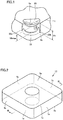
- the present inventors examined a form of damage to a cutting tool in precision machining. Consequently, it was confirmed that various types of wear including crater wear (rake face wear), flank face wear, and boundary wear were caused at a cutting edge of a cutting tool. Such wear will be described below with reference to Fig. 1 .
- Fig. 1 shows a rake face 1a, a flank face 1b, and a cutting edge 1c of a cutting tool.
- a trace of wear 20 like a crater is caused by contact with chips produced from a work material.
- a trace of wear 21 extending in a form of a band is caused by friction with the work material.
- Traces of wear 22a and 22b in a form of spikes are caused at opposing ends of trace of wear 21 in a form of a band.
- Trace of wear 22a defines a lateral boundary portion and trace of wear 22b defines a front boundary portion.
- a characteristic of high resistance against rake face wear tends to lead to a small depth of trace of wear 20, whereas a characteristic of low resistance against rake face wear tends to lead to a large depth of trace of wear 20.
- a width of trace of wear 21 (a distance from an original position of cutting edge 1c to a most distant position) is defined as a maximum flank face wear width Vbmax.
- a characteristic of high resistance against flank face wear tends to lead to small Vbmax, whereas a characteristic of low resistance against flank face wear tends to lead to large Vbmax.
- a width of trace of wear 22b (a distance from an original position of cutting edge 1c to a most distant position) is defined as a boundary wear width Vn.
- a characteristic of high resistance against boundary wear tends to lead to small Vn, whereas a characteristic of low resistance against boundary wear tends to lead to large Vn.
- the present inventors attempted to extend a lifetime of a tool in precision machining by stacking a compound layer excellent in characteristic of resistance against flank face wear and a compound layer excellent in characteristic of resistance against boundary wear.
- the present inventors finished hardened steel by using a surface-coated cutting tool in which a coating was provided on a surface of a substrate composed of a cBN sintered material, the coating being made by alternately stacking fifty TiAlN layers each having a thickness of 12 nm and fifty AlCrN layers each having a thickness around 48 nm.
- a coating was designed because the TiAlN layer was excellent in characteristic of resistance against flank face wear, the AlCrN layer was excellent in characteristic of resistance against boundary wear and hardness, and a super multilayered structure as above was excellent in hardness and toughness.
- a surface-coated cutting tool excellent in balance between a characteristic of resistance against flank face wear and a characteristic of resistance against boundary wear can be obtained. Therefore, the surface-coated cutting tool can have a long lifetime also in precision machining.
- An atomic ratio not particularly identified in a chemical formula such as "AlCrN”, “TiAlN”, or “TiN” herein does not mean that an atomic ratio of each element is set to "1" alone but all conventionally known atomic ratios are encompassed.
- a surface-coated cutting tool 10 (which is also referred to as a "tool 10" below) includes surfaces including an upper surface, a lower surface, and four side surfaces, and as a whole, it is in a shape of a quadrangular prism relatively low in vertical profile.
- Tool 10 is provided with a through hole which extends from the upper surface to the lower surface.
- the upper surface and the lower surface are defined as rake faces 1a and four side surfaces are defined as flank faces 1b.
- the four side surfaces are connected by arc faces and these arc faces are also defined as flank faces 1b.
- a ridgeline defined by an intersection between rake face 1a and flank face 1b and a vicinity of the ridgeline are defined as cutting edge 1c.
- tool 10 includes a substrate 11 including the rake face and the flank face and a coating 12 which covers the surface of substrate 11.
- Coating 12 may cover the entire surface of substrate 11 or a part thereof.
- Coating 12 should be provided at least on the rake face and the flank face which define cutting edge 1c.
- Figs. 2 and 3 show a throwaway tip for turning, a shape and an application of the surface-coated cutting tool according to the present embodiment are not particularly restricted.
- the surface-coated cutting tool include a drill, an end mill, a throwaway tip for drilling, a throwaway tip for end milling, a throwaway tip for milling, a throwaway tip for turning, a metal saw, a gear cutting tool, a reamer, a tap, and a tip for pin milling of a crankshaft.
- FIGs. 2 and 3 show tool 10 with cutting edge 1c in a shape of a sharp edge
- the shape of cutting edge 1c is not limited thereto.
- cutting edge 1c may be in a shape of a negative land.
- Fig. 4 shows a virtual plane A including rake face 1a, a virtual boundary line AA defining a boundary of separation between rake face 1a and virtual plane A, a virtual plane B including flank face 1b, and a virtual boundary line BB defining a boundary of separation between flank face 1b and virtual plane B. In this case, it is the vicinity of virtual boundary line BB in cutting edge 1c that is in contact with a work material.
- the surface-coated cutting tool according to the present embodiment is not limited only to a surface-coated cutting tool constructed as above such that the entire tool includes the substrate and the coating formed on the substrate but also a surface-coated cutting tool constructed such that only a part thereof (in particular, a cutting edge portion) is constructed as above.
- the surface-coated cutting tool according to the present embodiment includes also a surface-coated cutting tool constructed such that only a cutting edge portion of a base (a support) made of cemented carbide is constructed as above. In this case, that cutting edge portion is regarded as a cutting tool in its literal meaning. In other words, even in an example in which the construction above occupies only a part of a cutting tool, that construction is called a surface-coated cutting tool.
- Substrate 11 defines a basic shape of tool 10, and hence it is in a shape matching with a shape of each portion of the substrate (rake face 1a, flank face 1b, and cutting edge 1c).
- Substrate 11 in the present embodiment is made of a cBN sintered material or a ceramic sintered material.
- a cBN sintered material includes a cBN sintered material made of particles composed of cubic boron nitride (which are also referred to as "cBN particles” below) and a binder and a cBN sintered material composed only of cBN particles.
- cBN particles are particularly excellent in hardness.
- the binder serves to bind cBN particles to one another and to compensate for relatively low heat resistance of the cBN particles.
- a content of cBN particles in a cBN sintered material is not particularly restricted and can be determined as appropriate depending on an application of tool 10 and a material for a work material. Too low a content of cBN particles, however, may lead to insufficient characteristics as the cBN sintered material. Therefore, a content of cBN particles in a cBN sintered material is preferably not lower than 30 volume %. An upper limit of the content is not particularly restricted and can be set to 100 volume %. In this case, a hardness is particularly excellent.
- a content of cBN particles in a cBN sintered material can be measured by a method shown below. Initially, a sample including a cross-section of substrate 11 is prepared by cutting any position in tool 10. In preparing a cross-section of substrate 11, a focused ion beam apparatus or a cross-section polisher can be employed. Then, a reflected electron image is obtained by observing a cross-section of a cBN sintered material with a scanning electron microscope (SEM) at a magnification of 2000x. In the reflected electron image, an area where cBN particles are located is observed as a black area and an area where a binder is located is observed as a gray or white area.
- SEM scanning electron microscope
- the reflected electron image is subjected to binary processing with the use of image analysis software to thereby determine an area occupied by cBN particles based on the image subjected to binary processing.
- a content (volume %) of cBN particles in the cBN sintered material can be calculated.
- Volume % of the binder can also be calculated by a similar method.
- TEM transmission electron microscope
- An average particle size (D 50 ) of cBN particles is not particularly restricted either, and it can be, for example, from 0.1 to 10 ⁇ m, preferably from 1 to 5 ⁇ m, and more preferably from 2 to 4 ⁇ m. Normally, a smaller average particle size tends to lead to high strength of a cBN sintered material, and less variation in particle size tends to lead to a homogenous property of the cBN sintered material.
- An average particle size of cBN particles is calculated as below. Initially, a reflected electron image prepared as described above is analyzed by image analysis software to thereby calculate a Heywood diameter of each black area in the reflected electron image. Then, Heywood diameters of at least one hundred cBN particles are calculated by observing at least five fields of view. Then, cumulative distribution is found by arranging Heywood diameters from a minimum value to a maximum value. A particle size at which a cumulative area attains to 50% in the cumulative distribution is defined as D 50 .
- the Heywood diameter means a diameter of a circle equal in measured area to a cBN particle.
- a binder contained in a cBN sintered material is not particularly restricted, and a conventionally known binder can be employed.
- the binder preferably contains at least one compound composed of at least one first element selected from a group consisting of a group 4 element (Ti, Zr, Hf, and the like), a group 5 element (V, Nb, Ta, and the like), and a group 6 element (Cr, Mo, W, and the like) in the periodic table, Al, and Si and at least one second element selected from the group consisting of C, N, O, and B.
- Such compounds include AlCrN, AlN, TiN, CrN, TiCN, NbCN, Al 2 O 3 , AlB 2 , TiB 2 , ZrO 2 , Cr 2 O 3 , and CrB 2 . Since the binder containing such a compound is excellent in adhesiveness to the coating, resistance against peeling of coating 12 in tool 10 can be improved.
- the binder preferably contains at least one of Al compounds composed of Al and at least one element selected from C, N, O, and B.
- Al compounds composed of Al and at least one element selected from C, N, O, and B.
- resistance against peeling of tool 10 can further be improved.
- the Al compound include AlCrN, AlN, Al 2 O 3 , and AlB 2 .
- the binder may contain a compound composed of at least one element of W and Co and at least one element selected from the group consisting of N, B, and O.
- cBN particles are more firmly bonded to one another and hence a hardness of the substrate can be enhanced.
- Specific examples of such a compound include W 3 Co 3 C and W 3 Co 21 B 6 .
- Which compound is contained in the binder can be checked, for example, by qualitatively analyzing a sample prepared as described above (a sample including a cross-section of substrate 11) with an X-ray diffraction (XRD) apparatus.
- a sample prepared as described above a sample including a cross-section of substrate 11
- XRD X-ray diffraction
- a conventionally known ceramic sintered material can be employed as the ceramic sintered material.
- a ceramic sintered material containing any of Al 2 O 3 , ZrO 2 , Si 3 N 4 , and TiC is preferred.
- compound the ceramic sintered material is composed can be checked, for example, by qualitatively analyzing a sample prepared as described above (a sample including a cross-section of substrate 11) with an X-ray diffraction (XRD) apparatus.
- XRD X-ray diffraction
- Coating 12 covers a surface of substrate 11 and thus provides various characteristics such as high heat resistance to tool 10.
- Coating 12 in the present embodiment includes, in particular, an alternating layer made by alternately stacking a first layer and a second layer different in composition from the first layer.
- Coating 12 may include another layer so long as it includes the alternating layer.
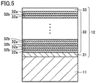
- Fig. 5 shows coating 12 including an underlying layer 31 provided between alternating layer 32 and substrate 11 and a surface layer 33 defining an outermost surface of tool 10. Coating 12 according to the present embodiment will be described below with reference to Fig. 5 .
- Coating 12 can have a thickness, for example, from 0.5 to 20 ⁇ m. When coating 12 is smaller than 0.5 ⁇ m, it is difficult to include desired alternating layer 32 and an effect achieved by alternating layer 32 may not sufficiently be exhibited. Furthermore, coating 12 may insufficiently provide characteristics. When coating 12 is greater than 20 ⁇ m, coating 12 may peel off due to a high pressure applied during cutting. Coating 12 has a thickness preferably from 0.5 to 6 ⁇ m.
- a thickness of coating 12 can be measured as below. Initially, a sample prepared as described above (a sample including a cross-section of substrate 11) is observed with an SEM or a TEM and a magnification is adjusted to include the entire coating in a direction of thickness in an observed image. Then, a thickness of the coating is measured at at least five points and an average value thereof is defined as the thickness of coating 12. A thickness of each layer which will be described in detail below can also be measured by a similar method.
- Alternating layer 32 has a stack structure in which a first layer 32a and a second layer 32b different in composition from first layer 32a are alternately stacked.
- Alternating layer 32 has a thickness preferably from 0.5 to 20 ⁇ m. When the thickness of alternating layer 32 is smaller than 0.5 ⁇ m, an effect attributed to alternating layer 32 may insufficiently be exhibited, and when the thickness exceeds 20 ⁇ m, a crack in a layer in alternating layer 32 may occur and consequently alternating layer 32 may not contribute to improvement in wear resistance.
- Alternating layer 32 has a thickness more preferably from 0.5 to 8 ⁇ m and further preferably from 1 to 5 ⁇ m.
- Alternating layer 32 constituted of first layer 32a and second layer 32b further satisfies each of features (1) to (5) below:
- first layer 32a may contain another element so long as an effect of alternating layer 32 which will be described later is exhibited.
- another element include a metal element such as Ti, Zr, Hf, V, Nb, Ta, Mo, W, and Si and a non-metal element such as C, O, and B.
- first layer 32a is preferably formed from a compound layer mainly composed of Al, Cr, and N among compound layers satisfying the above. This is because it has been found that such a compound layer is particularly excellent in characteristic of resistance against boundary wear and is suitable for exhibiting an effect of alternating layer 32 which will be described later.
- the compound layer mainly composed of Al, Cr, and N means a compound layer in which at least 80 atomic % of the metal element is composed of Al and Cr and at least 80 atomic % of the non-metal element is composed of N.
- first layer 32a is preferably composed of Al, Cr, and N (which is also referred to as an "AlCrN layer” below) and the AlCrN layer is more preferably composed of Al x Cr 1-x N (0.3 ⁇ x ⁇ 0.75).
- second layer 32b may contain another element so long as an effect of alternating layer 32 which will be described later is exhibited.
- another element include a metal element such as Cr, Zr, Hf, V, Nb, Ta, Mo, W, and Si and a non-metal element such as C, O, and B.
- second layer 32b is preferably composed of a compound mainly composed of Ti, Al, and N among the compound layers satisfying the above. This is because it has been found that such a compound layer is particularly excellent in characteristic of resistance against flank face wear and is suitable for exhibiting an effect of alternating layer 32 which will be described later.
- the compound layer mainly composed of Ti, Al, and N means a compound layer in which at least 80 atomic % of the metal element is composed of Ti and Al and at least 80 atomic % of the non-metal element is composed of N.
- second layer 32b is preferably composed of Ti, Al, and N (which is also referred to as a "TiAlN layer” below) and the TiAlN layer is more preferably composed of Ti 1-y Al y N (0.3 ⁇ y ⁇ 0.7).
- the feature (3) means that thickness T1 of first layer 32a is smaller than thickness T2 of second layer 32b.
- Ratio T1/T2 is preferably from 0.1 to 0.9.
- the feature (4) means that one of the number of first layers 32a and the number of second layers 32b in alternating layer 32 is set to at least fifteen and the other thereof is set to at least sixteen.
- the number of interfaces is set preferably to at least fifty.
- the upper limit of the number of interfaces is preferably not greater than 500 from a point of view of a thickness of each layer and the entire thickness (a thickness of alternating layer 32).
- thickness T1 and thickness T2 are each preferably from 1 to 200 nm and more preferably from 5 to 100 nm.
- first layers 32a may be different from one another in thickness, each of them is smaller in thickness than second layer 32b.
- variation in thickness among first layers 32a and among second layers 32b is preferably not higher than 10 %.
- first layer 32a such as the AlCrN layer is made larger in thickness than second layer 32b such as the TiAlN layer in order to extend a lifetime of a tool in precision machining.
- second layer 32b such as the TiAlN layer
- tool 10 essentially requires that thickness T1 of first layer 32a is smaller than thickness T2 of second layer 32b.
- thickness T1 of first layer 32a is smaller than thickness T2 of second layer 32b.
- alternating layer 32 is described in detail above with reference to Fig. 5 , the present inventors further obtained findings from another point of view in completing alternating layer 32. Specifically, the present inventors found that ratio Vn/Vbmax between boundary wear width Vn and maximum flank face wear width Vbmax was from 0.2 to 0.85 (Vbmax was from 30 to 70 ⁇ m) when hardened steel having HRC 60 was cut at a cutting speed from 150 to 200 m/min. with tool 10 including alternating layer 32 which satisfied (1) to (5) above and achieved the effect described above. It can be understood from this fact that the surface-coated cutting tool according to the present embodiment can include a compound layer which satisfies features (6) and (7) below, instead of the alternating layer.
- Vbmax is defined as 30 ⁇ m or greater, because, when it is smaller than 30 ⁇ m, flank face wear may not sufficiently develop, which is not appropriate to evaluate wear characteristics.
- Vbmax is defined as 70 ⁇ m or smaller because wear of the coating is considered as dominant in flank face wear.
- Vn/Vbmax can be considered as being preferably smaller. It is surprising, however, that a lifetime of the tool becomes shorter when Vn/Vbmax is lower than 0.2.
- Vn/Vbmax is more preferably from 0.5 to 0.82.
- a construction of underlying layer 31 is not particularly restricted so long as it has a function to improve adhesiveness between alternating layer 32 and substrate 11, and a conventionally known compound layer can be adopted.
- the underlying layer is preferably similar in composition to any of first layer 32a and second layer 32b which constitute alternating layer 32, because adhesiveness can further be enhanced.
- a thickness of underlying layer 31 is not particularly restricted, and it can be set, for example, to 0.1 to 1 ⁇ m.
- Surface layer 33 can be, for example, a colored layer, because a state of use of a cutting tool can be identified based on a color of the surface.
- the colored layer include a TiB 2 layer and a TiN layer.
- Surface layer 33 may be formed from an AlCrN layer because it can provide lubrication or resistance against deposits.
- a thickness of surface layer 33 is not particularly restricted, and it can be set, for example, to 0.1 to 1 ⁇ m.
- Tool 10 described above can be manufactured, for example, through each step below.
- a substrate is prepared.
- a conventionally known sintering method can be adopted regardless of which of a cBN sintered material and a ceramic sintered material is employed as the substrate.
- the substrate may be arranged at a prescribed position in a base metal which serves as a base for the cutting tool. By brazing the base metal and the substrate to each other, these members may be brought in intimate contact with each other.
- a substrate to be subjected to a step of forming a coating which will be described later may naturally be arranged at a prescribed position in the base metal.
- a coating is then formed on a surface of the substrate.
- the coating can be formed by conventionally known chemical vapor deposition (CVD) or physical vapor deposition (PVD). PVD is a preferred formation method, and in particular, AIP (ion plating in which a solid material is evaporated by using vacuum arc discharge) or sputtering is preferably used.
- CVD chemical vapor deposition
- PVD physical vapor deposition
- AIP ion plating in which a solid material is evaporated by using vacuum arc discharge
- sputtering is preferably used.
- a coating can be formed by using a metal evaporation source containing a metal species which makes up a coating and reaction gas containing a non-metal element which makes up the coating.
- a coating can be formed by using a metal evaporation source, reaction gas, and sputtering gas such as Ar, Kr, or Xe.
- layers are formed by stacking desired layers successively from a side of substrate 11.
- a composition of each layer can be controlled by selecting a metal evaporation source and reaction gas, and a thickness of each layer can be controlled based on a time period for reaction.
- the surface-coated cutting tool according to the present embodiment described in detail above can have a long lifetime also in precision machining.
- surface finish Rz not greater than 3.2 ⁇ m and moreover not greater than 1.6 ⁇ m can be maintained.
- finishing with Rz as above of a work material high in hardness such as hardened steel can be achieved.
- a content of cBN in a substrate was found in accordance with the method described above by using an SEM and image analysis software ("WinROOF” of Mitani Corporation).
- a particle size of cBN particles was measured in accordance with the method described above by using the image analysis software.
- a type of a compound contained in the substrate was identified in accordance with the method described above by using an X-ray diffraction apparatus ("Smart-Lab” manufactured by Rigaku Corporation).
- a thickness of each layer constituting the coating was measured in accordance with the method described above by using an SEM.
- a composition of each layer was identified by using an SEM-EDX apparatus or a TEM-EDX apparatus.
- cBN sintered materials A to H were manufactured by using cBN particles and binders shown in Table 1.
- a compound shown in the field of "X-ray detected compound” in Table 1 refers to a compound detected in qualitative analysis by the X-ray diffraction apparatus.
- the mixture was subjected to heat treatment at 1000°C in vacuum for 30 minutes.
- a compound obtained by heat treatment was uniformly crushed by ball mill crushing.
- a ball medium having a diameter of 6 mm and made of cemented carbide was used for crushing. Source material powders of a binder were thus obtained.
- a ball medium having a diameter of 3 mm and made of boron nitride was used for mixing.
- the obtained mixture was layered on a support substrate made of cemented carbide, and a capsule made of Mo was filled therewith. The capsule was placed in an ultra-high pressure apparatus and sintering was performed at a pressure of 5.5 GPa and a temperature of 1300°C for 30 minutes.
- cBN sintered materials B to H were fabricated by changing as appropriate a type of source material powders of a binder, a particle size of cBN particles, and a ratio of blending of the source material powders and cBN particles as compared with the method of fabricating cBN sintered material A described above.
- cBN sintered material A was shaped into a triangular prism having a thickness of 2 mm and a bottom surface in a shape of an isosceles triangle of which vertical angle was 80° and sides forming the vertical angle therebetween each had a length of 2 mm.
- cBN sintered material A in the shape above was joined to a cutting edge (a corner portion) of a base shaped into CNGA120408 S01225 under the ISO standards and composed of a cemented carbide material (equivalent to K10).
- a brazing material composed of Ti-Zr-Cu was employed for joint.
- a surface-coated cutting tool of each of samples Nos. 1 to 8 was fabricated by forming a coating shown in Table 2 on a surface of the fabricated tool substrate.
- Table 2 shows a thickness of the coating and a composition and a thickness of each layer.
- the table shows a ratio between thickness T1 of the first layer and thickness T2 of the second layer, the number of layers, and the number of interfaces where the first layer and the second layer are in contact with each other.
- a film formation apparatus used for fabricating a coating will initially be described.
- a vacuum pump is connected to the film formation apparatus and the apparatus contains a vacuum chamber in which vacuum can be produced.
- a turntable is placed in the vacuum chamber and constructed such that a tool substrate can be set thereon with a jig being interposed.
- the tool substrate set in the vacuum chamber can be heated by a heater provided in the vacuum chamber.
- a gas pipe for introducing gas for etching and film formation is connected to the vacuum chamber with a mass flow controller for flow rate control being interposed.
- a tungsten filament for generating Ar ions for etching and an arc evaporation source for film formation to which a necessary power supply is connected are arranged in the vacuum chamber.
- a target necessary for film formation is set on the arc evaporation source.
- the tool substrate was set in the vacuum chamber of the film formation apparatus and vacuum was produced in the chamber. Thereafter, the tool substrate was heated to 500°C while the turntable was turned at 3 rpm. Then, Ar gas was introduced into the vacuum chamber, Ar ions were generated by discharging of the tungsten filament, and a bias voltage was applied to the tool substrate. The tool substrate was thus etched by Ar ions. Conditions for etching at this time are shown below.
- An underlying layer was then formed on the tool substrate in the film formation apparatus. Specifically, the underlying layer was fabricated with a time period for vapor deposition being adjusted to form a layer to a thickness of 0.3 ⁇ m under film formation conditions below.
- the alternating layer was then formed on the underlying layer. Specifically, the second layer was fabricated under film formation conditions below.
- the first layer was fabricated under film formation conditions below.
- a thickness of each layer and the total number of layers are different among Nos. 1 to 8, a thickness of each layer was controlled by adjusting the arc discharge current and the number of revolutions of the table within the ranges above, and the total number of layers was controlled by adjusting the number of revolutions of the table and a time period for treatment.
- a TiAlN layer was provided as a lowermost layer of the alternating layer (on a side of the underlying layer) and an AlCrN layer was provided as an uppermost layer thereof.
- Surface-coated cutting tools Nos. 1 to 8 were manufactured as set forth above.
- Ratio Vn/Vbmax between boundary wear width Vn and maximum flank face wear width Vbmax of each surface-coated cutting tool was calculated. Specifically, ratio Vn/Vbmax was calculated by performing cutting under cutting conditions below and measuring Vn (mm) and Vbmax (mm) while Vbmax was within a range from 30 to 70 ⁇ m. Table 3 shows each result.
- Vbmax A smaller value for Vbmax indicates excellent resistance against flank face wear.
- a surface-coated cutting tool of each of samples Nos. 9 to 15 was fabricated by forming a coating shown in Table 4 on a surface of a tool substrate fabricated by a method the same as in Discussion 1 (cBN sintered material B being employed as the substrate).
- Table 4 Substrate Underlying Layer Alternating Layer Surface Layer Coating Composition Thickness ( ⁇ m) Second Layer First Layer The Number of Interfaces Thickness ( ⁇ m) T1/T2 Composition Thickness ( ⁇ m) Thickness ( ⁇ m) Composition T2 (nm) The Number of Layers Composition T1 (nm) The Number of Layers Comparative Example No.
- Each coating was fabricated by using a method and a film formation apparatus the same as those in Discussion 1. Conditions for forming the underlying layer and the alternating layer were similar to those in Discussion 1 except for change in metal element of the target so as to match with the composition of each layer. Surface-coated cutting tools of Nos. 9 to 15 were manufactured as set forth above. Conditions for forming a surface layer are as below.
- Ratio Vn/Vbmax of each surface-coated cutting tool was calculated by performing the method the same as in Discussion 1 under cutting conditions below. Table 5 shows each result.
- Ratio Vn/Vbmax of the surface-coated cutting tool including such an alternating layer was from 0.5 to 0.83, which satisfied the range from 0.2 to 0.85.
- a short tool lifetime of No. 15 is surprising in consideration of particularly excellent hardness of a single layer of AlCrN.
- a surface-coated cutting tool of each of samples Nos. 16 to 21 was fabricated by forming a coating shown in Table 6 on a surface of a tool substrate fabricated by a method the same as in Discussion 1 (cBN sintered material C being employed as the substrate).
- Table 6 Substrate Underlying Layer Alternating Layer Surface Layer Coating Composition Thickess ( ⁇ m) Second Layer First Layer The Number of Interfaces Thickness ( ⁇ m) T1/T2 Composition Thickness ( ⁇ m) Thickness ( ⁇ m) Composition T2 (nm) The Number of Layers Composition T1 (nm) The Number of Layers Comparative Example No.
- Each coating was fabricated by using a method and a film formation apparatus the same as those in Discussion 1. Conditions for forming the underlying layer, the alternating layer, and the surface layer were similar to those in Discussions 1 and 2 except for change in metal element of the target so as to match with the composition of each layer. Surface-coated cutting tools of Nos. 16 to 21 were manufactured as set forth above.
- Ratio Vn/Vbmax of each surface-coated cutting tool was calculated by performing the method the same as in Discussion 1 under cutting conditions below. Table 7 shows each result.
- Ratio Vn/Vbmax of the surface-coated cutting tool including such an alternating layer was from 0.40 to 0.84, which satisfied the range from 0.2 to 0.85.
- a surface-coated cutting tool of each of samples Nos. 22 to 27 was fabricated by forming a coating shown in Table 8 on a surface of a tool substrate fabricated by a method the same as in Discussion 1 (cBN sintered material D being employed as the substrate).
- Table 8 Substrate Underlying Layer Alternating Layer Surface Layer Coating Composition Thickness ( ⁇ m) Second Layer First Layer The Number of Interfaces Thickness ( ⁇ m) T1/T2 Composition Thickness ( ⁇ m) Thickness ( ⁇ m) Composition T2 (nm) The Number of Layers Composition T1 (nm) The Number of Layers Example No.
- Each coating was fabricated by using a method and a film formation apparatus the same as those in Discussion 1. Conditions for forming the underlying layer and the alternating layer were similar to those in Discussion 1 except for change in metal element of the target so as to match with the composition of each layer. Surface-coated cutting tools of Nos. 22 to 27 were manufactured as set forth above.
- Ratio Vn/Vbmax of each surface-coated cutting tool was calculated by performing the method the same as in Discussion 1 under cutting conditions below. Table 9 shows each result.
- Ratio Vn/Vbmax of the surface-coated cutting tool including such an alternating layer was from 0.7 to 0.8, which satisfied the range from 0.2 to 0.85. It was confirmed that the lifetime was longer as the number of interfaces in the alternating layer was greater.
- the alternating layer had a thickness from 0.8 to 11 ⁇ m at this time.
- a surface-coated cutting tool of each of samples Nos. 28 to 35 was fabricated by forming a coating shown in Table 10 on a surface of a tool substrate fabricated by a method the same as in Discussion 1 (cBN sintered materials E to H being employed as the substrate).
- Table 10 Substrate Underlying Layer Alternating Layer Surface Layer Coating Composition Thickness ( ⁇ m) Second Layer First Layer The Number of Interfaces Thickness ( ⁇ m) T1/T2 Composition Thickness ( ⁇ m) Thickness ( ⁇ m) Composition T2 (nm) The Number of Layers Composition T1 (nm) The Number of Layers Example No.
- Each coating was fabricated by using a method and a film formation apparatus the same as those in Discussion 1. Conditions for forming the underlying layer, the alternating layer, and the surface layer were similar to those in Discussions 1 and 2 except for change in metal element of the target so as to match with the composition of each layer. Surface-coated cutting tools of Nos. 28 to 35 were manufactured as set forth above.
- Ratio Vn/Vbmax of each surface-coated cutting tool was calculated by performing the method the same as in Discussion 1 under cutting conditions below. Table 11 shows each result.
Landscapes
- Chemical & Material Sciences (AREA)
- Engineering & Computer Science (AREA)
- Ceramic Engineering (AREA)
- Organic Chemistry (AREA)
- Materials Engineering (AREA)
- Mechanical Engineering (AREA)
- Metallurgy (AREA)
- Chemical Kinetics & Catalysis (AREA)
- Structural Engineering (AREA)
- Inorganic Chemistry (AREA)
- Crystallography & Structural Chemistry (AREA)
- Manufacturing & Machinery (AREA)
- Cutting Tools, Boring Holders, And Turrets (AREA)
Abstract
Description
- The present invention relates to a surface-coated cutting tool. The present application claims priority to Japanese Patent Application No.
2016-199966 filed on October 11, 2016 - A surface-coated cutting tool in which a coating having desired characteristics is provided on a surface of a substrate made of cemented carbide, a ceramic sintered material, or a cubic boron nitride sintered material (which is also referred to as a "cBN sintered material" below) has been developed as a cutting tool.
- For example,
WO2015/064241 (PTL 1) discloses a surface-coated cutting tool in which a coating is provided on a surface of a substrate, the coating including an A layer and a C layer, the A layer being composed of Ti1-xaMaxaC1-yaNya (Ma representing one or more of Cr, Nb, and W and a condition of 0 ≤ xa ≤ 0.7 and 0 ≤ ya ≤ 1 being satisfied), the C layer being composed of Al1-(xc+yc)CrxcMcycN (Mc representing one or more of Ti, V, and Si and a condition of 0.2 ≤ xc ≤ 0.8, 0 ≤ yc ≤ 0.6, and 0.2 ≤ xc+xy ≤ 0.8 being satisfied). According to the surface-coated cutting tool inPTL 1, a flank face wear amount Vb or finished surface roughness Rz of a work material can be reduced owing to a combined effect of a function of suppression of rake face wear and flank face wear attributed to the A layer and a function of suppression of development of boundary wear attributed to the C layer. - For example,
WO2006/070730 (PTL 2) discloses a surface-coated cutting tool in which a coating is provided on a surface of a substrate, the coating including an alternating layer made by alternately stacking an A layer and a B layer, the A layer being composed of a nitride containing Al and Cr, the B layer being composed of a nitride containing Ti and Al. The coating is further configured such that a ratio λA/λB between a thickness λA of the A layer and a thickness λB of the B layer is from 1 to 5 and the A layer is greater in thickness than the B layer. According to the surface-coated cutting tool in PTL 2, flank face wear amount Vb or finished surface roughness Rz can be reduced by alternately stacking the A layer particularly excellent in resistance to oxidation and hardness and the B layer different from the A layer in such characteristics as compressive residual stress or hardness. -
- PTL 1:
WO2015/064241 - PTL 2:
WO2006/070730 - A surface-coated cutting tool according to one manner of the present disclosure includes a substrate including a rake face and a flank face and a coating which covers a surface of the substrate, the substrate being made of a cBN sintered material or a ceramic sintered material, the coating including an alternating layer, the alternating layer being made by alternately stacking a first layer and a second layer different in composition from the first layer, the first layer containing Al, Cr, and N, the second layer containing Ti, Al, and N, a ratio T1/T2 between a thickness T1 of the first layer and a thickness T2 of the second layer being not lower than 0.1 and lower than 1, and there being thirty or more interfaces at which the first layer and the second layer are in contact with each other.
- A surface-coated cutting tool according to one manner of the present disclosure includes a substrate including a rake face and a flank face and a coating which covers a surface of the substrate, the substrate being made of a cBN sintered material or a ceramic sintered material, the coating including a compound layer containing Ti, Al, and N, and the compound layer having a ratio Vn/Vbmax between a boundary wear width Vn and a maximum flank face wear width Vbmax not lower than 0.2 and not higher than 0.85 (Vbmax being not smaller than 30 µm and not greater than 70 µm) when hardened steel having HRC 60 is cut at a cutting speed not lower than 150 m/min. and not higher than 200 m/min.
-
-
Fig. 1 is a partial perspective view showing a form of damage to a cutting edge of a cutting tool in precision machining. -
Fig. 2 is a perspective view showing one example of a surface-coated cutting tool according to one embodiment. -
Fig. 3 is a cross-sectional view along the line III-III inFig. 2 . -
Fig. 4 is a partial cross-sectional view when a cutting edge is honed in the surface-coated cutting tool. -
Fig. 5 is a cross-sectional view schematically showing a construction of a coating according to one embodiment. - High working accuracy has recently been demanded in cutting. For example, in finishing a work material, such precision machining as achieving surface finish Rz of 3.2 µm or 1.6 µm has been demanded. In precision machining, when a work material is a material having a hardness around HRC 40, a cutting tool including a substrate composed of a ceramic sintered material is employed, and when a work material is a very hard material having a hardness around HRC 60, a cutting tool including a substrate composed of a cBN sintered material is employed. A lifetime of a cutting tool used for such an application is determined as having expired at the time point when prescribed surface finish can no longer be maintained. It is actually difficult for a conventional surface-coated cutting tool to maintain a sufficiently long lifetime in such precision machining.
- It is an object of the present disclosure is to provide a surface-coated cutting tool having a long lifetime also in precision machining.
- According to the above, a surface-coated cutting tool having a long lifetime also in precision machining can be provided.
- The present inventors examined a form of damage to a cutting tool in precision machining. Consequently, it was confirmed that various types of wear including crater wear (rake face wear), flank face wear, and boundary wear were caused at a cutting edge of a cutting tool. Such wear will be described below with reference to
Fig. 1 . -
Fig. 1 shows arake face 1a, aflank face 1b, and acutting edge 1c of a cutting tool. Inrake face 1a, a trace ofwear 20 like a crater is caused by contact with chips produced from a work material. Inflank face 1b, a trace ofwear 21 extending in a form of a band is caused by friction with the work material. Traces ofwear wear 21 in a form of a band. Trace ofwear 22a defines a lateral boundary portion and trace ofwear 22b defines a front boundary portion. - A characteristic of high resistance against rake face wear tends to lead to a small depth of trace of
wear 20, whereas a characteristic of low resistance against rake face wear tends to lead to a large depth of trace ofwear 20. A width of trace of wear 21 (a distance from an original position ofcutting edge 1c to a most distant position) is defined as a maximum flank face wear width Vbmax. A characteristic of high resistance against flank face wear tends to lead to small Vbmax, whereas a characteristic of low resistance against flank face wear tends to lead to large Vbmax. A width of trace ofwear 22b (a distance from an original position ofcutting edge 1c to a most distant position) is defined as a boundary wear width Vn. A characteristic of high resistance against boundary wear tends to lead to small Vn, whereas a characteristic of low resistance against boundary wear tends to lead to large Vn. - In general, in order to extend a lifetime of a tool in precision machining, in particular, enhancement of a characteristic of resistance against flank face wear and a characteristic of resistance against boundary wear may be required. This is because, when a characteristic of resistance against flank face wear is low, a cutting resistance increases and consequently undulation is likely in a finished surface (accuracy in working is lowered), and when a characteristic of resistance against boundary wear is low, a shape of boundary wear is transferred to a work material and consequently finished surface roughness is greater.
- The present inventors attempted to extend a lifetime of a tool in precision machining by stacking a compound layer excellent in characteristic of resistance against flank face wear and a compound layer excellent in characteristic of resistance against boundary wear. Specifically, the present inventors finished hardened steel by using a surface-coated cutting tool in which a coating was provided on a surface of a substrate composed of a cBN sintered material, the coating being made by alternately stacking fifty TiAlN layers each having a thickness of 12 nm and fifty AlCrN layers each having a thickness around 48 nm. Such a coating was designed because the TiAlN layer was excellent in characteristic of resistance against flank face wear, the AlCrN layer was excellent in characteristic of resistance against boundary wear and hardness, and a super multilayered structure as above was excellent in hardness and toughness.
- It was difficult, however, to continue to maintain sufficiently small finished surface roughness of a work material with this surface-coated cutting tool, and a demanded lifetime of the tool was not realized. The present inventors further elaborately examined a lifetime of a tool and a form of damage with the number of stacked compound layers and a thickness of each compound layer being intricately varied. Consequently, it was found that expected surface finish was difficult to achieve when a coating having a super multilayered structure was designed based on a characteristic exhibited by each single compound layer alone.
- Then, the present inventors changed their way of thinking, and assumed that, in order to enhance characteristics in particular in connection with surface finish of a coating having a super multilayered structure, it was insufficient simply to enhance a characteristic of resistance against flank face wear and a characteristic of resistance against boundary wear, and balance between these characteristics might be important. The present inventors furthered their studies and found that finishing of hardened steel could successfully be continued by adjusting a construction of a coating for maintaining a ratio Vn/Vbmax between Vn and Vbmax within a prescribed range, and completed the present invention as a result of further studies. An embodiment of the present invention will be listed and described below.
- [1] A surface-coated cutting tool according to one manner of the present invention includes a substrate including a rake face and a flank face and a coating which covers a surface of the substrate, the substrate being made of a cBN sintered material or a ceramic sintered material, the coating including an alternating layer, the alternating layer being made by alternately stacking a first layer and a second layer different in composition from the first layer, the first layer containing Al, Cr, and N, the second layer containing Ti, Al, and N, a ratio T1/T2 between a thickness T1 of the first layer and a thickness T2 of the second layer being not lower than 0.1 and lower than 1, and there being thirty or more interfaces at which the first layer and the second layer are in contact with each other.
According to the manner, a surface-coated cutting tool excellent in balance between a characteristic of resistance against flank face wear and a characteristic of resistance against boundary wear can be obtained. Therefore, the surface-coated cutting tool can have a long lifetime also in precision machining. - [2] In the cutting tool, thickness T1 and thickness T2 are each preferably not smaller than 0.5 nm and not greater than 200 nm. The alternating layer is thus better in balance above.
- [3] In the cutting tool, preferably, the first layer is composed of AlxCr1-xN (0.3 ≤ x ≤ 0.75) and the second layer is composed of Ti1-yAlyN (0.3 ≤ y ≤ 0.7). Thus, while good balance between a characteristic of resistance against flank face wear and a characteristic of resistance against boundary wear is maintained, these characteristics can further be enhanced.
- [4] In the cutting tool, the alternating layer has a thickness preferably not smaller than 0.5 µm and not greater than 20 µm. A longer lifetime can thus be achieved.
- [5] A surface-coated cutting tool according to one manner of the present invention includes a substrate including a rake face and a flank face and a coating which covers a surface of the substrate, the substrate being made of a cBN sintered material or a ceramic sintered material, the coating including a compound layer containing Ti, Al, and N, and the compound layer having a ratio Vn/Vbmax between a boundary wear width Vn and a maximum flank face wear width Vbmax not lower than 0.2 and not higher than 0.85 (Vbmax being not smaller than 30 µm and not greater than 70 µm) when hardened steel having HRC 60 is cut at a cutting speed not lower than 150 m/min. and not higher than 200 m/min.
- According to the manner, a surface-coated cutting tool excellent in balance between a characteristic of resistance against flank face wear and a characteristic of resistance against boundary wear can be obtained. Therefore, the surface-coated cutting tool can have a long lifetime also in precision machining.
- One embodiment of the present invention (hereinafter denoted as the "present embodiment") will be described hereinafter, however, the present embodiment is not limited thereto. In the drawings used for description of the embodiment below, the same or corresponding elements have the same reference characters allotted. An expression in a form "A to B" herein means the upper limit and the lower limit of the range (that is, not less than A and not more than B). When a unit for A is not given and a unit is given only for B, the unit for A and the unit for B are the same. An atomic ratio not particularly identified in a chemical formula such as "AlCrN", "TiAlN", or "TiN" herein does not mean that an atomic ratio of each element is set to "1" alone but all conventionally known atomic ratios are encompassed.
- A surface-coated cutting tool in the present embodiment will be described with reference to
Figs. 2 to 4 . As shown inFig. 2 , a surface-coated cutting tool 10 (which is also referred to as a "tool 10" below) includes surfaces including an upper surface, a lower surface, and four side surfaces, and as a whole, it is in a shape of a quadrangular prism relatively low in vertical profile.Tool 10 is provided with a through hole which extends from the upper surface to the lower surface. Intool 10, the upper surface and the lower surface are defined as rake faces 1a and four side surfaces are defined as flank faces 1b. The four side surfaces are connected by arc faces and these arc faces are also defined as flank faces 1b. A ridgeline defined by an intersection betweenrake face 1a andflank face 1b and a vicinity of the ridgeline are defined as cuttingedge 1c. - As shown in
Fig. 3 ,tool 10 includes asubstrate 11 including the rake face and the flank face and acoating 12 which covers the surface ofsubstrate 11.Coating 12 may cover the entire surface ofsubstrate 11 or a part thereof.Coating 12 should be provided at least on the rake face and the flank face which definecutting edge 1c. - Though
Figs. 2 and3 show a throwaway tip for turning, a shape and an application of the surface-coated cutting tool according to the present embodiment are not particularly restricted. Examples of the surface-coated cutting tool include a drill, an end mill, a throwaway tip for drilling, a throwaway tip for end milling, a throwaway tip for milling, a throwaway tip for turning, a metal saw, a gear cutting tool, a reamer, a tap, and a tip for pin milling of a crankshaft. - Though
Figs. 2 and3 show tool 10 with cuttingedge 1c in a shape of a sharp edge, the shape of cuttingedge 1c is not limited thereto. For example, as shown inFig. 4 , cuttingedge 1c may be in a shape of a negative land.Fig. 4 shows a virtual plane A includingrake face 1a, a virtual boundary line AA defining a boundary of separation betweenrake face 1a and virtual plane A, a virtual plane B includingflank face 1b, and a virtual boundary line BB defining a boundary of separation betweenflank face 1b and virtual plane B. In this case, it is the vicinity of virtual boundary line BB in cuttingedge 1c that is in contact with a work material. - The surface-coated cutting tool according to the present embodiment is not limited only to a surface-coated cutting tool constructed as above such that the entire tool includes the substrate and the coating formed on the substrate but also a surface-coated cutting tool constructed such that only a part thereof (in particular, a cutting edge portion) is constructed as above. For example, the surface-coated cutting tool according to the present embodiment includes also a surface-coated cutting tool constructed such that only a cutting edge portion of a base (a support) made of cemented carbide is constructed as above. In this case, that cutting edge portion is regarded as a cutting tool in its literal meaning. In other words, even in an example in which the construction above occupies only a part of a cutting tool, that construction is called a surface-coated cutting tool.
-
Substrate 11 defines a basic shape oftool 10, and hence it is in a shape matching with a shape of each portion of the substrate (rakeface 1a,flank face 1b, and cuttingedge 1c).Substrate 11 in the present embodiment is made of a cBN sintered material or a ceramic sintered material. - A cBN sintered material includes a cBN sintered material made of particles composed of cubic boron nitride (which are also referred to as "cBN particles" below) and a binder and a cBN sintered material composed only of cBN particles. cBN particles are particularly excellent in hardness. The binder serves to bind cBN particles to one another and to compensate for relatively low heat resistance of the cBN particles.
- A content of cBN particles in a cBN sintered material is not particularly restricted and can be determined as appropriate depending on an application of
tool 10 and a material for a work material. Too low a content of cBN particles, however, may lead to insufficient characteristics as the cBN sintered material. Therefore, a content of cBN particles in a cBN sintered material is preferably not lower than 30 volume %. An upper limit of the content is not particularly restricted and can be set to 100 volume %. In this case, a hardness is particularly excellent. - A content of cBN particles in a cBN sintered material can be measured by a method shown below. Initially, a sample including a cross-section of
substrate 11 is prepared by cutting any position intool 10. In preparing a cross-section ofsubstrate 11, a focused ion beam apparatus or a cross-section polisher can be employed. Then, a reflected electron image is obtained by observing a cross-section of a cBN sintered material with a scanning electron microscope (SEM) at a magnification of 2000x. In the reflected electron image, an area where cBN particles are located is observed as a black area and an area where a binder is located is observed as a gray or white area. - Then, the reflected electron image is subjected to binary processing with the use of image analysis software to thereby determine an area occupied by cBN particles based on the image subjected to binary processing. By substituting the obtained area occupied by cBN particles into an expression below, a content (volume %) of cBN particles in the cBN sintered material can be calculated. Volume % of the binder can also be calculated by a similar method. Alternatively, a transmission electron microscope (TEM) may be used.

- An average particle size (D50) of cBN particles is not particularly restricted either, and it can be, for example, from 0.1 to 10 µm, preferably from 1 to 5 µm, and more preferably from 2 to 4 µm. Normally, a smaller average particle size tends to lead to high strength of a cBN sintered material, and less variation in particle size tends to lead to a homogenous property of the cBN sintered material.
- An average particle size of cBN particles is calculated as below. Initially, a reflected electron image prepared as described above is analyzed by image analysis software to thereby calculate a Heywood diameter of each black area in the reflected electron image. Then, Heywood diameters of at least one hundred cBN particles are calculated by observing at least five fields of view. Then, cumulative distribution is found by arranging Heywood diameters from a minimum value to a maximum value. A particle size at which a cumulative area attains to 50% in the cumulative distribution is defined as D50. The Heywood diameter means a diameter of a circle equal in measured area to a cBN particle.
- A binder contained in a cBN sintered material is not particularly restricted, and a conventionally known binder can be employed. Among others, the binder preferably contains at least one compound composed of at least one first element selected from a group consisting of a group 4 element (Ti, Zr, Hf, and the like), a group 5 element (V, Nb, Ta, and the like), and a group 6 element (Cr, Mo, W, and the like) in the periodic table, Al, and Si and at least one second element selected from the group consisting of C, N, O, and B. Specific examples of such compounds include AlCrN, AlN, TiN, CrN, TiCN, NbCN, Al2O3, AlB2, TiB2, ZrO2, Cr2O3, and CrB2. Since the binder containing such a compound is excellent in adhesiveness to the coating, resistance against peeling of
coating 12 intool 10 can be improved. - Particularly, the binder preferably contains at least one of Al compounds composed of Al and at least one element selected from C, N, O, and B. In this case, resistance against peeling of
tool 10 can further be improved. Specific examples of the Al compound include AlCrN, AlN, Al2O3, and AlB2. - The binder may contain a compound composed of at least one element of W and Co and at least one element selected from the group consisting of N, B, and O. In this case, cBN particles are more firmly bonded to one another and hence a hardness of the substrate can be enhanced. Specific examples of such a compound include W3Co3C and W3Co21B6.
- Which compound is contained in the binder can be checked, for example, by qualitatively analyzing a sample prepared as described above (a sample including a cross-section of substrate 11) with an X-ray diffraction (XRD) apparatus.
- A conventionally known ceramic sintered material can be employed as the ceramic sintered material. Among others, from a point of view of excellent hardness, resistance against heat, and strength, a ceramic sintered material containing any of Al2O3, ZrO2, Si3N4, and TiC is preferred. Of which compound the ceramic sintered material is composed can be checked, for example, by qualitatively analyzing a sample prepared as described above (a sample including a cross-section of substrate 11) with an X-ray diffraction (XRD) apparatus.
-
Coating 12 covers a surface ofsubstrate 11 and thus provides various characteristics such as high heat resistance totool 10.Coating 12 in the present embodiment includes, in particular, an alternating layer made by alternately stacking a first layer and a second layer different in composition from the first layer.Coating 12 may include another layer so long as it includes the alternating layer. For example,Fig. 5 shows coating 12 including anunderlying layer 31 provided between alternatinglayer 32 andsubstrate 11 and a surface layer 33 defining an outermost surface oftool 10.Coating 12 according to the present embodiment will be described below with reference toFig. 5 . -
Coating 12 can have a thickness, for example, from 0.5 to 20 µm. When coating 12 is smaller than 0.5 µm, it is difficult to include desired alternatinglayer 32 and an effect achieved by alternatinglayer 32 may not sufficiently be exhibited. Furthermore, coating 12 may insufficiently provide characteristics. When coating 12 is greater than 20 µm, coating 12 may peel off due to a high pressure applied during cutting.Coating 12 has a thickness preferably from 0.5 to 6 µm. - A thickness of
coating 12 can be measured as below. Initially, a sample prepared as described above (a sample including a cross-section of substrate 11) is observed with an SEM or a TEM and a magnification is adjusted to include the entire coating in a direction of thickness in an observed image. Then, a thickness of the coating is measured at at least five points and an average value thereof is defined as the thickness ofcoating 12. A thickness of each layer which will be described in detail below can also be measured by a similar method. - Alternating
layer 32 has a stack structure in which afirst layer 32a and asecond layer 32b different in composition fromfirst layer 32a are alternately stacked. Alternatinglayer 32 has a thickness preferably from 0.5 to 20 µm. When the thickness of alternatinglayer 32 is smaller than 0.5 µm, an effect attributed to alternatinglayer 32 may insufficiently be exhibited, and when the thickness exceeds 20 µm, a crack in a layer in alternatinglayer 32 may occur and consequently alternatinglayer 32 may not contribute to improvement in wear resistance. Alternatinglayer 32 has a thickness more preferably from 0.5 to 8 µm and further preferably from 1 to 5 µm. - Alternating
layer 32 constituted offirst layer 32a andsecond layer 32b further satisfies each of features (1) to (5) below: - (1)
First layer 32a contains Al, Cr, and N; - (2)
Second layer 32b contains Ti, Al, and N; - (3) a ratio T1/T2 between thickness T1 of
first layer 32a and thickness T2 ofsecond layer 32b is not lower than 0.1 and lower than 1; - (4) There are thirty or more interfaces at which
first layer 32a andsecond layer 32b are in contact with each other; and - (5) Thickness T1 and thickness T2 are each from 0.5 to 200 nm.
- As to the feature (1),
first layer 32a may contain another element so long as an effect of alternatinglayer 32 which will be described later is exhibited. Examples of another element include a metal element such as Ti, Zr, Hf, V, Nb, Ta, Mo, W, and Si and a non-metal element such as C, O, and B. - Among others,
first layer 32a is preferably formed from a compound layer mainly composed of Al, Cr, and N among compound layers satisfying the above. This is because it has been found that such a compound layer is particularly excellent in characteristic of resistance against boundary wear and is suitable for exhibiting an effect of alternatinglayer 32 which will be described later. - The compound layer mainly composed of Al, Cr, and N means a compound layer in which at least 80 atomic % of the metal element is composed of Al and Cr and at least 80 atomic % of the non-metal element is composed of N. In particular,
first layer 32a is preferably composed of Al, Cr, and N (which is also referred to as an "AlCrN layer" below) and the AlCrN layer is more preferably composed of AlxCr1-xN (0.3 ≤ x ≤ 0.75). - As to the feature (2),
second layer 32b may contain another element so long as an effect of alternatinglayer 32 which will be described later is exhibited. Examples of another element include a metal element such as Cr, Zr, Hf, V, Nb, Ta, Mo, W, and Si and a non-metal element such as C, O, and B. - Among others,
second layer 32b is preferably composed of a compound mainly composed of Ti, Al, and N among the compound layers satisfying the above. This is because it has been found that such a compound layer is particularly excellent in characteristic of resistance against flank face wear and is suitable for exhibiting an effect of alternatinglayer 32 which will be described later. - The compound layer mainly composed of Ti, Al, and N means a compound layer in which at least 80 atomic % of the metal element is composed of Ti and Al and at least 80 atomic % of the non-metal element is composed of N. In particular,
second layer 32b is preferably composed of Ti, Al, and N (which is also referred to as a "TiAlN layer" below) and the TiAlN layer is more preferably composed of Ti1-yAlyN (0.3 ≤ y ≤ 0.7). - The feature (3) means that thickness T1 of
first layer 32a is smaller than thickness T2 ofsecond layer 32b. Ratio T1/T2 is preferably from 0.1 to 0.9. - The feature (4) means that one of the number of
first layers 32a and the number ofsecond layers 32b in alternatinglayer 32 is set to at least fifteen and the other thereof is set to at least sixteen. The number of interfaces is set preferably to at least fifty. The upper limit of the number of interfaces is preferably not greater than 500 from a point of view of a thickness of each layer and the entire thickness (a thickness of alternating layer 32). - As to the feature (5), thickness T1 and thickness T2 are each preferably from 1 to 200 nm and more preferably from 5 to 100 nm. Though
first layers 32a may be different from one another in thickness, each of them is smaller in thickness thansecond layer 32b. In view of homogeneity of characteristics of the alternating layer, variation in thickness amongfirst layers 32a and amongsecond layers 32b is preferably not higher than 10 %. - Based on common and general technical knowledge thus far, it is assumed that
first layer 32a such as the AlCrN layer is made larger in thickness thansecond layer 32b such as the TiAlN layer in order to extend a lifetime of a tool in precision machining. This is because, in order to improve surface finish Rz in precision machining and maintain such improved finish, more AlCrN layers higher in hardness and characteristic of resistance against boundary wear than the TiAlN layers excellent in characteristic of resistance against flank face wear are to be arranged for improvement in hardness and characteristic of resistance against boundary wear of the tool. - Surprisingly, however,
tool 10 according to the present embodiment essentially requires that thickness T1 offirst layer 32a is smaller than thickness T2 ofsecond layer 32b. Though a reason therefor is unclear, it may be estimated from various results of studies that a form of damage to a cutting tool, in other words, balance between Vn and Vbmax, improves surface finish Rz owing to interaction between a thickness of each layer and the number of interfaces between the layers and consequently surface finish of a work material can be improved. - Though alternating
layer 32 is described in detail above with reference toFig. 5 , the present inventors further obtained findings from another point of view in completing alternatinglayer 32. Specifically, the present inventors found that ratio Vn/Vbmax between boundary wear width Vn and maximum flank face wear width Vbmax was from 0.2 to 0.85 (Vbmax was from 30 to 70 µm) when hardened steel having HRC 60 was cut at a cutting speed from 150 to 200 m/min. withtool 10 including alternatinglayer 32 which satisfied (1) to (5) above and achieved the effect described above. It can be understood from this fact that the surface-coated cutting tool according to the present embodiment can include a compound layer which satisfies features (6) and (7) below, instead of the alternating layer. -
- (6) The compound layer contains Ti, Al, and N.
- (7) When hardened steel having HRC 60 is cut at a cutting speed from 150 to 200 m/min., ratio Vn/Vbmax between boundary wear width Vn and maximum flank face wear width Vbmax is from 0.2 to 0.85 (Vbmax is from 30 to 70 µm).
- As to the feature (7), Vbmax is defined as 30 µm or greater, because, when it is smaller than 30 µm, flank face wear may not sufficiently develop, which is not appropriate to evaluate wear characteristics. Vbmax is defined as 70 µm or smaller because wear of the coating is considered as dominant in flank face wear. In particular, based on common and general technical knowledge thus far, Vn/Vbmax can be considered as being preferably smaller. It is surprising, however, that a lifetime of the tool becomes shorter when Vn/Vbmax is lower than 0.2. Vn/Vbmax is more preferably from 0.5 to 0.82.
- A construction of
underlying layer 31 is not particularly restricted so long as it has a function to improve adhesiveness between alternatinglayer 32 andsubstrate 11, and a conventionally known compound layer can be adopted. Among others, the underlying layer is preferably similar in composition to any offirst layer 32a andsecond layer 32b which constitute alternatinglayer 32, because adhesiveness can further be enhanced. A thickness ofunderlying layer 31 is not particularly restricted, and it can be set, for example, to 0.1 to 1 µm. - Surface layer 33 can be, for example, a colored layer, because a state of use of a cutting tool can be identified based on a color of the surface. Examples of the colored layer include a TiB2 layer and a TiN layer. Surface layer 33 may be formed from an AlCrN layer because it can provide lubrication or resistance against deposits. A thickness of surface layer 33 is not particularly restricted, and it can be set, for example, to 0.1 to 1 µm.
-
Tool 10 described above can be manufactured, for example, through each step below. - Initially, a substrate is prepared. A conventionally known sintering method can be adopted regardless of which of a cBN sintered material and a ceramic sintered material is employed as the substrate. When the surface-coated cutting tool in the present embodiment occupies only a part of a cutting tool, the substrate may be arranged at a prescribed position in a base metal which serves as a base for the cutting tool. By brazing the base metal and the substrate to each other, these members may be brought in intimate contact with each other. A substrate to be subjected to a step of forming a coating which will be described later may naturally be arranged at a prescribed position in the base metal.
- A coating is then formed on a surface of the substrate. The coating can be formed by conventionally known chemical vapor deposition (CVD) or physical vapor deposition (PVD). PVD is a preferred formation method, and in particular, AIP (ion plating in which a solid material is evaporated by using vacuum arc discharge) or sputtering is preferably used.
- In AIP, a coating can be formed by using a metal evaporation source containing a metal species which makes up a coating and reaction gas containing a non-metal element which makes up the coating. In sputtering, a coating can be formed by using a metal evaporation source, reaction gas, and sputtering gas such as Ar, Kr, or Xe. In any formation method, layers are formed by stacking desired layers successively from a side of
substrate 11. A composition of each layer can be controlled by selecting a metal evaporation source and reaction gas, and a thickness of each layer can be controlled based on a time period for reaction. - The surface-coated cutting tool according to the present embodiment described in detail above can have a long lifetime also in precision machining. For example, surface finish Rz not greater than 3.2 µm and moreover not greater than 1.6 µm can be maintained. For example, when a cBN sintered material is employed as a substrate, finishing with Rz as above of a work material high in hardness such as hardened steel can be achieved.
- Though the present invention will be described hereinafter in further detail with reference to Examples, the present invention is not limited thereto.
- A content of cBN in a substrate was found in accordance with the method described above by using an SEM and image analysis software ("WinROOF" of Mitani Corporation). A particle size of cBN particles was measured in accordance with the method described above by using the image analysis software. A type of a compound contained in the substrate was identified in accordance with the method described above by using an X-ray diffraction apparatus ("Smart-Lab" manufactured by Rigaku Corporation). A thickness of each layer constituting the coating was measured in accordance with the method described above by using an SEM. A composition of each layer was identified by using an SEM-EDX apparatus or a TEM-EDX apparatus.
- cBN sintered materials A to H were manufactured by using cBN particles and binders shown in Table 1. A compound shown in the field of "X-ray detected compound" in Table 1 refers to a compound detected in qualitative analysis by the X-ray diffraction apparatus.
Table 1 Substrate cBN Particles Binder (Source Material Powders) X-Ray Detected Compound Content (Vol %) D50 (µm) A 60 3 TiN0.7, Al cBN, TiN, TiB2, AlN, AlB2 B 75 3 TiN0.7, Al cBN, TiN, TiB2, AlN, AlB2 C 50 2 Ti(CN)0.7, Al, Al2O3 cBN, TiCN, TiB2, AlN, AlB2, Al2O3 D 60 4 Ti(CN)0.7, Al cBN, TiCN, TiB2, AlN, AlB2 E 30 4 TiC0.7, Al cBN, TiC, TiB2, AlN, AlB2 F 80 2 TiN0.7, Al, WC, W3Co3C cBN, TiN, TiB2, AlN, AlB2, WC, W3Cl3C G 60 2 TiN0.7, Al, ZrO2, Al2O3 cBN, TiN, ZrO2, TiB2, AlN, AlB2, Al2O3 H 60 2 Nb(CN)0.7, Al2O3 cBN, NbCN, TiB2, AlN, AlB2, Al2O3 - cBN sintered material A was fabricated as below. Initially, a mixture was obtained by mixing TiN powders (D50 = 1 µm) and Ti powders (D50 = 3 µm) so as to achieve an atomic ratio Ti:N = 1:0.6. The mixture was subjected to heat treatment at 1200°C in vacuum for 30 minutes. Intermetallic compound powders composed of TiN0.7 were obtained by crushing a compound obtained by heat treatment.
- Then, a mixture was obtained by mixing the intermetallic compound powders composed of TiN0.7 and Al powders (D50 = 4 µm) so as to achieve a mass ratio TiN0.7:Al = 9:1. The mixture was subjected to heat treatment at 1000°C in vacuum for 30 minutes. A compound obtained by heat treatment was uniformly crushed by ball mill crushing. A ball medium having a diameter of 6 mm and made of cemented carbide was used for crushing. Source material powders of a binder were thus obtained.
- Then, a powdery mixture was obtained by blending cBN particles (D50 = 3 µm) and the source material powders such that a content of cBN in the cBN sintered material was set to 60 volume % and by uniformly mixing the blend by ball mill mixing. A ball medium having a diameter of 3 mm and made of boron nitride was used for mixing. The obtained mixture was layered on a support substrate made of cemented carbide, and a capsule made of Mo was filled therewith. The capsule was placed in an ultra-high pressure apparatus and sintering was performed at a pressure of 5.5 GPa and a temperature of 1300°C for 30 minutes.
- cBN sintered materials B to H were fabricated by changing as appropriate a type of source material powders of a binder, a particle size of cBN particles, and a ratio of blending of the source material powders and cBN particles as compared with the method of fabricating cBN sintered material A described above.
- cBN sintered material A was shaped into a triangular prism having a thickness of 2 mm and a bottom surface in a shape of an isosceles triangle of which vertical angle was 80° and sides forming the vertical angle therebetween each had a length of 2 mm. cBN sintered material A in the shape above was joined to a cutting edge (a corner portion) of a base shaped into CNGA120408 S01225 under the ISO standards and composed of a cemented carbide material (equivalent to K10). A brazing material composed of Ti-Zr-Cu was employed for joint.
- Then, an outer peripheral surface, an upper surface, and a lower surface of the obtained joined body were ground, and a negative land shape (a width of the negative land being set to 120 µm, an angle of the negative land being set to 25°, and with honing) was formed at the cutting edge. A tool substrate of which cutting edge portion was made of cBN sintered material A was thus fabricated.
- A surface-coated cutting tool of each of samples Nos. 1 to 8 was fabricated by forming a coating shown in Table 2 on a surface of the fabricated tool substrate. Table 2 shows a thickness of the coating and a composition and a thickness of each layer. For the alternating layer, the table shows a ratio between thickness T1 of the first layer and thickness T2 of the second layer, the number of layers, and the number of interfaces where the first layer and the second layer are in contact with each other.
Table 2 Substrate Underlying Layer Alternating Layer Surface Layer Coating Composition Thickness (µm) Second Layer First Layer The Number of Interfaces Thickness (µm) T1/T2 Composition Thickness (µm) Thickness (µm) Composition T2 (nm) The Number of Layers Composition T1 (nm) The Number of Layers Comparative Example No. 1 A Al0.7Cr0.3N 0.3 Ti0.5Al0.5N 4900 1 Al0.7Cr0.3N - 0 0 4.9 - - - 5.2 No. 2 3900 1 1000 1 1 0.26 Example No. 3 190 20 57 20 39 0.30 No. 4 100 38 30 38 75 0.30 No. 5 50 75 15 75 149 0.30 No. 6 25 150 7.5 150 299 0.30 No. 7 10 375 3 375 749 0.30 No. 8 2.7 1400 0.8 1400 2799 0.30 - Each coating was manufactured by cold cathode arc ion plating. A film formation apparatus used for fabricating a coating will initially be described. A vacuum pump is connected to the film formation apparatus and the apparatus contains a vacuum chamber in which vacuum can be produced. A turntable is placed in the vacuum chamber and constructed such that a tool substrate can be set thereon with a jig being interposed. The tool substrate set in the vacuum chamber can be heated by a heater provided in the vacuum chamber. A gas pipe for introducing gas for etching and film formation is connected to the vacuum chamber with a mass flow controller for flow rate control being interposed. In the vacuum chamber, a tungsten filament for generating Ar ions for etching and an arc evaporation source for film formation to which a necessary power supply is connected are arranged in the vacuum chamber. A target necessary for film formation is set on the arc evaporation source.
- The tool substrate was set in the vacuum chamber of the film formation apparatus and vacuum was produced in the chamber. Thereafter, the tool substrate was heated to 500°C while the turntable was turned at 3 rpm. Then, Ar gas was introduced into the vacuum chamber, Ar ions were generated by discharging of the tungsten filament, and a bias voltage was applied to the tool substrate. The tool substrate was thus etched by Ar ions. Conditions for etching at this time are shown below.
- Pressure of Ar gas: 1 Pa
- Substrate bias voltage: -500 V
- An underlying layer was then formed on the tool substrate in the film formation apparatus. Specifically, the underlying layer was fabricated with a time period for vapor deposition being adjusted to form a layer to a thickness of 0.3 µm under film formation conditions below.
- Target: Al (70 atomic %) and Cr (30 atomic %)
- Introduced gas: N2
- Film formation pressure: 4 Pa
- Arc discharge current: 150 A
- Substrate bias voltage: -35 V
- The number of revolutions of table: 3 rpm
- The alternating layer was then formed on the underlying layer. Specifically, the second layer was fabricated under film formation conditions below.
- Target: Ti (50 atomic %) and Al (50 atomic %)
- Introduced gas: N2
- Film formation pressure: 4 Pa
- Arc discharge current: 80 to 250 A
- Substrate bias voltage: -35 V
- The number of revolutions of table: 0.5 to 50 rpm
- The first layer was fabricated under film formation conditions below.
- Target: Al (70 atomic %) and Cr (30 atomic %)
- Introduced gas: N2
- Film formation pressure: 4 Pa
- Arc discharge current: 80 to 250 A
- Substrate bias voltage: -35 V
- The number of revolutions of table: 0.5 to 50 rpm
- Though a thickness of each layer and the total number of layers are different among Nos. 1 to 8, a thickness of each layer was controlled by adjusting the arc discharge current and the number of revolutions of the table within the ranges above, and the total number of layers was controlled by adjusting the number of revolutions of the table and a time period for treatment. In Nos. 2 to 8, a TiAlN layer was provided as a lowermost layer of the alternating layer (on a side of the underlying layer) and an AlCrN layer was provided as an uppermost layer thereof. Surface-coated cutting tools Nos. 1 to 8 were manufactured as set forth above.
- Cutting under cutting conditions below was performed with the use of the surface-coated cutting tools of Nos. 1 to 8. Then, maximum flank face wear width Vbmax (mm) after cutting by 5 km was measured. A cutting distance (km) at the time point when surface finish Rz of a work material attained to 3.2 µm was also measured. Surface roughness Rz refers to a ten point height of roughness profile (Rz) under JIS B 0031: 1994.
-
- Work material: SCM415 round rod (having a hardness of HRC 60)
- Cutting speed: 200 m/min.
- Feed rate: 0.1 mm/rev.
- Depth of cutting: 0.1 mm
- Cutting oil: Used
- Ratio Vn/Vbmax between boundary wear width Vn and maximum flank face wear width Vbmax of each surface-coated cutting tool was calculated. Specifically, ratio Vn/Vbmax was calculated by performing cutting under cutting conditions below and measuring Vn (mm) and Vbmax (mm) while Vbmax was within a range from 30 to 70 µm. Table 3 shows each result.
-
- Work material: SCM415 round rod (having a hardness of HRC 60)
- Cutting speed: 180 m/min.
- Feed rate: 0.1 mm/rev.
- Depth of cutting: 0.1 mm
- Cutting oil: Used
- A smaller value for Vbmax indicates excellent resistance against flank face wear. A longer cutting distance (km) at the time point when surface finish Rz of the work material attained to 3.2 µm indicates a longer lifetime. It was found that, when the alternating layer satisfied the features (1) to (5) above, the surface-coated cutting tool could have a long lifetime as shown in Table 3. Ratio Vn/Vbmax of the surface-coated cutting tool including such an alternating layer was from 0.75 to 0.83, which satisfied the range from 0.2 to 0.85. It was understood that, since the lifetime of Nos. 5 and 6 was particularly long, a long lifetime could not be achieved simply by decreasing Vbmax.
- A surface-coated cutting tool of each of samples Nos. 9 to 15 was fabricated by forming a coating shown in Table 4 on a surface of a tool substrate fabricated by a method the same as in Discussion 1 (cBN sintered material B being employed as the substrate).
Table 4 Substrate Underlying Layer Alternating Layer Surface Layer Coating Composition Thickness (µm) Second Layer First Layer The Number of Interfaces Thickness (µm) T1/T2 Composition Thickness (µm) Thickness (µm) Composition T2 (nm) The Number of Layers Composition T1 (nm) The Number of Layers Comparative Example No. 9 B Al0.7T0.3N 0.5 Ti0.3Al0.7N 3000 1 Al0.6Cr0.4N - 0 0 3 - Al0.5Cr0.5N 0.3 3.8 Example No. 10 57 50 3 50 99 0.05 No. 11 50 50 10 50 99 0.20 No. 12 45 50 15 50 99 0.33 No. 13 40 50 20 50 99 0.50 No. 14 32 50 28 50 99 0.88 Comparative Example No. 15 12 50 48 50 99 4.0 - Each coating was fabricated by using a method and a film formation apparatus the same as those in
Discussion 1. Conditions for forming the underlying layer and the alternating layer were similar to those inDiscussion 1 except for change in metal element of the target so as to match with the composition of each layer. Surface-coated cutting tools of Nos. 9 to 15 were manufactured as set forth above. Conditions for forming a surface layer are as below. -
- Target: Al (50 atomic %) and Cr (50 atomic %)
- Introduced gas: N2
- Film formation pressure: 4 Pa
- Arc discharge current: 150 A
- Substrate bias voltage: -50 V
- The number of revolutions of table: 2 rpm
- Cutting under cutting conditions below was performed with the use of the surface-coated cutting tools of Nos. 9 to 15. Vbmax (mm) and a cutting distance (km) were calculated by a method the same as in
Discussion 1. Table 5 shows each result. -
- Work material: SCM415 round rod (having a hardness of HRC 60)
- Cutting speed: 150 m/min.
- Feed rate: 0.1 mm/rev.
- Depth of cutting: 0.1 mm
- Cutting oil: Used
- Ratio Vn/Vbmax of each surface-coated cutting tool was calculated by performing the method the same as in
Discussion 1 under cutting conditions below.
Table 5 shows each result. -
- Work material: SCM415 round rod (having a hardness of HRC 60)
- Cutting speed: 160 m/min.
- Feed rate: 0.1 mm/rev.
- Depth of cutting: 0.1 mm
- Cutting oil: Used
- As shown in Table 5, it was found that the surface-coated cutting tool could have a long lifetime when the alternating layer satisfied the features (1) to (5) above. Ratio Vn/Vbmax of the surface-coated cutting tool including such an alternating layer was from 0.5 to 0.83, which satisfied the range from 0.2 to 0.85. A short tool lifetime of No. 15 is surprising in consideration of particularly excellent hardness of a single layer of AlCrN.
- A surface-coated cutting tool of each of samples Nos. 16 to 21 was fabricated by forming a coating shown in Table 6 on a surface of a tool substrate fabricated by a method the same as in Discussion 1 (cBN sintered material C being employed as the substrate).
Table 6 Substrate Underlying Layer Alternating Layer Surface Layer Coating Composition Thickess (µm) Second Layer First Layer The Number of Interfaces Thickness (µm) T1/T2 Composition Thickness (µm) Thickness (µm) Composition T2 (nm) The Number of Layers Composition T1 (nm) The Number of Layers Comparative Example No. 16 C Ti0.5AI0.5N 0.2 Ti0.7Al0.3N 4000 1 - - 0 0 4.0 - TiN 0.7 4.9 Example No. 17 200 16 Al0.75Cr0.25N 50 16 31 4.0 0.25 4.9 No. 18 200 16 Ti0.2Al0.4Cr0.4N 40 16 31 3.8 0.20 4.7 No. 19 200 16 Al0.5Cr0.4V0.1N 70 16 31 4.3 0.35 5.2 No. 20 Ti0.45Al0.5Si0.05C0.1N0.9 200 16 Al0.5Cr0.45Si0.05C0.1N0.9 70 16 31 4.3 0.35 5.2 No. 21 Ti0.3Al0.6Nb0.1N 200 16 Al0.5Cr0.5N 70 16 31 4.3 0.35 5.2 - Each coating was fabricated by using a method and a film formation apparatus the same as those in
Discussion 1. Conditions for forming the underlying layer, the alternating layer, and the surface layer were similar to those inDiscussions 1 and 2 except for change in metal element of the target so as to match with the composition of each layer. Surface-coated cutting tools of Nos. 16 to 21 were manufactured as set forth above. - Cutting under cutting conditions below was performed with the use of the surface-coated cutting tools of Nos. 16 to 21. Vbmax (mm) and a cutting distance (km) were calculated by a method the same as in
Discussion 1. Table 7 shows each result. -
- Work material: SCM415 round rod (having a hardness of HRC 60)
- Cutting speed: 100 m/min.
- Feed rate: 0.1 mm/rev.
- Depth of cutting: 0.1 mm
- Cutting oil: Used
- Ratio Vn/Vbmax of each surface-coated cutting tool was calculated by performing the method the same as in
Discussion 1 under cutting conditions below.
Table 7 shows each result. -
- Work material: SCM415 round rod (having a hardness of HRC 60)
- Cutting speed: 150 m/min.
- Feed rate: 0.1 mm/rev.
- Depth of cutting: 0.1 mm
- Cutting oil: Used
- As shown in Table 7, it was found that the surface-coated cutting tool could have a long lifetime when the alternating layer satisfied the features (1) to (5) above. Ratio Vn/Vbmax of the surface-coated cutting tool including such an alternating layer was from 0.40 to 0.84, which satisfied the range from 0.2 to 0.85.
- A surface-coated cutting tool of each of samples Nos. 22 to 27 was fabricated by forming a coating shown in Table 8 on a surface of a tool substrate fabricated by a method the same as in Discussion 1 (cBN sintered material D being employed as the substrate).
Table 8 Substrate Underlying Layer Alternating Layer Surface Layer Coating Composition Thickness (µm) Second Layer First Layer The Number of Interfaces Thickness (µm) T1/T2 Composition Thickness (µm) Thickness (µm) Composition T2 (nm) The Number of Layers Composition T1 (nm) The Number of Layers Example No. 22 D Al0.5Cr0.5N 0.3 Ti0.8Al0.1Ta0.1N 30 245 Al0.4Cr0.4Nb0.2N 15 245 489 11.0 0.50 - - 11.3 No. 23 175 175 349 7.9 8.2 No. 24 135 135 269 6.1 6.4 No. 25 90 90 179 4.1 4.4 No. 26 45 45 89 2.0 2.3 No. 27 18 18 35 0.8 1.1 - Each coating was fabricated by using a method and a film formation apparatus the same as those in
Discussion 1. Conditions for forming the underlying layer and the alternating layer were similar to those inDiscussion 1 except for change in metal element of the target so as to match with the composition of each layer. Surface-coated cutting tools of Nos. 22 to 27 were manufactured as set forth above. - Cutting under cutting conditions below was performed with the use of the surface-coated cutting tools of Nos. 22 to 27. Vbmax (mm) and a cutting distance (km) were calculated by a method the same as in
Discussion 1. Table 9 shows each result. -
- Work material: SCM415 round rod (having a hardness of HRC 58)
- Cutting speed: 100 m/min.
- Feed rate: 0.1 mm/rev.
- Depth of cutting: 0.15 mm
- Cutting oil: Used
- Ratio Vn/Vbmax of each surface-coated cutting tool was calculated by performing the method the same as in
Discussion 1 under cutting conditions below.
Table 9 shows each result. -
- Work material: SCM415 round rod (having a hardness of HRC 58)
- Cutting speed: 150 m/min.
- Feed rate: 0.1 mm/rev.
- Depth of cutting: 0.15 mm
- Cutting oil: Used
- As shown in Table 9, it was found that the surface-coated cutting tool could have a long lifetime when the alternating layer satisfied the features (1) to (5) above.
- Ratio Vn/Vbmax of the surface-coated cutting tool including such an alternating layer was from 0.7 to 0.8, which satisfied the range from 0.2 to 0.85. It was confirmed that the lifetime was longer as the number of interfaces in the alternating layer was greater. The alternating layer had a thickness from 0.8 to 11 µm at this time.
- A surface-coated cutting tool of each of samples Nos. 28 to 35 was fabricated by forming a coating shown in Table 10 on a surface of a tool substrate fabricated by a method the same as in Discussion 1 (cBN sintered materials E to H being employed as the substrate).
Table 10 Substrate Underlying Layer Alternating Layer Surface Layer Coating Composition Thickness (µm) Second Layer First Layer The Number of Interfaces Thickness (µm) T1/T2 Composition Thickness (µm) Thickness (µm) Composition T2 (nm) The Number of Layers Composition T1 (nm) The Number of Layers Example No. 28 E Al0.7Cr0.3N 0.5 Ti0.4Al0.6N 70 30 Al0.6Cr0.4N 20 30 59 2.7 0.29 TiN 0.3 3.5 Comparative Example No. 29 Ti0.5Al0.5N 2200 1 - - 0 0 - - - 3.2 Example No. 30 F Ti0.4Al0.6N 70 30 Al0.6Cr0.4N 20 30 59 0.29 TiN 0.3 3.5 Comparative Example No. 31 Ti0.5Al0.5N 2200 1 - - 0 0 - - - 3.2 Example No. 32 G Ti0.4Al0.6N 70 30 Al0.6Cr0.4N 20 30 59 0.29 TiN 0.3 3.5 Comparative Example No. 33 Ti0.5Al0.5N 2200 1 - - 0 0 - - - 3.2 Example No. 34 H Ti0.4Al0.6N 70 30 Al0.6Cr0.4N 20 30 59 0.29 TiN 0.3 3.5 Comparative Example No. 35 Ti0.5Al0.5N 2200 1 - - 0 0 - - - 3.2 - Each coating was fabricated by using a method and a film formation apparatus the same as those in
Discussion 1. Conditions for forming the underlying layer, the alternating layer, and the surface layer were similar to those inDiscussions 1 and 2 except for change in metal element of the target so as to match with the composition of each layer. Surface-coated cutting tools of Nos. 28 to 35 were manufactured as set forth above. - Cutting under cutting conditions below was performed with the use of the surface-coated cutting tools of Nos. 28 to 35. Vbmax (mm) and a cutting distance (km) were calculated by a method the same as in
Discussion 1. Table 11 shows each result. -
- Work material: SCM415 round rod (having HRC 58)
- Cutting speed: 200 m/min.
- Feed rate: 0.1 mm/rev.
- Depth of cutting: 0.1 mm
- Cutting oil: None
- Ratio Vn/Vbmax of each surface-coated cutting tool was calculated by performing the method the same as in
Discussion 1 under cutting conditions below.
Table 11 shows each result. -
- Work material: SCM415 round rod (having a hardness of HRC 58)
- Cutting speed: 200 m/min.
- Feed rate: 0.1 mm/rev.
- Depth of cutting: 0.1 mm
- Cutting oil: Used
- As shown in Table 11, it was found that the surface-coated cutting tool could have a long lifetime when the alternating layer satisfied the features (1) to (5) above. Ratio Vn/Vbmax of the surface-coated cutting tool including such an alternating layer was 0.79.
- It should be understood that the embodiment disclosed herein is illustrative and non-restrictive in every respect. The scope of the present invention is defined by the terms of the claims rather than the embodiment above and is intended to include any modifications within the scope and meaning equivalent to the terms of the claims.
- 1a rake face; 1b flank face; 1c cutting edge; 10 surface-coated cutting tool; 11 substrate; 12 coating; 20 crater wear; 21 flank face wear; 22a, 22b boundary wear; 31 underlying layer; 32 alternating layer; 32a first layer; 32b second layer
| Vbmax (µm) | km | Vn/Vbmax | ||
| Comparative Example | No. 1 | 32 | 3.3 | 0.91 |
| No. 2 | 32 | 3.3 | 0.86 | |
| Example | No. 3 | 33 | 4.8 | 0.80 |
| No. 4 | 33 | 5.9 | 0.77 | |
| No. 5 | 34 | 8.1 | 0.75 | |
| No. 6 | 38 | 7.1 | 0.76 | |
| No. 7 | 41 | 5.6 | 0.80 | |
| No. 8 | 50 | 4.1 | 0.83 | |
| Vbmax (µm) | km | Vn/Vbmax | ||
| Comparative Example | No. 9 | 42 | 2.8 | 0.91 |
| Example | No. 10 | 43 | 4.0 | 0.83 |
| No. 11 | 45 | 4.6 | 0.72 | |
| No. 12 | 46 | 5.2 | 0.65 | |
| No. 13 | 48 | 5.9 | 0.57 | |
| No. 14 | 52 | 6.3 | 0.50 | |
| Comparative Example | No. 15 | 92 | 2.0 | 0.15 |
| Vbmax (µm) | km | Vn/Vbmax | ||
| Comparative Example | No. 16 | 38 | 2.6 | 0.90 |
| Example | No. 17 | 41 | 4.1 | 0.84 |
| No. 18 | 39 | 5.2 | 0.80 | |
| No. 19 | 44 | 5.3 | 0.75 | |
| No. 20 | 42 | 4.9 | 0.60 | |
| No. 21 | 40 | 5.1 | 0.40 | |
| Vbmax (µm) | km | Vn/Vbmax | ||
| Example | No. 22 | 40 | 7.2 | 0.70 |
| No. 23 | 47 | 6.1 | 0.71 | |
| No. 24 | 55 | 5.3 | 0.72 | |
| No. 25 | 64 | 4.9 | 0.73 | |
| No. 26 | 67 | 4.5 | 0.75 | |
| No. 27 | 70 | 4.1 | 0.80 | |
| Vbmax (µm) | km | Vn/Vbmax | ||
| Example | No. 28 | 50 | 4.8 | 0.79 |
| Comparative Example | No. 29 | 41 | 3.6 | 0.89 |
| Example | No. 30 | 70 | 5.2 | 0.79 |
| Comparative Example | No. 31 | 62 | 3.9 | 0.89 |
| Example | No. 32 | 67 | 5.1 | 0.79 |
| Comparative Example | No. 33 | 56 | 3.7 | 0.89 |
| Example | No. 34 | 64 | 4.9 | 0.79 |
| Comparative Example | No. 35 | 53 | 3.5 | 0.89 |
Claims (5)
- A surface-coated cutting tool including a substrate including a rake face and a flank face and a coating which covers a surface of the substrate,
the substrate being made of a cubic boron nitride sintered material or a ceramic sintered material,
the coating including an alternating layer,
the alternating layer being made by alternately stacking a first layer and a second layer different in composition from the first layer,
the first layer containing Al, Cr, and N,
the second layer containing Ti, Al, and N,
a ratio T1/T2 between a thickness T1 of the first layer and a thickness T2 of the second layer being not lower than 0.1 and lower than 1, and
there being thirty or more interfaces at which the first layer and the second layer are in contact with each other. - The surface-coated cutting tool according to claim 1, wherein
the thickness T1 and the thickness T2 are each not smaller than 0.5 nm and not greater than 200 nm. - The surface-coated cutting tool according to claim 1 or 2, wherein
the first layer is composed of AlxCr1-xN (0.3 ≤ x ≤ 0.75), and
the second layer is composed of Ti1-yAlyN (0.3 ≤ y ≤ 0.7). - The surface-coated cutting tool according to any one of claims 1 to 3,
wherein
the alternating layer has a thickness not smaller than 0.5 µm and not greater than 20 µm. - A surface-coated cutting tool including a substrate including a rake face and a flank face and a coating which covers a surface of the substrate,
the substrate being made of a cubic boron nitride sintered material or a ceramic sintered material,
the coating including a compound layer containing Ti, Al, and N, and
the compound layer having a ratio Vn/Vbmax between a boundary wear width Vn and a maximum flank face wear width Vbmax not lower than 0.2 and not higher than 0.85 (Vbmax being not smaller than 30 µm and not greater than 70 µm) when hardened steel having HRC 60 is cut at a cutting speed not lower than 150 m/min. and not higher than 200 m/min.
Applications Claiming Priority (2)
| Application Number | Priority Date | Filing Date | Title |
|---|---|---|---|
| JP2016199966 | 2016-10-11 | ||
| PCT/JP2017/033962 WO2018070195A1 (en) | 2016-10-11 | 2017-09-20 | Surface-coated cutting tool |
Publications (2)
| Publication Number | Publication Date |
|---|---|
| EP3527309A1 true EP3527309A1 (en) | 2019-08-21 |
| EP3527309A4 EP3527309A4 (en) | 2020-05-20 |
Family
ID=61906235
Family Applications (1)
| Application Number | Title | Priority Date | Filing Date |
|---|---|---|---|
| EP17860696.8A Withdrawn EP3527309A4 (en) | 2016-10-11 | 2017-09-20 | Surface-coated cutting tool |
Country Status (3)
| Country | Link |
|---|---|
| US (1) | US20200055790A1 (en) |
| EP (1) | EP3527309A4 (en) |
| WO (1) | WO2018070195A1 (en) |
Families Citing this family (6)
| Publication number | Priority date | Publication date | Assignee | Title |
|---|---|---|---|---|
| DE102019113117B4 (en) * | 2019-05-17 | 2023-12-28 | voestalpine eifeler Vacotec GmbH | Method for producing a cold forming tool and cold forming tool |
| EP3991888B1 (en) * | 2019-10-10 | 2023-09-06 | Sumitomo Electric Hardmetal Corp. | Cutting tool |
| DE112021001910T5 (en) * | 2020-03-27 | 2023-01-12 | Kyocera Corporation | COATED TOOL AND CUTTING TOOL |
| JP7486713B2 (en) * | 2020-12-21 | 2024-05-20 | 株式会社Moldino | Coated Tools |
| JP7507887B2 (en) * | 2020-12-25 | 2024-06-28 | 京セラ株式会社 | Coated and cutting tools |
| EP4459008A1 (en) * | 2023-05-02 | 2024-11-06 | Voestalpine Eifeler Vacotec Gmbh | Workpiece having a hard material coating |
Family Cites Families (7)
| Publication number | Priority date | Publication date | Assignee | Title |
|---|---|---|---|---|
| EP1842610B1 (en) * | 2004-12-28 | 2017-05-03 | Sumitomo Electric Hardmetal Corp. | Surface-coated cutting tool and process for producing the same |
| JP4970886B2 (en) * | 2006-03-24 | 2012-07-11 | 住友電気工業株式会社 | Surface coated cutting tool |
| JP5027491B2 (en) * | 2006-12-06 | 2012-09-19 | 住友電気工業株式会社 | Surface coated cutting tool |
| JP5382581B2 (en) * | 2009-07-01 | 2014-01-08 | 住友電工ハードメタル株式会社 | Surface coated cutting tool |
| WO2014002948A1 (en) * | 2012-06-29 | 2014-01-03 | 住友電工ハードメタル株式会社 | Cutting tool for surface coating |
| JP6102653B2 (en) * | 2013-09-19 | 2017-03-29 | 三菱マテリアル株式会社 | Surface coated cutting tool |
| JP2017159424A (en) * | 2016-03-11 | 2017-09-14 | 三菱マテリアル株式会社 | Surface coated cutting tool with excellent chipping and wear resistance |
-
2017
- 2017-09-20 US US16/341,374 patent/US20200055790A1/en not_active Abandoned
- 2017-09-20 EP EP17860696.8A patent/EP3527309A4/en not_active Withdrawn
- 2017-09-20 WO PCT/JP2017/033962 patent/WO2018070195A1/en not_active Ceased
Also Published As
| Publication number | Publication date |
|---|---|
| EP3527309A4 (en) | 2020-05-20 |
| US20200055790A1 (en) | 2020-02-20 |
| WO2018070195A1 (en) | 2018-04-19 |
Similar Documents
| Publication | Publication Date | Title |
|---|---|---|
| US20200055790A1 (en) | Surface-Coated Cutting Tool | |
| EP3444053A1 (en) | Surface-coated cutting tool and manufacturing method therefor | |
| WO2014163081A1 (en) | Surface-coated cutting tool | |
| JP2006198735A (en) | Surface coated cermet cutting tool whose hard coating layer exhibits excellent chipping resistance in high-speed intermittent cutting | |
| EP3950190B1 (en) | Cutting tool | |
| EP3412386B1 (en) | Surface-coated cutting tool and manufacturing method therefor | |
| KR102269461B1 (en) | Surface-coated boron nitride sintered tool | |
| EP3552741B1 (en) | Surface coated cutting tool | |
| EP4494788B1 (en) | Cutting tool | |
| EP3960341A1 (en) | Cutting tool | |
| JP2021126738A (en) | Surface coating cutting tool that demonstrates excellent chipping resistance and wear resistance in strong intermittent cutting | |
| WO2017175400A1 (en) | Surface-coated cutting tool and method for producing same | |
| JP7380978B1 (en) | Cutting tools | |
| WO2016148056A1 (en) | Surface-coated cutting tool with rigid coating layers exhibiting excellent chipping resistance | |
| KR20240026951A (en) | cutting tools | |
| CN118524901A (en) | Cutting Tools | |
| JP2016221672A (en) | Surface coated cutting tool with excellent chipping resistance due to hard coating layer | |
| JP7021607B2 (en) | Surface-coated cutting tools with excellent chipping resistance and chipping resistance due to the hard coating layer | |
| JP2021030356A (en) | Surface-coated cutting tool | |
| JP2008178943A (en) | Surface coated cutting tool whose hard coating layer exhibits excellent wear resistance in intermittent high feed cutting | |
| JP4716250B2 (en) | Surface-coated cermet cutting tool that exhibits excellent chipping resistance with a hard coating layer in high-speed heavy cutting | |
| JP7338827B1 (en) | Cutting tools | |
| JP7453616B2 (en) | surface coated cutting tools | |
| KR20190032454A (en) | Cutting tool and manufacturing method thereof | |
| WO2017038840A1 (en) | Surface-coated cutting tool having rigid coating layer exhibiting excellent chipping resistance |
Legal Events
| Date | Code | Title | Description |
|---|---|---|---|
| PUAI | Public reference made under article 153(3) epc to a published international application that has entered the european phase |
Free format text: ORIGINAL CODE: 0009012 |
|
| 17P | Request for examination filed |
Effective date: 20190409 |
|
| AK | Designated contracting states |
Kind code of ref document: A1 Designated state(s): AL AT BE BG CH CY CZ DE DK EE ES FI FR GB GR HR HU IE IS IT LI LT LU LV MC MK MT NL NO PL PT RO RS SE SI SK SM TR |
|
| AX | Request for extension of the european patent |
Extension state: BA ME |
|
| DAV | Request for validation of the european patent (deleted) | ||
| DAX | Request for extension of the european patent (deleted) | ||
| A4 | Supplementary search report drawn up and despatched |
Effective date: 20200421 |
|
| RIC1 | Information provided on ipc code assigned before grant |
Ipc: C23C 16/34 20060101ALI20200415BHEP Ipc: B23D 77/00 20060101ALI20200415BHEP Ipc: B23B 27/14 20060101AFI20200415BHEP Ipc: B23C 5/16 20060101ALI20200415BHEP Ipc: C04B 41/89 20060101ALI20200415BHEP Ipc: B23G 5/06 20060101ALI20200415BHEP Ipc: B23B 51/00 20060101ALI20200415BHEP Ipc: B23F 21/00 20060101ALI20200415BHEP Ipc: C23C 14/06 20060101ALI20200415BHEP |
|
| 17Q | First examination report despatched |
Effective date: 20201022 |
|
| STAA | Information on the status of an ep patent application or granted ep patent |
Free format text: STATUS: THE APPLICATION HAS BEEN WITHDRAWN |
|
| 18W | Application withdrawn |
Effective date: 20201222 |