EP3527061B1 - Landwirtschaftliche erntemaschine - Google Patents
Landwirtschaftliche erntemaschine Download PDFInfo
- Publication number
- EP3527061B1 EP3527061B1 EP18208575.3A EP18208575A EP3527061B1 EP 3527061 B1 EP3527061 B1 EP 3527061B1 EP 18208575 A EP18208575 A EP 18208575A EP 3527061 B1 EP3527061 B1 EP 3527061B1
- Authority
- EP
- European Patent Office
- Prior art keywords
- baffle plate
- hood
- covering hood
- working rotor
- agricultural harvester
- Prior art date
- Legal status (The legal status is an assumption and is not a legal conclusion. Google has not performed a legal analysis and makes no representation as to the accuracy of the status listed.)
- Not-in-force
Links
Images
Classifications
-
- A—HUMAN NECESSITIES
- A01—AGRICULTURE; FORESTRY; ANIMAL HUSBANDRY; HUNTING; TRAPPING; FISHING
- A01D—HARVESTING; MOWING
- A01D43/00—Mowers combined with apparatus performing additional operations while mowing
- A01D43/10—Mowers combined with apparatus performing additional operations while mowing with means for crushing or bruising the mown crop
-
- A—HUMAN NECESSITIES
- A01—AGRICULTURE; FORESTRY; ANIMAL HUSBANDRY; HUNTING; TRAPPING; FISHING
- A01D—HARVESTING; MOWING
- A01D34/00—Mowers; Mowing apparatus of harvesters
- A01D34/01—Mowers; Mowing apparatus of harvesters characterised by features relating to the type of cutting apparatus
- A01D34/412—Mowers; Mowing apparatus of harvesters characterised by features relating to the type of cutting apparatus having rotating cutters
- A01D34/63—Mowers; Mowing apparatus of harvesters characterised by features relating to the type of cutting apparatus having rotating cutters having cutters rotating about a vertical axis
- A01D34/81—Casings; Housings
Definitions
- the present invention relates to an agricultural harvesting machine with a rotationally drivable working rotor for processing stalk-shaped and / or leaf-shaped crops, the working rotor being assigned a cover on the circumference, which delimits a discharge area of the working rotor and / or delimits a conveying channel between the working rotor and the cover .
- the crop is thrown from the peripheral side by the working rotor, which usually rotates at a higher speed, whereby the working rotors are usually enclosed or covered by a cover, on the one hand to control the flying around of the crop, on the other hand but also to form a protective barrier in front of the working rotor and to prevent injuries.
- the cover hood can form a guide plate in the discharge area of the working rotor which, for example, extends tangentially to the crop flow at least in sections and can direct it in a desired direction.
- the cover hood can also interact with the working rotor in order to process the crop in the desired manner, in particular to have a conditioning and opening effect, for example as it is provided by a processor.
- the crop thrown against the cover can be further opened up by the mechanical impact effect in order to dry more quickly, but this can also be achieved, for example, by the fact that the cover forms a conveying channel between itself and the working rotor through which the harvest is forced.
- such covers should be as light as possible in order not to unnecessarily impair the weight of the machine. Since such covering hoods are usually large-area components, an attempt is usually made to provide the thinnest possible construction, for example by means of a thin sheet of metal.
- the cover must not only be dimensionally stable enough to fulfill the desired baffle function for the harvested crop and, if necessary, have the desired opening or conditioning effect, but also have sufficient strength to withstand stone chips.
- the crop regularly contains impurities such as clods of earth or stones, which are thrown against the cover hood by the working rotor with a correspondingly high level of energy, so that the cover hood is exposed to high stresses and deformations at certain points.
- the font GB 645 098 A shows a conditioner whose hood surrounding the rotor is provided on the inside with a wavy line-shaped contoured rubber coating in order to process the crop more intensively.
- the font WO 01/03494 A1 shows a mower with a downstream conditioner to which an adjustable, arched guide member is assigned within a surrounding housing.
- the font FR 27 38 450 shows a lawnmower, the rotating blades of which are surrounded by a bell-shaped cover, on the inner peripheral wall of which a thermoplastic wear protection is provided.
- the present invention is based on the object of creating an improved agricultural harvesting machine of the type mentioned, which avoids the disadvantages of the prior art and further develops the latter in an advantageous manner.
- a very lightweight cover should be created which, despite its low weight, avoids flaking paint due to the formation of dents and the corresponding susceptibility to rust.
- a stone chip barrier on the inside of the cover, which cushions impacting stone chips, so that at least on the outside of the cover no dents or dents occur. Even if damage occurs on the inside of the cover at the rockfall barrier provided there, the outside of the cover remains undamaged and at least largely free of deformation, so that any paint applied there no longer flakes off.
- a baffle plate is provided on an inner side of the covering hood facing the working rotor to protect the covering hood against falling stones from the working rotor.
- Such a baffle plate on the inner circumferential wall of the cover absorbs the impact energy from striking stones or other foreign bodies at least to the extent that the cover itself or its outside does not experience any significant deformation, so that the cover can be made thin-walled in order to achieve an overall low weight.
- such a baffle plate can be attached over the entire surface in the manner of a coating to the inner wall.
- Said baffle plate can form, so to speak, a second skin and / or a doubled inner layer of the covering hood, which, unlike a lacquer layer applied on the inside, has a significantly greater material thickness and energy absorption capacity.
- the cover hood is nonetheless painted on the inside so that the baffle plate is applied to the paint on the inside of the cover plate.
- a coating in the cover plate which is also provided on the inner circumference and which is so to speak under the baffle plate, can also cause corrosion of the cover hood the inside can be prevented.
- the baffle plate can be glued flat or partially to the inside of the cover hood, for example.
- the baffle plate can also be fastened to the cover hood in a different way, for example by screwing or riveting or by other form-fitting fastening means such as clamping claws or snap-in plugs.
- the baffle plate does not have to be attached to the entire surface of the inside of the cover, but can be blinded in the manner of an inner shell in front of the inside of the cover and together with the cover form a double-walled hood structure.
- the cover plate can be spaced apart from the cover hood by an air gap, for example by spacers between the inside of the cover hood and the outside of the baffle plate.
- Such an arrangement of the baffle plate spaced apart in the form of a gap enables mechanical stresses and the impact energy of stone chips or the like to be kept away from the cover hood in a particularly efficient manner.
- the baffle plate on the one hand and the cover hood on the other hand consist of different materials, of plastic on the one hand and a metal material on the other hand.
- the cover hood can be formed from sheet metal in a manner known per se and optionally painted, while the baffle plate is made of plastic.
- the baffle plate In order to let thrown crops slide off easily and to prevent sticky crops that may be slightly damp and sticky from sticking on, the baffle plate has a low sliding friction, smooth and with a small roughness depth provided surface, wherein advantageously a thermoplastic with a friction-reducing additive is used.
- the baffle plate can advantageously be manufactured at least in sections from a sintered plastic based on polyethylene.
- a sintered plastic based on polyethylene have high impact strength, at the same time excellent sliding properties and also have a noise-insulating effect.
- a high molecular weight, in particular ultra high molecular weight, low-pressure polyethylene can be used or sintered in order to form the baffle plate.
- the sintered polyethylene-based plastic can be alloyed with molybdenum disulfide, the proportion of this additive being selected in the range from 0.1 percent by weight to 20 percent by weight, in particular about 1 percent by weight to 10 percent by weight can be.
- the plastic of the baffle plate is advantageously selected and / or alloyed and / or sintered in such a way that the notched impact strength of the plastic plate is in the range of 90-200, in particular about 100-160 kJ / m 2 .
- the notched impact strength mentioned can be determined, for example, according to the DIN EN ISO 179-2 measuring method.
- the plastic of the baffle plate can be configured, ie selected and / or alloyed and / or sintered, in such a way that the Shore hardness of the baffle plate, for example measured according to DIN EN ISO 868, 15 S, is in the range of 50-70, in particular about 60- 67 Shore.
- a plastic configured in this way has, on the one hand, sufficient strength, in particular notched impact strength. On the other hand, it has a strong noise-insulating effect, in order to significantly dampen the noise generated by falling rocks acoustically.
- the baffle plate covers two thirds or more of the cover.
- the baffle plate can advantageously have a curved and / or polygonal kinked contouring and / or form a free-form surface that extends around the working rotor, in particular around the circumference and, for example, can be arranged at least in sections tangential to the ejection direction of the working rotor.
- the cover plate can at least substantially correspond to or follow the contouring of the cover hood, the impact plate not having to depict the entire cover hood in terms of shape, but rather can only extend in an area of the cover hood at risk of falling rocks.
- the said baffle plate can be provided on the cover of a crop processor, such a crop processor can have, for example, a rotatably drivable tine rotor, which can be driven around a horizontal axis of rotation, in particular transversely to the direction of travel.
- a cover hood and / or the baffle plate can have a uniaxially curved contouring in the manner of an extruded profile and / or extend circumferentially over the working rotor in the manner of a curved channel.
- Such a conditioner can in particular be used together with a mower and / or be designed as a mower-conditioner combination.
- the cover hood mentioned, together with the baffle plate provided on the inside, can also be used on a pure mower, in particular cover its rear discharge area, if a mowing function without an additional conditioner effect is desired.
- the agricultural harvesting machine can comprise a mower 2, which can for example comprise a plurality of cutting rotors arranged next to one another, which can be driven about upright axes and can have cutting blades on the circumferential side on a bottom section.
- the mower unit 2 can also have other cutting tools, for example in the form of a cutter bar.
- a conditioner rotor 1 can be arranged downstream of the mower unit 2 in the direction of travel, which can be driven around a horizontal axis of rotation which can extend transversely to the direction of travel, such a conditioner rotor, for example, having a substantially cylindrical rotor body 3, from the circumference of which conditioner tines 4 protrude can.
- conditioner rotors configured or contoured differently can also be used, such as those per se from the scriptures EP 26 33 749 A1 are known, to the extent that, ie the training of the conditioner rotor is referred to.
- the conditioner rotor 1 can be surrounded or covered on the circumferential side by a cover 6, wherein said cover 2 can extend in particular above and / or behind the cover rotor.
- the mentioned cover 2 extends at least in a discharge area 7 in which the working rotor 1 discharges harvested material as intended.
- the cover 6 can extend in this case at least in a sector that extends behind and / or above the working rotor 1 in the direction of travel.
- the harvesting machine 5 can in particular be an attachment that can be attached to a tractor, although in principle self-propelled harvesting machines can also be considered, for example in the form of self-propelled mowers.
- the mentioned direction of travel is in Fig. 1 marked with the reference number 8.
- the cover 6 can in particular be curved and / or beveled like a polygonal profile around the working rotor 1 and / or nestle along the circumferential side of the working rotor, in particular in the discharge area 7 form a baffle extending tangentially to the discharge direction.
- the cover 7 can be designed in the manner of a channel or a uniaxially curved extruded profile.
- Said cover 6 can be made from sheet metal, for example.
- baffle plate 9 On the inside of the cover 6, which faces the working rotor 1, a baffle plate 9 is provided, which protects the actual cover 6 from stone chips and can form an inside facing of the cover.
- the said baffle plate can be attached to the inner wall of the covering hood 6 in the manner of a coating over the entire surface.
- the baffle plate 9 can also be blinded in front of the inside of the covering hood in the manner of an inner shell in order to form a double-walled hood structure together with the covering hood.
- an air gap can be provided between the baffle plate 9 and the cover 6.
- the baffle plate has a Comprises a full area resting on the cover section and a further section spaced from the baffle plate by an air gap.
- the baffle plate 9 can imitate the cover 6 in terms of shape and / or essentially correspond in its shape to the cover or a substantial portion thereof.
- the aforementioned statements on the contouring or shaping of the cover hood also apply analogously to the baffle plate.
- Said baffle plate 9 can be fastened to the cover 6 in various ways, whereby in particular a form-fitting and / or force-fitting fastening, for example by a screw connection with several screw bolts, can be provided.
- a detachable fastening of the baffle plate 9 on the cover 6 can be provided in order to be able to replace the baffle plate 9 when worn.
- Said baffle plate 9 is made of a plastic, in particular a sintered plastic based on polyethylene. Such a material is known, for example, under the brand name Robalon.
Landscapes
- Life Sciences & Earth Sciences (AREA)
- Environmental Sciences (AREA)
- Soil Working Implements (AREA)
- Harvester Elements (AREA)
Description
- Die vorliegende Erfindung betrifft eine landwirtschaftliche Erntemaschine mit einem rotatorisch antreibbaren Arbeitsrotor zum Bearbeiten von halm- und/oder blattförmigem Erntegut, wobei dem Arbeitsrotor umfangsseitig eine Abdeckhaube zugeordnet ist, die einen Abwurfbereich des Arbeitsrotors begrenzt und/oder einen Förderkanal zwischen dem Arbeitsrotor und der Abdeckhaube begrenzt.
- Bei landwirtschaftlichen Erntemaschinen wie Mähmaschinen und Aufbereitern oder Konditionierern wird das Erntegut vom Arbeitsrotor, der üblicherweise mit höherer Drehzahl umläuft, von der Umfangsseite abgeworfen, wobei die Arbeitsrotoren üblicherweise von einer Abdeckhaube umschlossen bzw. abgedeckt sind, um einerseits das Umherfliegen des Ernteguts zu kontrollieren, andererseits aber auch eine Schutzbarriere vor dem Arbeitsrotor zu bilden und Verletzungen zu verhindern.
- Die Abdeckhaube kann dabei im Abwurfbereich des Arbeitsrotors ein Leitblech bilden, das sich beispielsweise zumindest abschnittsweise tangential zum Erntegutstrom erstrecken und diesen in eine gewünschte Richtung lenken kann. Andererseits kann die Abdeckhaube aber auch mit dem Arbeitsrotor zusammenwirken, um das Erntegut in der gewünschten Weise zu bearbeiten, insbesondere um beispielsweise eine Konditionier- und Aufschließwirkung zu erzielen, wie sie von einem Aufbereiter bereitgestellt wird. Insbesondere kann das gegen die Abdeckhaube geworfene Erntegut durch die mechanische Aufprallwirkung weiter aufgeschlossen werden, um rascher zu trocknen, wobei dies beispielsweise aber auch dadurch erzielt werden kann, dass die Abdeckhaube zwischen sich und dem Arbeitsrotor einen Förderkanal bildet, durch den das Erntegut hindurchgezwungen wird.
- Einerseits sollen solche Abdeckhauben möglichst leicht bauen, um das Maschinengewicht nicht unnötig zu beeinträchtigen. Da es sich bei solchen Abdeckhauben üblicherweise um großflächige Bauteile handelt, wird in der Regel versucht, eine möglichst dünnwandige Ausbildung beispielsweise durch ein dünnes Metallblech vorzusehen. Andererseits muss die Abdeckhaube aber nicht nur ausreichend formstabil sein, um für das angeworfene Erntegut die gewünschte Leitblechfunktion zu erfüllen und ggf. die gewünschte Aufschließ- bzw. Konditionierwirkung zu haben, sondern auch eine ausreichende Festigkeit besitzen, um Steinschlägen zu widerstehen. Leider sind im Erntegut regelmäßig Verunreinigungen wie Erdklumpen oder Steine enthalten, die vom Arbeitsrotor mit entsprechend hoher Energie gegen die Abdeckhaube geschleudert werden, so dass die Abdeckhaube punktuell hohen Belastungen ausgesetzt ist und Verformungen erleidet.
- Dabei ist weniger ein tatsächliches Reißen oder Brechen der Abdeckhaube das Problem, zumindest wenn ein Metallblech mit ausreichender Wandstärke verwendet wird. Allerdings kommt es zu Verbeulungen oder Dellen, an denen die Lackierung des Metallblechs bricht oder aufplatzt, was in der Folge zu Korrosionsschäden an der Abdeckhaube führt. Um dies zu verhindern, wurden zwar schon verschiedene Maßnahmen angedacht, die jedoch bislang allesamt im Ergebnis unbefriedigend sind. Werden dickere oder hochfeste Metallbleche für die Abdeckhaube verwendet, steigt deren Gewicht oder auch deren Preis übermäßig an, wobei sich bei hochfesten Metallblechen zudem auch die Problematik ergibt, dass die Bleche schwierig in die stark konturierte Haubenform zu bringen sind, ohne zu reißen. Andere Maßnahmen wie beispielsweise eine elastische Mehrschichtlackierung, wie sie aus dem Automobilbereich bekannt sind, sind den Beanspruchungen solcher Erntemaschinen nicht gewachsen und darüber hinaus auch sehr kostenintensiv.
- Aus der Schrift
DE 201 15 919 U1 ist eine Mähmaschine mit einem nachgeordneten Aufbereiter bekannt, dessen Aufbereiterrotor von einer Abdeckhaube umfangsseitig abgedeckt wird. Bei diesem Aufbereiter sind zwar die Zinken des Aufbereiterrotors im Bereich ihrer Schlagkanten mit einer Armierung aus hochfestem Werkstoff gegen Steinschläge geschützt, die Abdeckhaube leider allerdings an den zuvor geschilderten Problemen. Ein weiteres Beispiel für einen gattungsgemäßen Aufbereiter, der einer Mähmaschine nachgeschaltet ist, zeigt die SchriftEP 26 33 749 A1 . - Ferner zeigen die Schriften
EP 24 85 574 B1 undEP 24 85 577 B1 eine landwirtschaftliche Maschine mit einem Kompressionswalzengehäuse, wobei vorgeschlagen wird, das Gehäuse mehrteilig auszubilden, um Verschleißteile einfacher austauschen zu können. Die genannte Steinschlagproblematik löst die genannte Schrift allerdings nicht, zumal die Gehäuseteile nur schwierig zu demontieren sind. - Die Schrift
GB 645 098 A WO 01/03494 A1 FR 27 38 450 - Der vorliegenden Erfindung liegt hiervon ausgehend die Aufgabe zugrunde, eine verbesserte landwirtschaftliche Erntemaschine der genannten Art zu schaffen, die Nachteile des Standes Technik vermeidet und Letzteren in vorteilhafter Weise weiterbildet. Insbesondere soll eine sehr leicht bauende Abdeckhaube geschaffen werden, die trotz ihres geringen Gewichts Lackabplatzungen infolge Beulenbildung und entsprechende Rostanfälligkeit vermeidet.
- Erfindungsgemäß wird die genannte Aufgabe durch eine landwirtschaftliche Erntemaschine gemäß Anspruch 1 gelöst. Bevorzugte Ausgestaltungen der Erfindung sind Gegenstand der abhängigen Ansprüche.
- Es wird also vorgeschlagen, an der Innenseite der Abdeckhaube eine Steinschlagbarriere vorzublenden, die auftreffende Steinschläge abfedert, so dass zumindest an der Außenseite der Abdeckhaube keine Beulen- und Dellenbildung eintritt. Auch wenn an der Innenseite der Abdeckhaube an der dort vorgesehenen Steinschlagbarriere Beschädigungen auftreten, bleibt die Außenseite der Abdeckhaube doch unbeschädigt und zumindest weitgehend verformungsfrei, so dass ein dort ggf. aufgebrachter Lack nicht länger abplatzt. Erfindungsgemäß ist an einer dem Arbeitsrotor zugewandten Innenseite der Abdeckhaube eine Prallplatte zum Schutz der Abdeckhaube gegen Steinschlag vom Arbeitsrotor her vorgesehen. Eine solche Prallplatte an der Innenumfangswandung der Abdeckhaube schluckt die Aufprallenergie von anschlagenden Steinen oder anderen Fremdkörpern zumindest insoweit, dass die Abdeckhaube selbst bzw. deren Außenseite keine wesentlichen Verformungen erfährt, so dass die Abdeckhaube dünnwandig ausgebildet sein kann, um ein insgesamt geringes Gewicht zu erzielen.
- In Weiterbildung der Erfindung kann eine solche Prallplatte vollflächig aufliegend nach Art einer Beschichtung an der Innenwandung angebracht sein. Die genannte Prallplatte kann sozusagen eine zweite Haut und/oder eine aufgedoppelte Innenschicht der Abdeckhaube bilden, die anders als eine innenseitig aufgebrachte Lackschicht eine deutlich größere Materialstärke und Energieaufnahmefähigkeit besitzt.
- Ist die Prallplatte in der genannten Weise vollflächig nach Art einer Beschichtung auf der Innenseite der Abdeckhaube angebracht, ist die Abdeckhaube nichtsdestotrotz innenseitig lackiert, so dass die Prallplatte auf der innenumfangsseitigen Lackierung der Abdeckplatte aufgebracht ist. Durch eine solche auch innenumfangsseitig vorgesehene Lackierung im Abdeckblech, die sozusagen unter der Prallplatte liegt, kann Korrosion der Abdeckhaube auch von der Innenseite her verhindert werden.
- Bei der genannten vollflächigen Anbringung kann die Prallplatte beispielsweise flächig oder partiell an der Innenseite der Abdeckhaube verklebt sein. Alternativ oder zusätzlich kann die Prallplatte aber auch in anderer Weise an der Abdeckhaube befestigt sein, beispielsweise durch Anschrauben oder Annieten oder durch andere formschlüssige Befestigungsmittel wie beispielsweise Klemmpratzen oder Raststecker.
- In alternativer Weiterbildung der Erfindung muss die Prallplatte aber nicht vollflächig anliegend an der Innenseite der Abdeckhaube angebracht sein, sondern kann nach Art einer Innenschale vor die Innenseite der Abdeckhaube geblendet sein und zusammen mit der Abdeckhaube eine doppelwandige Haubenstruktur bilden. Beispielsweise kann die Abdeckplatte von der Abdeckhaube durch einen Luftspalt beabstandet sein, beispielsweise durch Distanzstücke zwischen der Innenseite der Abdeckhaube und der Außenseite der Prallplatte. Durch eine solche spaltförmig beabstandete Anordnung der Prallplatte können mechanische Beanspruchungen und die Aufschlagenergie von Steinschlag oder dergleichen besonders effizient von der Abdeckhaube weggehalten werden.
- Gemäß der Erfindung bestehen die Prallplatte einerseits und die Abdeckhaube andererseits aus unterschiedlichen Werkstoffen, aus Kunststoff einerseits und einem Metallwerkstoff andererseits. Insbesondere kann die Abdeckhaube in an sich per se bekannter Weise aus einem Metallblech geformt und ggf. lackiert sein, während die Prallplatte aus Kunststoff gefertigt ist.
- Um angeworfenes Erntegut leicht abgleiten zu lassen und ein Anbacken von ggf. auch leicht feuchtem, klebrigem Erntegut zu verhindern, besitzt die Prallplatte eine gleitreibungsarme, glatte und mit einer geringen Rauhtiefe versehene Oberfläche, wobei vorteilhafterweise ein thermoplastischer Kunststoff mit einem reibungsreduzierenden Zusatz verwendet wird.
- Vorteilhafterweise kann die Prallplatte zumindest abschnittsweise aus einem gesinterten Kunststoff auf Polyethylenbasis gefertigt sein. Solche gesinterten Kunststoffe auf Polyethylenbasis besitzen eine hohe Schlagzähigkeit, gleichzeitig ausgezeichnete Gleiteigenschaften und wirken überdies lärmdämmend. Insbesondere kann ein hochmolekulares, insbesondere ultrahochmolekulares Niederdruckpolyethylen verwendet bzw. gesintert werden, um die Prallplatte zu bilden.
- Um die Gleitreibung besonders niedrig zu halten, gleichzeitig aber gute Verschleißeigenschaften zu erzielen, kann der gesinterte Kunststoff auf Polyethylenbasis mit Molybdändisulfid legiert sein, wobei der Anteil dieses Zusatzstoffes im Bereich von 0,1 Gewichtsprozent bis 20 Gewichtsprozent, insbesondere etwa 1 Gewichtsprozent bis 10 Gewichtsprozent gewählt sein kann.
- Vorteilhafterweise wird der Kunststoff der Prallplatte derart ausgewählt und/oder legiert und/oder gesintert, dass die Kerbschlagzähigkeit der Kunststoffplatte im Bereich von 90-200, insbesondere etwa 100-160 kJ/m2 beträgt. Die genannte Kerbschlagzähigkeit kann beispielsweise nach dem DIN EN ISO 179-2 Messverfahren bestimmt sein. Alternativ oder zusätzlich kann der Kunststoff der Prallplatte derart konfiguriert, d.h. ausgewählt und/oder legiert und/oder gesintert sein, dass die Shorehärte der Prallplatte, beispielsweise gemessen nach DIN EN ISO 868, 15 S im Bereich von 50-70, insbesondere etwa 60-67 Shore beträgt.
- Ein solchermaßen konfigurierter Kunststoff besitzt einerseits die ausreichende Festigkeit, insbesondere Kerbschlagzähigkeit. Andererseits wirkt er stark lärmdämmend, um die Geräuschbildung bei Steinschlag akustisch signifikant zu dämpfen.
- Die Prallplatte überdeckt zwei Drittel oder mehr der Abdeckhaube.
- Die Prallplatte kann vorteilhafterweise eine gebogene und/oder polygonzugartig abgeknickte Konturierung besitzen und/oder eine Freiformfläche bilden, die sich um den Arbeitsrotor insbesondere umfangsseitig herum erstreckt und beispielsweise zumindest abschnittsweise tangential zur Abwurfrichtung des Arbeitsrotors angeordnet sein kann.
- Die Abdeckplatte kann zumindest im Wesentlichen der Konturierung der Abdeckhaube entsprechen bzw. dieser folgen, wobei die Prallplatte nicht die gesamte Abdeckhaube formenmäßig abbilden muss, sondern sich nur in einem steinschlaggefährdeten Bereich der Abdeckhaube erstrecken kann.
- In vorteilhafter Weiterbildung der Erfindung kann die genannte Prallplatte an der Abdeckhaube eines Erntegut-Aufbereiters vorgesehen sein, wobei ein solcher Erntegutaufbereiter beispielsweise einen rotatorisch antreibbaren Zinkenrotor aufweisen kann, der beispielsweise um eine liegende Rotationsachse insbesondere quer zur Fahrtrichtung angetrieben sein kann. Die Abdeckhaube und/oder die Prallplatte können bei einem solchen Aufbereiterrotor eine einachsig gebogene Konturierung nach Art eines Strangpressprofils besitzen und/oder sich nach Art einer gebogenen Rinne umfangsseitig über dem Arbeitsrotor erstrecken.
- Ein solcher Aufbereiter kann insbesondere zusammen mit einer Mähmaschine Verwendung finden und/oder als Mähwerks-Aufbereiter-Kombination ausgebildet sein.
- Die genannte Abdeckhaube zusammen mit der innenseitig vorgesehenen Prallplatte kann aber auch an einem reinen Mähwerk Verwendung finden, insbesondere dessen heckseitigem Auswurfbereich abdecken, wenn eine Mähfunktion ohne zusätzliche Aufbereiterwirkung erwünscht ist.
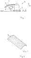
- Die Erfindung wird nachfolgend anhand eines bevorzugten Ausführungsbeispiels und zugehöriger Zeichnungen näher erläutert. In den Zeichnungen zeigen:
- Fig. 1:
- eine schematische Seitenansicht einer landwirtschaftlichen Erntemaschine in Form einer Mähmaschinen-Aufbereiter-Kombination nach einer vorteilhaften Ausführung der Erfindung, bei der ein Aufbereiterrotor dem Mähwerksaggregat nachgeordnet und durch eine Abdeckhaube abgedeckt ist, und
- Fig. 2:
- eine perspektivische Draufsicht auf die Prallplatte, die der Abdeckhaube des Aufbereiters innenumfangsseitig vorgeblendet ist.
- Wie
Fig. 1 zeigt, kann die landwirtschaftliche Erntemaschine ein Mähwerk 2 umfassen, das beispielsweise eine Mehrzahl nebeneinander angeordneter Schneidrotoren umfassen kann, die um aufrechte Achsen antreibbar sein und an einem bodenseitigen Abschnitt umfangsseitig Schneidmesser aufweisen können. Grundsätzlich kann die Mähwerkseinheit 2 aber auch andere Schneidwerkzeuge beispielsweise in Form eines Messerbalkens aufweisen. - Der Mähwerkseinheit 2 in Fahrtrichtung nachgeordnet kann ein Aufbereiterrotor 1 sein, der um eine liegende Rotationsachse, die sich quer zur Fahrtrichtung erstrecken kann, angetrieben werden kann, wobei ein solcher Aufbereiterrotor beispielsweise einen im Wesentlichen zylindrischen Rotorkorpus 3 besitzen kann, von dessen Umfang Aufbereiterzinken 4 vorstehen können. Grundsätzlich können aber auch anders konfigurierte bzw. konturierte Aufbereiterrotoren Verwendung finden, so wie sie beispielsweise per se aus der Schrift
EP 26 33 749 A1 bekannt sind, auf die insoweit, d.h. die Ausbildung des Aufbereiterrotors Bezug genommen wird. - Wie
Fig. 1 zeigt, kann der Aufbereiterrotor 1 umfangsseitig von einer Abdeckhaube 6 umgeben bzw. abgedeckt sein, wobei sich die genannte Abdeckhaube 2 insbesondere oberhalb und/oder hinter dem Abdeckrotor erstrecken kann. Vorteilhafterweise erstreckt sich die genannte Abdeckhaube 2 zumindest in einem Abwurfbereich 7, in dem der Arbeitsrotor 1 bestimmungsgemäß Erntegut abwirft. Die Abdeckhaube 6 kann sich hierbei zumindest in einem Sektor erstrecken, der sich in Fahrtrichtung hinter und/oder über dem Arbeitsrotor 1 erstreckt. Soweit auf die Fahrtrichtung der Erntemaschine 5 Bezug genommen wird, sei darauf hingewiesen, dass die Erntemaschine 5 insbesondere ein Anbaugerät sein kann, das an einen Schlepper anbaubar ist, wobei grundsätzlich aber auch selbstfahrende Erntemaschinen in Betracht kommen, beispielsweise in Form von selbstfahrenden Mähern. Die genannte Fahrtrichtung ist inFig. 1 mit der Bezugsziffer 8 gekennzeichnet. - Die Abdeckhaube 6 kann insbesondere bogenförmig und/oder abgekantet nach Art eines Polygonzugprofils um den Arbeitsrotor 1 herum konturiert sein und/oder sich entlang der Umfangsseite des Arbeitsrotors anschmiegen, insbesondere im Abwurfbereich 7 ein sich tangential zur Abwurfrichtung erstreckendes Leitblech bilden.
- Beispielsweise kann die Abdeckhaube 7 nach Art einer Rinne oder eines einachsig gebogenen Strangpressprofils ausgebildet sein.
- Die genannte Abdeckhaube 6 kann hierbei beispielsweise aus einem Metallblech gefertigt sein.
- Auf der Innenseite der Abdeckhaube 6, die dem Arbeitsrotor 1 zugewandt ist, ist eine Prallplatte 9 vorgesehen, die die eigentliche Abdeckhaube 6 vor Steinschlägen schützt und eine innenseitige Verblendung der Abdeckhaube bilden kann.
- Wie eingangs schon erläutert, kann die genannte Prallplatte vollflächig aufliegend nach Art einer Beschichtung an der Innenwandung der Abdeckhaube 6 angebracht sein. Alternativ kann die Prallplatte 9 auch nach Art einer Innenschale vor die Innenseite der Abdeckhaube geblendet sein, um zusammen mit der Abdeckhaube eine doppelwandige Haubenstruktur zu bilden. Beispielsweise kann ein Luftspalt zwischen Prallplatte 9 und Abdeckhaube 6 vorgesehen sein. Es sind auch Mischformen möglich, beispielsweise dahingehend, dass die Prallplatte einen vollflächig an der Abdeckhaube anliegenden Abschnitt und einen weiteren, von der Prallplatte durch einen Luftspalt beabstandeten Abschnitt umfasst.
- Die Prallplatte 9 kann die Abdeckhaube 6 formenmäßig nachbilden und/oder in ihrer Form im Wesentlichen der Abdeckhaube oder einem wesentlichen Abschnitt hiervon entsprechen. Insofern gelten die vorgenannten Ausführungen zur Konturierung bzw. Formgebung der Abdeckhaube analog auch für die Prallplatte.
- Die genannte Prallplatte 9 kann an der Abdeckhaube 6 in verschiedener Weise befestigt sein, wobei insbesondere eine formschlüssige und/oder kraftschlüssige Befestigung, beispielsweise durch eine Verschraubung mit mehreren Schraubbolzen vorgesehen sein kann.
- Vorteilhafterweise kann eine lösbare Befestigung der Prallplatte 9 an der Abdeckhaube 6 vorgesehen sein, um die Prallplatte 9 bei Verschleiß austauschen zu können.
- Die genannte Prallplatte 9 ist aus einem Kunststoff gefertigt, insbesondere aus einem gesinterten Kunststoff auf Polyethylenbasis. Ein solcher Werkstoff ist beispielsweise unter dem Markennamen Robalon bekannt.
Claims (10)
- Landwirtschaftliche Erntemaschine mit einem rotatorisch antreibbaren Arbeitsrotor (1) zum Bearbeiten von halm- und/oder blattförmigem Erntegut, wobei dem Arbeitsrotor (1) umfangsseitig eine Abdeckhaube (6) aus einem Metallwerkstoff zugeordnet ist, die einen Abwurfbereich (7) des Arbeitsrotors (1) begrenzt und einen Förderkanal zwischen dem Arbeitsrotor (1) und der Abdeckhaube (6) begrenzt, wobei an einer dem Arbeitsrotor (1) zugewandten Innenseite der Abdeckhaube (6) eine Prallplatte (9) zum Schutz der Abdeckhaube (6) gegen Steinschlag vom Arbeitsrotor (1) her vorgesehen ist, wobei die Prallplatte (9) zwei Drittel oder mehr der dem Arbeitsrotor (1) zugewandten Innenfläche der Abdeckhaube (6) abdeckt, dadurch gekennzeichnet, dass die Prallplatte (9) eine glatte, gleitreibungsarme Oberfläche besitzt und aus einem thermoplastischen Kunststoff besteht, wobei die Prallplatte (9) lösbar an der Abdeckhaube (6) befestigt ist, wobei die der Prallplatte (9) zugewandte Innenseite der Abdeckhaube (6) lackiert ist.
- Landwirtschaftliche Erntemaschine nach dem vorhergehenden Anspruch, wobei die Prallplatte (9) vollflächig anliegend nach Art einer Beschichtung an der Innenwandung der Abdeckhaube (6) angebracht ist.
- Landwirtschaftliche Erntemaschine nach Anspruch 1, wobei die Prallplatte (9) nach Art einer Innenschale vor die Innenseite der Abdeckhaube (6) geblendet ist und zusammen mit der Abdeckhaube (6) eine doppelwandige Haubenstruktur bildet.
- Landwirtschaftliche Erntemaschine nach dem vorhergehenden Anspruch, wobei die Prallplatte (9) von der Innenseite der Abdeckhaube (6) durch einen vorzugsweise gleichmäßigen Spalt beabstandet ist.
- Landwirtschaftliche Erntemaschine nach einem der vorhergehenden Ansprüche, wobei die Prallplatte (9) und die Abdeckhaube (6) aus unterschiedlichen Werkstoffen, vorzugsweise aus Kunststoff einerseits und einem Metallwerkstoff andererseits, gefertigt sind.
- Landwirtschaftliche Erntemaschine nach einem der vorhergehenden Ansprüche, wobei die Prallplatte (9) aus einem gesinterten Kunststoff auf Polyethylenbasis gefertigt ist.
- Landwirtschaftliche Erntemaschine nach dem vorhergehenden Anspruch, wobei der Kunststoff mit Molybdändisulfid legiert ist.
- Landwirtschaftliche Erntemaschine nach einem der vorhergehenden Ansprüche, wobei die Prallplatte (9) aus einem Kunststoff besteht, der derart ausgewählt und ausgebildet ist, dass die Prallplatte (9) eine Kerbschlagzähigkeit im Bereich von 100-180 kJ/m2 und eine Shorehärte im Bereich von 60-70 Shore besitzt.
- Landwirtschaftliche Erntemaschine nach einem der vorhergehenden Ansprüche, wobei die Prallplatte (9) eine gebogene und/oder polygonzugartig abgeknickte Konturierung besitzt, die sich um den Arbeitsrotor (1) umfangsseitig herum erstreckt und zumindest abschnittsweise tangential zu einer Abwurfrichtung des Arbeitsrotors (1) in dessen Abwurfbereich (7) ausgerichtet ist.
- Landwirtschaftliche Erntemaschine nach einem der vorhergehenden Ansprüche, wobei die Erntemaschine eine Aufbereitereinheit umfasst und der Arbeitsrotor (1) als Aufbereiterrotor zum Aufbereiten und/oder Konditionieren von geschnittenem Erntegut ausgebildet ist und die Abdeckhaube (6) eine Aufbereiterabdeckhaube bildet.
Priority Applications (2)
| Application Number | Priority Date | Filing Date | Title |
|---|---|---|---|
| SI201830313T SI3527061T1 (sl) | 2018-02-19 | 2018-11-27 | Kmetijska žetvena naprava |
| PL18208575T PL3527061T3 (pl) | 2018-02-19 | 2018-11-27 | Kombajn rolniczy |
Applications Claiming Priority (1)
| Application Number | Priority Date | Filing Date | Title |
|---|---|---|---|
| DE202018100913.3U DE202018100913U1 (de) | 2018-02-19 | 2018-02-19 | Landwirtschaftliche Erntemaschine |
Publications (2)
| Publication Number | Publication Date |
|---|---|
| EP3527061A1 EP3527061A1 (de) | 2019-08-21 |
| EP3527061B1 true EP3527061B1 (de) | 2021-05-05 |
Family
ID=64500254
Family Applications (1)
| Application Number | Title | Priority Date | Filing Date |
|---|---|---|---|
| EP18208575.3A Not-in-force EP3527061B1 (de) | 2018-02-19 | 2018-11-27 | Landwirtschaftliche erntemaschine |
Country Status (5)
| Country | Link |
|---|---|
| EP (1) | EP3527061B1 (de) |
| DE (1) | DE202018100913U1 (de) |
| DK (1) | DK3527061T3 (de) |
| PL (1) | PL3527061T3 (de) |
| SI (1) | SI3527061T1 (de) |
Citations (1)
| Publication number | Priority date | Publication date | Assignee | Title |
|---|---|---|---|---|
| DE20115919U1 (de) * | 2001-09-27 | 2001-12-06 | Gebr. Pöttinger GmbH, 86899 Landsberg | Schlagzinke eines Futteraufbereiters |
Family Cites Families (14)
| Publication number | Priority date | Publication date | Assignee | Title |
|---|---|---|---|---|
| GB645098A (en) * | 1948-05-28 | 1950-10-25 | Charles Goodall | Improvements relating to apparatus for the treatment of grass, or other vegetable matter |
| US3110521A (en) * | 1961-06-28 | 1963-11-12 | Dale R Rogers | Liner for spouts and the like |
| EP0014707B2 (de) * | 1978-03-31 | 1991-06-12 | National Research Development Corporation | Verfahren und vorrichtung zum konditionieren von getreide |
| FR2738450B1 (fr) * | 1995-09-11 | 1998-02-20 | Delery Creations | Tondeuse a gazon du type a au moins une lame tournant sous un capot, avec un capot de constitution particuliere |
| US5894716A (en) * | 1996-06-28 | 1999-04-20 | New Holland North America, Inc. | Apparatus for macerating plant material |
| GB2327588B (en) * | 1997-07-26 | 1999-06-09 | Klinner Wilfred E | Apparatus and method for treating crops |
| DE19826976A1 (de) * | 1998-06-18 | 1999-12-23 | Niemeyer Landmasch Gmbh | Aufbereiter für Kreiselmäher |
| DE19931684C1 (de) * | 1999-07-08 | 2000-09-07 | Krone Bernhard Gmbh Maschf | Gerätekombination zum Ernten von landwirtschaftlichem Halmgut |
| GB2417663A (en) * | 2004-09-02 | 2006-03-08 | Cnh Belgium Nv | Discharge spout for a forage harvester |
| US8146846B2 (en) * | 2009-08-20 | 2012-04-03 | Laurent Denis | Wear liner for a brush cutter |
| GB2474290A (en) | 2009-10-09 | 2011-04-13 | Agco Gmbh | A compression roll housing having slots provided with bristles |
| GB2474291A (en) | 2009-10-09 | 2011-04-13 | Agco Gmbh | Compression roll housing having side panels with substantially vertical slots |
| DE202012002112U1 (de) | 2012-02-29 | 2013-06-04 | Alois Pöttinger Maschinenfabrik Gmbh | Erntemaschine |
| DE102012104525A1 (de) * | 2012-05-25 | 2013-11-28 | Claas Selbstfahrende Erntemaschinen Gmbh | Landwirtschaftliche Erntemaschine |
-
2018
- 2018-02-19 DE DE202018100913.3U patent/DE202018100913U1/de active Active
- 2018-11-27 DK DK18208575.3T patent/DK3527061T3/da active
- 2018-11-27 PL PL18208575T patent/PL3527061T3/pl unknown
- 2018-11-27 SI SI201830313T patent/SI3527061T1/sl unknown
- 2018-11-27 EP EP18208575.3A patent/EP3527061B1/de not_active Not-in-force
Patent Citations (1)
| Publication number | Priority date | Publication date | Assignee | Title |
|---|---|---|---|---|
| DE20115919U1 (de) * | 2001-09-27 | 2001-12-06 | Gebr. Pöttinger GmbH, 86899 Landsberg | Schlagzinke eines Futteraufbereiters |
Also Published As
| Publication number | Publication date |
|---|---|
| DE202018100913U1 (de) | 2019-05-23 |
| PL3527061T3 (pl) | 2021-11-22 |
| EP3527061A1 (de) | 2019-08-21 |
| SI3527061T1 (sl) | 2021-09-30 |
| DK3527061T3 (da) | 2021-07-05 |
Similar Documents
| Publication | Publication Date | Title |
|---|---|---|
| DE19748475C2 (de) | Mähwerk für Rasenmäher | |
| DE102007009587A1 (de) | Vorrichtung zur Einstellung der Position des Nachbeschleunigungsorgans in einer landwirtschaftlichen Erntemaschine | |
| DE102015115100A1 (de) | Vorrichtung zur Ernte von stängeligem Halmgut | |
| DE2023274A1 (de) | Kombinierte Mäh- und Aufbereitungsvorrichtung | |
| DE102011008723A1 (de) | Erntevorsatz für eine Erntemaschine | |
| EP1797753B1 (de) | Feldhäcksler | |
| DE202015005648U1 (de) | Mäh- und Fördergerät zum Ernten von stängeligem Erntegut | |
| DE102006026041A1 (de) | Verteilvorrichtung zum Verteilen von aus einer Erntemaschine austretendem Erntegut | |
| DE10350123B3 (de) | Häckselvorrichtung für einen Mähdrescher | |
| DE19914321A1 (de) | Vorrichtung zum Pflücken von Fruchtständen | |
| DE19852695A1 (de) | Pflückvorrichtung zum Ernten von Halmfrüchten | |
| EP4179865B1 (de) | Scheiben-mähkopf sowie verfahren zum befestigen der umfangswand des scheiben-mähkopf | |
| EP3527061A1 (de) | Landwirtschaftliche erntemaschine | |
| EP4179864A1 (de) | Scheiben-mähkopf sowie verfahren zum abmähen von bewuchs | |
| DE202006017540U1 (de) | Häckselmesser | |
| DE102021129539A1 (de) | Scheiben-Mähkopf sowie Verfahren zum Abmähen von Bewuchs | |
| DE102020002342A1 (de) | Mulchgerät | |
| DE102015010222A1 (de) | Mäh- und Fördergerät zum Ernten von stängeligem Erntegut | |
| EP3689130B1 (de) | Feldhäcksler mit konditionierwalzen | |
| DE202021106204U1 (de) | Scheiben-Mähkopf | |
| DE3011450A1 (de) | Fahrbare maeh- und konditioniermaschine fuer die gewinnung von ernteschnittgut | |
| EP2347645B1 (de) | Verteileinrichtung für eine selbstfahrende Erntemaschine | |
| DE102012201334A1 (de) | Häckselanordnung für einen Feldhäcksler | |
| BE1021638B1 (de) | Feldhäcksler mit reibboden. | |
| DE202021106205U1 (de) | Scheiben-Mähkopf |
Legal Events
| Date | Code | Title | Description |
|---|---|---|---|
| PUAI | Public reference made under article 153(3) epc to a published international application that has entered the european phase |
Free format text: ORIGINAL CODE: 0009012 |
|
| STAA | Information on the status of an ep patent application or granted ep patent |
Free format text: STATUS: THE APPLICATION HAS BEEN PUBLISHED |
|
| AK | Designated contracting states |
Kind code of ref document: A1 Designated state(s): AL AT BE BG CH CY CZ DE DK EE ES FI FR GB GR HR HU IE IS IT LI LT LU LV MC MK MT NL NO PL PT RO RS SE SI SK SM TR |
|
| AX | Request for extension of the european patent |
Extension state: BA ME |
|
| STAA | Information on the status of an ep patent application or granted ep patent |
Free format text: STATUS: REQUEST FOR EXAMINATION WAS MADE |
|
| 17P | Request for examination filed |
Effective date: 20200218 |
|
| RBV | Designated contracting states (corrected) |
Designated state(s): AL AT BE BG CH CY CZ DE DK EE ES FI FR GB GR HR HU IE IS IT LI LT LU LV MC MK MT NL NO PL PT RO RS SE SI SK SM TR |
|
| GRAP | Despatch of communication of intention to grant a patent |
Free format text: ORIGINAL CODE: EPIDOSNIGR1 |
|
| STAA | Information on the status of an ep patent application or granted ep patent |
Free format text: STATUS: GRANT OF PATENT IS INTENDED |
|
| INTG | Intention to grant announced |
Effective date: 20201126 |
|
| GRAS | Grant fee paid |
Free format text: ORIGINAL CODE: EPIDOSNIGR3 |
|
| GRAA | (expected) grant |
Free format text: ORIGINAL CODE: 0009210 |
|
| STAA | Information on the status of an ep patent application or granted ep patent |
Free format text: STATUS: THE PATENT HAS BEEN GRANTED |
|
| AK | Designated contracting states |
Kind code of ref document: B1 Designated state(s): AL AT BE BG CH CY CZ DE DK EE ES FI FR GB GR HR HU IE IS IT LI LT LU LV MC MK MT NL NO PL PT RO RS SE SI SK SM TR |
|
| REG | Reference to a national code |
Ref country code: GB Ref legal event code: FG4D Free format text: NOT ENGLISH |
|
| REG | Reference to a national code |
Ref country code: CH Ref legal event code: EP |
|
| REG | Reference to a national code |
Ref country code: AT Ref legal event code: REF Ref document number: 1388640 Country of ref document: AT Kind code of ref document: T Effective date: 20210515 |
|
| REG | Reference to a national code |
Ref country code: IE Ref legal event code: FG4D Free format text: LANGUAGE OF EP DOCUMENT: GERMAN |
|
| REG | Reference to a national code |
Ref country code: DE Ref legal event code: R096 Ref document number: 502018005103 Country of ref document: DE |
|
| REG | Reference to a national code |
Ref country code: DK Ref legal event code: T3 Effective date: 20210629 |
|
| REG | Reference to a national code |
Ref country code: NL Ref legal event code: FP |
|
| REG | Reference to a national code |
Ref country code: LT Ref legal event code: MG9D |
|
| PG25 | Lapsed in a contracting state [announced via postgrant information from national office to epo] |
Ref country code: FI Free format text: LAPSE BECAUSE OF FAILURE TO SUBMIT A TRANSLATION OF THE DESCRIPTION OR TO PAY THE FEE WITHIN THE PRESCRIBED TIME-LIMIT Effective date: 20210505 Ref country code: HR Free format text: LAPSE BECAUSE OF FAILURE TO SUBMIT A TRANSLATION OF THE DESCRIPTION OR TO PAY THE FEE WITHIN THE PRESCRIBED TIME-LIMIT Effective date: 20210505 Ref country code: LT Free format text: LAPSE BECAUSE OF FAILURE TO SUBMIT A TRANSLATION OF THE DESCRIPTION OR TO PAY THE FEE WITHIN THE PRESCRIBED TIME-LIMIT Effective date: 20210505 Ref country code: BG Free format text: LAPSE BECAUSE OF FAILURE TO SUBMIT A TRANSLATION OF THE DESCRIPTION OR TO PAY THE FEE WITHIN THE PRESCRIBED TIME-LIMIT Effective date: 20210805 |
|
| PG25 | Lapsed in a contracting state [announced via postgrant information from national office to epo] |
Ref country code: SE Free format text: LAPSE BECAUSE OF FAILURE TO SUBMIT A TRANSLATION OF THE DESCRIPTION OR TO PAY THE FEE WITHIN THE PRESCRIBED TIME-LIMIT Effective date: 20210505 Ref country code: RS Free format text: LAPSE BECAUSE OF FAILURE TO SUBMIT A TRANSLATION OF THE DESCRIPTION OR TO PAY THE FEE WITHIN THE PRESCRIBED TIME-LIMIT Effective date: 20210505 Ref country code: LV Free format text: LAPSE BECAUSE OF FAILURE TO SUBMIT A TRANSLATION OF THE DESCRIPTION OR TO PAY THE FEE WITHIN THE PRESCRIBED TIME-LIMIT Effective date: 20210505 Ref country code: PT Free format text: LAPSE BECAUSE OF FAILURE TO SUBMIT A TRANSLATION OF THE DESCRIPTION OR TO PAY THE FEE WITHIN THE PRESCRIBED TIME-LIMIT Effective date: 20210906 Ref country code: NO Free format text: LAPSE BECAUSE OF FAILURE TO SUBMIT A TRANSLATION OF THE DESCRIPTION OR TO PAY THE FEE WITHIN THE PRESCRIBED TIME-LIMIT Effective date: 20210805 Ref country code: IS Free format text: LAPSE BECAUSE OF FAILURE TO SUBMIT A TRANSLATION OF THE DESCRIPTION OR TO PAY THE FEE WITHIN THE PRESCRIBED TIME-LIMIT Effective date: 20210905 Ref country code: GR Free format text: LAPSE BECAUSE OF FAILURE TO SUBMIT A TRANSLATION OF THE DESCRIPTION OR TO PAY THE FEE WITHIN THE PRESCRIBED TIME-LIMIT Effective date: 20210806 |
|
| PG25 | Lapsed in a contracting state [announced via postgrant information from national office to epo] |
Ref country code: SK Free format text: LAPSE BECAUSE OF FAILURE TO SUBMIT A TRANSLATION OF THE DESCRIPTION OR TO PAY THE FEE WITHIN THE PRESCRIBED TIME-LIMIT Effective date: 20210505 Ref country code: SM Free format text: LAPSE BECAUSE OF FAILURE TO SUBMIT A TRANSLATION OF THE DESCRIPTION OR TO PAY THE FEE WITHIN THE PRESCRIBED TIME-LIMIT Effective date: 20210505 Ref country code: ES Free format text: LAPSE BECAUSE OF FAILURE TO SUBMIT A TRANSLATION OF THE DESCRIPTION OR TO PAY THE FEE WITHIN THE PRESCRIBED TIME-LIMIT Effective date: 20210505 Ref country code: EE Free format text: LAPSE BECAUSE OF FAILURE TO SUBMIT A TRANSLATION OF THE DESCRIPTION OR TO PAY THE FEE WITHIN THE PRESCRIBED TIME-LIMIT Effective date: 20210505 Ref country code: CZ Free format text: LAPSE BECAUSE OF FAILURE TO SUBMIT A TRANSLATION OF THE DESCRIPTION OR TO PAY THE FEE WITHIN THE PRESCRIBED TIME-LIMIT Effective date: 20210505 Ref country code: RO Free format text: LAPSE BECAUSE OF FAILURE TO SUBMIT A TRANSLATION OF THE DESCRIPTION OR TO PAY THE FEE WITHIN THE PRESCRIBED TIME-LIMIT Effective date: 20210505 |
|
| REG | Reference to a national code |
Ref country code: DE Ref legal event code: R097 Ref document number: 502018005103 Country of ref document: DE |
|
| PLBE | No opposition filed within time limit |
Free format text: ORIGINAL CODE: 0009261 |
|
| STAA | Information on the status of an ep patent application or granted ep patent |
Free format text: STATUS: NO OPPOSITION FILED WITHIN TIME LIMIT |
|
| 26N | No opposition filed |
Effective date: 20220208 |
|
| PG25 | Lapsed in a contracting state [announced via postgrant information from national office to epo] |
Ref country code: IS Free format text: LAPSE BECAUSE OF FAILURE TO SUBMIT A TRANSLATION OF THE DESCRIPTION OR TO PAY THE FEE WITHIN THE PRESCRIBED TIME-LIMIT Effective date: 20210905 Ref country code: AL Free format text: LAPSE BECAUSE OF FAILURE TO SUBMIT A TRANSLATION OF THE DESCRIPTION OR TO PAY THE FEE WITHIN THE PRESCRIBED TIME-LIMIT Effective date: 20210505 |
|
| PG25 | Lapsed in a contracting state [announced via postgrant information from national office to epo] |
Ref country code: MC Free format text: LAPSE BECAUSE OF FAILURE TO SUBMIT A TRANSLATION OF THE DESCRIPTION OR TO PAY THE FEE WITHIN THE PRESCRIBED TIME-LIMIT Effective date: 20210505 |
|
| REG | Reference to a national code |
Ref country code: CH Ref legal event code: PL |
|
| PG25 | Lapsed in a contracting state [announced via postgrant information from national office to epo] |
Ref country code: LU Free format text: LAPSE BECAUSE OF NON-PAYMENT OF DUE FEES Effective date: 20211127 Ref country code: IT Free format text: LAPSE BECAUSE OF FAILURE TO SUBMIT A TRANSLATION OF THE DESCRIPTION OR TO PAY THE FEE WITHIN THE PRESCRIBED TIME-LIMIT Effective date: 20210505 Ref country code: BE Free format text: LAPSE BECAUSE OF NON-PAYMENT OF DUE FEES Effective date: 20211130 |
|
| REG | Reference to a national code |
Ref country code: BE Ref legal event code: MM Effective date: 20211130 |
|
| PGFP | Annual fee paid to national office [announced via postgrant information from national office to epo] |
Ref country code: NL Payment date: 20221111 Year of fee payment: 5 |
|
| PGFP | Annual fee paid to national office [announced via postgrant information from national office to epo] |
Ref country code: PL Payment date: 20221024 Year of fee payment: 5 |
|
| PG25 | Lapsed in a contracting state [announced via postgrant information from national office to epo] |
Ref country code: CY Free format text: LAPSE BECAUSE OF FAILURE TO SUBMIT A TRANSLATION OF THE DESCRIPTION OR TO PAY THE FEE WITHIN THE PRESCRIBED TIME-LIMIT Effective date: 20210505 |
|
| P01 | Opt-out of the competence of the unified patent court (upc) registered |
Effective date: 20230613 |
|
| GBPC | Gb: european patent ceased through non-payment of renewal fee |
Effective date: 20221127 |
|
| PG25 | Lapsed in a contracting state [announced via postgrant information from national office to epo] |
Ref country code: LI Free format text: LAPSE BECAUSE OF NON-PAYMENT OF DUE FEES Effective date: 20220630 Ref country code: HU Free format text: LAPSE BECAUSE OF FAILURE TO SUBMIT A TRANSLATION OF THE DESCRIPTION OR TO PAY THE FEE WITHIN THE PRESCRIBED TIME-LIMIT; INVALID AB INITIO Effective date: 20181127 Ref country code: CH Free format text: LAPSE BECAUSE OF NON-PAYMENT OF DUE FEES Effective date: 20220630 |
|
| PG25 | Lapsed in a contracting state [announced via postgrant information from national office to epo] |
Ref country code: GB Free format text: LAPSE BECAUSE OF NON-PAYMENT OF DUE FEES Effective date: 20221127 |
|
| PGFP | Annual fee paid to national office [announced via postgrant information from national office to epo] |
Ref country code: SI Payment date: 20231025 Year of fee payment: 6 Ref country code: IE Payment date: 20231009 Year of fee payment: 6 Ref country code: FR Payment date: 20231009 Year of fee payment: 6 Ref country code: DK Payment date: 20231016 Year of fee payment: 6 Ref country code: DE Payment date: 20231017 Year of fee payment: 6 |
|
| PG25 | Lapsed in a contracting state [announced via postgrant information from national office to epo] |
Ref country code: MK Free format text: LAPSE BECAUSE OF FAILURE TO SUBMIT A TRANSLATION OF THE DESCRIPTION OR TO PAY THE FEE WITHIN THE PRESCRIBED TIME-LIMIT Effective date: 20210505 |
|
| REG | Reference to a national code |
Ref country code: NL Ref legal event code: MM Effective date: 20231201 |
|
| PG25 | Lapsed in a contracting state [announced via postgrant information from national office to epo] |
Ref country code: NL Free format text: LAPSE BECAUSE OF NON-PAYMENT OF DUE FEES Effective date: 20231201 |
|
| PG25 | Lapsed in a contracting state [announced via postgrant information from national office to epo] |
Ref country code: NL Free format text: LAPSE BECAUSE OF NON-PAYMENT OF DUE FEES Effective date: 20231201 Ref country code: MT Free format text: LAPSE BECAUSE OF FAILURE TO SUBMIT A TRANSLATION OF THE DESCRIPTION OR TO PAY THE FEE WITHIN THE PRESCRIBED TIME-LIMIT Effective date: 20210505 |
|
| REG | Reference to a national code |
Ref country code: AT Ref legal event code: MM01 Ref document number: 1388640 Country of ref document: AT Kind code of ref document: T Effective date: 20231127 |
|
| PG25 | Lapsed in a contracting state [announced via postgrant information from national office to epo] |
Ref country code: AT Free format text: LAPSE BECAUSE OF NON-PAYMENT OF DUE FEES Effective date: 20231127 |
|
| PG25 | Lapsed in a contracting state [announced via postgrant information from national office to epo] |
Ref country code: AT Free format text: LAPSE BECAUSE OF NON-PAYMENT OF DUE FEES Effective date: 20231127 |
|
| PG25 | Lapsed in a contracting state [announced via postgrant information from national office to epo] |
Ref country code: PL Free format text: LAPSE BECAUSE OF NON-PAYMENT OF DUE FEES Effective date: 20231127 |
|
| REG | Reference to a national code |
Ref country code: DE Ref legal event code: R119 Ref document number: 502018005103 Country of ref document: DE |
|
| REG | Reference to a national code |
Ref country code: DK Ref legal event code: EBP Effective date: 20241130 |
|
| REG | Reference to a national code |
Ref country code: SI Ref legal event code: KO00 Effective date: 20241128 |
|
| PG25 | Lapsed in a contracting state [announced via postgrant information from national office to epo] |
Ref country code: DE Free format text: LAPSE BECAUSE OF NON-PAYMENT OF DUE FEES Effective date: 20250603 Ref country code: DK Free format text: LAPSE BECAUSE OF NON-PAYMENT OF DUE FEES Effective date: 20241130 |
|
| PG25 | Lapsed in a contracting state [announced via postgrant information from national office to epo] |
Ref country code: FR Free format text: LAPSE BECAUSE OF NON-PAYMENT OF DUE FEES Effective date: 20241130 |
|
| PG25 | Lapsed in a contracting state [announced via postgrant information from national office to epo] |
Ref country code: IE Free format text: LAPSE BECAUSE OF NON-PAYMENT OF DUE FEES Effective date: 20241127 |
|
| PG25 | Lapsed in a contracting state [announced via postgrant information from national office to epo] |
Ref country code: TR Free format text: LAPSE BECAUSE OF FAILURE TO SUBMIT A TRANSLATION OF THE DESCRIPTION OR TO PAY THE FEE WITHIN THE PRESCRIBED TIME-LIMIT Effective date: 20210505 |
|
| PGFP | Annual fee paid to national office [announced via postgrant information from national office to epo] |
Ref country code: AT Payment date: 20260410 Year of fee payment: 5 |