EP3526488B1 - Load compensating spring isolator - Google Patents
Load compensating spring isolator Download PDFInfo
- Publication number
- EP3526488B1 EP3526488B1 EP17793759.6A EP17793759A EP3526488B1 EP 3526488 B1 EP3526488 B1 EP 3526488B1 EP 17793759 A EP17793759 A EP 17793759A EP 3526488 B1 EP3526488 B1 EP 3526488B1
- Authority
- EP
- European Patent Office
- Prior art keywords
- spring
- isolator
- ramp
- spring isolator
- reinforcing insert
- Prior art date
- Legal status (The legal status is an assumption and is not a legal conclusion. Google has not performed a legal analysis and makes no representation as to the accuracy of the status listed.)
- Active
Links
Images



Classifications
-
- F—MECHANICAL ENGINEERING; LIGHTING; HEATING; WEAPONS; BLASTING
- F16—ENGINEERING ELEMENTS AND UNITS; GENERAL MEASURES FOR PRODUCING AND MAINTAINING EFFECTIVE FUNCTIONING OF MACHINES OR INSTALLATIONS; THERMAL INSULATION IN GENERAL
- F16F—SPRINGS; SHOCK-ABSORBERS; MEANS FOR DAMPING VIBRATION
- F16F1/00—Springs
- F16F1/02—Springs made of steel or other material having low internal friction; Wound, torsion, leaf, cup, ring or the like springs, the material of the spring not being relevant
- F16F1/04—Wound springs
- F16F1/12—Attachments or mountings
- F16F1/128—Attachments or mountings with motion-limiting means, e.g. with a full-length guide element or ball joint connections; with protective outer cover
-
- F—MECHANICAL ENGINEERING; LIGHTING; HEATING; WEAPONS; BLASTING
- F16—ENGINEERING ELEMENTS AND UNITS; GENERAL MEASURES FOR PRODUCING AND MAINTAINING EFFECTIVE FUNCTIONING OF MACHINES OR INSTALLATIONS; THERMAL INSULATION IN GENERAL
- F16F—SPRINGS; SHOCK-ABSORBERS; MEANS FOR DAMPING VIBRATION
- F16F1/00—Springs
- F16F1/02—Springs made of steel or other material having low internal friction; Wound, torsion, leaf, cup, ring or the like springs, the material of the spring not being relevant
- F16F1/04—Wound springs
- F16F1/12—Attachments or mountings
- F16F1/126—Attachments or mountings comprising an element between the end coil of the spring and the support proper, e.g. an elastomeric annulus
-
- B—PERFORMING OPERATIONS; TRANSPORTING
- B60—VEHICLES IN GENERAL
- B60G—VEHICLE SUSPENSION ARRANGEMENTS
- B60G11/00—Resilient suspensions characterised by arrangement, location or kind of springs
- B60G11/14—Resilient suspensions characterised by arrangement, location or kind of springs having helical, spiral or coil springs only
-
- B—PERFORMING OPERATIONS; TRANSPORTING
- B60—VEHICLES IN GENERAL
- B60G—VEHICLE SUSPENSION ARRANGEMENTS
- B60G11/00—Resilient suspensions characterised by arrangement, location or kind of springs
- B60G11/14—Resilient suspensions characterised by arrangement, location or kind of springs having helical, spiral or coil springs only
- B60G11/16—Resilient suspensions characterised by arrangement, location or kind of springs having helical, spiral or coil springs only characterised by means specially adapted for attaching the spring to axle or sprung part of the vehicle
-
- B—PERFORMING OPERATIONS; TRANSPORTING
- B60—VEHICLES IN GENERAL
- B60G—VEHICLE SUSPENSION ARRANGEMENTS
- B60G15/00—Resilient suspensions characterised by arrangement, location or type of combined spring and vibration damper, e.g. telescopic type
- B60G15/02—Resilient suspensions characterised by arrangement, location or type of combined spring and vibration damper, e.g. telescopic type having mechanical spring
- B60G15/06—Resilient suspensions characterised by arrangement, location or type of combined spring and vibration damper, e.g. telescopic type having mechanical spring and fluid damper
- B60G15/062—Resilient suspensions characterised by arrangement, location or type of combined spring and vibration damper, e.g. telescopic type having mechanical spring and fluid damper the spring being arranged around the damper
- B60G15/063—Resilient suspensions characterised by arrangement, location or type of combined spring and vibration damper, e.g. telescopic type having mechanical spring and fluid damper the spring being arranged around the damper characterised by the mounting of the spring on the damper
-
- B—PERFORMING OPERATIONS; TRANSPORTING
- B60—VEHICLES IN GENERAL
- B60G—VEHICLE SUSPENSION ARRANGEMENTS
- B60G2204/00—Indexing codes related to suspensions per se or to auxiliary parts
- B60G2204/10—Mounting of suspension elements
- B60G2204/12—Mounting of springs or dampers
- B60G2204/124—Mounting of coil springs
- B60G2204/1242—Mounting of coil springs on a damper, e.g. MacPerson strut
-
- B—PERFORMING OPERATIONS; TRANSPORTING
- B60—VEHICLES IN GENERAL
- B60G—VEHICLE SUSPENSION ARRANGEMENTS
- B60G2204/00—Indexing codes related to suspensions per se or to auxiliary parts
- B60G2204/10—Mounting of suspension elements
- B60G2204/12—Mounting of springs or dampers
- B60G2204/124—Mounting of coil springs
- B60G2204/1242—Mounting of coil springs on a damper, e.g. MacPerson strut
- B60G2204/12422—Mounting of coil springs on a damper, e.g. MacPerson strut anchoring the end coils on the spring support plate
Definitions
- the present disclosure relates to spring isolators, including methods and systems of load compensating spring isolators.
- a spring (e.g., coil, helical), may be used to store energy (e.g., loads), temporarily and/or absorb vibration and/or sharp impacts (e.g., shocks).
- a spring may be engaged by a spring isolator.
- the spring isolator may provide support and/or secure the coil spring in a particular position.
- the spring isolator may be attached to and/or in contact with a larger supporting member, such as a spring seat.
- the spring isolator may maintain the position of the coil spring as the coil spring may be compressed and/or expanded during operation.
- the isolator may compensate for the load delivered by the coil spring and/or may improve performance of the coil spring.
- a spring isolator that provides isolation of road noise and/or high frequency vibration. It may also be desirable to provide a spring isolator that provides additional and/or improved structural support. In that regard, it may be desirable to provide a spring isolator system in which a pierce point does not change and/or ride quality is not sacrificed.
- a spring isolator assembly comprises: a reinforcing insert, a spring isolator including a ramp and a spring stop, the spring isolator being configured of a flexible material that is configured to receive a portion of a spring, the spring isolator including a spring track, an inner wall, and an outer wall.
- the reinforcing insert is integrated by said spring isolator and said ramp and said spring stop are configured at opposite ends of said spring isolator.
- Said spring isolator includes at least one drain, wherein the drain is configured to remove water and/or debris from the spring track.
- a spring isolator assembly comprises: a reinforcing insert, the reinforcing insert including a ramp and a coil spring stop; and a radial outer layer comprised of a moldable flexible material, the radial outer layer surrounding the reinforcing insert.
- the ramp is at a first end
- the coil spring stop is at a second end.
- a thickness of the reinforcing insert, in a vertical direction varies along a curved length of the reinforcing insert. The thickness of the ramp is greater than the thickness of the reinforcing insert adjacent the ramp.
- Said spring isolator assembly includes at least one drain to permit foreign and/ or unwanted materials that may accumulate in spring isolator assembly to drain.
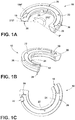
- FIGS. 1A-1C generally illustrate an embodiment of a spring isolator 10.
- Spring isolator 10 may include a ramp 18, a spring stop 20, a track/groove (i.e., spring track), 22, an inner wall 24, an outer wall 26, a locator pin 28, and/or a water drain 30.
- Spring isolator 10 may be configured (e.g., molded), of a flexible material (e.g., rubber).
- Spring isolator 10 may be configured to include a ramp 18 and/or a spring stop 20.
- Ramp 18 and/or spring stop 20 may be configured on opposite ends of spring isolator 10.
- a track/groove 22 may be configured to connect ramp 18 and/or spring stop 20.
- Track/groove 22 may include an inner wall 24 and/or an outer wall 26. Track/groove 22 may be configured to receive a spring (e.g., helical spring), such that an end of the spring may engage a spring stop 20 of a spring isolator 10.
- a spring e.g., helical spring
- One or more locator pins 28 may be integrated into spring isolator 10.
- One or more locator pin 28 may secure spring isolator 10 to a spring seat 32.
- locator pin is intended to encompass various formations that can be used as a locator.
- one or more water drains 30 may be included in spring isolator 10. Drains 30 may permit foreign and/or unwanted materials (e.g., water, debris) that may accumulate in spring isolator 10 to drain (e.g., exit).
- spring isolator 10 may be used in one or more locations in a vehicle suspension system.
- spring isolator 10 may be used in conjunction with a MacPherson strut system that may located in the front and/or rear of a vehicle.
- Spring isolator 10 may be configured at either end of the Macpherson strut system, or both.
- Spring isolator 10 may be configured for use in other vehicle suspension systems (e.g., double wishbone), that may include one or more coil springs 34 in either front and/or rear positions of a vehicle.
- spring isolator 10 may be engaged by coil spring 34.
- An end of coil spring 34 may engage spring stop 20 of spring isolator 10.
- Coil spring 34 may also engage a track/groove 22 that may extend radially from spring stop 20 to ramp 18.
- ramp 18 may be configured to begin approximately 184 degrees from spring stop 20. It should be understood that the position of ramp 18 relative to spring stop 20 is exemplary, and not limiting. Ramp 18 may be positioned at other angles relative to spring stop 20, such as, but not limited to, 145 degrees through 212 degrees. In embodiments, most of the vehicle suspension load transferred from coil spring 34 to spring isolator 10 may be concentrated at spring stop 20 and/or ramp 18. By including a reinforcing insert 14 within spring isolator 10, the vehicle suspension load previously concentrated at spring stop 20 and/or ramp 18 may be compensated (e.g., dispersed, distributed), throughout spring isolator 10 via track/groove 22.
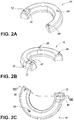
- FIGS. 2A-2C generally illustrate spring isolator 10.
- spring isolator 10 may be configured (e.g., molded), of a flexible material (e.g., rubber).
- cavity 12 may be included in spring isolator 10.
- cavity 12 may be configured in proximity to ramp 18.
- cavity 12 may be configured in proximity to spring stop 20.
- one or more cavities 12 may be configured about spring isolator 10.
- One or more cavities 12 may engage one or more raised portions 42 (see, e.g., FIG. 8 ), of spring seat 32.
- spring isolator 10 may include one or more locator pins 28 that may engage one or more locator pin holes 40 of spring seat 32.
- FIG. 3 generally illustrates reinforcing insert 14 associated with spring isolator 10.
- reinforcing insert may be disposed at least partially within spring isolator 10 (see, e.g., FIG. 5 ).
- Reinforcing insert 14 may include one or more flow holes 16, through which a moldable material (e.g., rubber, polymer), may flow.
- Reinforcing insert 14 may be constructed of materials that may strengthen spring isolator 10 (e.g., polymer, metal), and/or permit a load received from coil spring 34 to be compensated (e.g., distributed), via reinforcing insert 14.
- other suitably rigid and/or semi-rigid materials may be used to construct reinforcing insert 14.
- reinforcing insert 14 may be integrated (e.g., over-molded), by spring isolator 10 (see, e.g., FIGS. 5 and 8 ).
- Reinforcing insert 14 may include one or more flow holes (e.g., passages), 16.
- Flow holes 16 may permit a material (e.g., foam urethane elastomer), forming spring isolator 10 to pass through flow holes 16 and/or secure reinforcing insert within spring isolator 10.
- Reinforcing insert 14 may include ramp 18 that may be disposed at one end of reinforcing insert 14.
- Ramp 18 may engage track/groove 22, inner wall 24, and/or outer wall 26.
- Track/groove 22 may be configured with an incline (e.g., slope).
- Track/groove 22 may engage spring (e.g., coil, helical), 34.
- track/groove 22 of spring isolator 10 and/or reinforcing insert 14 may have a spring stop 20 at one end (i.e., first end), of track/groove 22 and a ramp 18 at the other end (e.g., second end), of track/groove 22.
- Spring stop 20 may include track/groove 22, inner wall 24, and/or outer wall 26.
- reinforcing insert 14 may include one or more locator pins 28. Locator pins 28 may be configured to engage spring seat 32 via one or more locator pin holes 40. In embodiments, locator pins 28 may be configured on a side of reinforcing insert 14 opposite of ramp 18 and/or spring stop 20.
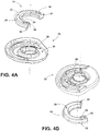
- FIGS. 4A-4B generally illustrate spring seat 32 associated with spring isolator 10.
- Spring seat 32 may include indentation 36 that may be configured to receive spring isolator 10.
- Spring seat 32 may include raised portion 42 that may be configured to engage cavity 12 of spring isolator 10.
- Cavity 12 may be included (i.e., integrated) in spring isolator 10.
- one or more cavities 12 and/or one or more locator pins 28 may engage and/or stabilize spring seat 10 within indentation 36.
- FIG. 5 generally illustrates spring seat 32 and coil spring 34 associated with spring isolator 10.
- Coil spring 34 may engage spring isolator 10 and/or spring seat 32. At least a portion of coil spring 34 may engage spring stop 20 of spring isolator 10. A portion of coil spring 34 extending from (e.g., adjacent to), the end of coil spring 34 may engage track/groove 22, inner wall 24, and/or outer wall 26 of spring isolator 10. At least a portion of coil spring 34 may engage ramp 18 of spring isolator 10. Ramp 18 may engage track/groove 22, inner wall 24, and/or outer wall 26.
- Spring seat 32 may be configured annularly around (e.g., about), shock passage 38. Shock passage 38 may be configured to receive and/or engage a shock absorber (e.g., damper).
- a shock absorber e.g., damper
- coil spring 34 may engage spring isolator 10. An end of the coil spring 34 may engage (e.g., contact), spring stop 20 of spring isolator 10. The coil spring 34 may be configured to engage ramp 18, track/groove 22, inner wall 24, and/or outer wall 26.
- a load may applied to coil spring 34 that may be transmitted (e.g., transferred), to spring isolator 10 and/or spring seat 32.
- the load may be applied in the form of a jounce and/or rebound load.
- a jounce load may be defined as the result of upward movement and/or compression of one or more suspension components, such as, but not limited to, coil spring 34.
- a rebound load may be defined as the downward movement and/or extension of one or more suspension components, such as, but not limited to, coil spring 34.
- ramp 18 and/or spring stop 20 may receive a large portion (e.g., 200 ⁇ 2000 N) of the load (e.g., jounce, rebound), transmitted by the coil spring to spring isolator 10.
- Spring isolator 10 may distribute and/or dissipate the load transmitted by the coil spring to spring seat 32.
- one or more locator pins 28 of spring isolator 10 may be configured to engage a spring seat 32 and/or prevent the movement (e.g., rotation), of spring isolator 10.
- FIGS. 6A-6B generally illustrate a spring seat 32 associated with a spring isolator (e.g., spring isolator 10 in FIGS. 1A-C , 2A-C , 4A-B ).
- spring isolator 10 may be associated with other suspension and/or body components of a vehicle and that the embodiments of spring seat 32 described herein are exemplary and not limiting.
- Spring seat 32 may include one or more locator pin holes 40 (i.e., receiving formations), that may engage one or more locator pins 28 of spring isolator 10.
- Locator pin holes 40 may be configured to engage locator pins 28 of different shapes and/or sizes (e.g., cylindrical, square), that may permit joining (e.g., assembly), of spring isolator 10 to spring seat 32 in one or more predetermined orientations.
- the configuration (e.g., placement), of locator pins 28 and/or locator pin holes 40 may permit the joining of spring isolator 10 and spring seat 32.
- spring isolator 10 may be configured to engage spring seat 32 annularly around (e.g., about), shock passage 38.
- FIGS. 7A-7B generally illustrate a spring seat 32 associated with a spring isolator (e.g., spring isolator 10 in FIGS. 1A-C , 2A-C , 4A-B ).
- Spring isolator 10 may be configured to engage an indentation 36 (e.g., as shown in FIG. 7B ), of spring seat 32.
- spring isolator 10 and/or spring seat 32 may be configured annularly about shock passage 38.
- One or more locator pins 28 of spring isolator 10 may engage one or more locator pin holes 40 of spring seat 32.
- Spring isolator 10 may include ramp 18, spring stop 20, track/groove 22, inner wall 24, outer wall 26, and/or water drain 30.
- Ramp 18 may be configured at one end of spring isolator 10. Ramp 18 may be configured to engage track/groove 22, inner wall 24, and/or outer wall 26 of spring isolator 10. In embodiments, at the opposite end of spring isolator 10, spring stop 20 may be configured to engage track/groove 22, inner wall 24, and/or outer wall 26 of spring isolator 10. In embodiments, one or more drains 30 may be configured to engage track/groove 22, inner wall 26, and/or outer wall 26 of spring isolator 10. In embodiments, drain 30 may be configured proximately to (e.g., near), ramp 18 and/or spring stop 20. In embodiments, drain 30 may be configured distally from (e.g., far), ramp 18 and/or spring stop 20. In embodiments, drain 30 may be configured to align with flow holes 16 and/or locator pin holes 40 of spring isolator 10 and spring seat 32, respectively.
- FIG. 8 generally illustrates spring seat 32 associated with spring isolator 10.
- Spring isolator 10 may be engage spring seat 32 via one or more locator pins 28.
- One or more locator pins 28 may be included with reinforcing insert 14 and/or spring isolator 10.
- locator pins 28 may engage spring seat 32 via one or more locator pin holes 40.
- locator pins 28 may include fastening elements (e.g., threads, rivets), that may secure spring isolator 10 to spring seat 40.
- locator pins 28 may be processed (e.g., welded, compressed, flattened), after insertion in locator pin holes 40.
- spring isolator 10 may include one or more cavities 12.
- Cavity 12 may be configured on spring isolator 10 such that cavity 12 may engage spring seat 32 via a raised portion 42 of spring seat 32.
- locator pins 28 and/or raised portion 42 may engage (e.g., interlock), with spring isolator 10. Locator pins 28 and/or raised portion 42 may permit spring isolator 10 to remain in indentation 36 of spring seat 32. In embodiments, locator pins 28 and/or raised portion 42 may permit an operator to position spring isolator 10 in indentation 36 of spring seat 10.
- joinder references do not necessarily imply that two elements are directly connected/coupled and in fixed relation to each other.
- the terms “electrically connected” and “in communication” are meant to be construed broadly to encompass both wired and wireless connections and communications. It is intended that all matter contained in the above description or shown in the accompanying drawings shall be interpreted as illustrative only and not limiting. Changes in detail or structure may be made without departing from the invention as defined in the appended claims.
Landscapes
- Engineering & Computer Science (AREA)
- Mechanical Engineering (AREA)
- General Engineering & Computer Science (AREA)
- Springs (AREA)
Description
- The present disclosure relates to spring isolators, including methods and systems of load compensating spring isolators.
- This background description is set forth below for the purpose of providing context only. Therefore, any aspects of this background description, to the extent that it does not otherwise qualify as prior art, is neither expressly nor impliedly admitted as prior art against the instant disclosure.
- A spring (e.g., coil, helical), may be used to store energy (e.g., loads), temporarily and/or absorb vibration and/or sharp impacts (e.g., shocks). A spring may be engaged by a spring isolator. The spring isolator may provide support and/or secure the coil spring in a particular position. The spring isolator may be attached to and/or in contact with a larger supporting member, such as a spring seat. The spring isolator may maintain the position of the coil spring as the coil spring may be compressed and/or expanded during operation. The isolator may compensate for the load delivered by the coil spring and/or may improve performance of the coil spring. Among other things, it may be desirable to provide a spring isolator that provides isolation of road noise and/or high frequency vibration. It may also be desirable to provide a spring isolator that provides additional and/or improved structural support. In that regard, it may be desirable to provide a spring isolator system in which a pierce point does not change and/or ride quality is not sacrificed.
-
US 2014/265081 A1 ,US 2016/107497 A1 andGB 2 241 765 A - The foregoing discussion is intended only to illustrate the present field and should not be taken as a disavowal of claim scope.
- In a first aspect of the invention, a spring isolator assembly comprises: a reinforcing insert, a spring isolator including a ramp and a spring stop, the spring isolator being configured of a flexible material that is configured to receive a portion of a spring, the spring isolator including a spring track, an inner wall, and an outer wall. The reinforcing insert is integrated by said spring isolator and said ramp and said spring stop are configured at opposite ends of said spring isolator. Said spring isolator includes at least one drain, wherein the drain is configured to remove water and/or debris from the spring track.
- In a second aspect of the invention, a spring isolator assembly comprises: a reinforcing insert, the reinforcing insert including a ramp and a coil spring stop; and a radial outer layer comprised of a moldable flexible material, the radial outer layer surrounding the reinforcing insert. The ramp is at a first end, the coil spring stop is at a second end. A thickness of the reinforcing insert, in a vertical direction, varies along a curved length of the reinforcing insert. The thickness of the ramp is greater than the thickness of the reinforcing insert adjacent the ramp. Said spring isolator assembly includes at least one drain to permit foreign and/ or unwanted materials that may accumulate in spring isolator assembly to drain.
- The foregoing and other aspects, features, details, utilities, and advantages of the present disclosure will be apparent from reading the following description and claims, and from reviewing the accompanying drawings.
-
-
FIGS. 1A-1C are top perspective views generally illustrating an embodiment of a spring isolator, in accordance with teachings of the present disclosure. -
FIGS. 2A-2C are bottom perspective views generally illustrating the embodiment of the spring isolator inFIGS. 1A-1C , in accordance with teachings of the present disclosure. -
FIG. 3 is a perspective view generally illustrating an embodiment of a reinforcing insert, in accordance with teachings of the present disclosure. -
FIGS. 4A-4B are perspective views generally illustrating embodiments of a spring isolator and a spring seat, in accordance with teachings of the present disclosure. -
FIG. 5 is a sectional perspective view generally illustrating an embodiment of a spring isolator, coil spring, and spring seat in accordance with teachings of the present disclosure. -
FIGS. 6A-6B are top and bottom perspective views, respectively, generally illustrating embodiments of a spring isolator and spring seat in accordance with teachings of the present disclosure. -
FIGS. 7A-7B are top and bottom views, respectively, generally illustrating embodiments of a spring isolator and spring seat in accordance with teachings of the present disclosure. -
FIG. 8 is a sectional perspective view generally illustrating an embodiment of a spring isolator and a spring seat in accordance with teachings of the present disclosure. - Referring now to the drawings,
FIGS. 1A-1C generally illustrate an embodiment of aspring isolator 10.Spring isolator 10 may include aramp 18, aspring stop 20, a track/groove (i.e., spring track), 22, aninner wall 24, anouter wall 26, alocator pin 28, and/or awater drain 30.Spring isolator 10 may be configured (e.g., molded), of a flexible material (e.g., rubber).Spring isolator 10 may be configured to include aramp 18 and/or aspring stop 20.Ramp 18 and/orspring stop 20 may be configured on opposite ends ofspring isolator 10. A track/groove 22 may be configured to connectramp 18 and/orspring stop 20. Track/groove 22 may include aninner wall 24 and/or anouter wall 26. Track/groove 22 may be configured to receive a spring (e.g., helical spring), such that an end of the spring may engage aspring stop 20 of aspring isolator 10. One ormore locator pins 28 may be integrated intospring isolator 10. One ormore locator pin 28 may securespring isolator 10 to aspring seat 32. The term "locator pin" is intended to encompass various formations that can be used as a locator. In embodiments, one ormore water drains 30 may be included inspring isolator 10.Drains 30 may permit foreign and/or unwanted materials (e.g., water, debris) that may accumulate inspring isolator 10 to drain (e.g., exit). - In embodiments,
spring isolator 10 may be used in one or more locations in a vehicle suspension system. For example and without limitation,spring isolator 10 may be used in conjunction with a MacPherson strut system that may located in the front and/or rear of a vehicle.Spring isolator 10 may be configured at either end of the Macpherson strut system, or both.Spring isolator 10 may be configured for use in other vehicle suspension systems (e.g., double wishbone), that may include one ormore coil springs 34 in either front and/or rear positions of a vehicle. - In embodiments,
spring isolator 10 may be engaged bycoil spring 34. An end ofcoil spring 34 may engagespring stop 20 ofspring isolator 10.Coil spring 34 may also engage a track/groove 22 that may extend radially fromspring stop 20 to ramp 18. In embodiments,ramp 18 may be configured to begin approximately 184 degrees fromspring stop 20. It should be understood that the position oframp 18 relative tospring stop 20 is exemplary, and not limiting.Ramp 18 may be positioned at other angles relative tospring stop 20, such as, but not limited to, 145 degrees through 212 degrees. In embodiments, most of the vehicle suspension load transferred fromcoil spring 34 tospring isolator 10 may be concentrated atspring stop 20 and/orramp 18. By including a reinforcinginsert 14 withinspring isolator 10, the vehicle suspension load previously concentrated atspring stop 20 and/orramp 18 may be compensated (e.g., dispersed, distributed), throughoutspring isolator 10 via track/groove 22. -
FIGS. 2A-2C generally illustratespring isolator 10. In embodiments,spring isolator 10 may be configured (e.g., molded), of a flexible material (e.g., rubber). In embodiments,cavity 12 may be included inspring isolator 10. In embodiments,cavity 12 may be configured in proximity to ramp 18. In embodiments,cavity 12 may be configured in proximity tospring stop 20. In embodiments, one ormore cavities 12 may be configured aboutspring isolator 10. One ormore cavities 12 may engage one or more raised portions 42 (see, e.g.,FIG. 8 ), ofspring seat 32. In embodiments,spring isolator 10 may include one or more locator pins 28 that may engage one or more locator pin holes 40 ofspring seat 32. -
FIG. 3 generally illustrates reinforcinginsert 14 associated withspring isolator 10. In embodiments, reinforcing insert may be disposed at least partially within spring isolator 10 (see, e.g.,FIG. 5 ). Reinforcinginsert 14 may include one or more flow holes 16, through which a moldable material (e.g., rubber, polymer), may flow. Reinforcinginsert 14 may be constructed of materials that may strengthen spring isolator 10 (e.g., polymer, metal), and/or permit a load received fromcoil spring 34 to be compensated (e.g., distributed), via reinforcinginsert 14. In embodiments, other suitably rigid and/or semi-rigid materials may be used to construct reinforcinginsert 14. - In embodiments, reinforcing
insert 14 may be integrated (e.g., over-molded), by spring isolator 10 (see, e.g.,FIGS. 5 and8 ). Reinforcinginsert 14 may include one or more flow holes (e.g., passages), 16. Flow holes 16 may permit a material (e.g., foam urethane elastomer), formingspring isolator 10 to pass through flow holes 16 and/or secure reinforcing insert withinspring isolator 10. Reinforcinginsert 14 may includeramp 18 that may be disposed at one end of reinforcinginsert 14.Ramp 18 may engage track/groove 22,inner wall 24, and/orouter wall 26. Track/groove 22 may be configured with an incline (e.g., slope). Track/groove 22 may engage spring (e.g., coil, helical), 34. - In embodiments, track/
groove 22 ofspring isolator 10 and/or reinforcinginsert 14 may have aspring stop 20 at one end (i.e., first end), of track/groove 22 and aramp 18 at the other end (e.g., second end), of track/groove 22.Spring stop 20 may include track/groove 22,inner wall 24, and/orouter wall 26. In embodiments, reinforcinginsert 14 may include one or more locator pins 28. Locator pins 28 may be configured to engagespring seat 32 via one or more locator pin holes 40. In embodiments, locator pins 28 may be configured on a side of reinforcinginsert 14 opposite oframp 18 and/orspring stop 20. -
FIGS. 4A-4B generally illustratespring seat 32 associated withspring isolator 10.Spring seat 32 may includeindentation 36 that may be configured to receivespring isolator 10.Spring seat 32 may include raisedportion 42 that may be configured to engagecavity 12 ofspring isolator 10.Cavity 12 may be included (i.e., integrated) inspring isolator 10. In embodiments, one ormore cavities 12 and/or one or more locator pins 28 may engage and/or stabilizespring seat 10 withinindentation 36. -
FIG. 5 generally illustratesspring seat 32 andcoil spring 34 associated withspring isolator 10.Coil spring 34 may engagespring isolator 10 and/orspring seat 32. At least a portion ofcoil spring 34 may engage spring stop 20 ofspring isolator 10. A portion ofcoil spring 34 extending from (e.g., adjacent to), the end ofcoil spring 34 may engage track/groove 22,inner wall 24, and/orouter wall 26 ofspring isolator 10. At least a portion ofcoil spring 34 may engageramp 18 ofspring isolator 10.Ramp 18 may engage track/groove 22,inner wall 24, and/orouter wall 26.Spring seat 32 may be configured annularly around (e.g., about),shock passage 38.Shock passage 38 may be configured to receive and/or engage a shock absorber (e.g., damper). - In embodiments,
coil spring 34 may engagespring isolator 10. An end of thecoil spring 34 may engage (e.g., contact),spring stop 20 ofspring isolator 10. Thecoil spring 34 may be configured to engageramp 18, track/groove 22,inner wall 24, and/orouter wall 26. In embodiments, a load may applied tocoil spring 34 that may be transmitted (e.g., transferred), to springisolator 10 and/orspring seat 32. The load may be applied in the form of a jounce and/or rebound load. A jounce load may be defined as the result of upward movement and/or compression of one or more suspension components, such as, but not limited to,coil spring 34. A rebound load may be defined as the downward movement and/or extension of one or more suspension components, such as, but not limited to,coil spring 34. - In embodiments,
ramp 18 and/orspring stop 20 may receive a large portion (e.g., 200 ― 2000 N) of the load (e.g., jounce, rebound), transmitted by the coil spring tospring isolator 10.Spring isolator 10 may distribute and/or dissipate the load transmitted by the coil spring to springseat 32. In embodiments, one or more locator pins 28 ofspring isolator 10 may be configured to engage aspring seat 32 and/or prevent the movement (e.g., rotation), ofspring isolator 10. -
FIGS. 6A-6B generally illustrate aspring seat 32 associated with a spring isolator (e.g.,spring isolator 10 inFIGS. 1A-C ,2A-C ,4A-B ). It should be understood thatspring isolator 10 may be associated with other suspension and/or body components of a vehicle and that the embodiments ofspring seat 32 described herein are exemplary and not limiting.Spring seat 32 may include one or more locator pin holes 40 (i.e., receiving formations), that may engage one or more locator pins 28 ofspring isolator 10. Locator pin holes 40 may be configured to engage locator pins 28 of different shapes and/or sizes (e.g., cylindrical, square), that may permit joining (e.g., assembly), ofspring isolator 10 to springseat 32 in one or more predetermined orientations. In embodiments, the configuration (e.g., placement), of locator pins 28 and/or locator pin holes 40 may permit the joining ofspring isolator 10 andspring seat 32. In embodiments,spring isolator 10 may be configured to engagespring seat 32 annularly around (e.g., about),shock passage 38. -
FIGS. 7A-7B generally illustrate aspring seat 32 associated with a spring isolator (e.g.,spring isolator 10 inFIGS. 1A-C ,2A-C ,4A-B ).Spring isolator 10 may be configured to engage an indentation 36 (e.g., as shown inFIG. 7B ), ofspring seat 32. In embodiments,spring isolator 10 and/orspring seat 32 may be configured annularly aboutshock passage 38. One or more locator pins 28 ofspring isolator 10 may engage one or more locator pin holes 40 ofspring seat 32.Spring isolator 10 may includeramp 18,spring stop 20, track/groove 22,inner wall 24,outer wall 26, and/orwater drain 30.Ramp 18 may be configured at one end ofspring isolator 10.Ramp 18 may be configured to engage track/groove 22,inner wall 24, and/orouter wall 26 ofspring isolator 10. In embodiments, at the opposite end ofspring isolator 10,spring stop 20 may be configured to engage track/groove 22,inner wall 24, and/orouter wall 26 ofspring isolator 10. In embodiments, one ormore drains 30 may be configured to engage track/groove 22,inner wall 26, and/orouter wall 26 ofspring isolator 10. In embodiments, drain 30 may be configured proximately to (e.g., near),ramp 18 and/orspring stop 20. In embodiments, drain 30 may be configured distally from (e.g., far),ramp 18 and/orspring stop 20. In embodiments, drain 30 may be configured to align withflow holes 16 and/or locator pin holes 40 ofspring isolator 10 andspring seat 32, respectively. -
FIG. 8 generally illustratesspring seat 32 associated withspring isolator 10.Spring isolator 10 may be engagespring seat 32 via one or more locator pins 28. One or more locator pins 28 may be included with reinforcinginsert 14 and/orspring isolator 10. In embodiments, locator pins 28 may engagespring seat 32 via one or more locator pin holes 40. In embodiments, locator pins 28 may include fastening elements (e.g., threads, rivets), that may securespring isolator 10 to springseat 40. In embodiments, locator pins 28 may be processed (e.g., welded, compressed, flattened), after insertion in locator pin holes 40. In embodiments,spring isolator 10 may include one ormore cavities 12.Cavity 12 may be configured onspring isolator 10 such thatcavity 12 may engagespring seat 32 via a raisedportion 42 ofspring seat 32. In embodiments, locator pins 28 and/or raisedportion 42 may engage (e.g., interlock), withspring isolator 10. Locator pins 28 and/or raisedportion 42 may permitspring isolator 10 to remain inindentation 36 ofspring seat 32. In embodiments, locator pins 28 and/or raisedportion 42 may permit an operator to positionspring isolator 10 inindentation 36 ofspring seat 10. - Various embodiments are described herein to various apparatuses, systems, and/or methods. Numerous specific details are set forth to provide a thorough understanding of the overall structure, function, manufacture, and use of the embodiments as described in the specification and illustrated in the accompanying drawings. It will be understood by those skilled in the art, however, that the embodiments may be practiced without such specific details. In other instances, well-known operations, components, and elements have not been described in detail so as not to obscure the embodiments described in the specification. Those of ordinary skill in the art will understand that the embodiments described and illustrated herein are nonlimiting examples, and thus it can be appreciated that the specific structural and functional details disclosed herein may be representative and do not necessarily limit the scope of the embodiments, the scope of which is defined solely by the appended claims.
- Reference throughout the specification to "various embodiments," "some embodiments," "one embodiment," or "an embodiment," or the like, means that a particular feature, structure, or characteristic described in connection with the embodiment is included in at least one embodiment. Thus, appearances of the phrases "in various embodiments," "in some embodiments," "in one embodiment," or "in an embodiment," or the like, in places throughout the specification are not necessarily all referring to the same embodiment. Furthermore, the particular features, structures, or characteristics may be combined in any suitable manner in one or more embodiments. Thus, the particular features, structures, or characteristics illustrated or described in connection with one embodiment may be combined, in whole or in part, with the features, structures, or characteristics of one or more other embodiments without limitation given that such combination is not illogical or non-functional.
- Although only certain embodiments have been described above with a certain degree of particularity, those skilled in the art could make numerous alterations to the disclosed embodiments without departing from the scope of this disclosure. All directional references (e.g., plus, minus, upper, lower, upward, downward, left, right, leftward, rightward, top, bottom, above, below, vertical, horizontal, clockwise, and counterclockwise) are only used for identification purposes to aid the reader's understanding of the present disclosure, and do not create limitations, particularly as to the position, orientation, or use of embodiments. Joinder references (e.g., attached, coupled, connected, and the like) are to be construed broadly and may include intermediate members between a connection of elements and relative movement between elements. As such, joinder references do not necessarily imply that two elements are directly connected/coupled and in fixed relation to each other. Additionally, the terms "electrically connected" and "in communication" are meant to be construed broadly to encompass both wired and wireless connections and communications. It is intended that all matter contained in the above description or shown in the accompanying drawings shall be interpreted as illustrative only and not limiting. Changes in detail or structure may be made without departing from the invention as defined in the appended claims.
Claims (15)
- A spring isolator assembly, the assembly comprising:a reinforcing insert (14),a spring isolator (10) including a ramp (18) and a spring stop (20), the spring isolator being configured of a flexible material that is configured to receive a portion of a spring (34), the spring isolator (10) including a spring track (22), an inner wall (24), and an outer wall (26),wherein the reinforcing insert (14) is integrated by said spring isolator (10) and said ramp (18) and said spring stop (20) are configured at opposite ends of said spring isolator (10), wherein said spring isolator (10) includes at least a drain (30), wherein the drain (30) is configured to remove water and/or debris from the spring track (22).
- The spring isolator assembly of claim 1, wherein the reinforcing insert (14) is made of a metal or polymer.
- The spring isolator assembly of claim 1, wherein the reinforcing insert (14) further comprising a passage (16) through which a portion of the outer layer engages the reinforcing insert (14).
- The spring isolator assembly of claim 1, wherein said spring isolator (10) includes locator pin (28) that protrudes from said spring isolator (10) and is configured to secure said spring isolator (10) to a spring seat (32).
- The spring isolator assembly of claim 1, wherein the spring track (22) is configured to connect the ramp (18) and the spring stop (20).
- The spring isolator assembly of claim 5, wherein said spring track (22) is configured to receive a spring (34).
- The spring isolator assembly of claim 6, wherein the inner wall (24) and the outer wall (26) engage a portion of the ramp (18).
- The spring isolator assembly of claim 1, wherein said spring stop (20) is configured to engage an end of a coil spring (34) and/or said spring track (22) is configured to engage a coil spring (34).
- The spring isolator assembly of claim 1, wherein drain (30) is configured proximately to said ramp (18) and/or said spring stop (20).
- The spring isolator assembly of claim 1, wherein said spring isolator (10) further comprising a cavity (12), wherein the cavity (12) is configured to engage a raised portion (42) of a spring seat (32).
- A spring isolator assembly, the assembly comprising:a reinforcing insert (14), wherein the reinforcing insert (14) includes a ramp (18) and a coil spring stop (20); anda radial outer layer comprised of a moldable flexible material, wherein the radial outer layer surrounds the reinforcing insert (14),wherein the ramp (18) is at a first end, the coil spring stop (20) is at a second end and a thickness of the reinforcing insert (14), in a vertical direction, varies along a curved length of the reinforcing insert (14), and the thickness of the ramp (18) is greater than the thickness of the reinforcing insert (14) adjacent the ramp (18), wherein said spring isolator assembly includes at least a drain (30) to permit foreign and/or unwanted materials that may accumulate in spring isolator assembly to drain.
- The spring isolator assembly of claim 11, wherein the reinforcing insert (14) includes a plurality of passages (16) configured to engage one or more of the radial outer layer and a locator pin (28) to selectively engage a coil spring seat (32).
- The spring isolator assembly of claim 11, wherein the ramp (18) is situated between 145 degrees and 212 degrees radially from the spring stop (20).
- The spring isolator of assembly claim 11, wherein the radial outer layer includes a coil spring track (22) disposed between an inner wall (24) and an outer wall (26) for selectively engaging a coil spring (34).
- The spring isolator of assembly claim 11, further comprising at least one of a locator pin (28), raised portion (42), and/or a cavity (12) for selectively engaging a portion of a coil spring seat (32).
Applications Claiming Priority (3)
| Application Number | Priority Date | Filing Date | Title |
|---|---|---|---|
| US201662407174P | 2016-10-12 | 2016-10-12 | |
| US15/729,902 US10495170B2 (en) | 2016-10-12 | 2017-10-11 | Load compensating spring isolator |
| PCT/US2017/056328 WO2018071661A1 (en) | 2016-10-12 | 2017-10-12 | Load compensating spring isolator |
Publications (2)
| Publication Number | Publication Date |
|---|---|
| EP3526488A1 EP3526488A1 (en) | 2019-08-21 |
| EP3526488B1 true EP3526488B1 (en) | 2021-12-01 |
Family
ID=61829764
Family Applications (1)
| Application Number | Title | Priority Date | Filing Date |
|---|---|---|---|
| EP17793759.6A Active EP3526488B1 (en) | 2016-10-12 | 2017-10-12 | Load compensating spring isolator |
Country Status (4)
| Country | Link |
|---|---|
| US (1) | US10495170B2 (en) |
| EP (1) | EP3526488B1 (en) |
| CN (1) | CN109844353A (en) |
| WO (1) | WO2018071661A1 (en) |
Families Citing this family (6)
| Publication number | Priority date | Publication date | Assignee | Title |
|---|---|---|---|---|
| KR102039936B1 (en) * | 2019-04-19 | 2019-11-04 | 대원강업주식회사 | Bonded-Pad and Manufacturing Method of Same for Coil-Spring of Car Suspension |
| JP7527921B2 (en) * | 2020-10-01 | 2024-08-05 | 株式会社Subaru | Suspension system |
| EP4291418A4 (en) | 2022-05-05 | 2024-07-31 | Mitesh Rasal | SUSPENSION SYSTEM |
| WO2024137400A1 (en) * | 2022-12-20 | 2024-06-27 | Basf Se | Hybrid coil spring isolator |
| US12479251B2 (en) | 2024-02-06 | 2025-11-25 | Fca Us Llc | Rear lower isolator |
| WO2026046779A1 (en) | 2024-08-29 | 2026-03-05 | Basf Polyurethanes Gmbh | Coil spring isolator and corresponding coil spring assembly |
Citations (3)
| Publication number | Priority date | Publication date | Assignee | Title |
|---|---|---|---|---|
| GB2241765A (en) * | 1990-03-09 | 1991-09-11 | Fichtel & Sachs Ag | Suspension strut |
| US20140265081A1 (en) * | 2013-03-12 | 2014-09-18 | Showa Corporation | Elastic sheet and suspension apparatus |
| US20160107497A1 (en) * | 2014-10-21 | 2016-04-21 | Ford Global Technologies, Llc | Spring isolators and suspension systems incorporating same |
Family Cites Families (11)
| Publication number | Priority date | Publication date | Assignee | Title |
|---|---|---|---|---|
| US6149171A (en) * | 1999-03-31 | 2000-11-21 | Daimlerchrysler Corporation | Spring isolator for a motor vehicle suspension |
| US20030222386A1 (en) | 2001-11-27 | 2003-12-04 | Markus Duerre | Combined spring seat isolator and mass damper |
| JP4055845B2 (en) * | 2002-05-08 | 2008-03-05 | 株式会社ショーワ | Dust cover receiving structure of hydraulic shock absorber |
| DE102005032449A1 (en) | 2005-07-12 | 2007-01-18 | Zf Friedrichshafen Ag | Spring plate Pad |
| CN100497989C (en) * | 2006-02-21 | 2009-06-10 | 东海橡胶工业株式会社 | Spring seat of suspension for automotive vehicle |
| JP5151770B2 (en) * | 2007-11-26 | 2013-02-27 | 日産自動車株式会社 | Lower spring seat mounting structure and lower spring seat |
| JP5293340B2 (en) * | 2009-03-30 | 2013-09-18 | スズキ株式会社 | Spring seat and spring seat mounting structure |
| DE102010028290B4 (en) | 2010-04-28 | 2019-01-31 | Zf Friedrichshafen Ag | spring plate |
| JP5961128B2 (en) * | 2013-03-21 | 2016-08-02 | Kyb株式会社 | Spring rubber seat and strut suspension |
| KR102300647B1 (en) * | 2014-10-30 | 2021-09-10 | 현대모비스 주식회사 | Suspention Of Multilink |
| CN205533992U (en) * | 2016-01-27 | 2016-08-31 | 安徽中鼎密封件股份有限公司 | Automobile shock absorber utensils spring rubber cushion mat |
-
2017
- 2017-10-11 US US15/729,902 patent/US10495170B2/en active Active
- 2017-10-12 CN CN201780062587.0A patent/CN109844353A/en active Pending
- 2017-10-12 EP EP17793759.6A patent/EP3526488B1/en active Active
- 2017-10-12 WO PCT/US2017/056328 patent/WO2018071661A1/en not_active Ceased
Patent Citations (3)
| Publication number | Priority date | Publication date | Assignee | Title |
|---|---|---|---|---|
| GB2241765A (en) * | 1990-03-09 | 1991-09-11 | Fichtel & Sachs Ag | Suspension strut |
| US20140265081A1 (en) * | 2013-03-12 | 2014-09-18 | Showa Corporation | Elastic sheet and suspension apparatus |
| US20160107497A1 (en) * | 2014-10-21 | 2016-04-21 | Ford Global Technologies, Llc | Spring isolators and suspension systems incorporating same |
Also Published As
| Publication number | Publication date |
|---|---|
| US10495170B2 (en) | 2019-12-03 |
| CN109844353A (en) | 2019-06-04 |
| WO2018071661A1 (en) | 2018-04-19 |
| EP3526488A1 (en) | 2019-08-21 |
| US20180100556A1 (en) | 2018-04-12 |
Similar Documents
| Publication | Publication Date | Title |
|---|---|---|
| US10495170B2 (en) | Load compensating spring isolator | |
| US20180111436A1 (en) | Proportional radial loading spring isolator | |
| US7389977B1 (en) | Body mount assembly with combined shear and compression style components | |
| US10442262B2 (en) | Hybrid arm and method of manufacturing same | |
| CN105377594B (en) | Vehicle suspension and its leaf spring | |
| US8936264B2 (en) | One-shell spring suspension arm | |
| CN104080626B (en) | Vehicle suspension including lightweight leaf spring assemblies | |
| US9950583B2 (en) | Spring seat | |
| CN105523089A (en) | Support structure component for connecting a spring strut to a vehicle body, method for mounting a spring strut on a vehicle body and vehicle body | |
| CN103534506A (en) | Gasket assembly | |
| CN105387074A (en) | Strut bearing unit, motor vehicle equipped with such a strut bearing unit and manufacturing method | |
| US9399381B2 (en) | Vehicle suspension device | |
| US20030222386A1 (en) | Combined spring seat isolator and mass damper | |
| EP3290241A1 (en) | Hybrid lower arm | |
| KR101479594B1 (en) | Insulator of suspension | |
| CN106627020A (en) | Vehicle spring assembly | |
| US20040012168A1 (en) | Suspension system with magnetic resiliency | |
| KR20170099712A (en) | Trailing arm bush | |
| KR101582854B1 (en) | Tunable type of Front Air suspension for vehicles | |
| US11577569B2 (en) | Bushing snubber bracket | |
| KR101724457B1 (en) | Structure for mounting rear shock absorber of vehicle | |
| KR101372926B1 (en) | Insulator for suspension | |
| KR101382966B1 (en) | Rear axle module manufacturing process and coupled tubular beam axle suspension thereof | |
| US20160009154A1 (en) | Suspension member | |
| KR102452687B1 (en) | Insulator bush for strut type suspension in vehicle |
Legal Events
| Date | Code | Title | Description |
|---|---|---|---|
| STAA | Information on the status of an ep patent application or granted ep patent |
Free format text: STATUS: UNKNOWN |
|
| STAA | Information on the status of an ep patent application or granted ep patent |
Free format text: STATUS: THE INTERNATIONAL PUBLICATION HAS BEEN MADE |
|
| PUAI | Public reference made under article 153(3) epc to a published international application that has entered the european phase |
Free format text: ORIGINAL CODE: 0009012 |
|
| STAA | Information on the status of an ep patent application or granted ep patent |
Free format text: STATUS: REQUEST FOR EXAMINATION WAS MADE |
|
| 17P | Request for examination filed |
Effective date: 20190503 |
|
| AK | Designated contracting states |
Kind code of ref document: A1 Designated state(s): AL AT BE BG CH CY CZ DE DK EE ES FI FR GB GR HR HU IE IS IT LI LT LU LV MC MK MT NL NO PL PT RO RS SE SI SK SM TR |
|
| AX | Request for extension of the european patent |
Extension state: BA ME |
|
| RIN1 | Information on inventor provided before grant (corrected) |
Inventor name: LOVE, MICKEY, L. Inventor name: DUTTON, LEE, HAYDEN Inventor name: CUMMINGS, NEIL, STEWART |
|
| RIN1 | Information on inventor provided before grant (corrected) |
Inventor name: DUTTON, LEE, HAYDEN Inventor name: LOVE, MICKEY, L. Inventor name: CUMMINGS, NEIL, STEWART |
|
| DAV | Request for validation of the european patent (deleted) | ||
| DAX | Request for extension of the european patent (deleted) | ||
| STAA | Information on the status of an ep patent application or granted ep patent |
Free format text: STATUS: EXAMINATION IS IN PROGRESS |
|
| 17Q | First examination report despatched |
Effective date: 20200316 |
|
| GRAP | Despatch of communication of intention to grant a patent |
Free format text: ORIGINAL CODE: EPIDOSNIGR1 |
|
| STAA | Information on the status of an ep patent application or granted ep patent |
Free format text: STATUS: GRANT OF PATENT IS INTENDED |
|
| INTG | Intention to grant announced |
Effective date: 20210518 |
|
| GRAS | Grant fee paid |
Free format text: ORIGINAL CODE: EPIDOSNIGR3 |
|
| RIN1 | Information on inventor provided before grant (corrected) |
Inventor name: DUTTON, LEE HAYDEN Inventor name: CUMMINGS, NEIL, STEWART Inventor name: LOVE, MICKEY L. |
|
| GRAA | (expected) grant |
Free format text: ORIGINAL CODE: 0009210 |
|
| STAA | Information on the status of an ep patent application or granted ep patent |
Free format text: STATUS: THE PATENT HAS BEEN GRANTED |
|
| AK | Designated contracting states |
Kind code of ref document: B1 Designated state(s): AL AT BE BG CH CY CZ DE DK EE ES FI FR GB GR HR HU IE IS IT LI LT LU LV MC MK MT NL NO PL PT RO RS SE SI SK SM TR |
|
| REG | Reference to a national code |
Ref country code: GB Ref legal event code: FG4D |
|
| REG | Reference to a national code |
Ref country code: AT Ref legal event code: REF Ref document number: 1452044 Country of ref document: AT Kind code of ref document: T Effective date: 20211215 Ref country code: CH Ref legal event code: EP |
|
| REG | Reference to a national code |
Ref country code: IE Ref legal event code: FG4D |
|
| REG | Reference to a national code |
Ref country code: DE Ref legal event code: R096 Ref document number: 602017050297 Country of ref document: DE |
|
| REG | Reference to a national code |
Ref country code: LT Ref legal event code: MG9D |
|
| REG | Reference to a national code |
Ref country code: NL Ref legal event code: MP Effective date: 20211201 |
|
| REG | Reference to a national code |
Ref country code: AT Ref legal event code: MK05 Ref document number: 1452044 Country of ref document: AT Kind code of ref document: T Effective date: 20211201 |
|
| PG25 | Lapsed in a contracting state [announced via postgrant information from national office to epo] |
Ref country code: RS Free format text: LAPSE BECAUSE OF FAILURE TO SUBMIT A TRANSLATION OF THE DESCRIPTION OR TO PAY THE FEE WITHIN THE PRESCRIBED TIME-LIMIT Effective date: 20211201 Ref country code: LT Free format text: LAPSE BECAUSE OF FAILURE TO SUBMIT A TRANSLATION OF THE DESCRIPTION OR TO PAY THE FEE WITHIN THE PRESCRIBED TIME-LIMIT Effective date: 20211201 Ref country code: FI Free format text: LAPSE BECAUSE OF FAILURE TO SUBMIT A TRANSLATION OF THE DESCRIPTION OR TO PAY THE FEE WITHIN THE PRESCRIBED TIME-LIMIT Effective date: 20211201 Ref country code: BG Free format text: LAPSE BECAUSE OF FAILURE TO SUBMIT A TRANSLATION OF THE DESCRIPTION OR TO PAY THE FEE WITHIN THE PRESCRIBED TIME-LIMIT Effective date: 20220301 Ref country code: AT Free format text: LAPSE BECAUSE OF FAILURE TO SUBMIT A TRANSLATION OF THE DESCRIPTION OR TO PAY THE FEE WITHIN THE PRESCRIBED TIME-LIMIT Effective date: 20211201 |
|
| PG25 | Lapsed in a contracting state [announced via postgrant information from national office to epo] |
Ref country code: SE Free format text: LAPSE BECAUSE OF FAILURE TO SUBMIT A TRANSLATION OF THE DESCRIPTION OR TO PAY THE FEE WITHIN THE PRESCRIBED TIME-LIMIT Effective date: 20211201 Ref country code: PL Free format text: LAPSE BECAUSE OF FAILURE TO SUBMIT A TRANSLATION OF THE DESCRIPTION OR TO PAY THE FEE WITHIN THE PRESCRIBED TIME-LIMIT Effective date: 20211201 Ref country code: NO Free format text: LAPSE BECAUSE OF FAILURE TO SUBMIT A TRANSLATION OF THE DESCRIPTION OR TO PAY THE FEE WITHIN THE PRESCRIBED TIME-LIMIT Effective date: 20220301 Ref country code: LV Free format text: LAPSE BECAUSE OF FAILURE TO SUBMIT A TRANSLATION OF THE DESCRIPTION OR TO PAY THE FEE WITHIN THE PRESCRIBED TIME-LIMIT Effective date: 20211201 Ref country code: HR Free format text: LAPSE BECAUSE OF FAILURE TO SUBMIT A TRANSLATION OF THE DESCRIPTION OR TO PAY THE FEE WITHIN THE PRESCRIBED TIME-LIMIT Effective date: 20211201 Ref country code: GR Free format text: LAPSE BECAUSE OF FAILURE TO SUBMIT A TRANSLATION OF THE DESCRIPTION OR TO PAY THE FEE WITHIN THE PRESCRIBED TIME-LIMIT Effective date: 20220302 Ref country code: ES Free format text: LAPSE BECAUSE OF FAILURE TO SUBMIT A TRANSLATION OF THE DESCRIPTION OR TO PAY THE FEE WITHIN THE PRESCRIBED TIME-LIMIT Effective date: 20211201 |
|
| PG25 | Lapsed in a contracting state [announced via postgrant information from national office to epo] |
Ref country code: NL Free format text: LAPSE BECAUSE OF FAILURE TO SUBMIT A TRANSLATION OF THE DESCRIPTION OR TO PAY THE FEE WITHIN THE PRESCRIBED TIME-LIMIT Effective date: 20211201 |
|
| PG25 | Lapsed in a contracting state [announced via postgrant information from national office to epo] |
Ref country code: SM Free format text: LAPSE BECAUSE OF FAILURE TO SUBMIT A TRANSLATION OF THE DESCRIPTION OR TO PAY THE FEE WITHIN THE PRESCRIBED TIME-LIMIT Effective date: 20211201 Ref country code: SK Free format text: LAPSE BECAUSE OF FAILURE TO SUBMIT A TRANSLATION OF THE DESCRIPTION OR TO PAY THE FEE WITHIN THE PRESCRIBED TIME-LIMIT Effective date: 20211201 Ref country code: RO Free format text: LAPSE BECAUSE OF FAILURE TO SUBMIT A TRANSLATION OF THE DESCRIPTION OR TO PAY THE FEE WITHIN THE PRESCRIBED TIME-LIMIT Effective date: 20211201 Ref country code: PT Free format text: LAPSE BECAUSE OF FAILURE TO SUBMIT A TRANSLATION OF THE DESCRIPTION OR TO PAY THE FEE WITHIN THE PRESCRIBED TIME-LIMIT Effective date: 20220401 Ref country code: EE Free format text: LAPSE BECAUSE OF FAILURE TO SUBMIT A TRANSLATION OF THE DESCRIPTION OR TO PAY THE FEE WITHIN THE PRESCRIBED TIME-LIMIT Effective date: 20211201 Ref country code: CZ Free format text: LAPSE BECAUSE OF FAILURE TO SUBMIT A TRANSLATION OF THE DESCRIPTION OR TO PAY THE FEE WITHIN THE PRESCRIBED TIME-LIMIT Effective date: 20211201 |
|
| REG | Reference to a national code |
Ref country code: DE Ref legal event code: R097 Ref document number: 602017050297 Country of ref document: DE |
|
| PG25 | Lapsed in a contracting state [announced via postgrant information from national office to epo] |
Ref country code: IS Free format text: LAPSE BECAUSE OF FAILURE TO SUBMIT A TRANSLATION OF THE DESCRIPTION OR TO PAY THE FEE WITHIN THE PRESCRIBED TIME-LIMIT Effective date: 20220401 |
|
| PLBE | No opposition filed within time limit |
Free format text: ORIGINAL CODE: 0009261 |
|
| STAA | Information on the status of an ep patent application or granted ep patent |
Free format text: STATUS: NO OPPOSITION FILED WITHIN TIME LIMIT |
|
| PG25 | Lapsed in a contracting state [announced via postgrant information from national office to epo] |
Ref country code: DK Free format text: LAPSE BECAUSE OF FAILURE TO SUBMIT A TRANSLATION OF THE DESCRIPTION OR TO PAY THE FEE WITHIN THE PRESCRIBED TIME-LIMIT Effective date: 20211201 Ref country code: AL Free format text: LAPSE BECAUSE OF FAILURE TO SUBMIT A TRANSLATION OF THE DESCRIPTION OR TO PAY THE FEE WITHIN THE PRESCRIBED TIME-LIMIT Effective date: 20211201 |
|
| 26N | No opposition filed |
Effective date: 20220902 |
|
| PG25 | Lapsed in a contracting state [announced via postgrant information from national office to epo] |
Ref country code: SI Free format text: LAPSE BECAUSE OF FAILURE TO SUBMIT A TRANSLATION OF THE DESCRIPTION OR TO PAY THE FEE WITHIN THE PRESCRIBED TIME-LIMIT Effective date: 20211201 |
|
| PG25 | Lapsed in a contracting state [announced via postgrant information from national office to epo] |
Ref country code: MC Free format text: LAPSE BECAUSE OF FAILURE TO SUBMIT A TRANSLATION OF THE DESCRIPTION OR TO PAY THE FEE WITHIN THE PRESCRIBED TIME-LIMIT Effective date: 20211201 Ref country code: IT Free format text: LAPSE BECAUSE OF FAILURE TO SUBMIT A TRANSLATION OF THE DESCRIPTION OR TO PAY THE FEE WITHIN THE PRESCRIBED TIME-LIMIT Effective date: 20211201 |
|
| REG | Reference to a national code |
Ref country code: CH Ref legal event code: PL |
|
| REG | Reference to a national code |
Ref country code: BE Ref legal event code: MM Effective date: 20221031 |
|
| PG25 | Lapsed in a contracting state [announced via postgrant information from national office to epo] |
Ref country code: LU Free format text: LAPSE BECAUSE OF NON-PAYMENT OF DUE FEES Effective date: 20221012 |
|
| PG25 | Lapsed in a contracting state [announced via postgrant information from national office to epo] |
Ref country code: LI Free format text: LAPSE BECAUSE OF NON-PAYMENT OF DUE FEES Effective date: 20221031 Ref country code: CH Free format text: LAPSE BECAUSE OF NON-PAYMENT OF DUE FEES Effective date: 20221031 |
|
| PG25 | Lapsed in a contracting state [announced via postgrant information from national office to epo] |
Ref country code: BE Free format text: LAPSE BECAUSE OF NON-PAYMENT OF DUE FEES Effective date: 20221031 |
|
| PG25 | Lapsed in a contracting state [announced via postgrant information from national office to epo] |
Ref country code: IE Free format text: LAPSE BECAUSE OF NON-PAYMENT OF DUE FEES Effective date: 20221012 |
|
| PG25 | Lapsed in a contracting state [announced via postgrant information from national office to epo] |
Ref country code: HU Free format text: LAPSE BECAUSE OF FAILURE TO SUBMIT A TRANSLATION OF THE DESCRIPTION OR TO PAY THE FEE WITHIN THE PRESCRIBED TIME-LIMIT; INVALID AB INITIO Effective date: 20171012 |
|
| PG25 | Lapsed in a contracting state [announced via postgrant information from national office to epo] |
Ref country code: CY Free format text: LAPSE BECAUSE OF FAILURE TO SUBMIT A TRANSLATION OF THE DESCRIPTION OR TO PAY THE FEE WITHIN THE PRESCRIBED TIME-LIMIT Effective date: 20211201 |
|
| PG25 | Lapsed in a contracting state [announced via postgrant information from national office to epo] |
Ref country code: MK Free format text: LAPSE BECAUSE OF FAILURE TO SUBMIT A TRANSLATION OF THE DESCRIPTION OR TO PAY THE FEE WITHIN THE PRESCRIBED TIME-LIMIT Effective date: 20211201 |
|
| PG25 | Lapsed in a contracting state [announced via postgrant information from national office to epo] |
Ref country code: MT Free format text: LAPSE BECAUSE OF FAILURE TO SUBMIT A TRANSLATION OF THE DESCRIPTION OR TO PAY THE FEE WITHIN THE PRESCRIBED TIME-LIMIT Effective date: 20211201 |
|
| PGFP | Annual fee paid to national office [announced via postgrant information from national office to epo] |
Ref country code: DE Payment date: 20241031 Year of fee payment: 8 |
|
| PGFP | Annual fee paid to national office [announced via postgrant information from national office to epo] |
Ref country code: GB Payment date: 20241030 Year of fee payment: 8 |
|
| PGFP | Annual fee paid to national office [announced via postgrant information from national office to epo] |
Ref country code: FR Payment date: 20241030 Year of fee payment: 8 |
|
| PG25 | Lapsed in a contracting state [announced via postgrant information from national office to epo] |
Ref country code: TR Free format text: LAPSE BECAUSE OF FAILURE TO SUBMIT A TRANSLATION OF THE DESCRIPTION OR TO PAY THE FEE WITHIN THE PRESCRIBED TIME-LIMIT Effective date: 20211201 |