EP3526416B1 - Einrastbarer rohranordnung und verfahren zur herstellung - Google Patents
Einrastbarer rohranordnung und verfahren zur herstellung Download PDFInfo
- Publication number
- EP3526416B1 EP3526416B1 EP17862057.1A EP17862057A EP3526416B1 EP 3526416 B1 EP3526416 B1 EP 3526416B1 EP 17862057 A EP17862057 A EP 17862057A EP 3526416 B1 EP3526416 B1 EP 3526416B1
- Authority
- EP
- European Patent Office
- Prior art keywords
- snap member
- snap
- male
- female
- elongated
- Prior art date
- Legal status (The legal status is an assumption and is not a legal conclusion. Google has not performed a legal analysis and makes no representation as to the accuracy of the status listed.)
- Active
Links
- 238000004519 manufacturing process Methods 0.000 title claims description 16
- 238000000034 method Methods 0.000 claims description 13
- 239000000853 adhesive Substances 0.000 claims description 11
- 230000001070 adhesive effect Effects 0.000 claims description 11
- 229920002430 Fibre-reinforced plastic Polymers 0.000 claims description 2
- 239000011151 fibre-reinforced plastic Substances 0.000 claims description 2
- 239000011152 fibreglass Substances 0.000 description 4
- 230000006835 compression Effects 0.000 description 3
- 238000007906 compression Methods 0.000 description 3
- 239000000463 material Substances 0.000 description 3
- 230000005489 elastic deformation Effects 0.000 description 2
- 239000003365 glass fiber Substances 0.000 description 2
- 230000013011 mating Effects 0.000 description 2
- 239000002952 polymeric resin Substances 0.000 description 2
- 229920003002 synthetic resin Polymers 0.000 description 2
- 229920002748 Basalt fiber Polymers 0.000 description 1
- 229920000049 Carbon (fiber) Polymers 0.000 description 1
- 239000004593 Epoxy Substances 0.000 description 1
- 229920000271 Kevlar® Polymers 0.000 description 1
- 230000002411 adverse Effects 0.000 description 1
- 239000004917 carbon fiber Substances 0.000 description 1
- 238000010276 construction Methods 0.000 description 1
- 239000004035 construction material Substances 0.000 description 1
- 238000005516 engineering process Methods 0.000 description 1
- 238000001125 extrusion Methods 0.000 description 1
- 230000002349 favourable effect Effects 0.000 description 1
- 239000004761 kevlar Substances 0.000 description 1
- 229920000728 polyester Polymers 0.000 description 1
- 229920002635 polyurethane Polymers 0.000 description 1
- 239000004814 polyurethane Substances 0.000 description 1
- 229920005749 polyurethane resin Polymers 0.000 description 1
- 239000012783 reinforcing fiber Substances 0.000 description 1
- 238000009877 rendering Methods 0.000 description 1
- 239000000126 substance Substances 0.000 description 1
- 229920001187 thermosetting polymer Polymers 0.000 description 1
- 229920001567 vinyl ester resin Polymers 0.000 description 1
Images


Classifications
-
- F—MECHANICAL ENGINEERING; LIGHTING; HEATING; WEAPONS; BLASTING
- F16—ENGINEERING ELEMENTS AND UNITS; GENERAL MEASURES FOR PRODUCING AND MAINTAINING EFFECTIVE FUNCTIONING OF MACHINES OR INSTALLATIONS; THERMAL INSULATION IN GENERAL
- F16L—PIPES; JOINTS OR FITTINGS FOR PIPES; SUPPORTS FOR PIPES, CABLES OR PROTECTIVE TUBING; MEANS FOR THERMAL INSULATION IN GENERAL
- F16L9/00—Rigid pipes
- F16L9/22—Pipes composed of a plurality of segments
-
- E—FIXED CONSTRUCTIONS
- E04—BUILDING
- E04B—GENERAL BUILDING CONSTRUCTIONS; WALLS, e.g. PARTITIONS; ROOFS; FLOORS; CEILINGS; INSULATION OR OTHER PROTECTION OF BUILDINGS
- E04B1/00—Constructions in general; Structures which are not restricted either to walls, e.g. partitions, or floors or ceilings or roofs
- E04B1/38—Connections for building structures in general
- E04B1/61—Connections for building structures in general of slab-shaped building elements with each other
-
- B—PERFORMING OPERATIONS; TRANSPORTING
- B29—WORKING OF PLASTICS; WORKING OF SUBSTANCES IN A PLASTIC STATE IN GENERAL
- B29C—SHAPING OR JOINING OF PLASTICS; SHAPING OF MATERIAL IN A PLASTIC STATE, NOT OTHERWISE PROVIDED FOR; AFTER-TREATMENT OF THE SHAPED PRODUCTS, e.g. REPAIRING
- B29C70/00—Shaping composites, i.e. plastics material comprising reinforcements, fillers or preformed parts, e.g. inserts
- B29C70/04—Shaping composites, i.e. plastics material comprising reinforcements, fillers or preformed parts, e.g. inserts comprising reinforcements only, e.g. self-reinforcing plastics
- B29C70/28—Shaping operations therefor
- B29C70/40—Shaping or impregnating by compression not applied
- B29C70/50—Shaping or impregnating by compression not applied for producing articles of indefinite length, e.g. prepregs, sheet moulding compounds [SMC] or cross moulding compounds [XMC]
- B29C70/52—Pultrusion, i.e. forming and compressing by continuously pulling through a die
-
- E—FIXED CONSTRUCTIONS
- E04—BUILDING
- E04B—GENERAL BUILDING CONSTRUCTIONS; WALLS, e.g. PARTITIONS; ROOFS; FLOORS; CEILINGS; INSULATION OR OTHER PROTECTION OF BUILDINGS
- E04B1/00—Constructions in general; Structures which are not restricted either to walls, e.g. partitions, or floors or ceilings or roofs
- E04B1/38—Connections for building structures in general
-
- E—FIXED CONSTRUCTIONS
- E06—DOORS, WINDOWS, SHUTTERS, OR ROLLER BLINDS IN GENERAL; LADDERS
- E06B—FIXED OR MOVABLE CLOSURES FOR OPENINGS IN BUILDINGS, VEHICLES, FENCES OR LIKE ENCLOSURES IN GENERAL, e.g. DOORS, WINDOWS, BLINDS, GATES
- E06B1/00—Border constructions of openings in walls, floors, or ceilings; Frames to be rigidly mounted in such openings
- E06B1/04—Frames for doors, windows, or the like to be fixed in openings
- E06B1/26—Frames of plastics
- E06B1/30—Frames of plastics composed of several parts with respect to the cross-section of the frame itself
-
- F—MECHANICAL ENGINEERING; LIGHTING; HEATING; WEAPONS; BLASTING
- F16—ENGINEERING ELEMENTS AND UNITS; GENERAL MEASURES FOR PRODUCING AND MAINTAINING EFFECTIVE FUNCTIONING OF MACHINES OR INSTALLATIONS; THERMAL INSULATION IN GENERAL
- F16B—DEVICES FOR FASTENING OR SECURING CONSTRUCTIONAL ELEMENTS OR MACHINE PARTS TOGETHER, e.g. NAILS, BOLTS, CIRCLIPS, CLAMPS, CLIPS OR WEDGES; JOINTS OR JOINTING
- F16B21/00—Means for preventing relative axial movement of a pin, spigot, shaft or the like and a member surrounding it; Stud-and-socket releasable fastenings
- F16B21/06—Releasable fastening devices with snap-action
-
- F—MECHANICAL ENGINEERING; LIGHTING; HEATING; WEAPONS; BLASTING
- F16—ENGINEERING ELEMENTS AND UNITS; GENERAL MEASURES FOR PRODUCING AND MAINTAINING EFFECTIVE FUNCTIONING OF MACHINES OR INSTALLATIONS; THERMAL INSULATION IN GENERAL
- F16B—DEVICES FOR FASTENING OR SECURING CONSTRUCTIONAL ELEMENTS OR MACHINE PARTS TOGETHER, e.g. NAILS, BOLTS, CIRCLIPS, CLAMPS, CLIPS OR WEDGES; JOINTS OR JOINTING
- F16B5/00—Joining sheets or plates, e.g. panels, to one another or to strips or bars parallel to them
- F16B5/12—Fastening strips or bars to sheets or plates, e.g. rubber strips, decorative strips for motor vehicles, by means of clips
- F16B5/126—Fastening strips or bars to sheets or plates, e.g. rubber strips, decorative strips for motor vehicles, by means of clips at least one of the sheets, plates, bars or strips having integrally formed or integrally connected snap-in-features
-
- B—PERFORMING OPERATIONS; TRANSPORTING
- B29—WORKING OF PLASTICS; WORKING OF SUBSTANCES IN A PLASTIC STATE IN GENERAL
- B29K—INDEXING SCHEME ASSOCIATED WITH SUBCLASSES B29B, B29C OR B29D, RELATING TO MOULDING MATERIALS OR TO MATERIALS FOR MOULDS, REINFORCEMENTS, FILLERS OR PREFORMED PARTS, e.g. INSERTS
- B29K2075/00—Use of PU, i.e. polyureas or polyurethanes or derivatives thereof, as moulding material
-
- B—PERFORMING OPERATIONS; TRANSPORTING
- B29—WORKING OF PLASTICS; WORKING OF SUBSTANCES IN A PLASTIC STATE IN GENERAL
- B29K—INDEXING SCHEME ASSOCIATED WITH SUBCLASSES B29B, B29C OR B29D, RELATING TO MOULDING MATERIALS OR TO MATERIALS FOR MOULDS, REINFORCEMENTS, FILLERS OR PREFORMED PARTS, e.g. INSERTS
- B29K2309/00—Use of inorganic materials not provided for in groups B29K2303/00 - B29K2307/00, as reinforcement
- B29K2309/02—Ceramics
-
- B—PERFORMING OPERATIONS; TRANSPORTING
- B29—WORKING OF PLASTICS; WORKING OF SUBSTANCES IN A PLASTIC STATE IN GENERAL
- B29L—INDEXING SCHEME ASSOCIATED WITH SUBCLASS B29C, RELATING TO PARTICULAR ARTICLES
- B29L2031/00—Other particular articles
- B29L2031/001—Profiled members, e.g. beams, sections
- B29L2031/003—Profiled members, e.g. beams, sections having a profiled transverse cross-section
-
- F—MECHANICAL ENGINEERING; LIGHTING; HEATING; WEAPONS; BLASTING
- F16—ENGINEERING ELEMENTS AND UNITS; GENERAL MEASURES FOR PRODUCING AND MAINTAINING EFFECTIVE FUNCTIONING OF MACHINES OR INSTALLATIONS; THERMAL INSULATION IN GENERAL
- F16B—DEVICES FOR FASTENING OR SECURING CONSTRUCTIONAL ELEMENTS OR MACHINE PARTS TOGETHER, e.g. NAILS, BOLTS, CIRCLIPS, CLAMPS, CLIPS OR WEDGES; JOINTS OR JOINTING
- F16B5/00—Joining sheets or plates, e.g. panels, to one another or to strips or bars parallel to them
- F16B5/12—Fastening strips or bars to sheets or plates, e.g. rubber strips, decorative strips for motor vehicles, by means of clips
- F16B5/128—Fastening strips or bars to sheets or plates, e.g. rubber strips, decorative strips for motor vehicles, by means of clips a strip with a C-or U-shaped cross section being fastened to a plate such that the fastening means remain invisible, e.g. the fastening being completely enclosed by the strip
Definitions
- the invention relates to the manufacturing of hollow tube profiles using thermoset pultrusion technology.
- the invention is particularly advantageous for the production of hollow tube profiles made from polymeric resin reinforced with glass fibers.
- pultruded fiberglass profile with one or more hollow cavities is desirable based on its favorable strength, thermal and material properties.
- significant manufacturing limitations exist with respect to current processes for pultruding fiber reinforced polymer based profiles, especially when using polyurethane resins.
- the pultrusion toolset requires an elongated mandrel supported only at the beginning stage of the pultrusion process. This presents many technical difficulties and cost disadvantages in comparison to the production of non-hollow profiles.
- the design, manufacture and set up of a mandrel toolset takes significantly longer, increasing costs by 40% - 100% over non-mandrel toolsets.
- the production output of a mandrel toolset may be 50% - 75% less because the line speed must be reduced to account for reduced heat control.
- the strain on the process puller may be increased by a factor of 5 to 10 times due to the drag of the mandrel on the part as it cures and shrinks during processing.
- the mandrel may only be supported in the first 25,4 cm (10 inches) of the input end of the toolset, which is normally 230-254 cm (90 to 100 inches) long, the mandrel is subject to much flexing and movement from the hydraulic pressures exerted 203-230 cm (80 to 90 inches) downstream.
- US 6,357,196 B1 discloses a method for making a tube assembly according to the preamble of claim 1.
- US 2011/126487 A1 discloses snap fit housing elements that are pultruded and that are suitable for housing and shelter construction.
- an improved process for producing elongated hollow profiles is needed.
- an improved process is needed for manufacturing elongated fiberglass tubes using a continuous pultrusion process.
- a continuous hollow profile is constructed from two or more non-hollow pultruded rails that are assembled together.
- each rail may be formed with snap members that extend along the rail's entire length.
- two or more non-hollow rails can be secured together along their length to form complex shapes, including complex hollow shapes, that possess strength comparable to unitary frames formed from other materials.
- the male and female snap members have mating features that when snapped together, not only prevent the rails from being pulled apart, but also provide a clamping force that pulls the rails together. This feature ensures that if an adhesive is applied between the male and female snap members before they are assembled together, the adhesive will set up without the need for additional or external clamps to hold the rails tight.
- the clamping force between the male and female member is produced by one or more angled surfaces on one or both of the male and female members. Specifically, elastic deformation of either the male or female member results in a normal force exerted on the other snap member. When this force is exerted on an angled surface, it produces a component force along the direction of engagement that urges the male member farther into the female member - clamping them together.
- the male and female snap members are precisely dimensioned so that, when fully assembled together, at least one exterior surface of each member lines up flush with the exterior surface of the other member.
- the self-clamping feature in conjunction with this self-aligning feature ensures that the joint between the snap members is held very tight, giving it the appearance of a single, unitary piece.
- the male and female snap members are cooperatively designed so that when fully assembled together they maintain small pockets of space between them where excess adhesive can accumulate rather than being forced out from between the snap to the exterior. This eliminates the need to remove excess adhesive on the exterior surface, which provides a cleaner appearance that more closely resembles a unitary piece rather than a two piece assembly.
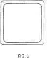
- Unitary hollow tube profiles like the one depicted in Fig. 1 , are known.
- the elongated tube may have a square cross-section, as shown, a circular cross-section, or any complex hollow profile.
- the hollow profile may be manufactured by extrusion, pultrusion, or other known manufacturing processes.
- the hollow tube profile may be made from any of a wide variety of known construction materials.
- production of fiber-reinforced hollow profiles using pultrusion presents manufacturing obstacles.
- the present invention overcomes those obstacles by pultruding fiber-reinforced, non-hollow rails that can then be assembled into complex hollow shapes that exhibit strength and stability on par with unity parts.
- Fig. 2 depicts a cross-section of an elongated snap tube 10 according to one embodiment of the invention.
- the hollow tube is formed from a first elongated rail 12 and a second elongated rail 14.
- the first rail 12 is formed with male and female snap members 16 and 18, respectively, that extend along the rail's entire length.
- an elongated hollow tube structure is formed.
- the square tube shown in Fig. 2 is only one embodiment.
- other hollow profiles including complex hollow shapes, can be formed using this process.
- each non-hollow rail may have only male or only female snap members.
- the hollow profile can be formed from three or more rails that are all joined together.
- each rail member is formed by a continuous pultrusion process that encapsulates continuous strands or mats of fiberglass within a polymeric resin such as polyurethane, polyester, vinyl ester or epoxy.
- a polymeric resin such as polyurethane, polyester, vinyl ester or epoxy.
- fiberglass includes not only glass fibers, but also carbon fibers, basalt fibers, and other reinforcing fibers such as Kevlar. Other materials and manufacturing processes can also be used to produce the non-hollow rails.
- two or more rail members are pultruded simultaneously and snapped together in a continuous, in-line fashion while the pultrusion is ongoing to produce a finished or near finished hollow tube assembly.
- Assembly of the snap together rails can be accomplished with or without adhesive depending on the level of structural integrity required by the functional specification.
- the assembled snap tube must function as one hollow shape, which requires significant strength and stability across the snap joints.
- a new snap geometry is employed that provides sufficient strength and other valuable benefits.
- Each snap configuration includes a mating male and female member.
- the female member is flexible and must elastically deform to engage with the male member.
- the male member is flexible and elastically deflects to engage with the female member.
- the male snap member 30 has a groove 32 along one side that provides an angled surface for reasons described further below.
- the groove 32 is a rounded recess that extends along the length of the male snap member 30.
- the groove 32 may be angular with flat sides. In each embodiment, however, the groove 32 provides an angled surface that is neither perpendicular nor parallel to the axis that runs from the base to the tip of the male snap member. In addition, the angled surface is neither perpendicular nor parallel to a direction in which the male snap member 30 is inserted into the female snap member 40.
- the female snap member 40 has two legs - a straight alignment leg 42 that serves to align the outer surfaces of two assembled rails, and a compression leg 44, which includes a foot 46 that is received in the groove 32 of the male snap member.
- a compression leg 44 which includes a foot 46 that is received in the groove 32 of the male snap member.
- elastic deformation of compression leg 44 results in a normal force exerted by the foot 46 in the groove 32.
- this force is exerted on an angled surface in the groove 32, it produces a component force along the direction of engagement that urges the male snap member 30 farther into the female snap member 40, clamping them together.
- This self-clamping feature of the new snap geometry eliminates the need for additional external clamping during the manufacturing process when adhesive is used in the snap joints.
- a first gap 48 and a second gap 50 are provided between the male and female snap members, even when fully assembled, where excess adhesive can accumulate rather than being forced out from between the snap to the exterior. This provides a cleaner appearance that more closely resembles a unitary piece rather than a two piece assembly. In some embodiments, only a single gap may be used. In other embodiments more than two gaps may be used. As shown in Fig. 7 , at least one gap may be provided directly adjacent to the straight alignment leg 42 of the female snap member where adhesive is most likely to be forced out of the joint.
- the male snap member 60 and female snap member 62 define an interior space 64 when they are engaged. When this space is filed with any substance that will harden, such as an adhesive, it will form a wedge or plug rendering the joint more or less permanently connected. This configuration provides additional mechanical strength and holding power over a joint that is merely adhered together.
Claims (4)
- Verfahren zur Fertigung einer Rohranordnung, die folgenden Schritte umfassend:Ziehen mindestens einer länglichen Schiene (12, 14), die ein aufzunehmendes Einrastelement (16, 20, 30, 60) aufweist, das sich entlang deren Länge erstreckt, wobei das aufzunehmende Einrastelement eine Nut (32) mit einer angewinkelten Fläche aufweist;Ziehen mindestens einer länglichen Schiene, die ein aufnehmendes Einrastelement (18, 22, 40, 62) aufweist, das sich entlang deren Länge erstreckt, wobei das aufnehmende Einrastelement einen ersten Schenkel (44) und einen zweiten Schenkel (42) umfasst, wobei der erste Schenkel flexibel ist und einen vorstehenden Fuß (46) aufweist, der dazu ausgelegt ist, in einer Nut eines entsprechenden aufzunehmenden Einrastelements aufgenommen zu werden und eine Kraft auf die angewinkelte Fläche der Nut aufzubringen; und ineinander Einrasten der länglichen Schienen, um eine hohle Rohranordnung auszubilden,dadurch gekennzeichnet, dass die Schritte des Ziehens mindestens einer länglichen Schiene, die ein aufzunehmendes Einrastelement aufweist, und des Ziehens der mindestens einen länglichen Schiene, die ein aufnehmendes Einrastelement aufweist, gleichzeitig durchgeführt werden, und wobei die Schienen während des Ziehvorgangs durchgehend ineinander eingerastet werden.
- Verfahren nach Anspruch 1, wobei die länglichen Schienen aus einem faserverstärkten Polymer bestehen.
- Verfahren nach Anspruch 1, ferner den Schritt des Aufbringens eines Klebstoffs auf das aufzunehmende Einrastelement und/oder das aufnehmende Einrastelement vor dem Schritt des ineinander Einrastens der länglichen Schienen umfassend.
- Verfahren nach Anspruch 1, wobei eine längliche Schiene, die ein aufzunehmendes Einrastelement aufweist, in eine längliche Schiene, die ein aufnehmendes Einrastelement aufweist, eingerastet wird, indem das aufzunehmende Einrastelement entlang einer ersten Richtung zwischen dem ersten und zweiten Schenkel des aufnehmenden Einrastelements eingesetzt wird und wobei die angewinkelte Fläche der Nut des aufzunehmenden Einrastelements weder parallel noch senkrecht zur ersten Richtung ist.
Priority Applications (2)
| Application Number | Priority Date | Filing Date | Title |
|---|---|---|---|
| PL17862057T PL3526416T3 (pl) | 2016-10-17 | 2017-10-16 | Zatrzaskowy zespół rurowy oraz sposób jego wytwarzania |
| EP21197740.0A EP3950286A1 (de) | 2016-10-17 | 2017-10-16 | Einrastbare rohranordnung und verfahren zur herstellung |
Applications Claiming Priority (2)
| Application Number | Priority Date | Filing Date | Title |
|---|---|---|---|
| US201662408997P | 2016-10-17 | 2016-10-17 | |
| PCT/US2017/056728 WO2018075377A1 (en) | 2016-10-17 | 2017-10-16 | Snap together tube assembly and manufacturing process |
Related Child Applications (1)
| Application Number | Title | Priority Date | Filing Date |
|---|---|---|---|
| EP21197740.0A Division EP3950286A1 (de) | 2016-10-17 | 2017-10-16 | Einrastbare rohranordnung und verfahren zur herstellung |
Publications (3)
| Publication Number | Publication Date |
|---|---|
| EP3526416A1 EP3526416A1 (de) | 2019-08-21 |
| EP3526416A4 EP3526416A4 (de) | 2020-06-24 |
| EP3526416B1 true EP3526416B1 (de) | 2021-09-22 |
Family
ID=61904426
Family Applications (2)
| Application Number | Title | Priority Date | Filing Date |
|---|---|---|---|
| EP17862057.1A Active EP3526416B1 (de) | 2016-10-17 | 2017-10-16 | Einrastbarer rohranordnung und verfahren zur herstellung |
| EP21197740.0A Pending EP3950286A1 (de) | 2016-10-17 | 2017-10-16 | Einrastbare rohranordnung und verfahren zur herstellung |
Family Applications After (1)
| Application Number | Title | Priority Date | Filing Date |
|---|---|---|---|
| EP21197740.0A Pending EP3950286A1 (de) | 2016-10-17 | 2017-10-16 | Einrastbare rohranordnung und verfahren zur herstellung |
Country Status (7)
| Country | Link |
|---|---|
| US (2) | US10451200B2 (de) |
| EP (2) | EP3526416B1 (de) |
| CN (2) | CN109963991B (de) |
| CA (2) | CA3039687C (de) |
| ES (1) | ES2901449T3 (de) |
| PL (1) | PL3526416T3 (de) |
| WO (1) | WO2018075377A1 (de) |
Families Citing this family (11)
| Publication number | Priority date | Publication date | Assignee | Title |
|---|---|---|---|---|
| US11364177B2 (en) * | 2016-08-03 | 2022-06-21 | Thomas Busch | Pressure equalizer for baby bottle and baby bottle assembly |
| JP6689762B2 (ja) * | 2017-01-11 | 2020-04-28 | 愛三工業株式会社 | 蒸発燃料処理装置 |
| CA3126938C (en) * | 2019-01-22 | 2024-01-16 | BendPak, Inc. | Three-level vehicle lift |
| US11715944B1 (en) | 2019-01-22 | 2023-08-01 | Titan3 Technology LLC | Expandable cord protector |
| DE202019101580U1 (de) * | 2019-03-20 | 2020-06-30 | Otto Fuchs - Kommanditgesellschaft - | Profilverbund |
| DE102019206852A1 (de) * | 2019-05-10 | 2020-11-12 | Volkswagen Aktiengesellschaft | Luftkanaleinrichtung und Kraftfahrzeug |
| CA3054121C (en) * | 2019-09-05 | 2022-05-03 | Thomas Fisher | Semi-rigid duct system |
| US11873161B2 (en) | 2020-04-30 | 2024-01-16 | Rubbermaid Commercial Products Llc | Waste receptacles |
| USD952981S1 (en) | 2020-04-30 | 2022-05-24 | Rubbermaid Commercial Products Llc | Waste receptacle with a handle |
| US11503883B1 (en) * | 2020-05-15 | 2022-11-22 | 3B International Pty Ltd | Band accessory |
| DE102021122153A1 (de) * | 2021-08-26 | 2023-03-02 | REHAU Industries SE & Co. KG | Verfahren zur Herstellung eines polymeren, insbesondere thermoplastischen Fenster- oder Tür-Hohlkammerprofils |
Family Cites Families (40)
| Publication number | Priority date | Publication date | Assignee | Title |
|---|---|---|---|---|
| US3757031A (en) * | 1972-05-02 | 1973-09-04 | Thomas & Betts Corp | The like selectively closable protective enclosure for electrical splices and |
| US3761603A (en) * | 1972-11-14 | 1973-09-25 | Amp Inc | Wiring raceway |
| US4019301A (en) | 1974-07-15 | 1977-04-26 | Fox Douglas L | Corrosion-resistant encasement for structural members |
| NL7811645A (nl) * | 1978-11-28 | 1980-05-30 | Stamicarbon | Deur, raam of kozijn. |
| SE420552B (sv) * | 1979-05-03 | 1981-10-12 | Ericsson Telefon Ab L M | Bandformig anordning for bildande av ett rorformigt teck- och skyddsholje |
| US4390164A (en) | 1981-09-23 | 1983-06-28 | Erden Cokelekoglu | Press lock system for railing construction |
| AU1834383A (en) * | 1982-08-31 | 1984-03-08 | Australian Plastic Mouldings Pty. Ltd. | Conduit |
| US4769963A (en) | 1987-07-09 | 1988-09-13 | Structural Panels, Inc. | Bonded panel interlock device |
| JPH0419938Y2 (de) * | 1987-12-17 | 1992-05-07 | ||
| US5007666A (en) * | 1990-01-19 | 1991-04-16 | C & L Development Inc. | Tongue and groove snap-fit pipe coupling |
| US5134250A (en) * | 1991-04-10 | 1992-07-28 | Panduit Corp. | Wiring duct |
| US5217771A (en) | 1991-04-17 | 1993-06-08 | Carsonite International Corp. | Sound barrier |
| US5343666A (en) | 1992-10-28 | 1994-09-06 | Ford Motor Company | Space frame joint construction |
| ES2092939B1 (es) | 1993-06-14 | 1997-06-16 | Aparellaje Electrico Sa | Dispositivo para el acoplamiento de canaletas para conducciones electricas. |
| US5462312A (en) * | 1994-06-23 | 1995-10-31 | Conducit Repair Systems, Inc. | Tubing coupling enclosure |
| BE1010487A6 (nl) * | 1996-06-11 | 1998-10-06 | Unilin Beheer Bv | Vloerbekleding bestaande uit harde vloerpanelen en werkwijze voor het vervaardigen van dergelijke vloerpanelen. |
| WO1998045915A1 (en) * | 1997-04-08 | 1998-10-15 | Zardoz Pty. Ltd. | Improvements in conduit systems |
| US6357196B1 (en) * | 1997-05-02 | 2002-03-19 | Mccombs M. Scott | Pultruded utility pole |
| CN2315686Y (zh) * | 1997-11-21 | 1999-04-21 | 萧子荣 | 高低边槽体反扣线槽 |
| KR100677757B1 (ko) * | 2000-12-01 | 2007-02-05 | 주식회사 케이티 | 통신구용 내관 |
| US6550819B2 (en) * | 2001-01-22 | 2003-04-22 | Aero Plumbing & Heating Co., Inc. | Pressure relieving arch having split pipe sleeves |
| US8028486B2 (en) * | 2001-07-27 | 2011-10-04 | Valinge Innovation Ab | Floor panel with sealing means |
| US7416227B1 (en) * | 2002-10-25 | 2008-08-26 | Earnest William C | Conduit repair apparatus and method |
| GB0321005D0 (en) * | 2003-09-09 | 2003-10-08 | Singleton Mark J | Structural couplings |
| US20050109415A1 (en) * | 2003-11-21 | 2005-05-26 | Snyder Darryl L. | Two piece air duct section |
| WO2005067544A2 (en) * | 2004-01-13 | 2005-07-28 | Composite Technology Corporation | Composite utility pole with implements for use in electrical distribution network |
| US8136324B2 (en) * | 2004-04-08 | 2012-03-20 | James M. Dombroski | Snap-fit pultrusion for housing elements |
| CN2800608Y (zh) * | 2005-02-07 | 2006-07-26 | 曹建辉 | 一种结构强度高的连体式电线线槽 |
| US20060185270A1 (en) | 2005-02-23 | 2006-08-24 | Gsw Inc. | Post trim system |
| US20070235212A1 (en) | 2006-04-05 | 2007-10-11 | Waldorf Heath A | Wiring harness |
| FR2901330B1 (fr) * | 2006-05-22 | 2010-10-29 | Saint Gobain | Systemes de connexion destines a equiper des plaques, notamment en verre, en vue de leur fixation et les plaques ainsi equipees |
| US20080148679A1 (en) | 2006-08-30 | 2008-06-26 | Gilbert Ray E | Synthetic-fiber reinforced window component |
| CN201155084Y (zh) * | 2008-02-05 | 2008-11-26 | 万水 | 一种拉挤树脂基纤维增强塑料型材 |
| US7784745B2 (en) * | 2008-06-02 | 2010-08-31 | Robert Dodge | Tube clip |
| US8302363B1 (en) | 2009-05-12 | 2012-11-06 | Ebert Composites Corporation | Composite interlocking structure |
| CN101591989B (zh) * | 2009-06-29 | 2011-10-12 | 南京工业大学 | 一种拉挤成型组装式复合材料电线杆 |
| US8183460B2 (en) | 2009-08-10 | 2012-05-22 | James Williams | Foldable raceway assembly |
| US9086057B2 (en) * | 2010-01-21 | 2015-07-21 | The Abell Foundation, Inc. | Ocean thermal energy conversion cold water pipe |
| CN202231373U (zh) * | 2011-08-11 | 2012-05-23 | 大连兴达玻璃钢有限公司 | 玻璃钢电线槽 |
| CN202454989U (zh) | 2012-02-08 | 2012-09-26 | 浙江飞龙管业有限公司 | 可分离式电力电缆护套管 |
-
2017
- 2017-10-16 EP EP17862057.1A patent/EP3526416B1/de active Active
- 2017-10-16 CA CA3039687A patent/CA3039687C/en active Active
- 2017-10-16 CN CN201780063983.5A patent/CN109963991B/zh active Active
- 2017-10-16 US US15/784,266 patent/US10451200B2/en active Active
- 2017-10-16 WO PCT/US2017/056728 patent/WO2018075377A1/en unknown
- 2017-10-16 CA CA3144936A patent/CA3144936A1/en active Pending
- 2017-10-16 ES ES17862057T patent/ES2901449T3/es active Active
- 2017-10-16 CN CN202011115381.XA patent/CN112554350A/zh active Pending
- 2017-10-16 EP EP21197740.0A patent/EP3950286A1/de active Pending
- 2017-10-16 PL PL17862057T patent/PL3526416T3/pl unknown
-
2019
- 2019-09-26 US US16/584,179 patent/US10995885B2/en active Active
Also Published As
| Publication number | Publication date |
|---|---|
| US20180106396A1 (en) | 2018-04-19 |
| WO2018075377A1 (en) | 2018-04-26 |
| PL3526416T3 (pl) | 2022-04-11 |
| CA3039687A1 (en) | 2018-04-26 |
| US10995885B2 (en) | 2021-05-04 |
| CA3144936A1 (en) | 2018-04-26 |
| CA3039687C (en) | 2022-03-01 |
| EP3526416A1 (de) | 2019-08-21 |
| CN109963991B (zh) | 2020-11-10 |
| CN109963991A (zh) | 2019-07-02 |
| US10451200B2 (en) | 2019-10-22 |
| US20200018430A1 (en) | 2020-01-16 |
| EP3950286A1 (de) | 2022-02-09 |
| ES2901449T3 (es) | 2022-03-22 |
| EP3526416A4 (de) | 2020-06-24 |
| CN112554350A (zh) | 2021-03-26 |
Similar Documents
| Publication | Publication Date | Title |
|---|---|---|
| EP3526416B1 (de) | Einrastbarer rohranordnung und verfahren zur herstellung | |
| US10920423B2 (en) | Method for producing a bar element | |
| US9068344B2 (en) | Method for incorporating thermal barriers into tubular extrusions using retainer clips | |
| CN104976500A (zh) | 用于连接空心型材的方法 | |
| US11034073B2 (en) | Method for forming inline triple wall coupling connector | |
| EP2214924B1 (de) | Verfahren zur herstellung einer führungsschiene und führungsschiene | |
| CN213075057U (zh) | 一种抗蠕变的装配式大幅面木塑拼板 | |
| WO2007118643A1 (de) | Verfahren zur herstellung eines formkörpers | |
| EP3398757B1 (de) | Verbundwelle | |
| CN219491694U (zh) | 装配式建筑模板及模板组件 | |
| CN220808594U (zh) | 一种复材管件的芯模组件 | |
| KR101905996B1 (ko) | 복합재 차체부품 및 그 제조방법 | |
| JP2681553B2 (ja) | 繊維強化樹脂製管状構造部材 | |
| WO2019079576A1 (en) | FLEXIBLE CONSTRUCTION SYSTEM WITH FRAME OF PULTRUDED MATERIAL | |
| KR100469377B1 (ko) | 곡면 건축 구조물 제작을 위한 임의의 곡률을 갖는복합재료 대구경 원관의 제작방법 | |
| CN114851598A (zh) | 带长内筋的多边形复材筒体抗压弯复合成型方法及生产线 | |
| EP2042288A1 (de) | Verbundkörper und Verfahren zu dessen Herstellung | |
| MX2013004803A (es) | Sistema constructivo a base tableros ligeros mejorados, con sistemas de ensamblaje y el proceso para su produccion. |
Legal Events
| Date | Code | Title | Description |
|---|---|---|---|
| STAA | Information on the status of an ep patent application or granted ep patent |
Free format text: STATUS: THE INTERNATIONAL PUBLICATION HAS BEEN MADE |
|
| PUAI | Public reference made under article 153(3) epc to a published international application that has entered the european phase |
Free format text: ORIGINAL CODE: 0009012 |
|
| STAA | Information on the status of an ep patent application or granted ep patent |
Free format text: STATUS: REQUEST FOR EXAMINATION WAS MADE |
|
| 17P | Request for examination filed |
Effective date: 20190513 |
|
| AK | Designated contracting states |
Kind code of ref document: A1 Designated state(s): AL AT BE BG CH CY CZ DE DK EE ES FI FR GB GR HR HU IE IS IT LI LT LU LV MC MK MT NL NO PL PT RO RS SE SI SK SM TR |
|
| AX | Request for extension of the european patent |
Extension state: BA ME |
|
| DAV | Request for validation of the european patent (deleted) | ||
| DAX | Request for extension of the european patent (deleted) | ||
| REG | Reference to a national code |
Ref country code: DE Ref legal event code: R079 Ref document number: 602017046534 Country of ref document: DE Free format text: PREVIOUS MAIN CLASS: E04B0001610000 Ipc: B29C0070520000 |
|
| A4 | Supplementary search report drawn up and despatched |
Effective date: 20200528 |
|
| RIC1 | Information provided on ipc code assigned before grant |
Ipc: B29K 75/00 20060101ALI20200520BHEP Ipc: F16B 5/12 20060101ALI20200520BHEP Ipc: B29L 31/00 20060101ALI20200520BHEP Ipc: B29C 70/52 20060101AFI20200520BHEP |
|
| GRAP | Despatch of communication of intention to grant a patent |
Free format text: ORIGINAL CODE: EPIDOSNIGR1 |
|
| STAA | Information on the status of an ep patent application or granted ep patent |
Free format text: STATUS: GRANT OF PATENT IS INTENDED |
|
| INTG | Intention to grant announced |
Effective date: 20210412 |
|
| GRAS | Grant fee paid |
Free format text: ORIGINAL CODE: EPIDOSNIGR3 |
|
| GRAA | (expected) grant |
Free format text: ORIGINAL CODE: 0009210 |
|
| STAA | Information on the status of an ep patent application or granted ep patent |
Free format text: STATUS: THE PATENT HAS BEEN GRANTED |
|
| AK | Designated contracting states |
Kind code of ref document: B1 Designated state(s): AL AT BE BG CH CY CZ DE DK EE ES FI FR GB GR HR HU IE IS IT LI LT LU LV MC MK MT NL NO PL PT RO RS SE SI SK SM TR |
|
| REG | Reference to a national code |
Ref country code: GB Ref legal event code: FG4D |
|
| REG | Reference to a national code |
Ref country code: IE Ref legal event code: FG4D |
|
| REG | Reference to a national code |
Ref country code: DE Ref legal event code: R096 Ref document number: 602017046534 Country of ref document: DE |
|
| REG | Reference to a national code |
Ref country code: CH Ref legal event code: EP Ref country code: AT Ref legal event code: REF Ref document number: 1431984 Country of ref document: AT Kind code of ref document: T Effective date: 20211015 |
|
| REG | Reference to a national code |
Ref country code: LT Ref legal event code: MG9D |
|
| REG | Reference to a national code |
Ref country code: NL Ref legal event code: MP Effective date: 20210922 |
|
| PG25 | Lapsed in a contracting state [announced via postgrant information from national office to epo] |
Ref country code: NO Free format text: LAPSE BECAUSE OF FAILURE TO SUBMIT A TRANSLATION OF THE DESCRIPTION OR TO PAY THE FEE WITHIN THE PRESCRIBED TIME-LIMIT Effective date: 20211222 Ref country code: BG Free format text: LAPSE BECAUSE OF FAILURE TO SUBMIT A TRANSLATION OF THE DESCRIPTION OR TO PAY THE FEE WITHIN THE PRESCRIBED TIME-LIMIT Effective date: 20211222 Ref country code: LT Free format text: LAPSE BECAUSE OF FAILURE TO SUBMIT A TRANSLATION OF THE DESCRIPTION OR TO PAY THE FEE WITHIN THE PRESCRIBED TIME-LIMIT Effective date: 20210922 Ref country code: RS Free format text: LAPSE BECAUSE OF FAILURE TO SUBMIT A TRANSLATION OF THE DESCRIPTION OR TO PAY THE FEE WITHIN THE PRESCRIBED TIME-LIMIT Effective date: 20210922 Ref country code: SE Free format text: LAPSE BECAUSE OF FAILURE TO SUBMIT A TRANSLATION OF THE DESCRIPTION OR TO PAY THE FEE WITHIN THE PRESCRIBED TIME-LIMIT Effective date: 20210922 Ref country code: HR Free format text: LAPSE BECAUSE OF FAILURE TO SUBMIT A TRANSLATION OF THE DESCRIPTION OR TO PAY THE FEE WITHIN THE PRESCRIBED TIME-LIMIT Effective date: 20210922 Ref country code: FI Free format text: LAPSE BECAUSE OF FAILURE TO SUBMIT A TRANSLATION OF THE DESCRIPTION OR TO PAY THE FEE WITHIN THE PRESCRIBED TIME-LIMIT Effective date: 20210922 |
|
| REG | Reference to a national code |
Ref country code: AT Ref legal event code: MK05 Ref document number: 1431984 Country of ref document: AT Kind code of ref document: T Effective date: 20210922 |
|
| PG25 | Lapsed in a contracting state [announced via postgrant information from national office to epo] |
Ref country code: LV Free format text: LAPSE BECAUSE OF FAILURE TO SUBMIT A TRANSLATION OF THE DESCRIPTION OR TO PAY THE FEE WITHIN THE PRESCRIBED TIME-LIMIT Effective date: 20210922 Ref country code: GR Free format text: LAPSE BECAUSE OF FAILURE TO SUBMIT A TRANSLATION OF THE DESCRIPTION OR TO PAY THE FEE WITHIN THE PRESCRIBED TIME-LIMIT Effective date: 20211223 |
|
| REG | Reference to a national code |
Ref country code: ES Ref legal event code: FG2A Ref document number: 2901449 Country of ref document: ES Kind code of ref document: T3 Effective date: 20220322 |
|
| PG25 | Lapsed in a contracting state [announced via postgrant information from national office to epo] |
Ref country code: AT Free format text: LAPSE BECAUSE OF FAILURE TO SUBMIT A TRANSLATION OF THE DESCRIPTION OR TO PAY THE FEE WITHIN THE PRESCRIBED TIME-LIMIT Effective date: 20210922 |
|
| REG | Reference to a national code |
Ref country code: CH Ref legal event code: PL |
|
| PG25 | Lapsed in a contracting state [announced via postgrant information from national office to epo] |
Ref country code: IS Free format text: LAPSE BECAUSE OF FAILURE TO SUBMIT A TRANSLATION OF THE DESCRIPTION OR TO PAY THE FEE WITHIN THE PRESCRIBED TIME-LIMIT Effective date: 20220122 Ref country code: SK Free format text: LAPSE BECAUSE OF FAILURE TO SUBMIT A TRANSLATION OF THE DESCRIPTION OR TO PAY THE FEE WITHIN THE PRESCRIBED TIME-LIMIT Effective date: 20210922 Ref country code: RO Free format text: LAPSE BECAUSE OF FAILURE TO SUBMIT A TRANSLATION OF THE DESCRIPTION OR TO PAY THE FEE WITHIN THE PRESCRIBED TIME-LIMIT Effective date: 20210922 Ref country code: PT Free format text: LAPSE BECAUSE OF FAILURE TO SUBMIT A TRANSLATION OF THE DESCRIPTION OR TO PAY THE FEE WITHIN THE PRESCRIBED TIME-LIMIT Effective date: 20220124 Ref country code: NL Free format text: LAPSE BECAUSE OF FAILURE TO SUBMIT A TRANSLATION OF THE DESCRIPTION OR TO PAY THE FEE WITHIN THE PRESCRIBED TIME-LIMIT Effective date: 20210922 Ref country code: EE Free format text: LAPSE BECAUSE OF FAILURE TO SUBMIT A TRANSLATION OF THE DESCRIPTION OR TO PAY THE FEE WITHIN THE PRESCRIBED TIME-LIMIT Effective date: 20210922 Ref country code: CZ Free format text: LAPSE BECAUSE OF FAILURE TO SUBMIT A TRANSLATION OF THE DESCRIPTION OR TO PAY THE FEE WITHIN THE PRESCRIBED TIME-LIMIT Effective date: 20210922 Ref country code: AL Free format text: LAPSE BECAUSE OF FAILURE TO SUBMIT A TRANSLATION OF THE DESCRIPTION OR TO PAY THE FEE WITHIN THE PRESCRIBED TIME-LIMIT Effective date: 20210922 |
|
| REG | Reference to a national code |
Ref country code: DE Ref legal event code: R097 Ref document number: 602017046534 Country of ref document: DE |
|
| PG25 | Lapsed in a contracting state [announced via postgrant information from national office to epo] |
Ref country code: MC Free format text: LAPSE BECAUSE OF FAILURE TO SUBMIT A TRANSLATION OF THE DESCRIPTION OR TO PAY THE FEE WITHIN THE PRESCRIBED TIME-LIMIT Effective date: 20210922 |
|
| PG25 | Lapsed in a contracting state [announced via postgrant information from national office to epo] |
Ref country code: DK Free format text: LAPSE BECAUSE OF FAILURE TO SUBMIT A TRANSLATION OF THE DESCRIPTION OR TO PAY THE FEE WITHIN THE PRESCRIBED TIME-LIMIT Effective date: 20210922 Ref country code: LU Free format text: LAPSE BECAUSE OF NON-PAYMENT OF DUE FEES Effective date: 20211016 |
|
| PLBE | No opposition filed within time limit |
Free format text: ORIGINAL CODE: 0009261 |
|
| STAA | Information on the status of an ep patent application or granted ep patent |
Free format text: STATUS: NO OPPOSITION FILED WITHIN TIME LIMIT |
|
| 26N | No opposition filed |
Effective date: 20220623 |
|
| PG25 | Lapsed in a contracting state [announced via postgrant information from national office to epo] |
Ref country code: LI Free format text: LAPSE BECAUSE OF NON-PAYMENT OF DUE FEES Effective date: 20211031 Ref country code: CH Free format text: LAPSE BECAUSE OF NON-PAYMENT OF DUE FEES Effective date: 20211031 |
|
| PG25 | Lapsed in a contracting state [announced via postgrant information from national office to epo] |
Ref country code: IE Free format text: LAPSE BECAUSE OF NON-PAYMENT OF DUE FEES Effective date: 20211016 |
|
| PG25 | Lapsed in a contracting state [announced via postgrant information from national office to epo] |
Ref country code: SI Free format text: LAPSE BECAUSE OF FAILURE TO SUBMIT A TRANSLATION OF THE DESCRIPTION OR TO PAY THE FEE WITHIN THE PRESCRIBED TIME-LIMIT Effective date: 20210922 |
|
| PGFP | Annual fee paid to national office [announced via postgrant information from national office to epo] |
Ref country code: FR Payment date: 20230125 Year of fee payment: 7 |
|
| PGFP | Annual fee paid to national office [announced via postgrant information from national office to epo] |
Ref country code: PL Payment date: 20230201 Year of fee payment: 6 Ref country code: BE Payment date: 20230127 Year of fee payment: 6 |
|
| PG25 | Lapsed in a contracting state [announced via postgrant information from national office to epo] |
Ref country code: CY Free format text: LAPSE BECAUSE OF FAILURE TO SUBMIT A TRANSLATION OF THE DESCRIPTION OR TO PAY THE FEE WITHIN THE PRESCRIBED TIME-LIMIT Effective date: 20210922 |
|
| PG25 | Lapsed in a contracting state [announced via postgrant information from national office to epo] |
Ref country code: SM Free format text: LAPSE BECAUSE OF FAILURE TO SUBMIT A TRANSLATION OF THE DESCRIPTION OR TO PAY THE FEE WITHIN THE PRESCRIBED TIME-LIMIT Effective date: 20210922 Ref country code: HU Free format text: LAPSE BECAUSE OF FAILURE TO SUBMIT A TRANSLATION OF THE DESCRIPTION OR TO PAY THE FEE WITHIN THE PRESCRIBED TIME-LIMIT; INVALID AB INITIO Effective date: 20171016 |
|
| PGFP | Annual fee paid to national office [announced via postgrant information from national office to epo] |
Ref country code: GB Payment date: 20231027 Year of fee payment: 7 |
|
| PGFP | Annual fee paid to national office [announced via postgrant information from national office to epo] |
Ref country code: ES Payment date: 20231102 Year of fee payment: 7 |
|
| PGFP | Annual fee paid to national office [announced via postgrant information from national office to epo] |
Ref country code: TR Payment date: 20231004 Year of fee payment: 7 Ref country code: IT Payment date: 20231023 Year of fee payment: 7 Ref country code: DE Payment date: 20231027 Year of fee payment: 7 |
|
| PGFP | Annual fee paid to national office [announced via postgrant information from national office to epo] |
Ref country code: PL Payment date: 20231004 Year of fee payment: 7 Ref country code: BE Payment date: 20231027 Year of fee payment: 7 |