EP3525910B1 - Filtereinrichtung und rundfilterelement, insbesondere zur gasfiltration - Google Patents
Filtereinrichtung und rundfilterelement, insbesondere zur gasfiltration Download PDFInfo
- Publication number
- EP3525910B1 EP3525910B1 EP17764825.0A EP17764825A EP3525910B1 EP 3525910 B1 EP3525910 B1 EP 3525910B1 EP 17764825 A EP17764825 A EP 17764825A EP 3525910 B1 EP3525910 B1 EP 3525910B1
- Authority
- EP
- European Patent Office
- Prior art keywords
- filter
- medium body
- flow
- filter medium
- filter element
- Prior art date
- Legal status (The legal status is an assumption and is not a legal conclusion. Google has not performed a legal analysis and makes no representation as to the accuracy of the status listed.)
- Active
Links
Images


Classifications
-
- B—PERFORMING OPERATIONS; TRANSPORTING
- B01—PHYSICAL OR CHEMICAL PROCESSES OR APPARATUS IN GENERAL
- B01D—SEPARATION
- B01D46/00—Filters or filtering processes specially modified for separating dispersed particles from gases or vapours
- B01D46/0002—Casings; Housings; Frame constructions
-
- B—PERFORMING OPERATIONS; TRANSPORTING
- B01—PHYSICAL OR CHEMICAL PROCESSES OR APPARATUS IN GENERAL
- B01D—SEPARATION
- B01D46/00—Filters or filtering processes specially modified for separating dispersed particles from gases or vapours
- B01D46/0039—Filters or filtering processes specially modified for separating dispersed particles from gases or vapours with flow guiding by feed or discharge devices
- B01D46/0041—Filters or filtering processes specially modified for separating dispersed particles from gases or vapours with flow guiding by feed or discharge devices for feeding
- B01D46/0045—Filters or filtering processes specially modified for separating dispersed particles from gases or vapours with flow guiding by feed or discharge devices for feeding by using vanes
-
- B—PERFORMING OPERATIONS; TRANSPORTING
- B01—PHYSICAL OR CHEMICAL PROCESSES OR APPARATUS IN GENERAL
- B01D—SEPARATION
- B01D46/00—Filters or filtering processes specially modified for separating dispersed particles from gases or vapours
- B01D46/24—Particle separators, e.g. dust precipitators, using rigid hollow filter bodies
- B01D46/2403—Particle separators, e.g. dust precipitators, using rigid hollow filter bodies characterised by the physical shape or structure of the filtering element
- B01D46/2411—Filter cartridges
- B01D46/2414—End caps including additional functions or special forms
-
- F—MECHANICAL ENGINEERING; LIGHTING; HEATING; WEAPONS; BLASTING
- F02—COMBUSTION ENGINES; HOT-GAS OR COMBUSTION-PRODUCT ENGINE PLANTS
- F02M—SUPPLYING COMBUSTION ENGINES IN GENERAL WITH COMBUSTIBLE MIXTURES OR CONSTITUENTS THEREOF
- F02M35/00—Combustion-air cleaners, air intakes, intake silencers, or induction systems specially adapted for, or arranged on, internal-combustion engines
- F02M35/02—Air cleaners
- F02M35/024—Air cleaners using filters, e.g. moistened
- F02M35/02475—Air cleaners using filters, e.g. moistened characterised by the shape of the filter element
- F02M35/02483—Cylindrical, conical, oval, spherical or the like filter elements; wounded filter elements
-
- B—PERFORMING OPERATIONS; TRANSPORTING
- B01—PHYSICAL OR CHEMICAL PROCESSES OR APPARATUS IN GENERAL
- B01D—SEPARATION
- B01D2201/00—Details relating to filtering apparatus
- B01D2201/04—Supports for the filtering elements
- B01D2201/0415—Details of supporting structures
-
- B—PERFORMING OPERATIONS; TRANSPORTING
- B01—PHYSICAL OR CHEMICAL PROCESSES OR APPARATUS IN GENERAL
- B01D—SEPARATION
- B01D2201/00—Details relating to filtering apparatus
- B01D2201/04—Supports for the filtering elements
- B01D2201/0415—Details of supporting structures
- B01D2201/0423—Details of supporting structures not in the inner side of the cylindrical filtering elements
-
- B—PERFORMING OPERATIONS; TRANSPORTING
- B01—PHYSICAL OR CHEMICAL PROCESSES OR APPARATUS IN GENERAL
- B01D—SEPARATION
- B01D2271/00—Sealings for filters specially adapted for separating dispersed particles from gases or vapours
- B01D2271/02—Gaskets, sealings
- B01D2271/022—Axial sealings
-
- B—PERFORMING OPERATIONS; TRANSPORTING
- B01—PHYSICAL OR CHEMICAL PROCESSES OR APPARATUS IN GENERAL
- B01D—SEPARATION
- B01D2275/00—Filter media structures for filters specially adapted for separating dispersed particles from gases or vapours
- B01D2275/20—Shape of filtering material
- B01D2275/201—Conical shape
-
- B—PERFORMING OPERATIONS; TRANSPORTING
- B01—PHYSICAL OR CHEMICAL PROCESSES OR APPARATUS IN GENERAL
- B01D—SEPARATION
- B01D2275/00—Filter media structures for filters specially adapted for separating dispersed particles from gases or vapours
- B01D2275/20—Shape of filtering material
- B01D2275/208—Oval shape
Definitions
- the invention relates to a filter device, in particular for gas filtration, according to the preamble of claim 1.
- DE 10 2004 053 118 A1 describes an air filter device for an internal combustion engine which has a hollow cylindrical filter element in a filter housing, the air to be cleaned flowing through the filter element radially from the inside to the outside.
- the air is passed into the interior of a filter medium body of the filter element via an open axial end face and flows through the wall of the filter medium body radially from the inside to the outside.
- the cleaned air is then discharged from the air filter device via an outlet nozzle.
- the filter element is placed on an inlet connector which is located on the bottom of the filter housing and, when installed, protrudes into the interior space in the filter element.
- the air to be introduced flows axially through the inlet connector into the interior space in the filter element and is then deflected in the radial direction to allow flow through the filter medium body.
- a hollow cylindrical filter element which has an inlet line on an end plate for supplying gas into the interior.
- the inlet line has at least one helical section on its inner wall, so that the gas flows out helically.
- WO 2009/012010 A1 describes a filter device with a filter head with opposite inlet and outlet and a filter housing with filter element attached to it, the filter element being designed with an inclined flange with an S-shaped cross section.
- the pressure loss is to be reduced by the diagonal through-opening with a non-flat surface.
- the invention is based on the object of designing a filter device with a round filter element, which has an internal flow space and through which fluid to be cleaned flows radially from the inside to the outside, with simple structural measures that a high filtration performance is given over a long operating period.
- the filter device has a round filter element and a filter housing for receiving the round filter element.
- the round filter element comprises a filter medium body, the wall of which the fluid to be cleaned can flow through in the radial direction in relation to the longitudinal axis of the filter medium body; furthermore, one end plate on each of the opposite end faces of the filter medium body.
- the raw side is located in an internal flow space in the filter medium body, and a support grid is arranged on the outer wall of the filter medium body.
- the filter housing comprises a housing cover which has a flow guide rib on an inside, which protrudes into the internal flow space of the round filter element.
- the filter housing includes a housing cover that can be placed on the filter base housing in order to close the receiving space in the filter base housing in which the filter element is inserted. Accordingly, a sword-shaped flow guide rib is arranged on the inside of the housing cover, which supports the introduction of the fluid flow into the internal flow space and the uniform particle loading of the filter element during the filtration of the fluid, especially with non-symmetrical or non-parallel flow conditions.
- the uncleaned fluid is directed from the outside radially in the direction of the filter medium body and then hits the flow guide rib on the inside of the housing cover, which influences the impinging fluid flow, for example divided into two and / or directed axially in the direction of the internal flow space of the filter medium body.
- the round filter element is designed in such a way that it has an open end disk which has a flow opening through which the flow guide rib protrudes, with over or through the flow opening the uncleaned fluid is introduced into the internal flow space in the filter medium body.
- the filter medium body can preferably be flowed through in the radial direction from the inside to the outside.
- a lateral flow opening which is designed as an inflow opening, is made in the housing cover.
- the inflow opening preferably corresponds to a further inflow opening which is introduced into the basic filter housing, in such a way that the inflow openings lie one above the other when the housing cover is in place.
- the flow guide rib can have a curvature, preferably such that a fluid flow introduced radially through the flow guide rib via the inflow opening of the housing cover experiences a deflection in the direction of the inner flow space of the filter medium body.
- a lateral inflow opening for the fluid to be introduced is advantageously also made in the basic filter housing of the filter housing, this inflow opening in the basic filter housing and the lateral inflow opening in the housing cover lying one above the other in the assembled state and forming a continuous flow path for the fluid introduced.
- the flow guide rib is either straight and lying in one plane or, according to an alternative embodiment, is curved. With a straight design, the flow guide rib can extend in the axial direction of the filter element, so that the wall sides of the flow guide rib run parallel to the longitudinal axis of the filter element.
- one end face of the flow guide rib faces the flow opening in the housing cover.
- the flow guide rib can in particular be arranged adjacent to the inflow opening in the housing cover, that is to say positioned in such a way that the end face of the flow guide rib faces the inflow opening in the housing cover.
- the fluid flow brought in radially via the housing cover hits the flow guide rib and is deflected in the direction of the internal flow space in the filter medium body.
- the flow guide rib and the inflow opening can also be aligned at least approximately parallel.
- a lateral outflow opening is made in the basic filter housing, through which the cleaned fluid flows out. It can be expedient for the outflow opening to be aligned at least approximately parallel to the inflow opening and to the flow guide rib.
- the filter element in the installed state protrudes slightly axially beyond the end face of the basic filter housing, which makes it easier to remove the filter element from the basic filter housing, for example for maintenance purposes.
- the seal carrier with the sealing element is at a small axial distance from the protruding face of the filter element and ensures the flow-tight separation between the outer section of the filter element and the inner section of the filter element accommodated in the basic filter housing.
- the filter device according to the invention with a round filter element is preferably used for gas filtration, for example for filtering air, in particular in the intake tract of an internal combustion engine of a vehicle.
- the filter element has an annularly closed filter medium body, the wall of which is flowed through by the fluid to be cleaned in the radial direction.
- the filter medium body encloses an internal flow space which is delimited by the inner wall of the filter medium body, the inner wall forming the raw side.
- the fluid to be cleaned is guided axially into the inner flow space and flows through the wall of the filter medium body in relation to its longitudinal axis in the radial direction.
- the outside of the filter medium body forms the clean side via which the cleaned fluid emerges from the wall of the filter medium body.
- the axial end faces of the filter medium body are covered in a flow-tight manner by end disks.
- One end plate has one with the inner one Central opening communicating with the flow space for the axial flow guidance of the fluid, the opposite end plate, on the other hand, is designed to be closed and tightly seals off the inner flow space axially to the outside.
- the end disk provided with the central opening on the filter element is expediently rounded on its radial inside, which facilitates the flow of the raw air into the interior space in the filter medium body. This is of particular importance when flowing into the interior of the filter element in order to minimize the total pressure loss if, as in the present case, the air preferably flows freely into the interior and, as further preferred, no flow pipe leading the air flow directly into the interior is provided.
- the radius of the rounding is advantageously greater on the radial inside of the end disk than on the radial outside. If necessary, the radius on the radial inside is made so large that the start of the radius on the end face is still within the contour of the filter medium body.
- the radius of the rounding on the radial inside of the end plate is, for example, in a range between 5 mm and 15 mm, e.g. 7.5 mm.
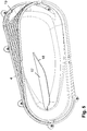
- the round filter element and the filter medium body can be designed as a hollow cylinder, so that the internal flow space is cylindrical. Furthermore, designs are possible in which the round filter element and the filter medium body are elongated and have an oval or oval cross-sectional shape. In the case of elongated cross-sectional shapes, cross-sectional shapes with parallel long sides and semicircular narrow sides are also possible. Furthermore, concave or convex longitudinal sides with radially inwardly directed bulges or radially outwardly directed bulges come into consideration.
- the inner wall and the outer wall of the filter medium body preferably run concentrically to one another, so that the filter medium body has a constant radial thickness.
- the inner wall and the outer wall of the filter medium body preferably run concentrically to one another, so that the filter medium body has a constant radial thickness.
- the round filter element has a cross-sectional shape that tapers in the axial direction so that the outer circumference of the round filter element in the area of the first end disk differs in size in comparison to the outer circumference of the round filter element in the area of the opposite, second end disk.
- round cross-sectional shapes in the area of both end disks come into consideration, so that the round filter element and the filter medium body are conical.
- the end plate can be designed to be closed on the end face with a smaller outer circumference and axially close the inner flow space, whereas the opposite end plate on the larger outer circumference has a flow opening for the introduction of fluid into the inner flow space.
- end plate is designed to be closed on the end face with a larger outer circumference and axially closes the inner flow space and the opposite end plate has a flow opening on the smaller outer circumference for introducing fluid into the inner flow space.
- the round filter element has a support grid on the outer wall of the filter medium body, which is designed in particular to be dimensionally stable.
- the support grid is designed, for example, as a thermoplastic injection-molded part. Due to the flow through the filter medium body radially from the inside to the outside, the wall of the filter medium body is subject to a pressure directed radially outward, under which the wall tends to curve outward.
- the support grid on the outer wall of the filter medium body prevents the wall from deforming radially outwards and thus holds the filter medium body in shape during the filtration so that deformation is avoided. Accordingly, the filter medium body retains its original geometric shape over a long period of operation, and the flow conditions are maintained during the filtration of the fluid.
- the filter medium body is supported on the outside by the support grid, so that the filter medium body is subjected to lower loads and the risk of damage to the filter medium body is reduced.
- at least one end face of the support grid is embedded in the end disks.
- At least one end plate is preferably made of a softer material than the support grid and a seal carrier on the filter element, which receives a sealing element.
- the end disk or the end disks are preferably made from a castable compound, such as, for example, and preferably polyurethane (PUR), in particular polyurethane foam.
- the filter medium body is preferably designed as a pleated filter with a plurality of filter pleats.
- the filter folds preferably run in or approximately in the radial direction and thus in the flow direction and at the same time extend axially between the two end faces of the filter medium body.
- the folded filter is designed to be closed in a ring shape.
- precisely one filter medium body designed as a round filter is arranged in the filter element.
- a shaped body protrudes into an end face of the filter medium body, which additionally stabilizes the filter medium body and, in the embodiment as a pleated filter, holds the filter folds in the desired position.
- the molded body is preferably located on the end face with a reduced cross-sectional area.
- the molded body can be formed in one piece with the support grid on the filter medium body, so that supporting forces acting on the end face of the filter element with the molded body are passed through the molded body to the supporting grid and the end plate is relieved of the supporting forces.
- the outer contour of the shaped body advantageously corresponds to the outer contour and / or the inner contour of the filter medium body on its end face, into which the shaped body protrudes into the filter medium body. It can be expedient to connect the shaped body at least in sections to the adjacent end disk, for example to form a dome on the shaped body which protrudes into the end disk.
- the end disk, into which one or more sections of the shaped body protrude, is preferably designed to be closed and seals the interior space in the filter medium body in a flow-tight manner.
- the shaped body can, if necessary, taper in a wedge shape towards its free end face, as a result of which the manufacturing process of the filter element is simplified and supported.
- the shaped body is designed and extends in particular as a longitudinally elongated body between opposite sides of the support grid.
- the round filter element has a sealing element, in particular a circumferential sealing ring, which is arranged on a seal carrier formed separately from the end plate and adjacent to the end plate on the raw air side, via which the uncleaned fluid is introduced into the inner flow space.
- the sealing element lies axially and radially at a distance from the adjacent, closest end plate. A flow-tight separation of the raw side from the clean side takes place via the sealing element. Due to the separate design of the seal carrier from the end disk, the end disk is not subject to the holding and sealing forces that are absorbed by the sealing element and the seal carrier when the round filter element is installed. The end disk thus remains unaffected by the holding and sealing forces.
- the seal carrier and sealing element are also at a distance from the clean or outside of the filter medium body, so that the fluid can escape unhindered from the seal carrier and the sealing element via the clean side of the filter medium body .
- the seal carrier is designed to be fluid-tight and advantageously connects the closest end disk to the sealing element in a fluid-tight manner.
- the seal carrier is axially spaced from the end face of the adjacent, closest end plate.
- the axial distance is, for example, based on the total axial height of the filter element, a maximum of 30% of the axial height, preferably a maximum of 20% of the axial height or a maximum of 10% of the axial height.
- the seal carrier is arranged on the support grid.
- a one-piece design of the support grid and seal carrier comes into consideration, which are preferably designed as plastic components.
- the sealing and holding as well as supporting forces are correspondingly absorbed via the seal carrier and the supporting grid, whereas the filter medium body is relieved of these forces.
- the seal carrier is designed as a circumferential carrier wall which extends at a distance from the outer jacket surface of the filter medium body.
- the carrier wall runs in particular parallel to the outer jacket surface of the filter medium body.
- the sealing element is advantageously inserted into a receiving groove in the carrier wall, the receiving groove preferably being on or adjacent to an end face of the carrier wall. The position of the sealing element on the support wall is on the end face of the support wall facing away from the nearest end plate.
- the seal carrier or the carrier wall in particular on the end face of the seal carrier or the carrier wall facing away from the sealing element, seals and preferably forms a positive fit with the end disk closest to the sealing element, ie. H. the open end disk, connected, in particular embedded in it or glued to it.
- the unit of seal carrier and support grille can advantageously be connected to both end plates, preferably by embedding the respective front ends in the respective end plate so that the end ends of the seal carrier and support grille are positively enclosed by the end plates.
- the seal carrier is advantageously supported on a housing component, for example on an internal shoulder in a filter base housing which accommodates the filter element and onto which a housing cover can be placed.
- nubs can optionally be formed, advantageously with an axial spacing from the end face.
- These knobs have the function of tolerance compensation and can compensate for deviations of the seal carrier from a flat surface for placing the housing cover and / or placing it on the shoulder in the basic filter housing.
- the knobs are, for example, rod-shaped and lie parallel to the side wall of the seal carrier; the rod-shaped knobs run, for example, in the radial direction. In the installed position, the knobs are pressed into the material of the housing component and / or the knobs are in particular elastic or plastic and deformed and thereby resemble Tolerance deviations.
- a softer material is preferably selected for the knobs than for the housing component (in particular the housing cover), so that the deformation takes place essentially or completely in the knobs.
- the smaller end plate has radially protruding support cams.
- These support cams advantageously do not protrude further in the radial direction than the opposite end disk or the inner or outer contour of the opposite seal.
- a slight overhang can also be provided in order to achieve a particularly strong tension.
- the inner contour of the seal carrier and / or the sealing element advantageously run in the radial direction essentially along the outer circumference of the larger end disk.
- the support cams are preferably located on the longitudinal sides and are in particular arranged on the end plate, preferably on the smaller end plate, in particular formed in one piece with the end plate and molded onto it.
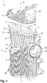
- a filter device 1 which is preferably used for gas filtration, in particular for air filtration in the intake tract of an internal combustion engine.
- the filter device 1 comprises a filter housing 2, which is composed of a filter base housing 3 and a housing cover 4, and a filter element 5 which can be inserted into the filter base housing 3.
- the housing cover 4 closes the receiving space in the basic filter housing for receiving the filter element 5.
- the filter element 5 is like that Fig. 1 , 3 and 4 can be seen, equipped with a filter medium body 6, on which the filtration of the fluid to be cleaned takes place.
- the filter element 5 is designed as a round filter element, and accordingly the filter medium body 6 is also designed as a round element which encloses an internal flow space 7 into which the fluid to be cleaned is introduced.
- the fluid is axially related to the longitudinal axis 8 of the filter element 5 and the filter device 1 ( Fig. 1 ), introduced into the flow space 7.
- the fluid then flows through the wall of the filter medium body 6 radially from the inside to the outside. Accordingly, the inner wall of the filter medium body 6 forms the raw side and the outer wall forms the clean side.
- the filter element 5 and the filter medium body 6 have a strongly ovalized shape with two parallel longitudinal sides and semicircular narrow sides.
- the filter element 5 has a conical basic shape, in which the axially opposite end faces of the filter element 5 are designed to be of different sizes and have an outer circumference of different sizes.
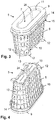
- the axial end faces of the filter medium body 6 are each covered in a flow-tight manner by an end plate 9, 10, the end plate 9 being open on the larger end face of the filter element 5 and having a flow opening 11 through which the raw fluid can flow into the internal flow space 7.
- the opposite end plate 10 is against how Fig. 4 to be taken, formed closed, so that the internal flow space 7 is axially closed on this side.
- Cams 12 are integrally formed on the closed end disk 10, which cams extend radially outward and are positioned on the longitudinal sides adjacent to the narrow sides.
- a support grid 13 which is made in particular from plastic and is formed separately from the end disks 9 and 10.
- the support grid 13 supports the filter medium body on its outer wall in the radial direction. Due to the radial flow through the filter medium body 6 from the inside to the outside, an outwardly directed pressure arises in the filter medium body, which is absorbed by the support grid 13. This ensures that the filter medium body 6 is not deformed by the pressure of the fluid flowing through it.
- the seal carrier 14 is designed as a circumferential carrier wall which lies in a plane orthogonal to the longitudinal axis 8 and is preferably made in one piece with the support grid 13.
- the seal carrier 14 is arranged at a small axial distance from the upper end disk 9 and at a considerably greater axial distance from the lower end disk 10.
- the outer circumference of the seal carrier 14 has a greater radial extent than the outer wall of the filter medium body 6.
- the sealing element 15 is designed as a sealing ring which is preferably inserted into a receiving groove in the end face of the support wall 14 on the side facing away from the adjacent end disk 9.
- the sealing element 15 faces away from the nearest end plate 9 and faces the opposite end plate 10 and, in the assembled state, lies on a circumferential shoulder 16 ( Fig. 1 ) on the inner wall of the receiving filter base housing 3.
- the shoulder 16 lies axially at a distance from the upper end edge of the basic filter housing 3.
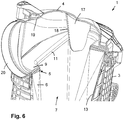
- the following statements refer to the housing cover 4, which has a sword-shaped flow guide rib 17 on its inside ( Fig. 5 , 6th , 7th ).
- the flow guiding rib 17 is in particular designed to be straight and lying in one plane and extends in the assembled state, such as Fig. 6 and 7th can be seen, axially into the internal flow space 7 in the filter element 5.
- the flow guide rib 17 is formed in one piece with the housing cover 4.
- a lateral inflow opening 19 is made in the housing cover 4, via which the raw fluid can flow radially into the filter device.
- the inflow opening 19 in the housing cover 4 corresponds to a further inflow opening 20 which is introduced into the filter base housing 3.
- the inflow openings 19 and 20 lie one above the other, so that a continuous flow path for the raw fluid is formed.
- the end face 18 of the flow guide rib 17 faces the inflow opening 19 in the housing cover 4.
- the flow guide rib 17 is located in the middle on the inside of the housing cover 4, so that the radially introduced raw fluid is divided by the sword-shaped flow guide rib 17 and also experiences an improved axial further flow in the direction of the internal flow space 7 in the filter medium body 6.
- Fig. 1 , 2 and 7th there is a lateral, radial outflow opening 21 on the basic filter housing 3 for the discharge of the cleaned fluid.
- the longitudinal axes of the flow of the inflow openings 19 and 20 on the one hand and the outflow opening 21 on the other hand run at least approximately parallel.
- the plane of the flow guide element 17 can also run at least approximately parallel to the longitudinal axes of the flow of inflow openings and outflow opening, although designs with a non-parallel arrangement of flow guide element 17 to openings 19, 20 and 21 as well as between inflow openings 19 and 20 and outflow opening 21 are also possible are.
- a molded body 22 which is in particular in one piece with the Support grid 13 is formed.
- the shaped body 22 protrudes axially into the inner flow space 7 in the filter medium body 6 and ensures a stabilization of the filter medium body 6 designed as a pleated filter protrudes into the lower end plate 10.
- the radially outer sections of the molded body 22 also protrude into the end plate 10, as a result of which a firm connection between the molded body 22 and the lower end plate 10 is achieved.
- the molded body 22 is at least essentially straight and extends in the longitudinal direction of the filter medium body 6.
- the radially outer sections of the molded body 22 are connected to the support grid 13 so that supporting and holding forces are absorbed by the molded body 22 and the lower end plate 10 is relieved becomes.
- annular support part 24 is formed centrally on the lower end disk 10 on the side axially facing away from the inner flow space 7, with which the filter element 5 can be placed on a support dome 25 on the housing side.
- the support dome 25 is located on the bottom of the filter base housing 3.
- the annular support part 24 has a longitudinally elongated cross-sectional shape.
- the inflow openings 19 and 20 are positioned in such a way that the end face of the upper end plate 9 forms a continuous contour at the same height with the inflow openings 19 and 20.
- the inner side of the inflow openings 19 and 20 lying at the bottom is axially at the same height as the outer end face of the overhead end disk 9. This ensures an unobstructed inflow of the raw fluid.
- the upper end disk 9 is provided on its radially inner side facing the central opening with a rounding 26 which facilitates the inflow of the raw fluid into the inner flow space 7.
- the radius of the rounding 26 on the radial inside of the end plate 9 is larger than on the radial outside of the end plate 9.
Landscapes
- Chemical & Material Sciences (AREA)
- Chemical Kinetics & Catalysis (AREA)
- Physics & Mathematics (AREA)
- Geometry (AREA)
- Engineering & Computer Science (AREA)
- Combustion & Propulsion (AREA)
- Mechanical Engineering (AREA)
- General Engineering & Computer Science (AREA)
- Filtering Of Dispersed Particles In Gases (AREA)
Priority Applications (1)
| Application Number | Priority Date | Filing Date | Title |
|---|---|---|---|
| EP21163762.4A EP3854470B1 (de) | 2016-10-17 | 2017-09-12 | Filtereinrichtung und rundfilterelement, insbesondere zur gasfiltration |
Applications Claiming Priority (2)
| Application Number | Priority Date | Filing Date | Title |
|---|---|---|---|
| DE102016012325.7A DE102016012325A1 (de) | 2016-10-17 | 2016-10-17 | Rundfilterelement, insbesondere zur Gasfiltration |
| PCT/EP2017/072836 WO2018072928A1 (de) | 2016-10-17 | 2017-09-12 | Filtereinrichtung und rundfilterelement, insbesondere zur gasfiltration |
Related Child Applications (1)
| Application Number | Title | Priority Date | Filing Date |
|---|---|---|---|
| EP21163762.4A Division EP3854470B1 (de) | 2016-10-17 | 2017-09-12 | Filtereinrichtung und rundfilterelement, insbesondere zur gasfiltration |
Publications (2)
| Publication Number | Publication Date |
|---|---|
| EP3525910A1 EP3525910A1 (de) | 2019-08-21 |
| EP3525910B1 true EP3525910B1 (de) | 2021-03-31 |
Family
ID=59846590
Family Applications (2)
| Application Number | Title | Priority Date | Filing Date |
|---|---|---|---|
| EP17764825.0A Active EP3525910B1 (de) | 2016-10-17 | 2017-09-12 | Filtereinrichtung und rundfilterelement, insbesondere zur gasfiltration |
| EP21163762.4A Active EP3854470B1 (de) | 2016-10-17 | 2017-09-12 | Filtereinrichtung und rundfilterelement, insbesondere zur gasfiltration |
Family Applications After (1)
| Application Number | Title | Priority Date | Filing Date |
|---|---|---|---|
| EP21163762.4A Active EP3854470B1 (de) | 2016-10-17 | 2017-09-12 | Filtereinrichtung und rundfilterelement, insbesondere zur gasfiltration |
Country Status (7)
| Country | Link |
|---|---|
| US (1) | US11117082B2 (pl) |
| EP (2) | EP3525910B1 (pl) |
| CN (1) | CN109803743B (pl) |
| DE (2) | DE102016012325A1 (pl) |
| ES (2) | ES2946711T3 (pl) |
| PL (1) | PL3854470T3 (pl) |
| WO (1) | WO2018072928A1 (pl) |
Families Citing this family (13)
| Publication number | Priority date | Publication date | Assignee | Title |
|---|---|---|---|---|
| WO2017092795A1 (fr) * | 2015-12-01 | 2017-06-08 | Ateliers Busch S.A. | Pompe a vide avec element filtrant |
| MX2020005694A (es) | 2017-12-08 | 2020-08-20 | Cummins Filtration Ip Inc | Sello ovalado con contorno de estabilizacion. |
| FR3078490B1 (fr) | 2018-03-05 | 2022-10-14 | Cummins Filtration Sarl | Element filtrant et boitier ayant des sections transversales non circulaires |
| US10918978B2 (en) | 2018-05-08 | 2021-02-16 | Cummins Filtration Ip, Inc. | Oval filter with exterior elliptical radial seal and internal support structure |
| USD884866S1 (en) | 2018-05-08 | 2020-05-19 | Cummins Filtration Ip, Inc. | Filter element |
| US11369908B2 (en) * | 2020-01-31 | 2022-06-28 | Pratt & Whitney Canada Corp. | Filter assembly for gas turbine engine |
| USD969289S1 (en) | 2020-03-05 | 2022-11-08 | Cummins Filtration Inc. | Filter element |
| DE102020116398B4 (de) | 2020-06-22 | 2025-09-04 | Mann+Hummel Gmbh | Filterelement, Gehäuse für ein Filtersystem und Filtersystem mit einem Filterelement und einem Gehäuse |
| US12161962B2 (en) * | 2020-10-28 | 2024-12-10 | Baldwin Filters, Inc. | Gasket and frame assembly for air filter |
| WO2022115423A1 (en) | 2020-11-24 | 2022-06-02 | Cummins Filtration Inc. | Arched air filter |
| CN115069035A (zh) * | 2022-06-29 | 2022-09-20 | 青海盐湖工业股份有限公司 | 模块化除尘装置 |
| US20250170511A1 (en) * | 2023-11-27 | 2025-05-29 | Caterpillar Inc. | Crankcase oil separation device for internal combustion engine |
| DE102024111993A1 (de) | 2024-04-29 | 2025-10-30 | Mann+Hummel Gmbh | Rundfilterelement, insbesondere zur Gasfiltration |
Family Cites Families (26)
| Publication number | Priority date | Publication date | Assignee | Title |
|---|---|---|---|---|
| FR1563990A (pl) | 1968-03-05 | 1969-04-18 | ||
| US5613992A (en) | 1994-11-23 | 1997-03-25 | Donaldson Company, Inc. | Reverse flow air filter arrangement and method |
| US5902364A (en) | 1996-04-26 | 1999-05-11 | Donaldson Company, Inc. | Conical filter |
| US5916435A (en) * | 1997-01-27 | 1999-06-29 | Porous Media Corporation | Conical coreless filter assembly and element |
| US6093237A (en) | 1998-06-04 | 2000-07-25 | Donaldson Company, Inc. | Stack filter assembly and methods |
| US6537339B2 (en) | 2001-05-04 | 2003-03-25 | Nelson Industries, Inc. | Moisture draining inside-out reverse flow air filter, mold and method |
| GB0217024D0 (en) * | 2002-07-23 | 2002-08-28 | Domnick Hunter Ltd | A coalescing filter element |
| JP4268016B2 (ja) | 2003-11-06 | 2009-05-27 | 本田技研工業株式会社 | エアクリーナ装置 |
| EP1621757B1 (en) * | 2004-07-29 | 2012-01-11 | Jui-Fa Huang | Vertical-shaft air filtering device having high flow rate and two-way air intake structure |
| GB0417459D0 (en) * | 2004-08-05 | 2004-09-08 | Domnick Hunter Ltd | Filter assembly |
| GB0417458D0 (en) * | 2004-08-05 | 2004-09-08 | Domnick Hunter Ltd | Filter assembly |
| GB0417464D0 (en) * | 2004-08-05 | 2004-09-08 | Domnick Hunter Ltd | Filter assembly |
| GB0417457D0 (en) * | 2004-08-05 | 2004-09-08 | Domnick Hunter Ltd | Filter element |
| US7413588B2 (en) * | 2004-11-24 | 2008-08-19 | Fleetguard, Inc. | High efficiency, low restriction, cost effective filter |
| US7618480B2 (en) * | 2007-07-16 | 2009-11-17 | Flair Corporation | Filter assembly and method |
| GB0715269D0 (en) * | 2007-08-04 | 2007-09-12 | Parker Hannifin Ltd | Filter assembly |
| GB0715247D0 (en) * | 2007-08-04 | 2007-09-12 | Parker Hannifin Ltd | Filter assembly |
| JP5635417B2 (ja) * | 2008-02-26 | 2014-12-03 | マン ウント フンメル ゲゼルシャフト ミット ベシュレンクテル ハフツング | 複数蛇腹フィルタ構成のフィルタエレメント |
| US20100155321A1 (en) * | 2008-12-23 | 2010-06-24 | Sasur Timothy M | Filter assembly |
| DE102009004909A1 (de) | 2009-01-16 | 2010-07-22 | Mahle International Gmbh | Luftfiltereinrichtung |
| DE102011011595A1 (de) * | 2011-02-17 | 2012-08-23 | Mann + Hummel Gmbh | Filterelement |
| DE102014006852B4 (de) * | 2013-06-20 | 2022-10-27 | Mann+Hummel Gmbh | Hohlfilterelement, Filtergehäuse und Filter |
| US10436155B2 (en) * | 2013-06-20 | 2019-10-08 | Mann+Hummel Gmbh | Air filter, filter element and filter housing of an air filter |
| PL3013456T3 (pl) * | 2013-06-28 | 2020-09-07 | Donaldson Company, Inc. | Wkład filtracyjny do zespołu filtra powietrza |
| DE102013218217A1 (de) * | 2013-09-11 | 2015-03-26 | Mahle International Gmbh | Luftfilter |
| FR3022152B1 (fr) * | 2014-06-17 | 2020-08-07 | Filtrauto | Filtre a carburant separateur d'eau et element filtrant avec detecteur d'eau. |
-
2016
- 2016-10-17 DE DE102016012325.7A patent/DE102016012325A1/de not_active Withdrawn
-
2017
- 2017-09-12 ES ES21163762T patent/ES2946711T3/es active Active
- 2017-09-12 WO PCT/EP2017/072836 patent/WO2018072928A1/de not_active Ceased
- 2017-09-12 ES ES17764825T patent/ES2867458T3/es active Active
- 2017-09-12 EP EP17764825.0A patent/EP3525910B1/de active Active
- 2017-09-12 PL PL21163762.4T patent/PL3854470T3/pl unknown
- 2017-09-12 CN CN201780064211.3A patent/CN109803743B/zh active Active
- 2017-09-12 EP EP21163762.4A patent/EP3854470B1/de active Active
- 2017-09-12 DE DE112017005243.2T patent/DE112017005243A5/de active Pending
-
2019
- 2019-04-17 US US16/386,384 patent/US11117082B2/en active Active
Non-Patent Citations (1)
| Title |
|---|
| None * |
Also Published As
| Publication number | Publication date |
|---|---|
| BR112019002427A2 (pt) | 2019-06-04 |
| DE112017005243A5 (de) | 2019-06-27 |
| US20190308123A1 (en) | 2019-10-10 |
| PL3854470T3 (pl) | 2023-08-07 |
| CN109803743A (zh) | 2019-05-24 |
| DE102016012325A1 (de) | 2018-04-19 |
| CN109803743B (zh) | 2021-11-02 |
| EP3525910A1 (de) | 2019-08-21 |
| US11117082B2 (en) | 2021-09-14 |
| EP3854470B1 (de) | 2023-04-19 |
| EP3854470A1 (de) | 2021-07-28 |
| ES2867458T3 (es) | 2021-10-20 |
| WO2018072928A1 (de) | 2018-04-26 |
| ES2946711T3 (es) | 2023-07-24 |
Similar Documents
| Publication | Publication Date | Title |
|---|---|---|
| EP3525910B1 (de) | Filtereinrichtung und rundfilterelement, insbesondere zur gasfiltration | |
| EP3525913B1 (de) | Rundfilterelement, insbesondere zur gasfiltration | |
| EP3525914B1 (de) | Luftfilterelement | |
| DE102016012328B4 (de) | Filtereinrichtung mit einem Rundfilterelement, insbesondere zur Gasfiltration | |
| EP3017854B1 (de) | Filter zur filtrierung von fluid | |
| EP2282825B1 (de) | Filtersystem | |
| EP3793711B1 (de) | Filterelement und filtersystem mit einem filterelement und einem gehäuse | |
| EP3452205B1 (de) | Filterelement, insbesondere zur gasfiltration, und filtereinrichtung | |
| WO2015193346A2 (de) | Filter und filtereinsatz | |
| WO2018072936A1 (de) | Rundfilterelement, insbesondere zur gasfiltration | |
| WO2014202450A1 (de) | Filterelement, filtergehäuse eines luftfilters und luftfilter | |
| WO2017190874A1 (de) | Ringförmiges filterelement, insbesondere zur gasfiltration | |
| EP4048424B1 (de) | Behandlungsvorrichtung zur behandlung von insbesondere flüssigen fluiden sowie behandlungseinheit und anschlusskopf für eine behandlungsvorrichtung | |
| WO2021063715A1 (de) | Flüssigkeitsfilter und volumenausgleichs-element für einen flüssigkeitsfilter | |
| EP4171781B1 (de) | Filtereinrichtung mit einem filterelement | |
| EP4017770B1 (de) | Rückschlagventil-vorrichtung | |
| EP4545163A2 (de) | Filter zur filtrierung von fluid, bypass-ventilanordnung für einen filter und diffusoreinrichtung für einen filter | |
| WO2025108671A1 (de) | Filterelement, insbesondere zur gasfiltration | |
| EP3297745B1 (de) | Filterelement, insbesondere zur gasfiltration | |
| DE112019002182B4 (de) | Rundfilterelement, insbesondere zur gasfiltration und filtereinrichtung | |
| DE102020115068A1 (de) | Filterelement, Dichtungsendscheibe eines Filterelements und Filter | |
| WO2025228621A1 (de) | Rundfilterelement, insbesondere zur gasfiltration | |
| WO2020020746A1 (de) | Filtereinsatz zum austauschbaren einbau in ein filtergehäuse eines filters für fluid und filter |
Legal Events
| Date | Code | Title | Description |
|---|---|---|---|
| STAA | Information on the status of an ep patent application or granted ep patent |
Free format text: STATUS: UNKNOWN |
|
| STAA | Information on the status of an ep patent application or granted ep patent |
Free format text: STATUS: THE INTERNATIONAL PUBLICATION HAS BEEN MADE |
|
| PUAI | Public reference made under article 153(3) epc to a published international application that has entered the european phase |
Free format text: ORIGINAL CODE: 0009012 |
|
| STAA | Information on the status of an ep patent application or granted ep patent |
Free format text: STATUS: REQUEST FOR EXAMINATION WAS MADE |
|
| 17P | Request for examination filed |
Effective date: 20190412 |
|
| AK | Designated contracting states |
Kind code of ref document: A1 Designated state(s): AL AT BE BG CH CY CZ DE DK EE ES FI FR GB GR HR HU IE IS IT LI LT LU LV MC MK MT NL NO PL PT RO RS SE SI SK SM TR |
|
| AX | Request for extension of the european patent |
Extension state: BA ME |
|
| DAV | Request for validation of the european patent (deleted) | ||
| DAX | Request for extension of the european patent (deleted) | ||
| STAA | Information on the status of an ep patent application or granted ep patent |
Free format text: STATUS: EXAMINATION IS IN PROGRESS |
|
| 17Q | First examination report despatched |
Effective date: 20200518 |
|
| GRAP | Despatch of communication of intention to grant a patent |
Free format text: ORIGINAL CODE: EPIDOSNIGR1 |
|
| STAA | Information on the status of an ep patent application or granted ep patent |
Free format text: STATUS: GRANT OF PATENT IS INTENDED |
|
| INTG | Intention to grant announced |
Effective date: 20201006 |
|
| GRAS | Grant fee paid |
Free format text: ORIGINAL CODE: EPIDOSNIGR3 |
|
| RIN1 | Information on inventor provided before grant (corrected) |
Inventor name: NEEF, PASCAL Inventor name: FRITZSCHING, TORSTEN Inventor name: WAGNER, FABIAN Inventor name: DONAUER, NADINE |
|
| GRAA | (expected) grant |
Free format text: ORIGINAL CODE: 0009210 |
|
| STAA | Information on the status of an ep patent application or granted ep patent |
Free format text: STATUS: THE PATENT HAS BEEN GRANTED |
|
| RAP1 | Party data changed (applicant data changed or rights of an application transferred) |
Owner name: MANN+HUMMEL GMBH |
|
| AK | Designated contracting states |
Kind code of ref document: B1 Designated state(s): AL AT BE BG CH CY CZ DE DK EE ES FI FR GB GR HR HU IE IS IT LI LT LU LV MC MK MT NL NO PL PT RO RS SE SI SK SM TR |
|
| REG | Reference to a national code |
Ref country code: GB Ref legal event code: FG4D Free format text: NOT ENGLISH Ref country code: CH Ref legal event code: EP |
|
| REG | Reference to a national code |
Ref country code: AT Ref legal event code: REF Ref document number: 1376287 Country of ref document: AT Kind code of ref document: T Effective date: 20210415 |
|
| REG | Reference to a national code |
Ref country code: DE Ref legal event code: R096 Ref document number: 502017009910 Country of ref document: DE |
|
| REG | Reference to a national code |
Ref country code: IE Ref legal event code: FG4D Free format text: LANGUAGE OF EP DOCUMENT: GERMAN |
|
| RAP4 | Party data changed (patent owner data changed or rights of a patent transferred) |
Owner name: MANN+HUMMEL GMBH |
|
| REG | Reference to a national code |
Ref country code: LT Ref legal event code: MG9D |
|
| PG25 | Lapsed in a contracting state [announced via postgrant information from national office to epo] |
Ref country code: BG Free format text: LAPSE BECAUSE OF FAILURE TO SUBMIT A TRANSLATION OF THE DESCRIPTION OR TO PAY THE FEE WITHIN THE PRESCRIBED TIME-LIMIT Effective date: 20210630 Ref country code: NO Free format text: LAPSE BECAUSE OF FAILURE TO SUBMIT A TRANSLATION OF THE DESCRIPTION OR TO PAY THE FEE WITHIN THE PRESCRIBED TIME-LIMIT Effective date: 20210630 Ref country code: FI Free format text: LAPSE BECAUSE OF FAILURE TO SUBMIT A TRANSLATION OF THE DESCRIPTION OR TO PAY THE FEE WITHIN THE PRESCRIBED TIME-LIMIT Effective date: 20210331 Ref country code: HR Free format text: LAPSE BECAUSE OF FAILURE TO SUBMIT A TRANSLATION OF THE DESCRIPTION OR TO PAY THE FEE WITHIN THE PRESCRIBED TIME-LIMIT Effective date: 20210331 |
|
| PG25 | Lapsed in a contracting state [announced via postgrant information from national office to epo] |
Ref country code: SE Free format text: LAPSE BECAUSE OF FAILURE TO SUBMIT A TRANSLATION OF THE DESCRIPTION OR TO PAY THE FEE WITHIN THE PRESCRIBED TIME-LIMIT Effective date: 20210331 Ref country code: LV Free format text: LAPSE BECAUSE OF FAILURE TO SUBMIT A TRANSLATION OF THE DESCRIPTION OR TO PAY THE FEE WITHIN THE PRESCRIBED TIME-LIMIT Effective date: 20210331 Ref country code: RS Free format text: LAPSE BECAUSE OF FAILURE TO SUBMIT A TRANSLATION OF THE DESCRIPTION OR TO PAY THE FEE WITHIN THE PRESCRIBED TIME-LIMIT Effective date: 20210331 |
|
| REG | Reference to a national code |
Ref country code: NL Ref legal event code: MP Effective date: 20210331 |
|
| REG | Reference to a national code |
Ref country code: ES Ref legal event code: FG2A Ref document number: 2867458 Country of ref document: ES Kind code of ref document: T3 Effective date: 20211020 |
|
| PG25 | Lapsed in a contracting state [announced via postgrant information from national office to epo] |
Ref country code: NL Free format text: LAPSE BECAUSE OF FAILURE TO SUBMIT A TRANSLATION OF THE DESCRIPTION OR TO PAY THE FEE WITHIN THE PRESCRIBED TIME-LIMIT Effective date: 20210331 Ref country code: SM Free format text: LAPSE BECAUSE OF FAILURE TO SUBMIT A TRANSLATION OF THE DESCRIPTION OR TO PAY THE FEE WITHIN THE PRESCRIBED TIME-LIMIT Effective date: 20210331 Ref country code: EE Free format text: LAPSE BECAUSE OF FAILURE TO SUBMIT A TRANSLATION OF THE DESCRIPTION OR TO PAY THE FEE WITHIN THE PRESCRIBED TIME-LIMIT Effective date: 20210331 Ref country code: CZ Free format text: LAPSE BECAUSE OF FAILURE TO SUBMIT A TRANSLATION OF THE DESCRIPTION OR TO PAY THE FEE WITHIN THE PRESCRIBED TIME-LIMIT Effective date: 20210331 Ref country code: LT Free format text: LAPSE BECAUSE OF FAILURE TO SUBMIT A TRANSLATION OF THE DESCRIPTION OR TO PAY THE FEE WITHIN THE PRESCRIBED TIME-LIMIT Effective date: 20210331 |
|
| PG25 | Lapsed in a contracting state [announced via postgrant information from national office to epo] |
Ref country code: RO Free format text: LAPSE BECAUSE OF FAILURE TO SUBMIT A TRANSLATION OF THE DESCRIPTION OR TO PAY THE FEE WITHIN THE PRESCRIBED TIME-LIMIT Effective date: 20210331 Ref country code: SK Free format text: LAPSE BECAUSE OF FAILURE TO SUBMIT A TRANSLATION OF THE DESCRIPTION OR TO PAY THE FEE WITHIN THE PRESCRIBED TIME-LIMIT Effective date: 20210331 Ref country code: PT Free format text: LAPSE BECAUSE OF FAILURE TO SUBMIT A TRANSLATION OF THE DESCRIPTION OR TO PAY THE FEE WITHIN THE PRESCRIBED TIME-LIMIT Effective date: 20210802 Ref country code: PL Free format text: LAPSE BECAUSE OF FAILURE TO SUBMIT A TRANSLATION OF THE DESCRIPTION OR TO PAY THE FEE WITHIN THE PRESCRIBED TIME-LIMIT Effective date: 20210331 Ref country code: IS Free format text: LAPSE BECAUSE OF FAILURE TO SUBMIT A TRANSLATION OF THE DESCRIPTION OR TO PAY THE FEE WITHIN THE PRESCRIBED TIME-LIMIT Effective date: 20210731 |
|
| REG | Reference to a national code |
Ref country code: DE Ref legal event code: R097 Ref document number: 502017009910 Country of ref document: DE |
|
| PG25 | Lapsed in a contracting state [announced via postgrant information from national office to epo] |
Ref country code: DK Free format text: LAPSE BECAUSE OF FAILURE TO SUBMIT A TRANSLATION OF THE DESCRIPTION OR TO PAY THE FEE WITHIN THE PRESCRIBED TIME-LIMIT Effective date: 20210331 Ref country code: AL Free format text: LAPSE BECAUSE OF FAILURE TO SUBMIT A TRANSLATION OF THE DESCRIPTION OR TO PAY THE FEE WITHIN THE PRESCRIBED TIME-LIMIT Effective date: 20210331 |
|
| PLBE | No opposition filed within time limit |
Free format text: ORIGINAL CODE: 0009261 |
|
| STAA | Information on the status of an ep patent application or granted ep patent |
Free format text: STATUS: NO OPPOSITION FILED WITHIN TIME LIMIT |
|
| 26N | No opposition filed |
Effective date: 20220104 |
|
| REG | Reference to a national code |
Ref country code: CH Ref legal event code: PL |
|
| REG | Reference to a national code |
Ref country code: BE Ref legal event code: MM Effective date: 20210930 |
|
| PG25 | Lapsed in a contracting state [announced via postgrant information from national office to epo] |
Ref country code: IS Free format text: LAPSE BECAUSE OF FAILURE TO SUBMIT A TRANSLATION OF THE DESCRIPTION OR TO PAY THE FEE WITHIN THE PRESCRIBED TIME-LIMIT Effective date: 20210731 Ref country code: MC Free format text: LAPSE BECAUSE OF FAILURE TO SUBMIT A TRANSLATION OF THE DESCRIPTION OR TO PAY THE FEE WITHIN THE PRESCRIBED TIME-LIMIT Effective date: 20210331 |
|
| PG25 | Lapsed in a contracting state [announced via postgrant information from national office to epo] |
Ref country code: LU Free format text: LAPSE BECAUSE OF NON-PAYMENT OF DUE FEES Effective date: 20210912 Ref country code: IT Free format text: LAPSE BECAUSE OF FAILURE TO SUBMIT A TRANSLATION OF THE DESCRIPTION OR TO PAY THE FEE WITHIN THE PRESCRIBED TIME-LIMIT Effective date: 20210331 Ref country code: IE Free format text: LAPSE BECAUSE OF NON-PAYMENT OF DUE FEES Effective date: 20210912 Ref country code: BE Free format text: LAPSE BECAUSE OF NON-PAYMENT OF DUE FEES Effective date: 20210930 |
|
| PG25 | Lapsed in a contracting state [announced via postgrant information from national office to epo] |
Ref country code: LI Free format text: LAPSE BECAUSE OF NON-PAYMENT OF DUE FEES Effective date: 20210930 Ref country code: CH Free format text: LAPSE BECAUSE OF NON-PAYMENT OF DUE FEES Effective date: 20210930 |
|
| PG25 | Lapsed in a contracting state [announced via postgrant information from national office to epo] |
Ref country code: CY Free format text: LAPSE BECAUSE OF FAILURE TO SUBMIT A TRANSLATION OF THE DESCRIPTION OR TO PAY THE FEE WITHIN THE PRESCRIBED TIME-LIMIT Effective date: 20210331 |
|
| P01 | Opt-out of the competence of the unified patent court (upc) registered |
Effective date: 20230601 |
|
| PG25 | Lapsed in a contracting state [announced via postgrant information from national office to epo] |
Ref country code: HU Free format text: LAPSE BECAUSE OF FAILURE TO SUBMIT A TRANSLATION OF THE DESCRIPTION OR TO PAY THE FEE WITHIN THE PRESCRIBED TIME-LIMIT; INVALID AB INITIO Effective date: 20170912 Ref country code: GR Free format text: LAPSE BECAUSE OF FAILURE TO SUBMIT A TRANSLATION OF THE DESCRIPTION OR TO PAY THE FEE WITHIN THE PRESCRIBED TIME-LIMIT Effective date: 20210331 |
|
| REG | Reference to a national code |
Ref country code: AT Ref legal event code: MM01 Ref document number: 1376287 Country of ref document: AT Kind code of ref document: T Effective date: 20220912 |
|
| PG25 | Lapsed in a contracting state [announced via postgrant information from national office to epo] |
Ref country code: AT Free format text: LAPSE BECAUSE OF NON-PAYMENT OF DUE FEES Effective date: 20220912 |
|
| PG25 | Lapsed in a contracting state [announced via postgrant information from national office to epo] |
Ref country code: MK Free format text: LAPSE BECAUSE OF FAILURE TO SUBMIT A TRANSLATION OF THE DESCRIPTION OR TO PAY THE FEE WITHIN THE PRESCRIBED TIME-LIMIT Effective date: 20210331 |
|
| PG25 | Lapsed in a contracting state [announced via postgrant information from national office to epo] |
Ref country code: MT Free format text: LAPSE BECAUSE OF FAILURE TO SUBMIT A TRANSLATION OF THE DESCRIPTION OR TO PAY THE FEE WITHIN THE PRESCRIBED TIME-LIMIT Effective date: 20210331 |
|
| PGFP | Annual fee paid to national office [announced via postgrant information from national office to epo] |
Ref country code: DE Payment date: 20250919 Year of fee payment: 9 |
|
| PGFP | Annual fee paid to national office [announced via postgrant information from national office to epo] |
Ref country code: GB Payment date: 20250919 Year of fee payment: 9 |
|
| PGFP | Annual fee paid to national office [announced via postgrant information from national office to epo] |
Ref country code: FR Payment date: 20250922 Year of fee payment: 9 |
|
| PG25 | Lapsed in a contracting state [announced via postgrant information from national office to epo] |
Ref country code: TR Free format text: LAPSE BECAUSE OF FAILURE TO SUBMIT A TRANSLATION OF THE DESCRIPTION OR TO PAY THE FEE WITHIN THE PRESCRIBED TIME-LIMIT Effective date: 20210331 |
|
| PGFP | Annual fee paid to national office [announced via postgrant information from national office to epo] |
Ref country code: ES Payment date: 20251030 Year of fee payment: 9 |