EP3525680B1 - Kernnadelbiopsiegerät zum sammeln einer vielzahl von proben mit einem einzigen stich - Google Patents
Kernnadelbiopsiegerät zum sammeln einer vielzahl von proben mit einem einzigen stich Download PDFInfo
- Publication number
- EP3525680B1 EP3525680B1 EP17791244.1A EP17791244A EP3525680B1 EP 3525680 B1 EP3525680 B1 EP 3525680B1 EP 17791244 A EP17791244 A EP 17791244A EP 3525680 B1 EP3525680 B1 EP 3525680B1
- Authority
- EP
- European Patent Office
- Prior art keywords
- piercer
- drive assembly
- assembly
- cutter
- lead screw
- Prior art date
- Legal status (The legal status is an assumption and is not a legal conclusion. Google has not performed a legal analysis and makes no representation as to the accuracy of the status listed.)
- Active
Links
Images


Classifications
-
- A—HUMAN NECESSITIES
- A61—MEDICAL OR VETERINARY SCIENCE; HYGIENE
- A61B—DIAGNOSIS; SURGERY; IDENTIFICATION
- A61B10/00—Instruments for taking body samples for diagnostic purposes; Other methods or instruments for diagnosis, e.g. for vaccination diagnosis, sex determination or ovulation-period determination; Throat striking implements
- A61B10/02—Instruments for taking cell samples or for biopsy
- A61B10/0233—Pointed or sharp biopsy instruments
- A61B10/0266—Pointed or sharp biopsy instruments means for severing sample
- A61B10/0275—Pointed or sharp biopsy instruments means for severing sample with sample notch, e.g. on the side of inner stylet
-
- A—HUMAN NECESSITIES
- A61—MEDICAL OR VETERINARY SCIENCE; HYGIENE
- A61B—DIAGNOSIS; SURGERY; IDENTIFICATION
- A61B10/00—Instruments for taking body samples for diagnostic purposes; Other methods or instruments for diagnosis, e.g. for vaccination diagnosis, sex determination or ovulation-period determination; Throat striking implements
- A61B10/02—Instruments for taking cell samples or for biopsy
- A61B2010/0208—Biopsy devices with actuators, e.g. with triggered spring mechanisms
-
- A—HUMAN NECESSITIES
- A61—MEDICAL OR VETERINARY SCIENCE; HYGIENE
- A61B—DIAGNOSIS; SURGERY; IDENTIFICATION
- A61B10/00—Instruments for taking body samples for diagnostic purposes; Other methods or instruments for diagnosis, e.g. for vaccination diagnosis, sex determination or ovulation-period determination; Throat striking implements
- A61B10/02—Instruments for taking cell samples or for biopsy
- A61B2010/0225—Instruments for taking cell samples or for biopsy for taking multiple samples
Definitions
- a biopsy is the removal of a tissue sample from a patient to enable examination of the tissue for signs of cancer or other disorders.
- Tissue samples may be obtained in a variety of ways using various medical procedures involving a variety of the sample collection devices.
- biopsies may be open procedures (surgically removing tissue after creating an incision) or percutaneous procedures (e.g. by fine needle aspiration, core needle biopsy, or vacuum assisted biopsy).
- the tissue sample is typically analyzed at a lab (e.g. a pathology lab, biomedical lab, etc.) that is set up to perform the appropriate tests (such as histological analysis).
- Biopsy samples have been obtained in a variety of ways in various medical procedures including open and percutaneous methods using a variety of devices. For instance, some biopsy devices may be fully operable by a user using a single hand, and with a single insertion, to capture one or more biopsy samples from a patient. In addition, some biopsy devices may be tethered to a vacuum module and/or control module, such as for communication of fluids (e.g., pressurized air, saline, atmospheric air, vacuum, etc.), for communication of power, and/or for communication of commands and the like. Other biopsy devices may be fully or at least partially operable without being tethered or otherwise connected with another device.
- fluids e.g., pressurized air, saline, atmospheric air, vacuum, etc.
- Other biopsy devices may be fully or at least partially operable without being tethered or otherwise connected with another device.
- One technique for collecting a breast biopsy is to use a core needle biopsy device.
- a core needle biopsy device is the MAX-CORE disposable core biopsy instrument manufactured by Bard Biopsy Systems.
- Core needle biopsy devices frequently use a sharp, solid piercer equipped with a lateral tissue receiving notch positioned adjacent to the distal end of the piercer. When tissue is received within the notch, an elongate hollow cutting sheath is translated over the notch to sever a tissue sample. The severed tissue sample is then stored within the notch until both the piercer and the cutting sheath are removed from the patient.
- core-needle biopsy devices only one tissue sample can be collected per insertion of the piercer and cutting sheath.
- Another technique for conducting a breast biopsy is to conduct a breast biopsy using a vacuum-assisted breast biopsy device.
- a current textbook in this area is " Vacuum-Assisted Breast Biopsy with Mammotome®” available November 11, 2012, copyright 2013 by Devicor Medical Germany GmBh, published in Germany by Springer Medizin Verlag, Authors: Markus Hahn, Anne Tardivon and Jan Casselman, ISBN 978-3-642-34270-7 .
- a hollow needle is used to penetrate tissue.
- the hollow needle includes a lateral aperture adjacent to a sharp distal tip.
- a hollow cutter is disposed within the hollow needle and is moved axially relative to the lateral aperture of the needle to sever tissue samples. Once a tissue sample is severed by the hollow cutter, the tissue sample is transported axially though the cutter and collected in a tissue collection feature.
- Exemplary core needle biopsy devices are disclosed in U.S. Pat. No. 5,560,373 , entitled “Needle Core Biopsy Instrument with Durable or Disposable Cannula Assembly,” issued on October 1, 1996; U.S. Pat. No. 5,817,033 , entitled “Needle Core Biopsy Device,” issued on October 6, 1998; U.S. Pat. No. 5,971,939 , entitled “Needle Core Biopsy Device,” issued on October 26, 1999; and U.S. Pat. No. 5,511,556 , entitled “Needle Core Biopsy Instrument,” issued on April 30, 1996.
- Document US 2011/054350 A1 describes a biopsy apparatus that includes a biopsy probe having a biopsy cannula and a sample basket arranged coaxially about a longitudinal axis.
- the sample basket is movably disposed relative to the biopsy cannula along the longitudinal axis from a tissue harvesting position to a tissue sample retrieval region.
- Document US 2002/065474 A1 describes a tissue sampling device for retrieving one or more tissue samples from a patient that is either handheld or mounted to a moveable carriage and advanced so that the needle tip is introduced into the patient.
- Document WO 2007/112751 A2 describes a biopsy device for harvesting at least one tissue sample from a body of a living being that comprises a hollow needle with an end portion adapted to be introduced into the body, and a cutting mechanism for severing the tissue sample.
- Biopsy devices may be used to collect tissue samples in a variety of ways. For example, in some instances tissue samples are collected into a single tissue basket such that all tissue samples collected during a given biopsy procedure are deposited into the single tissue sample basket. In some other instances, tissue samples are collected into a tissue sample holder having separate compartments for each collected tissue sample. Such a multicompartment tissue sample holder may additionally include trays or strips that individually hold each tissue sample separately from the other tissue samples. Such trays or strips may be removable or otherwise separable from the tissue sample holder at the conclusion of a biopsy procedure.
- tissue samples may be collected using biopsy devices under the guidance of various imaging modalities such as ultrasound image guidance, stereotactic (X-ray) guidance, MRI guidance, Positron Emission Mammography (“PEM” guidance), Breast-Specific Gamma Imaging (“BSGI”) guidance, or otherwise.
- imaging modalities such as ultrasound image guidance, stereotactic (X-ray) guidance, MRI guidance, Positron Emission Mammography (“PEM” guidance), Breast-Specific Gamma Imaging (“BSGI”) guidance, or otherwise.
- PET Positron Emission Mammography
- BSGI Breast-Specific Gamma Imaging
- the operator may position an ultrasound transducer on the patient's breast and maneuver the transducer while viewing an ultrasound image display screen to locate suspicious tissue in the patient's breast. Once the operator locates the suspicious tissue, the operator may anesthetize the target region of the breast. Once the breast has been anesthetized, the operator may create an initial incision using a scalpel at a location on the exterior of the breast offset from the transducer. A needle of a breast biopsy probe disposed coaxially within an introducer cannula is then inserted into the breast through the initial incision. The operator continues to hold the ultrasound transducer with one hand while maneuvering the biopsy probe with the other hand.
- the operator While viewing the ultrasound image on the display screen, the operator guides the needle to a position adjacent to the suspicious tissue.
- a cutter within the needle of the probe is used to remove tissue which is then conveyed either to a manual pick-up location on the breast biopsy device or to a tissue sample chamber.
- the needle of the breast biopsy device is then removed, leaving the introducer cannula disposed within the breast.
- the introducer cannula may then be used to introduce a biopsy marker cannula for deploying a biopsy site marker at the biopsy site. Once a marker has been deployed at the biopsy site, the biopsy marker cannula and the introducer cannula are both removed from the breast and the incision is closed using a medically acceptable way to close breaks in the skin.
- the patient is first positioned relative to x-ray equipment, which includes a breast localization assembly.
- x-ray equipment which includes a breast localization assembly.
- the patient is oriented in a prone position, with the patient lying face down on a procedure table with at least one breast hanging pendulously through an aperture in the procedure table.
- the breast is then compressed between a compression paddle and an x-ray receptor of a localization assembly that is positioned under the procedure table.
- a breast biopsy device is positioned on an automatic guide device in front of the compression paddle and between the breast and an x-ray source.
- a scout image is acquired with the x-ray receptor in a zero-degree angular position (i.e., the x-rays are emitted along an axis normal relative to the x-ray receptor). If the scout image indicates that the patient has been positioned in a desired position, the procedure may proceed with the acquisition of stereotactic image pairs. Stereotactic image pairs are acquired by orienting the x-ray source at various complementary angular positions relative to the x-ray receptor (e.g., +15° and -15°), with at least one x-ray image acquired at each position.
- an operator may identify a target site where biopsy sampling is desired by examining the stereotactic image pair.
- the target site is marked on each stereotactic image and a precise location of the target site on a Cartesian coordinate system is computed using an image processing module.
- the computed location of the target site is then communicated to the automatic guide device.
- the automatic guide device is responsive to this information to position the breast biopsy probe into a position that aligns with the target site. With the breast biopsy device positioned, an operator may then fire a needle of the biopsy probe into the breast of the patient, thereby positioning the needle at the target site.
- a cutter within the needle of the probe is used to remove tissue, which is then conveyed either to a manual pick-up location on the breast biopsy device or to a tissue sample chamber.
- a biopsy marker cannula is inserted into the needle and is used to deploy a biopsy site marker at the biopsy site. Once a marker has been deployed at the biopsy site, the needle is removed from the breast and the incision is closed using a medically acceptable way to close breaks in the skin.
- a targeting device e.g., a grid and cube combination or a pillar, post and cradle support combination
- a baseline MRI image is taken to verify the target location.
- a scalpel is used to incise the skin of the breast.
- an assembly formed by an obturator disposed in a sleeve, is inserted through the incision to penetrate the breast tissue under the skin.
- the obturator is removed and an imaging rod is inserted into the sleeve in place of the obturator.
- An imaging rod is defined simply as an appropriately shaped rod that includes a feature that is detectable by an imaging technique being used for the biopsy procedure.
- the MRI image of the imaging rod is used to locate the site to which the sleeve/obturator assembly has penetrated.
- the obturator cooperates with the breast tissue to provide a visually observable artifact in an MRI image. With both of these techniques, after the location within the breast where the biopsy is to be taken is confirmed, the obturator or the imaging rod is removed.
- the obturator or imaging rod is replaced in the sleeve with the needle of a breast biopsy probe.
- a cutter within the needle of the probe is used to remove tissue, which is then conveyed either to a manual pick up location on the breast biopsy device or to a breast biopsy device sample chamber.
- a biopsy marker cannula is inserted into the needle and is used to deploy a biopsy site marker at the biopsy site.
- the needle is then removed from the sleeve.
- the imaging rod or the obturator is put back into the breast for reimaging of the biopsy site. Then the imaging rod or obturator and the sleeve are removed.
- Vacuum assisted biopsy devices and core needle biopsy devices both may have various advantages over the other, depending on context.
- one advantage of vacuum assisted biopsy devices is that vacuum assistance permits removal of multiple tissue samples using a single insertion.
- core needle biopsy devices lack this feature, use of core needle biopsy devices may still be desirable.
- core needle biopsy devices are generally capable of having smaller needles relative to core needle biopsy devices, thereby reducing patient anxiety and increasing the capacity of the needle to penetrate a lesion. Therefore, in some instances it may be desirable to incorporate the feature of multiple sample removal of a vacuum assisted biopsy device into a core needle biopsy device to achieve the benefits present in both styles of biopsy device.
- a desirable feature of the device described herein, which is a core needle biopsy device is that the device allows for single insertion with multiple samples being obtained whilst using a core needle type device. Currently, it is believed that only vacuum assisted biopsy devices have this ability.
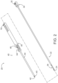
- FIGS. 1 shows an exemplary core needle biopsy device (10) for use in a breast biopsy procedure.
- Core needle biopsy device (10) of the present example comprises a body (12) and a needle assembly (20) extending distally from body (12).
- Body (12) includes an outer housing (14) and an actuation member (16) disposed on outer housing (14).
- outer housing (14) encloses various components of biopsy device (10), which are used to drive needle assembly (20) through a cutting cycle and a tissue acquisition cycle.
- outer housing (14) of the present example is sized and shaped for grasping by an operator using a single hand.
- outer housing (14) may comprise multiple parts such that each part interconnects to form outer housing (14).
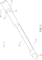
- FIGS. 2 and 3 show needle assembly (20) in greater detail.
- needle assembly (20) comprises an elongate piercer (22) and an elongate cutter (40).
- piercer (22) is generally movable relative to cutter (40) to pierce tissue and collect tissue samples, while cutter is generally movable relative to piercer (22) to sever tissue samples.
- Piercer (22) comprises a generally cylindrical rod having a sharp distal tip (24) and a notch (26) disposed adjacent to distal tip (24).
- distal tip (24) is generally configured to penetrate tissue of a patient.
- notch (26) is generally configured to receive tissue therein such that a tissue sample may be collected within notch (26) after the tissue sample is severed by cutter (40).
- An end portion (30) is disposed on the proximal end of piercer (22).
- End portion (30) of the present example is overmolded onto the proximal end of piercer (22) and is generally configured to enhance the manipulability of piercer (22).
- end portion (30) comprises a receiving feature (32) in the form of a lateral notch.
- Receiving feature (32) is configured to receive a portion of a piercer drive assembly (300). As will be described in greater detail below, this permits piercer drive assembly (300) to drive movement of piercer (22) through a predetermined sequence of movement.
- Cutter (40) comprises a generally hollow cylindrical tube that is configured to receive piercer (22) therein.
- Cutter (40) comprises an open distal end (42), a cannula portion (44) and an end portion (50).
- Open distal end (42) is configured to permit at least a portion of piercer (22) to protrude from cutter (40) when piercer (22) is moved relative to cutter (40).
- this configuration permits needle assembly (20) to move through the cutting cycle and the tissue acquisition cycle by permitting notch (26) of piercer (22) to move relative to distal end (42) of cutter (40).
- Open distal end (42) of the present example includes a tapered edge (43).
- Tapered edge (43) is generally configured to slice through tissue to separate tissue samples when cutter (40) is moved relative to notch (26) of piercer (22).
- tapered edge (43) is generally configured to act a blade.
- tapered edge (43) includes a plurality of serrations in addition or in alternative to the taper shown.
- tapered edge (43) can include any other additional or alternative cutting surface as will be apparent to those of ordinary skill in the art in view of the teachings herein.
- Cannula portion (44) of cutter (40) extends proximally from distal end (42) through end portion (50) such that piercer (22) can be received with the proximal end of cutter (40).
- end portion (50) of cutter (40) is generally elongate such that at least a portion of end portion (50) extends distally relative to outer housing (14). As will be described in greater detail below, this distal extension relative to outer housing (14) permits a portion of end portion (50) to be accessible to an operator for tissue sample collection purposes.
- End portion (50) of cutter (40) comprises a receiving feature (52) and a tissue collection feature (54).
- receiving feature (52) of end portion (50) comprises a lateral slot or other receiving feature that is configured to receive at least a portion of a cutter drive assembly (200).
- receiving feature (52) is configured to receive at least a portion of cutter drive assembly (200) to permit cutter drive assembly (200) to move cutter (40) through a predetermined sequence of movement.
- Tissue collection feature (54) is disposed distally relative to receiving feature (52).
- Tissue collection feature (54) generally defines an elongate notch that is open to cannula portion (44) of cutter (40).
- cannula portion (44) includes a cutout portion (46) that is adjacent to tissue collection feature (54).
- tissue collection feature (54) is in communication with the hollow interior, or a lumen, defined by cannula portion (44). As will be described in greater detail below, this relationship between tissue collection feature (54) and cannula portion (44) permits an operator to remove tissue samples from cutter (40) as they are collected by piercer (22).
- FIG. 3 shows piercer (22) disposed within cutter (40).
- cutter (40) is generally configured to receive piercer (22) such that piercer (22) is coaxial with cutter (40).
- piercer (22) is generally movable relative to open distal end (42) of cutter (40). It should be understood that in some circumstances piercer (22) moves relative to cutter (40), while cutter (40) remains stationary. In other circumstances, cutter (40) moves relative to piercer (22), while piercer (22) remains stationary.
- piercer (22) and cutter (40) are generally configured such that notch (26) of piercer (22) moves into and out of cutter (40) such that notch (26) can be disposed distally or proximally relative to open distal end (42) of cutter (40).
- this configuration permits piercer (22) and cutter (40) to operate cooperatively to pierce tissue, cut a tissue sample, and retract the tissue sample for collection by an operator via tissue collection feature (54).
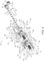
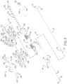
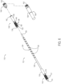
- FIGS. 4 and 5 show the internal components of body (12) of biopsy device (10) with outer housing (14) removed.
- body (12) includes a drive assembly (100).
- Drive assembly (100) is generally configured to engage needle assembly (20) to drive piercer (22) and cutter (40) through a predetermined sequence of movements to thereby pierce tissue and acquire a plurality of tissue samples with a single insertion of needle assembly (20) into a patient.
- outer housing (14) defines various internal geometries that support or otherwise engage drive assembly (100). As will be understood, such internal geometries are used to provide relative movement of various components of drive assembly (100) relative to other components of drive assembly (100) and/or outer housing (14).
- Drive assembly (100) comprises a needle cocking assembly (110), a cutter drive assembly (200), a piercer drive assembly (300), and a release assembly (400).
- needle cocking assembly (110) engages cutter drive assembly (200) and piercer drive assembly (300) to cock cutter drive assembly (200) and piercer drive assembly (300), which correspondingly cock cutter (40) and piercer (22).
- Release assembly (400) also engages cutter drive assembly (200) and piercer drive assembly (300) to selectively release and fire cutter drive assembly (200) and piercer drive assembly (300) to thereby selectively release and fire cutter (40) and piercer (22).
- Needle cocking assembly (110) is best seen in FIGS. 6-9 .
- needle cocking assembly (110) comprises a lead screw (112), a carriage nut (130), a drive member (150), and a motor assembly (160).
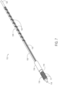
- Lead screw (112) is best seen in FIG. 7 .
- lead screw (112) is generally an elongate multi-threaded rod.
- Lead screw (112) comprises a distal end (114), first threaded portion (116), a slide stop portion (118), a non-threaded portion (120), a keyway (122), a second threaded portion (124), and a proximal end (126).
- Distal end (114) of lead screw (112) generally comprises a cylindrical shape extending distally from first threaded portion (116). Distal end (114) is configured to be received by at least a portion of outer housing (14) or another intermediate connecting member, such as a bearing, to permit lead screw (112) to rotate about a fixed axis. Thus, it should be understood that distal end (114) generally acts as a boss or locating feature to permit rotation of lead screw (112).
- First threaded portion (116) is disposed proximally of distal end (114).
- First threaded portion (116) includes threads (117) which have a relatively fine pitch.
- threads (117) are generally configured to engage a portion of cutter drive assembly (200) to convert rotational motion of lead screw (112) into translation of at least a portion of cutter drive assembly (200). This conversion of motion generally results in proximal and distal translation of at least a portion of cutter drive assembly (200), which results in cocking of cutter drive assembly (200).
- Slide stop portion (118) is disposed proximally of first threaded portion (116) and distally of keyway (122), second threaded portion (124) and proximal end (126).
- Slide stop portion (118) comprises a generally cylindrical shape.
- the diameter of slide stop portion (118) generally corresponds to the major pitch diameter of first threaded portion (116).
- these size and shape characteristics of slide stop portion (118) permit slide stop portion (118) to provide coaxial support of at least a portion of cutter drive assembly (200) as cutter drive assembly (200) moves relative to lead screw (112).
- slide stop portion (118) is also generally greater than the diameter of non-threaded portion (120) of lead screw (112). As will be understood, this differential in diameter between slide stop portion (118) and non-threaded portion (120) permits slide stop portion (118) to act as a mechanical stop feature. As will be described in greater detail below, this mechanical stop feature is configured to limit distal translation of carriage nut (130) as carriage nut (130) moves along lead screw (112).
- indented portion (119) is generally configured to permit a portion of cutter drive assembly (200) to "free-wheel” when cutter drive assembly (200) is disposed in axial alignment with indented portion (119). It should be understood that the term "free-wheel” used herein refers to the ability of lead screw (112) to continue to rotate without additional proximal translation of cutter drive assembly (200) and without binging between lead screw (112) and at least a portion of cutter drive assembly (200).
- cutter drive assembly (200) is generally disengaged from first threaded portion (116) of lead screw (112).
- the length of indented portion (119) is sufficiently limited such that when rotation of lead screw (112) is reversed, at least a portion of cutter drive assembly (200) reengages with first threaded portion (116) of lead screw (112). Further details of the relationship between indented portion (119), first threaded portion (116) and cutter drive assembly (200) will be described in greater detail below.
- non-threaded portion (120) is proximally adjacent to slide stop portion (118).
- Non-threaded portion (120) is also distally adjacent to second threaded portion (124) and is disposed distally of proximal end (126).
- Non-threaded portion (120) is generally of a cylindrical shape without threads or other features.
- keyway (122) extends through non-threaded portion (120) and through second threaded portion (124).
- non-threaded portion (120) has a diameter that is generally less than the diameter defined by slide stop portion (118).
- this differential in diameter between non-threaded portion (120) and slide stop portion (118) permits non-threaded portion (120) to provide a mechanical stop feature for carriage nut (130), as will be described in greater detail below.
- Second threaded portion (124) is disposed between non-threaded portion (120) and proximal end (126), with non-threaded portion (120) distal of second threaded portion (124) and proximal end (126) proximal of non-threaded portion (120).
- Second threaded portion (124) includes a plurality of relatively course threads (125). Threads (125) are generally course relative to threads (117) of first threaded portion (116). Thus it should be understood that with both threads (125, 117) acting to transfer rotary movement into axial translation, threads (125) of second threaded portion (124) will generally provide faster translation from the same rotary input relative to threads (117) of first threaded portion (116).
- Second threaded portion (124) of the present example is configured to engage at least a portion of piercer drive assembly (300).
- threads (125) of second threaded portion (124) are generally configured to convert rotatory motion of lead screw (112) into axial translation of at least a portion of piercer drive assembly (300). This conversion of rotary motion into translation permits piercer drive assembly to translate piercer (22) for the purpose of tissue collection via tissue collection feature (54).
- second threaded portion (124) and non-threaded portion (120) are arranged such that non-threaded portion (120) defines a length.
- the length of non-threaded portion (120) is generally just greater than the approximate length of carriage nut (130).
- the length of non-threaded portion permits carriage nut (130) to be axially translated by piercer drive assembly (300) until being stopped by slide stop portion (120). Once translation is ceased by slide stop portion (120), however, non-threaded portion (120) permits lead screw (112) to "free-wheel” relative to piercer drive assembly (300).
- free-wheel refers to the ability of lead screw (112) to continue to rotate without additional translation of piercer drive assembly (300) and without binding between lead screw (112) and piercer drive assembly (300).
- piercer drive assembly (300) generally disengaged from second threaded portion (124).
- the length of non-threaded portion remains limited to an extent such that when rotation of lead screw (112) is reversed, piercer drive assembly (300) reengages with second threaded portion (124). Further details of the relationship between non-threaded portion (120), second threaded portion (124) and piercer drive assembly (300) will be described in greater detail below.
- drive member (150) and motor assembly (160) rotation of lead screw (112) is provided by drive member (150) and motor assembly (160).
- drive member (150) of the present example is configured to be fixedly secured to proximal end (126) of lead screw (112).
- Drive member (150) includes a rotary communication feature (152) which is configured to transmit rotary motion from a rotary communication feature (162) of motor assembly (160) to lead screw (112).
- rotatory communication features (152, 162) are configured as belt drives such that rotatory motion is communicated via a belt (not shown). It should be understood that although rotary communication features (152, 162) are shown as using a belt drive, any other suitable rotary communication feature may be used.
- rotary communication features (152, 162) can include one or more gears with varying gear ratios to communicate rotary motion from motor assembly (160) to lead screw (112).
- rotary communication features (152, 162) can be omitted entirely such that motor assembly (160) includes a direct drive that directly communicates rotary motion to lead screw (112).
- motor assembly (160) includes a rotary communication feature (162). Additionally, motor assembly (160) includes a rotary power source (164).
- Rotary power source (164) of the present example includes an electric motor. In other examples, rotary power source (164) may include any other suitable power source such as a pneumatic motor, a piezo electric motor, and/or etc.
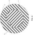
- FIG. 8 shows carriage nut (130) in greater detail.
- carriage nut (130) comprises a generally cylindrical shape with a bore (132) extending entirely therethough. Extending inwardly into bore (132) is a key (134). Key (134) extends axially through at least a portion of the length of carriage nut (130). As will be described in greater detail below, key (134) is generally configured to engage keyway (122) of lead screw (112) such that carriage nut (130) is generally configured to rotate in conjunction with lead screw (112).
- Threaded portion (136) includes a plurality of threads (138).
- Threads (138) generally include a pitch that is relatively fine and generally equivalent to the pitch of threads (117) of first threaded portion (116) described above with respect to lead screw (112).
- threads (138) of threaded portion (136) are generally configured to engage at least a portion of piercer drive assembly (300) to move at least a portion of piercer drive assembly (300) thorough a variety of positions to thereby cock and fire piercer (22).
- Slide portion (140) defines a generally cylindrical shape having an outer diameter.
- the outer diameter of slide portion (140) approximately corresponds to the major diameter of threaded portion (136). As will be described in greater detail below, this correspondence in diameters permits at least a portion of cutter drive assembly (200) to freely slide over both slide portion (140) and threaded portion (136), while remaining generally coaxial with carriage nut (130).
- annular channel (142) Adjacent to the proximal end of carriage nut (130), slide portion (140) defines an annular channel (142).
- annular channel (142) is configured to receive at least a portion of piercer drive assembly (300) to axially secure at least a portion of piercer drive assembly (300) to carriage nut (130).
- any portion of cutter drive assembly (300) axially secured to carriage nut (130) via cannula channel (142) is rotatably unsecured such that carriage nut (130) can rotate relative to piercer drive assembly (300).
- carriage nut (130) Disposed between slide portion (140) and threaded portion (136), carriage nut (130) defines an indented portion (144).
- Indented portion (144) is defined by an outer diameter that is generally less than the major diameter of threaded portion (136) and the outer diameter of slide portion (140).
- indented portion (144) defines a length. As will be described in greater detail below, the length of indented portion (144) is generally approximately equivalent to at least a portion of piercer drive assembly (300) to permit a portion of piercer drive assembly (300) to free-wheel relative to carriage nut (130).
- indented portion (144) is generally configured to permit a portion of piercer drive assembly (300) to free-wheel when piercer drive assembly (300) is disposed in axial alignment with indented portion (144).
- free-wheel refers to the ability of carriage nut (130) to continue to rotate without additional proximal translation of piercer drive assembly (300) and without binging between carriage nut (130) and at least a portion of piercer drive assembly (300).
- piercer drive assembly (300) is generally disengaged from threaded portion (136) of carriage nut (130).
- the length of indent portion (144) is sufficiently limited such that when rotation of carriage nut (130) is reversed, at least a portion of piercer drive assembly (300) reengages with threaded portion (136) of carriage nut (130). Further details of the relationship between indented portion (144), threaded portion (136) and piercer drive assembly (300) will be described in greater detail below.
- FIG 9 shows carriage nut (130) coaxially disposed on lead screw (112).
- key (134) extends into keyway (122) of lead screw (112).
- keyway (122) of lead screw (112) is configured to engage key (134) such that rotation of lead screw (112) results in corresponding rotation of carriage nut (130).
- keyway (122) extends through both second threaded portion (124) and non-threaded portion (120) of lead screw (112), keyway (122) is configured to engage key (134) of carriage nut (130) as carriage nut (130) travels axially about second threaded portion (124) and non-threaded portion (120) of lead screw (112).
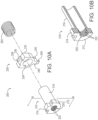
- FIG. 10A shows cutter actuation assembly (200) in greater detail.
- cutter actuation assembly (200) comprises a cocking member (210), an actuation member (230), and a resilient member (202).
- Cocking member (210) comprises a stop portion (212), a slide portion (216), and a bore (220) extending axially though cocking member (210).
- Stop portion (212) is generally configured to act as a mechanical stop for actuation member (230). Accordingly, stop portion (212) forms a shape that is similar to a partially cylindrical flange or another similar feature. As will be described in greater detail below, this mechanical stop feature of stop portion (212) is generally configured to manipulate motion of actuation member (230) as actuation member (230) moves cutter (40) through a predetermined sequence of motion.
- Stop portion (212) further defines an alignment tab (214) extending upwardly relative to bore (220).
- Alignment tab (214) comprises a generally rectangular or cubic shape. In other examples, alignment tab (214) may comprise any other suitable shape such as cylindrical, ball-shaped, triangular, and/or etc.
- alignment tab (214) is configured to be received within a corresponding channel or track disposed within outer housing (14) or an intermediate housing (not shown). Such a channel or track is configured to restrict motion of cocking member (210) to a particular predetermined axial path. Such a channel or track is further configured to prevent rotation of cocking member (210) relative to lead screw (112) to thereby permit lead screw (112) to drive axial motion of cocking member (210), as will be described in greater detail below.
- Slide portion (216) of cocking member (210) extends proximally from stop portion (212).
- Slide portion (216) comprises a generally cylindrical outer surface that is configures to receive actuation member (230).
- actuation member (230) is generally coaxially slidable on slide portion (216) to actuate cutter (40) through a predetermined sequence of motion.
- slide portion (216) has a diameter that is less than the size or diameter of stop portion (212). Accordingly, it should be understood that actuation member (230) is generally coaxially slidable on slide portion (216) until actuation member (230) reaches stop portion (212). At which point, any additional distal sliding relative to slide portion (216) is ceased by stop portion (212).
- bore (220) of cocking member (210) extends through both stop portion (212) and slide portion (216).
- Bore (220) defines a plurality of threads (222) extending inwardly into bore (220).
- threads (222) of bore (220) extend through only the length of bore (220) corresponding to the length of stop portion (212).
- threads (222) of the present example only extend partially though bore (220), it should be understood that in other examples threads (222) can extend for the entire length of bore (220).
- certain complementary features of lead screw (112) may require adjustment in length/size to accommodate the additional length of threads (222).
- Bore (220) is configured to receive at least a portion of lead screw (112).
- bore (220) is configured to receive first threaded portion (116), indented portion (119), and/or slide stop portion (118) of lead screw (112) at various stages during the cutting cycle and the tissue acquisition cycle, as will be described in greater detail below.
- threads (222) are configured to engage threads (117) of first threaded portion (116).
- threads (222) of bore (220) are generally limited to the length of stop portion (212). Because a portion of bore (220) in the present example is un-threaded (e.g., the portion corresponding to slide portion (216)), it should be understood that bore (220) can receive at least a portion of slide stop portion (118) of lead screw (112). However, because slide stop portion (118) defines a diameter approximately equivalent to the major diameter of first threaded portion (116) of lead screw (112), it should be understood that as cocking member (210) moves proximally relative to lead screw (112) such relative motion will only be permitted until threads (222) reach slide stop portion (118) of lead screw (112).
- threads (222) Once threads (222) reach slide stop portion (118) of lead screw (112), an interference between the major diameter of threads (222) and the outer diameter of slide stop portion (118) will prevent further proximal movement of cocking member (210). Moreover, threads (222) at this stage will be adjacent to intended portion (119) and therefore disengaged with threads (117) of first threaded portion (116).
- Actuation member (230) comprises a body (232), an alignment tab (236), and an actuation tab (240).
- Body (232) comprises a shape that is generally similar to stop portion (212) described above with respect to cocking member (210).
- body (232) defines a bore (234) extending through body (232). Bore (234) of body (232) is configured to receive slide portion (216) of cocking member (210).
- actuation member (230) is generally coaxially slidable with slide portion (216) of cocking member (210).
- Alignment tab (236) extends upwardly from body (232). Like with alignment tab (214) of cocking member (210), alignment tab (236) of actuation member (230) is configured to engage a channel or track disposed in outer housing (14) or an intermediate housing (not shown). As similarly discussed above, this configuration generally permits such a channel or tack to restrict the motion of actuation member (230) to a predetermined path. However, unlike alignment tab (214) discussed above, alignment tab (236) of actuation member (230) only extends for a relatively small distance from body (232). Instead of alignment tab (236) extending for the full extent as seen with alignment tab (214), a portion of alignment tab (236) of actuation member (230) is replaced with a release member (238).
- Release member (238) comprises a generally cylindrical shape. As will be described in greater detail below, release member (238) is generally configured to be received by release assembly (400) to temporarily hold actuation member (230) in a cocked position and then selectively release actuation member (230) via actuation of release assembly (400).
- Actuation tab (240) extends downwardly from body (232). Actuation tab (240) comprises an upper portion (242) and a lower portion (244). Upper portion (242) comprises a generally rectangular shape. Although not shown, it should be understood that in some examples upper portion (242) can be configured to be received within a cannel or track of outer housing (14) or an intermediate internal housing (not shown) thereof. In such examples, upper portion (242) functions to restrict motion of actuation member (230) to a predetermined path.
- Lower portion (244) of actuation tab (240) extends downwardly from upper portion (242).
- Lower portion (244) is generally configured to be received within receiving feature (52) of cutter (40).
- actuation member (230) is generally permitted to drive cutter (40) through a predetermined sequence of movements via lower portion (244).
- a channel or track may include an opening or additional channel to prevent lower portion (244) to extend through such a channel or track to receiving feature (52) of cutter (40).
- spring (202) When cutter drive assembly (200) is assembled (e.g., as seen in FIG. 4 ), spring (202) is disposed adjacent to the proximal end of actuation member (230). In addition, spring (202) is disposed coaxially around slide portion (216) of cocking member (210) and/or coaxially around slide stop portion (118) of lead screw (112), depending on the particular stage of operation of drive assembly (100). As will be described in greater detail below, spring (202) is generally configured to drive actuation member (230) distally after actuation member (230) is released by release assembly (400). Spring (202) generally defines an outer diameter that approximately corresponds to the outer diameter of slide portion (216) of cocking member (210). Although spring (202) of the present example is shown as a coil spring, it should be understood that any other suitable resilient member may be used as will be apparent to those of ordinary skill in the art in view of the teachings herein.
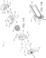
- FIG. 11A shows piercer drive assembly (300) in greater detail.
- piercer drive assembly (300) comprises a cocking member (310), an actuation member (330), a piercer retraction assembly (350), and a spring (302).
- Cocking member (310) of piercer drive assembly (300) is similar to cocking member (210) of cutter drive assembly (200).
- cocking member (310) comprises a stop portion (312), a slide portion (316), and a bore (320) extending axially though cocking member (310).
- Stop portion (312) is generally configured to act as a mechanical stop for actuation member (330).
- stop portion (312) forms a shape that is similar to a partially cylindrical flange or another similar feature.
- this mechanical stop feature of stop portion (312) is generally configured to manipulate motion of actuation member (330) as actuation member (330) moves piercer (22) through a predetermined sequence of motion.
- Stop portion (312) further defines an alignment tab (314) extending upwardly relative to bore (320).
- Alignment tab (314) comprises a generally rectangular or cubic shape. In other examples, alignment tab (314) may comprise any other suitable shape such as cylindrical, ball-shaped, triangular, and/or etc.
- alignment tab (314) is configured to be received within a corresponding channel or track disposed within outer housing (14) or an intermediate housing (not shown). Such a channel or track is configured to restrict motion of cocking member (310) to a particular predetermined axial path.
- Such a channel or track is further configured to prevent rotation of cocking member (310) relative to lead screw (112) and carriage nut (130) to thereby permit lead screw (112) and carriage nut (130) to drive axial motion of cocking member (310), as will be described in greater detail below.
- Slide portion (316) of cocking member (310) extends proximally from stop portion (312).
- Slide portion (316) comprises a generally cylindrical outer surface that is configures to receive actuation member (330).
- actuation member (330) is generally coaxially slidable on slide portion (316) to actuate cutter (40) through a predetermined sequence of motion.
- slide portion (316) has a diameter that is less than the size or diameter of stop portion (312). Accordingly, it should be understood that actuation member (330) is generally coaxially slidable on slide portion (316) until actuation member (330) reaches stop portion (312). At which point, any additional distal sliding relative to slide portion (316) is ceased by stop portion (312).
- bore (320) of cocking member (310) extends through both stop portion (312) and slide portion (316).
- Bore (320) defines a plurality of threads (322) extending inwardly into bore (320).
- threads (322) of bore (320) extend through only the longitudinal length of bore (320) corresponding to the length of stop portion (312).
- threads (322) can alternatively extend for the entire length of bore (320).
- certain complementary features of carriage nut (130) may require adjustment in length/size to accommodate the additional length of threads (322).
- Bore (320) is configured to receive at least a portion of carriage nut (130).
- bore (320) is configured to receive threaded portion (136), indented portion (144), and/or slide portion (140) of carriage nut (130) at various stages during the cutting cycle and the tissue acquisition cycle, as will be described in greater detail below.
- threads (322) are configured to engage threads (138) of threaded portion (136) of carriage nut (130).
- threads (322) of bore (320) are generally limited to the length of stop portion (312). Because a portion of bore (320) in the present example is un-threaded (e.g., the portion corresponding to slide portion (316)), it should be understood that bore (320) can receive at least a portion of slide portion (140) of carriage nut (130). However, because slide portion (140) defines a diameter approximately equivalent to the major diameter of threaded portion (136) of carriage nut (130), it should be understood that as cocking member (310) moves proximally relative to carriage nut (130) and lead screw (112) such relative motion will only be permitted until threads (322) reach slide portion (140) of carriage nut (130).
- threads (322) Once threads (322) reach slide portion (140) of carriage nut (130), an interference between the major diameter of threads (322) and the outer diameter of slide portion (140) will prevent further proximal movement of cocking member (310). Moreover, threads (322) at this stage will be adjacent to intended portion (144) and therefore disengaged with threads (138) of threaded portion (136).
- Actuation member (330) comprises a body (332), an alignment tab (336), and an actuation tab (340).
- Body (332) comprises a shape that is generally similar to stop portion (312) described above with respect to cocking member (310).
- body (332) defines a bore (334) extending through body (332). Bore (334) of body (332) is configured to receive slide portion (316) of cocking member (310).
- actuation member (330) is generally coaxially slidable with slide portion (316) of cocking member (310).
- Alignment tab (336) extends upwardly from body (332). Like with alignment tab (314) of cocking member (310), alignment tab (336) of actuation member (330) is configured to engage a channel or track disposed in outer housing (14) or an intermediate housing (not shown). As similarly discussed above, this configuration generally permits such a channel or tack to restrict the motion of actuation member (330) to a predetermined path. However, unlike alignment tab (314) discussed above, alignment tab (336) of actuation member (330) only extends for a relatively small distance from body (332). Instead of alignment tab (336) extending for the full extent as seen with alignment tab (314), a portion of alignment tab (336) of actuation member (330) is replaced with a release member (338).
- Release member (338) comprises a generally cylindrical shape. As will be described in greater detail below, release member (338) is generally configured to be received by release assembly (400) to temporarily hold actuation member (330) in a cocked position and then selectively release actuation member (330) via actuation of release assembly (400).
- Actuation tab (340) extends downwardly from body (332).
- Actuation tab (340) comprises an upper portion (342) and a lower portion (344).
- Upper portion (342) comprises a generally rectangular shape.
- upper portion (342) can be configured to be received within a cannel or track of outer housing (14) or an intermediate internal housing (not shown) thereof.
- upper portion (342) functions to restrict motion of actuation member (330) to a predetermined path.
- Lower portion (344) of actuation tab (340) extends downwardly from upper portion (342).
- Lower portion (344) is generally configured to be received within receiving feature (32) of piercer (22).
- actuation member (330) is generally permitted to drive piercer (22) through a predetermined sequence of movements via lower portion (344).
- a channel or track may include an opening or additional channel to prevent lower portion (344) to extend through such a channel or track to receiving feature (32) of piercer (22).
- Piercer retraction assembly (350) is disposed proximally of cocking member (310) and actuation member (330). As will be described in greater detail below, piercer retraction assembly (350) is generally configured to axially translate piercer drive assembly (300) relative to lead screw (112). Piercer retraction assembly (350) comprises a first retraction member (352) and a second retraction member (370), and a retainer (390) disposed between first retraction member (352) and second retraction member (370).
- First retraction member (352) comprises a body (354) and a support arm (360).
- Body (354) defines a bore (356) extending entirely through body (354).
- Body (354) further includes a counter-bore (358) disposed adjacent to bore (356).
- Counter-bore (358) extends distally only partially though body (354) from the proximal end thereof.
- bore (356) and counter-bore (358) are generally sized to receive slide portion (316) of cocking member (310) and slide portion (140) of carriage nut (130).
- Bore (356) defines a diameter that is generally undersized relative to a diameter defined by retainer (390), while counter-bore (358) defines a diameter that is generally oversized relative to the diameter defined by retainer (390). As will be described in greater detail below, this difference in diameter between bore (356) and counter-bore (358) is configured to secure retainer (390) between first retraction member (352) and second retraction member (370).
- Support arm (360) of first retraction member (352) extends distally from body (354).
- the distal extension of support arm (360) defines a length that is generally equivalent to spring (302) in a compressed state.
- support arm (360) defines a receiving indentation (362).
- Receiving indentation (362) is generally configured to receive at least a portion of release member (338) of actuation member (330).
- receiving indentation (362) is generally configured to operate in conjunction with at least a portion of release assembly (400) to selectively hold release member (338) in a predetermined position relative to first retraction member (352).
- Second retraction member (370) comprises a body (372) having a generally rectangular shape.
- Body (372) defines a bore (374) and a counter-bore (376) disposed coaxially with bore (374).
- Bore (374) extends entirely though body (372), while counter-bore (376) extends distally through only a portion of body (372) from the distal end thereof.
- Bore (374) and counter-bore (376) are both configured to receive at least a portion of lead screw (112) such that lead screw (112) can extend entirely though second retraction member (370).
- a diameter defined by counter-bore (376) is larger than a diameter defined by bore (374) to accommodate retainer (390) within counter-bore (376).
- this differential in the diameters of bore (374) and counter-bore (376) is configured to prevent proximal movement of retainer (390) relative to second retraction member (370) such that retainer (390) is generally held between first retraction member (352) and second retraction member (370).
- Bore (374) further includes a protrusion (378) extending downwardly into the space defined by bore (374).
- Protrusion (378) comprises a generally cylindrical shape, although any other suitable shape may be used.
- protrusion (378) is configured to engage threads (125) of lead screw (112) to drive translation of second retraction member (370) in response to rotation of lead screw (112).
- retainer (390) is disposed between first retraction member (352) and second retraction member (370).
- Retainer (390) generally comprises a circular shape similar to a washer or other similar structure.
- Retainer (390) includes a bore (392) extending entirely though retainer (390). Bore (392) of retainer (390) is sized to permit retainer (390) to fit within annular channel (142) of carriage nut (130). Because retainer (390) is secured between first retraction member (352) and second retraction member (370), it should be understood that when retainer (390) generally axially secures movement of carriage nut (130) relative to piercer retraction assembly (350) via engagement between retainer (390) and annular channel (142).
- axial movement of carriage nut (130) will generally result in axial movement of piercer retraction assembly (350).
- this relationship between movement of carriage nut (130) and piercer retraction assembly (350) generally results in retraction of piercer (22) during the tissue acquisition cycle.
- retainer (390) axially secures movement of carriage nut (130) relative to piercer retraction assembly (350), it should be understood that carriage nut (130) is rotatably movable relative to piercer retraction assembly (350). In other words, retainer (390) only secures axial movement of carriage nut (130), not rotational movement.
- retainer (390) can be adjacent to one or more bearings to disposed within either or both counter-bores (358, 376) of first retraction member (352) and second retraction member (370), respectively. In such examples, bearings can be used to promote the rotatability of carriage nut (130) relative to piercer retraction assembly (350).
- retainer (390) is shown as having a generally circular shape, it should be understood that in some examples retainer (390) may comprise a variety of other shapes. For instance, in other examples retainer (390) comprises a c-washer, a snap-on washer, a circlip, a Jesus clip, and/or any other suitable retaining feature as will be apparent to those of ordinary skill in the art in view of the teachings herein.
- spring (302) is disposed between the proximal end of actuation member (330) and the distal end of body (354) of first retraction member (352).
- spring (302) is disposed coaxially around slide portion (316) of cocking member (310) and/or coaxially around slide portion (140) of carriage nut (130), depending on the particular stage of operation of drive assembly (100).
- spring (302) is generally configured to drive actuation member (330) distally after actuation member (330) is released by release assembly (400).
- Spring (302) generally defines an outer diameter that approximately corresponds to the outer diameter of slide portion (316) of cocking member (310). Although spring (302) of the present example is shown as a coil spring, it should be understood that any other suitable resilient member may be used as will be apparent to those of ordinary skill in the art in view of the teachings herein.
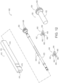
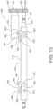
- FIGS. 12 and 13 show release assembly (400) in greater detail.
- release assembly (400) comprises a nut member (410), a secondary lead screw (420), a motor assembly (430), a first latch member (440), and a second latch member (450).
- Nut member (410) comprises a body (412) with an elongate bore (414) extending longitudinally therethrough.
- bore (414) includes a threaded portion (not shown) including threads (not shown) extending into bore (414).
- threaded portion of bore (414) is configured to engage at least a portion of secondary lead screw (420) to permit secondary lead screw (420) to drive proximal and distal translation of nut member (410).
- Nut member (410) further includes a first latch actuator (416) and a second latch actuator (418) extending downwardly from body (412). Both first latch actuator (416) and second latch actuator (418) comprise a generally cylindrical shape, although any other suitable shape may be used.
- First latch actuator (416) is associated with first latch member (440), while second latch actuator (418) is associated with second latch member (450).
- latch actuators (416, 418) are generally configured to engage with a corresponding latch member (440, 450) to release cutter drive assembly (200) and piercer drive assembly (300) to fire cutter (40) and piercer (22), respectively.
- Secondary lead screw (420) comprises a drive rod (422) and a drive member (426).
- Drive rod (422) defines a generally cylindrical shape with a plurality of threads (424) extending along at least a portion of the length of drive rod (422). Threads (424) are configured to engage corresponding threads disposed within nut member (410). This engagement between threads (424) of drive rod (422) and the threads of nut member (410) generally results in the conversion of rotation motion of secondary lead screw (420) into translation of nut member (410). As will be described in greater detail below, this motion of nut member (410) via lead screw (420) is generally configured to selectively initiate firing of cutter (40) and piercer (22).
- Drive member (426) of secondary lead screw (420) is fixedly secured to the proximal end of drive rod (422).
- Drive member (426) is configured to impart rotary motion onto drive rod (422) from motor assembly (430).
- drive member (426) comprises a plurality of teeth (428).
- teeth (428) are configured to engage at least a portion of motor assembly (430) such that rotatory motion provided by motor assembly (430) is communicated to drive rod (422) via teeth (428) of drive member (426).
- Motor assembly (430) assembly comprises a rotary power source (432) and a drive member (434) in rotary communication with rotary power source (432).
- Rotary power source (432) in the present example is configured as an electrical motor.
- rotary power source (432) can be configured as a variety of other rotary power sources such as pneumatic motors, piezoelectric motors, and/or etc.
- Drive member (434) of motor assembly (430) is configured to communicate rotary power from rotary power source (432) to secondary lead screw (420).
- drive member (434) comprises a plurality of teeth (436) that are configured to engage with teeth (428) of drive member (426) described above with respect to secondary lead screw (420). Though engagement between teeth (428, 436), drive members (426, 434) are rotated, thereby communicating rotary power from motor (432) to drive member (426) of secondary lead screw (420).
- drive members (426, 434) are described herein as being essentially gears with teeth (428, 436), it should be understood that in other examples any other suitable rotary transmission may be used.
- suitable rotary transmissions may include a belt drive, a drive with additional gears to provide a gear ratio between motor (432) and drive rod (422), and/or etc.
- First latch member (440) comprises lever portion (442), a pivot portion (444), and a catch portion (446).
- Lever portion (442), pivot portion (444), and catch portion (446) are all integrally connected to form L-shaped structure.
- Lever portion (442) and catch portion (446) each define one leg of the L-shape, pivot portion (444) is disposed between lever portion (442) and catch portion (448).
- Pivot portion (444) includes an opening (445) extending entirely through latch member (440) such that a pin or other similar structure may be received by opening (445) for pivoting of first latch member (440) about an axis defined by opening (445).
- this pivoting action generally permits first latch member (440) to selectively catch and release release member (238) of cutter drive assembly (200).
- Catch portion (446) defines a ramp feature (448) and a recessed feature (449).
- Ramp feature (448) is generally triangular in shape, while adjacent recessed feature (449) is generally semicircular. Both ramp feature (448) and recessed feature (449) are configured to engage release member (238) of cutter drive assembly (200).
- ramp feature (448) functions to pivot first latch member (440) away from release member (238) to a receiving or releasing position so that release member (238) can enter recessed feature (449).
- recessed feature (449) catches or otherwise selectively secures release member (238) when first latch member (440) is pivoted to a cocked position.
- first latch member (440) may include a resilient feature to resiliently bias first latch member (440) toward the cocked position once release member (238) is received by recessed feature (449).
- Second latch member (450) comprises lever portion (452), a pivot portion (454), and a catch portion (456).
- Lever portion (452), pivot portion (454), and catch portion (456) are all integrally connected to form an L-shaped structure.
- Lever portion (452) and catch portion (456) each define one leg of the L-shape, pivot portion (454) is disposed between lever portion (452) and catch portion (458).
- Pivot portion (454) includes an opening (455) extending entirely through latch member (450) such that a pin or other similar structure may be received by opening (455) for pivoting of second latch member (450) about an axis defined by opening (455).
- this pivoting action generally permits second latch member (450) to selectively catch and release release member (338) of piercer drive assembly (300).
- Catch portion (456) defines a ramp feature (458) and a recessed feature (459).
- Ramp feature (458) is generally triangular in shape, while adjacent recessed feature (459) is generally semicircular. Both ramp feature (458) and recessed feature (459) are configured to engage release member (338) of piercer drive assembly (300).
- ramp feature (458) functions to pivot second latch member (450) away from release member (338) to a receiving or releasing position so that release member (338) can enter recessed feature (459).
- recessed feature (459) catches or otherwise selectively secures release member (338) when second latch member (450) is pivoted to a cocked position.
- first latch member (450) may include a resilient feature to resiliently bias first latch member (450) toward the cocked position once release member (338) is received by recessed feature (459).
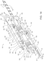
- FIGS. 14-26 show an exemplary use of biopsy device (10) described above.
- drive assembly (100) is generally used to cock and then fire piercer (22) and cutter (40) in a predetermined sequence to penetrate a suspicious lesion and then sever a tissue sample thereof.
- piercer (22) and cutter (40) are fired, piercer (22) is retracted relative to cutter (40) to permit collection of the severed tissue by an operator.
- the cocking and firing process may then be repeated as many times as desired to collect as many tissue samples as desired by the user.
- FIGS. 14-16 show an exemplary cocking sequence that results in piercer (22) and cutter (40) being prepared for firing.
- drive assembly (100) can begin in an initial position as shown in FIG. 15 .
- drive assembly (100) may begin in a cocked position as shown in FIG. 15 .
- piercer (22) and cutter (40) are each in a distal position.
- cutter drive assembly (200) and piercer drive assembly (300) are also in a distal uncocked position.
- Release assembly (400) is disengaged from both cutter drive assembly (200) and piercer drive assembly (300) when cutter drive assembly (200) and piercer drive assembly (300) are in the distal position.
- cocking member (210) When cutter drive assembly (200) is in the distal position, cocking member (210) is positioned on the distal end of first threaded portion (116) of lead screw (112). Actuation member (230) is positioned adjacent to stop portion (212) of cocking member (210) via spring (202). In particular, because release member (238) of actuation member (230) is disengaged from release assembly (400), release member (238) is freely movable along the axis of lead screw (112). Despite actuation member (230) being freely movable along the axis of lead screw (112), spring (202) is resiliently biased to urge actuation member (230) distally into the position shown in FIG. 14 . Thus, actuation member (230) is urged adjacent to cocking member (210) by spring (202).
- cocking member (310) When piercer drive assembly (300) is in the distal position, cocking member (310) is positioned on the distal end of threaded portion (136) of carriage nut (130). Carriage nut (130) is correspondingly positioned on the distal end of second threaded portion (124) of lead screw (112) such that cocking member (310) is in the distal most position relative to both carriage nut (130) and lead screw (112).
- Actuation member (330) is positioned adjacent to stop portion (312) of cocking member (310) via spring (302). In particular, because release member (338) of actuation member (330) is disengaged from release assembly (400), release member (338) is freely movable along the axis of lead screw (112) and carriage nut (130).
- actuation member (330) being freely movable along the axis of lead screw (112) and carriage nut (130), spring (302) is resiliently biased to urge actuation member (330) distally into the position shown in FIG. 14 .
- actuation member (330) is urged adjacent to cocking member (310) by spring (302).
- piercer retraction assembly (350) of piercer drive assembly (300) is also in a distal position.
- piercer retraction assembly (350) is generally separate from cocking member (310) and actuation member (330).
- piercer retraction assembly (350) is axially fixed relative to carriage nut (130) by engagement between retainer of retraction assembly (350) and annular channel (142) of carriage nut (130). Because of this, piercer retraction assembly (350) is axially fixed near the distal end of carriage nut (130) with axial movement of piercer retraction assembly (350) only resulting from axial movement of carriage nut (130).
- actuation member (16) On the exterior of outer housing (14). Actuation of actuation member (16) then provides a signal to rotary power source (164) of needle cocking assembly (110). Upon receiving such a signal, rotary power source (164) begins rotating lead screw (112) via rotary communication features (152, 162) in a first direction as shown in FIG. 15 .
- Rotation of lead screw (112) in the first direction generally causes cutter drive assembly (200) and piercer drive assembly (300) to translate proximally.
- rotation of lead screw (112) causes threads (117) of first threaded portion (118) to engage threads (222) of cocking member (210).
- This engagement between threads (117, 222) causes cocking member (210) to translate proximally.
- stop portion (212) of cocking member (210) engages actuation member (230) to correspondingly push actuation member (230) proximally.
- Actuation member (230) in turn acts on spring (202) to thereby compress spring (202).
- Proximal translation of cocking member (210) and actuation member (230) continues until release member (238) contacts first latch member (440) of release assembly (410). Once such contact is made, release member (238) of actuation member (230) engages ramp feature (448) of first latch member (440) to pivot first latch member (440) outwardly (e.g., into the page of FIG. 15 ) as actuation member (230) is driven proximally. Proximal translation of actuation member (230) and pivoting of first latch member (440) will continue until release member (238) is adjacent to recessed feature (449) of first latch member (440).
- first latch member (440) will have pivoted inwardly (e.g., out of the page of FIG. 15 ) to capture release member (238) of actuation member (230) within recessed feature (449) of first latch member (440).
- release member (238) is captured within recessed feature (449)
- actuation member (230) will be generally held in the axial position shown in FIG. 15 via first latch member (440).
- Rotation of lead screw (112) also rotates carriage nut (130) via key (134) of carriage nut (130) and keyway (122) of lead screw (112).
- piercer drive assembly (300) is generally translated proximally.
- threads (138) of carriage nut (130) engage threads (322) disposed within bore (320) of cocking member (310).
- the engagement between threads (138, 322) causes cocking member (310) to translate proximally.
- stop portion (312) of cocking member (310) engages actuation member (330) to correspondingly push actuation member (330) proximally.
- Actuation member (330) in turn acts on spring (302) to thereby compress spring (302).
- Proximal translation of cocking member (310) and actuation member (330) continues until release member (338) contacts second latch member (450) of release assembly (410). Once such contact is made, release member (338) of actuation member (330) engages ramp feature (458) of second latch member (450) to pivot second latch member (450) outwardly (e.g., into the page of FIG. 15 ) as actuation member (330) is driven proximally. Proximal translation of actuation member (330) and pivoting of second latch member (450) will continue until release member (338) is adjacent to recessed feature (459) of second latch member (450).
- release member (338) of actuation member (330) is adjacent to recessed feature (459) of second latch member (450)
- rotation of carriage nut (130) via lead screw (112) and corresponding proximal translation of actuation member (330) via cocking member (310) will stop.
- second latch member (450) will have pivoted inwardly (e.g., out of the page of FIG. 15 ) to capture release member (338) of actuation member (330) within recessed feature (459) of second latch member (450).
- release member (338) is captured within recessed feature (459)
- actuation member (330) will be generally held in the axial position shown in FIG. 15 via second latch member (450).
- drive assembly (100) is in a cocked position.
- drive assembly (100) is shown and described herein as initially transitioning to the cocked position from the initial position, it should be understood that in some examples the procedure may begin with drive assembly (100) being in the cocked position. Regardless, in the cocked position, springs (202, 302) are compressed for firing. However, because each cocking member (210, 310) is adjacent to each actuation member (230, 330), cutter (40) and piercer (22) cannot be fired. Thus, it should be understood that when drive assembly (100) is in the cocked position, cutter (40) and piercer (22) are merely in position for firing, but drive assembly (100) is not yet fully armed.
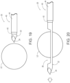
- an operator may inert needle assembly (20) into tissue of a patient. As shown in FIG. 19 , insertion may be performed to position needle assembly (20) adjacent to a suspicious lesion (LE). In some uses, inserting needle assembly (20) into tissue of a patient may be desirable to prevent inadvertent firing of piercer (22) or cutter (40). Of course, it should be understood that an operator may position needle assembly (20) when drive assembly (100) is in other positions, as will be described in greater detail below.
- an operator may transition drive assembly (100) from the cocked position shown in FIG. 15 to a ready position shown in FIG. 16 .
- an operator may push actuation member (16) a second time. Pressing actuation member (16) once again sends a signal to rotary power source (164) of needle cocking assembly (110) to initiate rotation of lead screw (112) in a second direction, opposite of the first direction.
- Rotation of lead screw (112) in the opposite direction generally causes cocking member (210) of cutter drive assembly (200) and cocking member (310) of piercer drive assembly (300) to each translate distally relative to lead screw (112).
- threads (117) of first threaded portion (116) again engage threads (222) of cocking member (210).
- this engagement causes cocking member (210) to translate distally.
- actuation member (230) and spring (202) are not fixedly secured to cocking member (210), actuation member (230) and spring (202) remain held in position by first latch member (440) of release assembly (400). Translation of cocking member (210) continues until cocking member (210) reaches the distal end of first threaded portion (116) of lead screw (112) as shown in FIG. 16 .
- drive assembly (100) is in the ready position. Once drive assembly (100) is in the ready position, an operator may position needle assembly (20) into tissue of a patient adjacent to suspicious lesion (LE) as shown in FIG. 19 , if operator had not already done so prior to transitioning drive assembly (100) from the cocking position to the ready position.
- L suspicious lesion
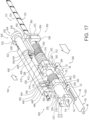
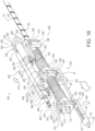
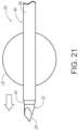
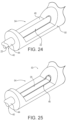
- FIGS. 17-18 , and 19-21 show the firing sequence in greater detail.
- an operator may press actuation member (16) on outer housing (14) a third time.
- actuation member (16) is pressed, a signal now sent to motor (432) of release assembly (400). This signal causes motor (432) to supply rotary power to secondary lead screw (420) via drive members (426, 434) to thereby rotate secondary lead screw (420).
- threads (424) of secondary lead screw (420) engage the threads disposed within body (412) of nut member (410).
- second latch actuator (418) engages lever portion (452) of second latch member (450) to begin to pivot second latch member (450) away from release member (338) of piercer drive assembly (300). Further proximal translation of nut member (410) eventually results in second latch member (450) fully pivoting to disengage release member (338) from recessed feature (459) of second latch member (450) as shown in FIG.17 .
- actuation member (330) is free to translate axially relative to lead screw (112). Because spring (302) was previously compressed during cocking, spring (302) will now rapidly urge actuation member (330) distally. As described above, actuation member (330) includes actuation tab (340), which is secured to receiving feature (32) of piercer (22). Thus, it should be understood that rapid translation of actuation member (330) will result in corresponding rapid translation of piercer (22). Rapid translation of piercer (22) will result in distal tip (24) and notch (26) of piercer (22) penetrating through suspicious lesion (LE) as shown in FIG. 20 .
- motor (432) of release assembly (400) will stop, thereby stopping further proximal movement of nut member (410) via secondary lead screw (420).
- proximal translation of nut member (410) will stop prior to first latch actuator (416) reaching first latch member (440) for firing of cutter (40).
- motor (432) may continue rotating without stopping after firing of piercer (22). In these uses, piercer (22) is fired first, followed by a relatively short delay, and then cutter (40) is fired using the sequence described below.
- an operator may reinitiate rotation of motor (432) and corresponding proximal translation of nut member (410) by pressing actuation member (16) on outer housing (14) a fourth time.
- This causes motor (432) of release assembly (400) to continue rotation of secondary lead screw (420).
- engagement between threads (424) of secondary lead screw (420) and the threads of nut member (410) during rotation of secondary lead screw (420) causes nut member (410) to retract proximally.
- first latch actuator (416) will engage lever portion (442) of first latch member (440).
- first latch actuator (416) pushing lever portion (442) to pivot first latch member (440) away from release member (238) of actuation member (230) as shown in FIG. 18 .
- This pivoting of first latch member (440) will eventually result in disengagement of release member (238) of actuation member (230) from first latch member (440).
- actuation member (230) With release member (238) of actuation member (230) disengaged from first latch member (440), actuation member (230) is free to translate axially relative to lead screw (112). Because spring (202) was previously compressed during cocking, spring (202) will now rapidly urge actuation member (230) distally. As described above, actuation member (230) includes actuation tab (240), which is secured to receiving feature (52) of cutter (40). Thus, it should be understood that rapid translation of actuation member (230) will result in corresponding rapid translation of cutter (40). Rapid translation of cutter (40) will result in distal end (42) of cutter (40) penetrating through suspicious lesion (LE) as shown in FIG. 21 to sever a tissue sample into notch (26) of piercer (22).
- FIGS. 22-25 show an exemplary sequence for retracting piercer (22) relative to cutter (40) to collect a tissue sample after the tissue sample has been acquired using the firing sequence described above.
- the piercer (22) retraction sequence generally involves retracting piercer (22) relative to cutter (40) to expose notch (26) of piercer within the tissue collection feature (54) of cutter (40).
- notch (26) When piercer (22) is retracted in this way, an operator may extract a tissue sample from notch (26) for further analysis and processing.
- the piercer (22) retraction sequence begins by returning drive assembly (100) to the cocked position described above with respect to FIG. 15 .
- drive assembly (100) is in the cocked position shown in FIGS. 4 and 15
- piercer (22) is correspondingly disposed in a distal position.
- tissue collection feature (54) of cutter (40) is generally blocked by piercer (22).
- an operator may press actuation member (16) on outer housing (14) a fifth time.
- drive assembly (100) is generally transitioned to the cocked position by rotating lead screw (112) in the first direction to translate cocking members (210, 310) of cutter drive assembly (200) and piercer drive assembly (300) proximally relative to lead screw (112).
- piercer retraction assembly (350) will begin to engage second threaded portion (124) of lead screw (112).
- protrusion (378) of second retraction member (370) is received by threads (125) of second threaded portion (124).
- engagement between protrusion (378) and threads (125) pulls second retraction member (370) proximally as shown in FIG. 22 .
- second retraction member (370) is secured to first retraction member (352), proximal movement of second retraction member (370) also pulls first retraction member (352) proximally.
- retainer (390) is positioned between first retraction member (352) and second retraction member (370) to axially secure carriage nut (130) to piercer retraction assembly (350), proximal movement of first retraction member (352) and second retraction member (370) will result in corresponding proximal movement of carriage nut (130).
- piercer drive assembly (300) disposed on carriage nut (130)
- translation of carriage nut (130) also results in translation of piercer drive assembly (300).
- Proximal translation of piercer retraction assembly (350), piercer drive assembly (300), and piercer (22) continues until piercer retraction assembly (350) reaches the distal position shown in FIG. 23 .
- piercer retraction assembly (350) reaches the distal position, rotation of lead screw (112) stops, thereby stopping further proximal translation of piercer retraction assembly (350).
- piercer (22) When piercer drive assembly (300) is in the distal position, piercer (22) is also in a distal position as shown in FIG. 25 . As can be seen in FIG. 25 , when piercer (22) is in the distal position, notch (26) of piercer (22) is aligned with tissue collection feature (54) of cutter (40). This alignment provides access to notch (26) through cut out (46) in cutter (40). At this stage, an operator may collect a tissue sample from notch (26) for further examination, analysis, investigation, and/or etc.
- an operator may complete the biopsy procedure by removing biopsy device (10) from the patient.
- an operator may desire to collect additional samples using a single insertion of needle assembly (20) into a patient.
- an operator may press actuation member (16) on outer housing (14) a sixth time. This will cause rotation communication feature (162) of needle cocking assembly to reactivate and return drive assembly (100) to the initial position or the cocking position via rotation of lead screw (112).
- An operator may then follow the same procedure described above one or more times until a desired number of tissue samples are collected.
Landscapes
- Health & Medical Sciences (AREA)
- Life Sciences & Earth Sciences (AREA)
- Medical Informatics (AREA)
- Engineering & Computer Science (AREA)
- Biomedical Technology (AREA)
- Heart & Thoracic Surgery (AREA)
- Pathology (AREA)
- Molecular Biology (AREA)
- Surgery (AREA)
- Animal Behavior & Ethology (AREA)
- General Health & Medical Sciences (AREA)
- Public Health (AREA)
- Veterinary Medicine (AREA)
- Surgical Instruments (AREA)
- Infusion, Injection, And Reservoir Apparatuses (AREA)
Claims (17)
- Kernnadelbiopsiegerät (10), umfassend:(a) eine Nadelanordnung (20), wobei die Nadelanordnung (20) einen Dorn (22) und einen Hohlschneider (40) einschließt, wobei der Dorn (22) eine scharfe distale Spitze und eine Kerbe (26) proximal zur distalen Spitze einschließt, wobei der Dorn (22) verschiebbar innerhalb des Schneiders (40) angeordnet ist, um eine Gewebeprobe in die Kerbe des Dorns einzuschneiden;(b) eine Schneidantriebsanordnung (200), wobei die Schneidantriebsanordnung so konfiguriert ist, dass sie den Schneider (40) selektiv abfeuert;(c) eine Dornantriebsanordnung (300), wobei die Dornantriebsanordnung so konfiguriert ist, dass sie den Dorn (22) selektiv abfeuert; und(d) eine Antriebsanordnung (100), die eine Dornrückzugsanordnung (350) aufweist,dadurch gekennzeichnet, dass die Antriebsanordnung eine Leitspindel (112) einschließt, die mit der Dornantriebsanordnung (300) und der Schneidantriebsanordnung (200) in Eingriff steht, so dass eine Drehung der Leitspindel (112) nacheinander einen Abschnitt der Dornantriebsanordnung (300) und der Schneidantriebsanordnung (200) verschiebt,wobei eine Drehung der Leitspindel (112) den Dorn (22) durch Zurückziehen der Dornrückzugsanordnung (350) unabhängig von dem Schneider (40) zurückzieht, während die Nadelanordnung (20) innerhalb eines Patienten angeordnet ist, um einen distalen Abschnitt des Dorns (22) einem Äußeren eines Patienten auszusetzen, während zumindest ein Abschnitt des Dorns in dem Schneider (40) verbleibt.
- Kernnadelbiopsiegerät (10) nach Anspruch 1, weiter umfassend eine Nadelspannanordnung (110), die die Leitspindel (112) umfasst, wobei die Nadelspannanordnung so konfiguriert ist, dass sie zumindest einen Abschnitt der Schneidantriebsanordnung (200), der Dornantriebsanordnung (300) und der Dornrückzugsanordnung (350) bewegt.
- Kernnadelbiopsiegerät (10) nach Anspruch 2, wobei die Leitspindel (112) einen ersten Gewindeabschnitt (116) und einen zweiten Gewindeabschnitt (124) einschließt, wobei der erste Gewindeabschnitt Gewinde einschließt, die eine erste Steigung aufweisen, wobei der zweite Gewindeabschnitt Gewinde einschließt, die eine zweite Steigung aufweisen, wobei die erste Steigung relativ zur zweiten Steigung unterschiedlich ist.
- Kernnadelbiopsiegerät (10) nach Anspruch 3, wobei der erste Gewindeabschnitt (116) so konfiguriert ist, dass er in die Schneidantriebsanordnung (200) eingreift, wobei der zweite Gewindeabschnitt (124) so konfiguriert ist, dass er in die Dornrückzugsanordnung (350) eingreift.
- Kernnadelbiopsiegerät (10) nach Anspruch 4, wobei die Nadelspannanordnung (110) weiter eine Schlittenmutter (130) einschließt, die auf der Leitspindel (112) angeordnet ist, wobei die Schlittenmutter einen Gewindeabschnitt (136) einschließt.
- Kernnadelbiopsiegerät (10) nach Anspruch 5, wobei der Gewindeabschnitt (136) der Schlittenmutter (130) so konfiguriert ist, dass er in die Dornantriebsanordnung (300) eingreift.
- Kernnadelbiopsiegerät (10) nach Anspruch 6, wobei die Schlittenmutter (133) mit der Dornrückzugsanordnung (350) axial beweglich ist.
- Kernnadelbiopsiegerät (10) nach Anspruch 6, wobei die Dornantriebsanordnung (300) als Reaktion auf eine axiale Bewegung der Schlittenmutter (130) axial beweglich ist.
- Kernnadelbiopsiegerät (10) nach Anspruch 6, wobei die Dornantriebsanordnung (300) als Reaktion auf eine Drehbewegung der Schlittenmutter (130) axial beweglich ist.
- Kernnadelbiopsiegerät (10) nach Anspruch 1, weiter umfassend eine Freigabeanordnung (400), wobei die Freigabeanordnung mit zumindest einem Abschnitt der Schneidantriebsanordnung (200) und der Dornantriebsanordnung (300) in Verbindung steht, um selektiv ein Abfeuern des Schneiders (40) und des Dorns (22) einzuleiten.
- Kernnadelbiopsiegerät (10) nach Anspruch 10, wobei die Freigabeanordnung (400) eine sekundäre Leitspindel (420) und ein Mutternelement (410) einschließt, wobei das Mutternelement auf eine Drehung der sekundären Leitspindel reagiert, um ein Abfeuern des Schneiders und des Dorns in einer vorbestimmten Reihenfolge einzuleiten.
- Kernnadelbiopsiegerät (10) nach Anspruch 1, wobei zumindest ein Abschnitt der Schneidantriebsanordnung (200) und der Dornantriebsanordnung (300) durch eine Feder angetrieben wird.
- Kernnadelbiopsiegerät (10) nach Anspruch 1, wobei zumindest ein Abschnitt der Schneidantriebsanordnung (200) und der Dornantriebsanordnung (300) durch einen Motor angetrieben wird.
- Kernnadelbiopsiegerät (10) nach Anspruch 13, wobei der Motor ein Elektromotor ist.
- Kernnadelbiopsiegerät (10) nach Anspruch 1, wobei die Dornrückzugsanordnung (350) so konfiguriert ist, dass sie beim Zurückziehen des Dorns (22) zumindest einen Abschnitt der Dornantriebsanordnung (300) zurückzieht.
- Kernnadelbiopsiegerät (10) nach Anspruch 1, wobei die Schneidantriebsanordnung (200) distal von der Dornantriebsanordnung (300) beabstandet ist, so dass die Schneidantriebsanordnung und die Dornantriebsanordnung getrennt sind.
- Kernnadelbiopsiegerät (10) nach Anspruch 1, weiter umfassend eine Nadelspannanordnung (110), die so konfiguriert ist, dass sie mit der Schneidantriebsanordnung (200) und der Dornantriebsanordnung (300) in Eingriff tritt, um die Schneidantriebsanordnung und die Dornantriebsanordnung zu spannen, und eine Freigabeanordnung (400), die so konfiguriert ist, dass sie mit der Schneidantriebsanordnung und der Dornantriebsanordnung in Eingriff tritt, um die Schneidantriebsanordnung und die Dornantriebsanordnung selektiv freizugeben und abzufeuern, um dadurch den Schneider (40) und den Dorn (22) selektiv freizugeben und abzufeuern.
Applications Claiming Priority (2)
| Application Number | Priority Date | Filing Date | Title |
|---|---|---|---|
| US201662407201P | 2016-10-12 | 2016-10-12 | |
| PCT/US2017/056123 WO2018071530A1 (en) | 2016-10-12 | 2017-10-11 | Core needle biopsy device for collecting multiple samples in a single insertion |
Publications (2)
| Publication Number | Publication Date |
|---|---|
| EP3525680A1 EP3525680A1 (de) | 2019-08-21 |
| EP3525680B1 true EP3525680B1 (de) | 2025-02-19 |
Family
ID=60186391
Family Applications (1)
| Application Number | Title | Priority Date | Filing Date |
|---|---|---|---|
| EP17791244.1A Active EP3525680B1 (de) | 2016-10-12 | 2017-10-11 | Kernnadelbiopsiegerät zum sammeln einer vielzahl von proben mit einem einzigen stich |
Country Status (11)
| Country | Link |
|---|---|
| US (2) | US11602335B2 (de) |
| EP (1) | EP3525680B1 (de) |
| JP (1) | JP7100025B2 (de) |
| KR (2) | KR102594842B1 (de) |
| CN (1) | CN109982650A (de) |
| AU (1) | AU2017343642A1 (de) |
| BR (1) | BR112019007374A2 (de) |
| CA (1) | CA3040275A1 (de) |
| ES (1) | ES3014938T3 (de) |
| PL (1) | PL3525680T3 (de) |
| WO (1) | WO2018071530A1 (de) |
Families Citing this family (9)
| Publication number | Priority date | Publication date | Assignee | Title |
|---|---|---|---|---|
| US20220249075A1 (en) * | 2016-10-12 | 2022-08-11 | Devicor Medical Products, Inc. | Core needle biopsy device for collecting multiple samples in a single insertion |
| CN117045289A (zh) * | 2018-07-31 | 2023-11-14 | Devicor医疗产业收购公司 | 用于在单次插入中收集多个样本的芯针活检装置 |
| CA3155683A1 (en) * | 2019-10-17 | 2021-04-22 | Devicor Medical Products, Inc. | Sample management for core needle biopsy device |
| CN114727809B (zh) * | 2019-11-22 | 2025-05-30 | 巴德外周血管股份有限公司 | 具有穿刺模块的活检设备 |
| WO2021225569A1 (en) | 2020-05-04 | 2021-11-11 | Bard Peripheral Vascular, Inc. | Biopsy apparatus |
| CN111671474A (zh) * | 2020-07-23 | 2020-09-18 | 哈尔滨理工大学 | 一种经超声引导乳腺活检装置 |
| US20220183664A1 (en) | 2020-12-10 | 2022-06-16 | Olympus Medical Systems Corporation | Real-time sampling system |
| CN119095540A (zh) * | 2022-04-26 | 2024-12-06 | Devicor医疗产业收购公司 | 用于在单次插入中收集多个样本的芯针活检装置 |
| CN115137407A (zh) * | 2022-06-17 | 2022-10-04 | 武汉半边天医疗技术发展有限公司 | 一种管状超声乳腺活检治疗器 |
Family Cites Families (41)
| Publication number | Priority date | Publication date | Assignee | Title |
|---|---|---|---|---|
| US5984938A (en) * | 1989-12-05 | 1999-11-16 | Yoon; Inbae | Surgical instrument with jaws and movable internal scissors and method for use thereof |
| US5526822A (en) | 1994-03-24 | 1996-06-18 | Biopsys Medical, Inc. | Method and apparatus for automated biopsy and collection of soft tissue |
| US5511556A (en) | 1994-04-11 | 1996-04-30 | Desantis; Stephen A. | Needle core biopsy instrument |
| US5560373A (en) | 1994-04-11 | 1996-10-01 | De Santis; Stephen A. | Needle core biopsy instrument with durable or disposable cannula assembly |
| US5817033A (en) | 1994-04-11 | 1998-10-06 | Desantis; Stephen A. | Needle core biopsy device |
| US5779647A (en) * | 1995-06-07 | 1998-07-14 | Chau; Sonny | Automated biopsy instruments |
| US6017316A (en) | 1997-06-18 | 2000-01-25 | Biopsys Medical | Vacuum control system and method for automated biopsy device |
| US6086544A (en) | 1999-03-31 | 2000-07-11 | Ethicon Endo-Surgery, Inc. | Control apparatus for an automated surgical biopsy device |
| US6162187A (en) | 1999-08-02 | 2000-12-19 | Ethicon Endo-Surgery, Inc. | Fluid collection apparatus for a surgical device |
| US6428487B1 (en) | 1999-12-17 | 2002-08-06 | Ethicon Endo-Surgery, Inc. | Surgical biopsy system with remote control for selecting an operational mode |
| US6432065B1 (en) | 1999-12-17 | 2002-08-13 | Ethicon Endo-Surgery, Inc. | Method for using a surgical biopsy system with remote control for selecting and operational mode |
| US6602203B2 (en) | 2000-10-13 | 2003-08-05 | Ethicon Endo-Surgery, Inc. | Remote thumbwheel for a surgical biopsy device |
| AU2002229070B2 (en) | 2000-11-27 | 2005-06-16 | Covidien Lp | Tissue sampling and removal apparatus and method |
| US7226459B2 (en) * | 2001-10-26 | 2007-06-05 | Smith & Nephew, Inc. | Reciprocating rotary arthroscopic surgical instrument |
| US6626849B2 (en) | 2001-11-01 | 2003-09-30 | Ethicon Endo-Surgery, Inc. | MRI compatible surgical biopsy device |
| US7419472B2 (en) * | 2003-09-30 | 2008-09-02 | Ethicon Endo-Surgery, Inc. | Biopsy instrument with internal specimen collection mechanism |
| US20060074345A1 (en) | 2004-09-29 | 2006-04-06 | Hibner John A | Biopsy apparatus and method |
| US7854707B2 (en) | 2005-08-05 | 2010-12-21 | Devicor Medical Products, Inc. | Tissue sample revolver drum biopsy device |
| WO2007021903A2 (en) * | 2005-08-10 | 2007-02-22 | C.R. Bard Inc. | Single-insertion, multiple sampling biopsy device with linear drive |
| JP5086332B2 (ja) * | 2006-03-31 | 2012-11-28 | バード・ペリフェラル・バスキュラー・インコーポレーテツド | サンプルを目視検査する組織サンプル採取システム |
| US9345457B2 (en) | 2006-12-13 | 2016-05-24 | Devicor Medical Products, Inc. | Presentation of biopsy sample by biopsy device |
| US8702623B2 (en) | 2008-12-18 | 2014-04-22 | Devicor Medical Products, Inc. | Biopsy device with discrete tissue chambers |
| US7938786B2 (en) | 2006-12-13 | 2011-05-10 | Devicor Medical Products, Inc. | Vacuum timing algorithm for biopsy device |
| US20130324882A1 (en) | 2012-05-30 | 2013-12-05 | Devicor Medical Products, Inc. | Control for biopsy device |
| US8454531B2 (en) | 2007-11-20 | 2013-06-04 | Devicor Medical Products, Inc. | Icon-based user interface on biopsy system control module |
| US20090131821A1 (en) | 2007-11-20 | 2009-05-21 | Speeg Trevor W V | Graphical User Interface For Biopsy System Control Module |
| US7854706B2 (en) | 2007-12-27 | 2010-12-21 | Devicor Medical Products, Inc. | Clutch and valving system for tetherless biopsy device |
| US8622924B2 (en) | 2008-02-27 | 2014-01-07 | Devicor Medical Products, Inc. | Needle tip for biopsy device |
| US20100152610A1 (en) | 2008-12-16 | 2010-06-17 | Parihar Shailendra K | Hand Actuated Tetherless Biopsy Device with Pistol Grip |
| US20100160819A1 (en) | 2008-12-18 | 2010-06-24 | Parihar Shailendra K | Biopsy Device with Central Thumbwheel |
| US8083687B2 (en) | 2008-12-18 | 2011-12-27 | Devicor Medical Products, Inc. | Tissue biopsy device with rotatably linked thumbwheel and tissue sample holder |
| US8206316B2 (en) | 2009-06-12 | 2012-06-26 | Devicor Medical Products, Inc. | Tetherless biopsy device with reusable portion |
| US8485989B2 (en) * | 2009-09-01 | 2013-07-16 | Bard Peripheral Vascular, Inc. | Biopsy apparatus having a tissue sample retrieval mechanism |
| US8337415B2 (en) * | 2010-02-22 | 2012-12-25 | Devicor Medical Products, Inc. | Tissue harvesting, mincing, and transport device |
| US8764680B2 (en) | 2010-11-01 | 2014-07-01 | Devicor Medical Products, Inc. | Handheld biopsy device with needle firing |
| US8858465B2 (en) | 2011-04-14 | 2014-10-14 | Devicor Medical Products, Inc. | Biopsy device with motorized needle firing |
| US8801742B2 (en) | 2011-06-01 | 2014-08-12 | Devicor Medical Products, Inc. | Needle assembly and blade assembly for biopsy device |
| US8938285B2 (en) | 2011-08-08 | 2015-01-20 | Devicor Medical Products, Inc. | Access chamber and markers for biopsy device |
| US9326755B2 (en) | 2011-08-26 | 2016-05-03 | Devicor Medical Products, Inc. | Biopsy device tissue sample holder with bulk chamber and pathology chamber |
| WO2014081812A1 (en) * | 2012-11-21 | 2014-05-30 | C.R. Bard, Inc. | Core needle biopsy device |
| EP3338646A1 (de) * | 2016-12-21 | 2018-06-27 | National University of Ireland Galway | Biopsievorrichtung |
-
2017
- 2017-10-11 EP EP17791244.1A patent/EP3525680B1/de active Active
- 2017-10-11 PL PL17791244.1T patent/PL3525680T3/pl unknown
- 2017-10-11 WO PCT/US2017/056123 patent/WO2018071530A1/en not_active Ceased
- 2017-10-11 KR KR1020237018877A patent/KR102594842B1/ko active Active
- 2017-10-11 ES ES17791244T patent/ES3014938T3/es active Active
- 2017-10-11 KR KR1020197013614A patent/KR102542372B1/ko active Active
- 2017-10-11 CN CN201780070564.4A patent/CN109982650A/zh active Pending
- 2017-10-11 CA CA3040275A patent/CA3040275A1/en not_active Abandoned
- 2017-10-11 AU AU2017343642A patent/AU2017343642A1/en not_active Abandoned
- 2017-10-11 JP JP2019519761A patent/JP7100025B2/ja active Active
- 2017-10-11 BR BR112019007374A patent/BR112019007374A2/pt not_active Application Discontinuation
-
2019
- 2019-04-11 US US16/381,573 patent/US11602335B2/en active Active
-
2023
- 2023-02-09 US US18/107,578 patent/US20230181178A1/en active Pending
Also Published As
| Publication number | Publication date |
|---|---|
| AU2017343642A1 (en) | 2019-05-30 |
| JP7100025B2 (ja) | 2022-07-12 |
| KR20190059977A (ko) | 2019-05-31 |
| KR20230084617A (ko) | 2023-06-13 |
| JP2019534757A (ja) | 2019-12-05 |
| US11602335B2 (en) | 2023-03-14 |
| BR112019007374A2 (pt) | 2019-07-16 |
| WO2018071530A1 (en) | 2018-04-19 |
| CA3040275A1 (en) | 2018-04-19 |
| US20190231325A1 (en) | 2019-08-01 |
| EP3525680A1 (de) | 2019-08-21 |
| KR102594842B1 (ko) | 2023-10-30 |
| PL3525680T3 (pl) | 2025-06-09 |
| ES3014938T3 (en) | 2025-04-28 |
| KR102542372B1 (ko) | 2023-06-12 |
| CN109982650A (zh) | 2019-07-05 |
| US20230181178A1 (en) | 2023-06-15 |
Similar Documents
| Publication | Publication Date | Title |
|---|---|---|
| US20230181178A1 (en) | Core needle biopsy device for collecting multiple samples in a single insertion | |
| EP1520518B1 (de) | Biopsiegerät mit internem Probenentnahmemechanismus | |
| JP4559630B2 (ja) | 生検システム | |
| US5980469A (en) | Method and apparatus for automated biopsy and collection of soft tissue | |
| US20010007925A1 (en) | Methods and devices for automated biopsy and collection of soft tissue | |
| EP2994055B1 (de) | Nadelauslöseranordnung für biopsievorrichtung | |
| US20220249075A1 (en) | Core needle biopsy device for collecting multiple samples in a single insertion | |
| US20230103758A1 (en) | Core needle biopsy device for collecting multiple samples in a single insertion | |
| US11464501B2 (en) | Biopsy device | |
| EP4482396A1 (de) | Kernnadelbiopsievorrichtung zur entnahme mehrerer proben in einer einzigen einführung | |
| EP4618849A1 (de) | Biopsievorrichtung für mehrprobenkernnadel mit begrenzter durchstechzündung | |
| HK1222526B (en) | Needle firing assembly for biopsy device |
Legal Events
| Date | Code | Title | Description |
|---|---|---|---|
| STAA | Information on the status of an ep patent application or granted ep patent |
Free format text: STATUS: UNKNOWN |
|
| STAA | Information on the status of an ep patent application or granted ep patent |
Free format text: STATUS: THE INTERNATIONAL PUBLICATION HAS BEEN MADE |
|
| PUAI | Public reference made under article 153(3) epc to a published international application that has entered the european phase |
Free format text: ORIGINAL CODE: 0009012 |
|
| STAA | Information on the status of an ep patent application or granted ep patent |
Free format text: STATUS: REQUEST FOR EXAMINATION WAS MADE |
|
| 17P | Request for examination filed |
Effective date: 20190509 |
|
| AK | Designated contracting states |
Kind code of ref document: A1 Designated state(s): AL AT BE BG CH CY CZ DE DK EE ES FI FR GB GR HR HU IE IS IT LI LT LU LV MC MK MT NL NO PL PT RO RS SE SI SK SM TR |
|
| AX | Request for extension of the european patent |
Extension state: BA ME |
|
| DAV | Request for validation of the european patent (deleted) | ||
| DAX | Request for extension of the european patent (deleted) | ||
| STAA | Information on the status of an ep patent application or granted ep patent |
Free format text: STATUS: EXAMINATION IS IN PROGRESS |
|
| 17Q | First examination report despatched |
Effective date: 20201126 |
|
| GRAP | Despatch of communication of intention to grant a patent |
Free format text: ORIGINAL CODE: EPIDOSNIGR1 |
|
| STAA | Information on the status of an ep patent application or granted ep patent |
Free format text: STATUS: GRANT OF PATENT IS INTENDED |
|
| INTG | Intention to grant announced |
Effective date: 20241028 |
|
| GRAS | Grant fee paid |
Free format text: ORIGINAL CODE: EPIDOSNIGR3 |
|
| GRAA | (expected) grant |
Free format text: ORIGINAL CODE: 0009210 |
|
| STAA | Information on the status of an ep patent application or granted ep patent |
Free format text: STATUS: THE PATENT HAS BEEN GRANTED |
|
| P01 | Opt-out of the competence of the unified patent court (upc) registered |
Free format text: CASE NUMBER: APP_427/2025 Effective date: 20250106 |
|
| AK | Designated contracting states |
Kind code of ref document: B1 Designated state(s): AL AT BE BG CH CY CZ DE DK EE ES FI FR GB GR HR HU IE IS IT LI LT LU LV MC MK MT NL NO PL PT RO RS SE SI SK SM TR |
|
| REG | Reference to a national code |
Ref country code: GB Ref legal event code: FG4D |
|
| REG | Reference to a national code |
Ref country code: CH Ref legal event code: EP |
|
| REG | Reference to a national code |
Ref country code: DE Ref legal event code: R096 Ref document number: 602017087871 Country of ref document: DE |
|
| REG | Reference to a national code |
Ref country code: IE Ref legal event code: FG4D |
|
| REG | Reference to a national code |
Ref country code: NL Ref legal event code: MP Effective date: 20250219 |
|
| PG25 | Lapsed in a contracting state [announced via postgrant information from national office to epo] |
Ref country code: RS Free format text: LAPSE BECAUSE OF FAILURE TO SUBMIT A TRANSLATION OF THE DESCRIPTION OR TO PAY THE FEE WITHIN THE PRESCRIBED TIME-LIMIT Effective date: 20250519 |
|
| PG25 | Lapsed in a contracting state [announced via postgrant information from national office to epo] |
Ref country code: FI Free format text: LAPSE BECAUSE OF FAILURE TO SUBMIT A TRANSLATION OF THE DESCRIPTION OR TO PAY THE FEE WITHIN THE PRESCRIBED TIME-LIMIT Effective date: 20250219 |
|
| REG | Reference to a national code |
Ref country code: LT Ref legal event code: MG9D |
|
| PG25 | Lapsed in a contracting state [announced via postgrant information from national office to epo] |
Ref country code: NO Free format text: LAPSE BECAUSE OF FAILURE TO SUBMIT A TRANSLATION OF THE DESCRIPTION OR TO PAY THE FEE WITHIN THE PRESCRIBED TIME-LIMIT Effective date: 20250519 Ref country code: IS Free format text: LAPSE BECAUSE OF FAILURE TO SUBMIT A TRANSLATION OF THE DESCRIPTION OR TO PAY THE FEE WITHIN THE PRESCRIBED TIME-LIMIT Effective date: 20250619 |
|
| PG25 | Lapsed in a contracting state [announced via postgrant information from national office to epo] |
Ref country code: NL Free format text: LAPSE BECAUSE OF FAILURE TO SUBMIT A TRANSLATION OF THE DESCRIPTION OR TO PAY THE FEE WITHIN THE PRESCRIBED TIME-LIMIT Effective date: 20250219 |
|
| PG25 | Lapsed in a contracting state [announced via postgrant information from national office to epo] |
Ref country code: HR Free format text: LAPSE BECAUSE OF FAILURE TO SUBMIT A TRANSLATION OF THE DESCRIPTION OR TO PAY THE FEE WITHIN THE PRESCRIBED TIME-LIMIT Effective date: 20250219 |
|
| PG25 | Lapsed in a contracting state [announced via postgrant information from national office to epo] |
Ref country code: PT Free format text: LAPSE BECAUSE OF FAILURE TO SUBMIT A TRANSLATION OF THE DESCRIPTION OR TO PAY THE FEE WITHIN THE PRESCRIBED TIME-LIMIT Effective date: 20250620 Ref country code: LV Free format text: LAPSE BECAUSE OF FAILURE TO SUBMIT A TRANSLATION OF THE DESCRIPTION OR TO PAY THE FEE WITHIN THE PRESCRIBED TIME-LIMIT Effective date: 20250219 |
|
| PG25 | Lapsed in a contracting state [announced via postgrant information from national office to epo] |
Ref country code: GR Free format text: LAPSE BECAUSE OF FAILURE TO SUBMIT A TRANSLATION OF THE DESCRIPTION OR TO PAY THE FEE WITHIN THE PRESCRIBED TIME-LIMIT Effective date: 20250520 Ref country code: BG Free format text: LAPSE BECAUSE OF FAILURE TO SUBMIT A TRANSLATION OF THE DESCRIPTION OR TO PAY THE FEE WITHIN THE PRESCRIBED TIME-LIMIT Effective date: 20250219 |
|
| REG | Reference to a national code |
Ref country code: AT Ref legal event code: MK05 Ref document number: 1767540 Country of ref document: AT Kind code of ref document: T Effective date: 20250219 |
|
| PG25 | Lapsed in a contracting state [announced via postgrant information from national office to epo] |
Ref country code: SE Free format text: LAPSE BECAUSE OF FAILURE TO SUBMIT A TRANSLATION OF THE DESCRIPTION OR TO PAY THE FEE WITHIN THE PRESCRIBED TIME-LIMIT Effective date: 20250219 |
|
| PG25 | Lapsed in a contracting state [announced via postgrant information from national office to epo] |
Ref country code: SM Free format text: LAPSE BECAUSE OF FAILURE TO SUBMIT A TRANSLATION OF THE DESCRIPTION OR TO PAY THE FEE WITHIN THE PRESCRIBED TIME-LIMIT Effective date: 20250219 |
|
| PG25 | Lapsed in a contracting state [announced via postgrant information from national office to epo] |
Ref country code: DK Free format text: LAPSE BECAUSE OF FAILURE TO SUBMIT A TRANSLATION OF THE DESCRIPTION OR TO PAY THE FEE WITHIN THE PRESCRIBED TIME-LIMIT Effective date: 20250219 |
|
| PG25 | Lapsed in a contracting state [announced via postgrant information from national office to epo] |
Ref country code: AT Free format text: LAPSE BECAUSE OF FAILURE TO SUBMIT A TRANSLATION OF THE DESCRIPTION OR TO PAY THE FEE WITHIN THE PRESCRIBED TIME-LIMIT Effective date: 20250219 |
|
| PG25 | Lapsed in a contracting state [announced via postgrant information from national office to epo] |
Ref country code: EE Free format text: LAPSE BECAUSE OF FAILURE TO SUBMIT A TRANSLATION OF THE DESCRIPTION OR TO PAY THE FEE WITHIN THE PRESCRIBED TIME-LIMIT Effective date: 20250219 Ref country code: CZ Free format text: LAPSE BECAUSE OF FAILURE TO SUBMIT A TRANSLATION OF THE DESCRIPTION OR TO PAY THE FEE WITHIN THE PRESCRIBED TIME-LIMIT Effective date: 20250219 |
|
| PG25 | Lapsed in a contracting state [announced via postgrant information from national office to epo] |
Ref country code: RO Free format text: LAPSE BECAUSE OF FAILURE TO SUBMIT A TRANSLATION OF THE DESCRIPTION OR TO PAY THE FEE WITHIN THE PRESCRIBED TIME-LIMIT Effective date: 20250219 |
|
| PG25 | Lapsed in a contracting state [announced via postgrant information from national office to epo] |
Ref country code: SK Free format text: LAPSE BECAUSE OF FAILURE TO SUBMIT A TRANSLATION OF THE DESCRIPTION OR TO PAY THE FEE WITHIN THE PRESCRIBED TIME-LIMIT Effective date: 20250219 |
|
| REG | Reference to a national code |
Ref country code: DE Ref legal event code: R097 Ref document number: 602017087871 Country of ref document: DE |
|
| PLBE | No opposition filed within time limit |
Free format text: ORIGINAL CODE: 0009261 |
|
| STAA | Information on the status of an ep patent application or granted ep patent |
Free format text: STATUS: NO OPPOSITION FILED WITHIN TIME LIMIT |
|
| PGFP | Annual fee paid to national office [announced via postgrant information from national office to epo] |
Ref country code: DE Payment date: 20251028 Year of fee payment: 9 |
|
| PGFP | Annual fee paid to national office [announced via postgrant information from national office to epo] |
Ref country code: GB Payment date: 20251023 Year of fee payment: 9 |
|
| PGFP | Annual fee paid to national office [announced via postgrant information from national office to epo] |
Ref country code: IT Payment date: 20251022 Year of fee payment: 9 |
|
| PGFP | Annual fee paid to national office [announced via postgrant information from national office to epo] |
Ref country code: FR Payment date: 20251027 Year of fee payment: 9 |
|
| PGFP | Annual fee paid to national office [announced via postgrant information from national office to epo] |
Ref country code: PL Payment date: 20250922 Year of fee payment: 9 |
|
| 26N | No opposition filed |
Effective date: 20251120 |
|
| PGFP | Annual fee paid to national office [announced via postgrant information from national office to epo] |
Ref country code: ES Payment date: 20251118 Year of fee payment: 9 |