EP3524839B1 - Nietsystem für intermittierende rotationsausgabe - Google Patents
Nietsystem für intermittierende rotationsausgabe Download PDFInfo
- Publication number
- EP3524839B1 EP3524839B1 EP18201577.6A EP18201577A EP3524839B1 EP 3524839 B1 EP3524839 B1 EP 3524839B1 EP 18201577 A EP18201577 A EP 18201577A EP 3524839 B1 EP3524839 B1 EP 3524839B1
- Authority
- EP
- European Patent Office
- Prior art keywords
- ring
- decoupling
- engagement element
- synchronizing ring
- drive system
- Prior art date
- Legal status (The legal status is an assumption and is not a legal conclusion. Google has not performed a legal analysis and makes no representation as to the accuracy of the status listed.)
- Active
Links
Images



Classifications
-
- A—HUMAN NECESSITIES
- A01—AGRICULTURE; FORESTRY; ANIMAL HUSBANDRY; HUNTING; TRAPPING; FISHING
- A01F—PROCESSING OF HARVESTED PRODUCE; HAY OR STRAW PRESSES; DEVICES FOR STORING AGRICULTURAL OR HORTICULTURAL PRODUCE
- A01F15/00—Baling presses for straw, hay or the like
- A01F15/08—Details
- A01F15/0841—Drives for balers
- A01F15/0858—Drives for balers for the tying devices or needles
-
- A—HUMAN NECESSITIES
- A01—AGRICULTURE; FORESTRY; ANIMAL HUSBANDRY; HUNTING; TRAPPING; FISHING
- A01D—HARVESTING; MOWING
- A01D59/00—Equipment for binding harvested produce
- A01D59/04—Knotters
-
- A—HUMAN NECESSITIES
- A01—AGRICULTURE; FORESTRY; ANIMAL HUSBANDRY; HUNTING; TRAPPING; FISHING
- A01D—HARVESTING; MOWING
- A01D69/00—Driving mechanisms or parts thereof for harvesters or mowers
- A01D69/002—Driving mechanisms or parts thereof for harvesters or mowers driven by power take-off
-
- A—HUMAN NECESSITIES
- A01—AGRICULTURE; FORESTRY; ANIMAL HUSBANDRY; HUNTING; TRAPPING; FISHING
- A01D—HARVESTING; MOWING
- A01D69/00—Driving mechanisms or parts thereof for harvesters or mowers
- A01D69/08—Clutches
-
- A—HUMAN NECESSITIES
- A01—AGRICULTURE; FORESTRY; ANIMAL HUSBANDRY; HUNTING; TRAPPING; FISHING
- A01F—PROCESSING OF HARVESTED PRODUCE; HAY OR STRAW PRESSES; DEVICES FOR STORING AGRICULTURAL OR HORTICULTURAL PRODUCE
- A01F15/00—Baling presses for straw, hay or the like
-
- A—HUMAN NECESSITIES
- A01—AGRICULTURE; FORESTRY; ANIMAL HUSBANDRY; HUNTING; TRAPPING; FISHING
- A01F—PROCESSING OF HARVESTED PRODUCE; HAY OR STRAW PRESSES; DEVICES FOR STORING AGRICULTURAL OR HORTICULTURAL PRODUCE
- A01F15/00—Baling presses for straw, hay or the like
- A01F15/04—Plunger presses
-
- B—PERFORMING OPERATIONS; TRANSPORTING
- B60—VEHICLES IN GENERAL
- B60K—ARRANGEMENT OR MOUNTING OF PROPULSION UNITS OR OF TRANSMISSIONS IN VEHICLES; ARRANGEMENT OR MOUNTING OF PLURAL DIVERSE PRIME-MOVERS IN VEHICLES; AUXILIARY DRIVES FOR VEHICLES; INSTRUMENTATION OR DASHBOARDS FOR VEHICLES; ARRANGEMENTS IN CONNECTION WITH COOLING, AIR INTAKE, GAS EXHAUST OR FUEL SUPPLY OF PROPULSION UNITS IN VEHICLES
- B60K17/00—Arrangement or mounting of transmissions in vehicles
- B60K17/28—Arrangement or mounting of transmissions in vehicles characterised by arrangement, location, or type of power take-off
-
- B—PERFORMING OPERATIONS; TRANSPORTING
- B65—CONVEYING; PACKING; STORING; HANDLING THIN OR FILAMENTARY MATERIAL
- B65B—MACHINES, APPARATUS OR DEVICES FOR, OR METHODS OF, PACKAGING ARTICLES OR MATERIALS; UNPACKING
- B65B13/00—Bundling articles
- B65B13/18—Details of, or auxiliary devices used in, bundling machines or bundling tools
- B65B13/24—Securing ends of binding material
- B65B13/26—Securing ends of binding material by knotting
-
- F—MECHANICAL ENGINEERING; LIGHTING; HEATING; WEAPONS; BLASTING
- F16—ENGINEERING ELEMENTS AND UNITS; GENERAL MEASURES FOR PRODUCING AND MAINTAINING EFFECTIVE FUNCTIONING OF MACHINES OR INSTALLATIONS; THERMAL INSULATION IN GENERAL
- F16D—COUPLINGS FOR TRANSMITTING ROTATION; CLUTCHES; BRAKES
- F16D11/00—Clutches in which the members have interengaging parts
- F16D11/14—Clutches in which the members have interengaging parts with clutching members movable only axially
-
- F—MECHANICAL ENGINEERING; LIGHTING; HEATING; WEAPONS; BLASTING
- F16—ENGINEERING ELEMENTS AND UNITS; GENERAL MEASURES FOR PRODUCING AND MAINTAINING EFFECTIVE FUNCTIONING OF MACHINES OR INSTALLATIONS; THERMAL INSULATION IN GENERAL
- F16D—COUPLINGS FOR TRANSMITTING ROTATION; CLUTCHES; BRAKES
- F16D43/00—Automatic clutches
- F16D43/02—Automatic clutches actuated entirely mechanically
- F16D43/20—Automatic clutches actuated entirely mechanically controlled by torque, e.g. overload-release clutches, slip-clutches with means by which torque varies the clutching pressure
- F16D43/202—Automatic clutches actuated entirely mechanically controlled by torque, e.g. overload-release clutches, slip-clutches with means by which torque varies the clutching pressure of the ratchet type
- F16D43/2022—Automatic clutches actuated entirely mechanically controlled by torque, e.g. overload-release clutches, slip-clutches with means by which torque varies the clutching pressure of the ratchet type with at least one part moving axially between engagement and disengagement
- F16D43/2024—Automatic clutches actuated entirely mechanically controlled by torque, e.g. overload-release clutches, slip-clutches with means by which torque varies the clutching pressure of the ratchet type with at least one part moving axially between engagement and disengagement the axially moving part being coaxial with the rotation, e.g. a gear with face teeth
-
- F—MECHANICAL ENGINEERING; LIGHTING; HEATING; WEAPONS; BLASTING
- F16—ENGINEERING ELEMENTS AND UNITS; GENERAL MEASURES FOR PRODUCING AND MAINTAINING EFFECTIVE FUNCTIONING OF MACHINES OR INSTALLATIONS; THERMAL INSULATION IN GENERAL
- F16D—COUPLINGS FOR TRANSMITTING ROTATION; CLUTCHES; BRAKES
- F16D43/00—Automatic clutches
- F16D43/02—Automatic clutches actuated entirely mechanically
- F16D43/26—Automatic clutches actuated entirely mechanically acting at definite angular position or disengaging after consecutive definite number of rotations
-
- F—MECHANICAL ENGINEERING; LIGHTING; HEATING; WEAPONS; BLASTING
- F16—ENGINEERING ELEMENTS AND UNITS; GENERAL MEASURES FOR PRODUCING AND MAINTAINING EFFECTIVE FUNCTIONING OF MACHINES OR INSTALLATIONS; THERMAL INSULATION IN GENERAL
- F16H—GEARING
- F16H55/00—Elements with teeth or friction surfaces for conveying motion; Worms, pulleys or sheaves for gearing mechanisms
- F16H55/02—Toothed members; Worms
- F16H55/17—Toothed wheels
- F16H55/18—Special devices for taking up backlash
- F16H55/20—Special devices for taking up backlash for bevel gears
-
- A—HUMAN NECESSITIES
- A01—AGRICULTURE; FORESTRY; ANIMAL HUSBANDRY; HUNTING; TRAPPING; FISHING
- A01F—PROCESSING OF HARVESTED PRODUCE; HAY OR STRAW PRESSES; DEVICES FOR STORING AGRICULTURAL OR HORTICULTURAL PRODUCE
- A01F15/00—Baling presses for straw, hay or the like
- A01F15/08—Details
- A01F15/0841—Drives for balers
- A01F15/0858—Drives for balers for the tying devices or needles
- A01F2015/0866—Clutching means for the knotting process; Bale length measuring means for triggering the clutching mean
-
- B—PERFORMING OPERATIONS; TRANSPORTING
- B60—VEHICLES IN GENERAL
- B60Y—INDEXING SCHEME RELATING TO ASPECTS CROSS-CUTTING VEHICLE TECHNOLOGY
- B60Y2200/00—Type of vehicle
- B60Y2200/20—Off-Road Vehicles
- B60Y2200/22—Agricultural vehicles
-
- B—PERFORMING OPERATIONS; TRANSPORTING
- B60—VEHICLES IN GENERAL
- B60Y—INDEXING SCHEME RELATING TO ASPECTS CROSS-CUTTING VEHICLE TECHNOLOGY
- B60Y2200/00—Type of vehicle
- B60Y2200/20—Off-Road Vehicles
- B60Y2200/22—Agricultural vehicles
- B60Y2200/221—Tractors
-
- F—MECHANICAL ENGINEERING; LIGHTING; HEATING; WEAPONS; BLASTING
- F16—ENGINEERING ELEMENTS AND UNITS; GENERAL MEASURES FOR PRODUCING AND MAINTAINING EFFECTIVE FUNCTIONING OF MACHINES OR INSTALLATIONS; THERMAL INSULATION IN GENERAL
- F16D—COUPLINGS FOR TRANSMITTING ROTATION; CLUTCHES; BRAKES
- F16D23/00—Details of mechanically-actuated clutches not specific for one distinct type
- F16D23/12—Mechanical clutch-actuating mechanisms arranged outside the clutch as such
- F16D2023/123—Clutch actuation by cams, ramps or ball-screw mechanisms
Definitions
- This disclosure relates to drive systems, and to drive systems for machine power applications where rotational power is intermittently required.
- Various machine power applications may include drive systems where rotational power is intermittently required for a single rotation.
- the drive system output operates through a cycle that begins and ends at the same rotational position.
- machines that may include this type of drive include various work vehicles and implements used in the agricultural industry, such as baler knotter drives, feed system drives, indexing drives, drives for forming machines, drives for fastening operations, and drives for other applications.
- EP 0 933 018 A2 discloses a press including a free wheel clutch preventing rotary movement opposite the proposed working direction of the cutter conveyor rotor.
- DE 10 2008 049 978 A1 discloses a shifting unit for a manual gearbox of a motor vehicle.
- the disclosure provides a drive system for intermittent output, including for single rotation output.
- the disclosure provides an intermittent drive system that includes a rotatable output component, e.g. an output element, a rotating input component, e.g. an input element, with a driving engagement element (or first engagement element), a synchronizing ring and a decoupling ring.
- the synchronizing ring is coupled to the output element to rotate therewith.
- the synchronizing ring has a driven engagement element (or second engagement element) configured to selectively engage with the driving engagement element.
- the synchronizing ring has an alignment feature, in particular a second alignment feature, configured to rotationally align the driving engagement element with the driven engagement element and has a decoupling feature configured to selectively disengage the driving engagement element from the driven engagement element.
- the decoupling ring is selectively coupled to the input component and has a decoupling feature configured to selectively engage the decoupling feature of the synchronizing ring.
- the driving engagement element engages the driven engagement element only when both the alignment feature is rotationally oriented to align the driving engagement element with the driven engagement element and the decoupling features are rotationally oriented to allow the driving engagement element to engage the driven engagement element.
- a synchronizer can include the synchronizing ring.
- the synchronizer further includes a decoupling ring having a decoupling feature configured to mate with the decoupling feature of the synchronizing ring.
- the decoupling features of the synchronizing ring and decoupling ring are configured to force the synchronizing ring and the decoupling ring apart in the axial direction when there is relative rotation between the synchronizing ring and the decoupling ring.
- at least one of the decoupling features includes an axially extending element which creates the separating force between the synchronizing ring and the decoupling ring.
- the application provides an intermittent drive system includes an input element is driven to rotate.
- a decoupling ring is selectively rotatable with the input element and has a ramped surface.
- An output element is alternatively coupled with the input element to rotate therewith or is decoupled from the input element via a synchronizing ring.
- the synchronizing ring has a ramped surface facing the ramped surface of the decoupling ring.
- a trigger holds the decoupling ring from rotating and is actuated to release the decoupling ring to rotate with the input element.
- the ramped surfaces operate to disengage the synchronizing ring when the trigger holds the decoupling ring from rotating, thereby decoupling the output element from the input element.
- the intermittent drive system further comprising a lug on the decoupling ring that is engageable with the trigger to stop rotation of the decoupling ring.
- the input element comprises an input shaft; and further comprising: a bevel pinion fixed to rotate with the input shaft; and a bevel gear meshing with the bevel pinion; wherein the first engagement element is fixed to rotate with the bevel gear.
- the first engagement element is an annular gear and the second engagement element is a gear element fixed to rotate with the synchronizing ring, the annular gear and the gear element configured to mesh with one another.
- the synchronizing ring has an inside diameter and an outside diameter; and wherein the second engagement element is arranged along the inside diameter, the second alignment feature is located between the inside diameter and the outside diameter, and the first and second ramp surfaces are located between the inside diameter and the outside diameter.
- intermittent output is provided, including for applications requiring single rotation output.
- the disclosed systems provide improved drive action with timed operation and drive disengagement through a "soft" release.
- a single rotation is timed to a distinct machine action of the application within which the drive system operates, where the distinct action is interconnected with a drive unit through an actuator.
- the soft release is provided to smoothly disengage elements under a heavy load. By providing a soft release, engaged components may be disengaged without generating impact shocks or force swings.
- a synchronizer clutch and a drive system in which in the synchronizer clutch is used, described in the context of a baler knotter system application, for purposes of demonstrating an example.
- a drive system with an intermittent, single rotation output is useful to tie knots securing each bale that is produced.
- the present invention is not limited to baler knotter system applications, but rather, also encompasses any application where intermittent output is desired, including where a timed single rotation output is required. Accordingly, the teachings of the present invention can be applied to drive systems in a variety of applications, including those where intermittent output varies from a single rotation, when desired.
- a drive system generally includes an input element configured to rotate, where the rotation may be substantially continuous.
- An output element is alternatively coupled with the input element to rotate therewith or decoupled from the input element to not rotate therewith. It should be appreciated that rotation of the output element may be at a different rotational speed than rotation of the input element, and in various examples may be at a slower speed in comparison.
- the output element is intermittently driven as a timed drive shaft for the given application.
- a brake may be employed to hold the output element and its connected components in position.
- the drive system described herein may be employed in a variety of applications.
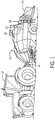
- a baler 10 that may be towed by a work vehicle, such as a tractor 12.
- a work vehicle such as a tractor 12.
- the tractor 12 includes a propulsion source that also drives a rotating power take off (PTO) 14 that is used to power systems of the baler 10.
- PTO rotating power take off
- the baler 10 gathers loose material, such as cut crop material, and forms bales that are compacted by a plunger mechanism 16.
- a knotter assembly 18 of the baler 10 is then utilized to tie the formed bale 20 with twine or other material before the bale 20 is ejected from the baling chamber.
- the knotter assembly 18 is driven through bale tying cycles by a drive system 22 that provides a single rotation output. Because the bales are individually completed, the knotter assembly 18 is driven intermittently, when a bale 20 is completely formed.
- the drive system 22 is timed to provide the required single rotation output in concert with cycling of the plunger mechanism 16 and includes an actuator 24 to trigger the drive system 22 to provide the required output.
- the location of the plunger mechanism 22 when a full bale 20 is produced is used to initiate the drive system 22 to drive the knotter assembly 18.
- the components of the baler 10 may be large, heavy and relatively slow moving. Accordingly, the drive system 22 accommodates this type of components in providing the transmission of intermittent power to drive the knotter assembly 18, once for each bale formed by the baler 10.
- the drive system 22 includes a drive unit 26.
- the drive unit 26 includes one or more components providing input power that are intermittently coupled to one or more components that receive and output power.
- an input element 28 is coupled with a power source such as the PTO 14, an actuator arm 30 coupled with an operator such as the actuator 24, and an output element 32 coupled with a driven mechanism such as the knotter mechanism 18.
- rotational power is intermittently transferred from the input element 28 to the output element 32 in a selected rotational amount, in response to actuation of the actuator arm 30.
- the output element 32 rotates through a single rotation as the selected rotational amount, in response to an actuation of the actuator arm 30.
- the actuator 24 may be any of a number of types of actuators configured to move the actuator arm 30 in time with the synched operation.
- the plunger mechanism 16 sets the cadence of the drive system 22.
- the actuator 24 is synched to move the actuator arm 30 in time with a stroke of the plunger mechanism 16. This provides a tying operation of the knotter mechanism 18 for each bale 20 produced by the baler 10.
- the actuator 24 may be operated through a mechanical linkage with the plunger mechanism 16, or through an electrical, pneumatic, hydraulic or other driving mechanism timed with the plunger mechanism 16. Timing may be accomplished through a mechanical link, timed teeth, electronic logic, or another method.
- the input element 28 is a rotating element, which in a number of variations may be a gear, sprocket, pulley, shaft, or other structure configured to connect the drive unit 26 with the application's power source, and to transmit power and motion into the drive unit 26.
- the input element 28 is an input shaft, and more specifically, a solid input shaft that is generally cylindrical in shape.
- the output element 32 is a rotating element, such as a gear, sprocket, pulley, shaft, or other structure configured to connect the drive unit 26 with the application's driven device and to transmit power and motion out of the drive unit 26.
- the output element 32 is an output shaft, and more specifically, a hollow output shaft that is generally a hollow cylinder in shape.
- the output element 32 may couple to one or more additional output components, which in the context of the baler example disclosed herein may be a knotter shaft 62.
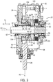
- the drive unit 26 includes a case 36 enclosing various components of the drive system 22 for protection and providing a lubricating oil reservoir 38 within which the internal components are set.
- the input element 28 extends through an opening 40 in the case 36 and is rotationally supported on the case by bearings 42.
- a gear, in the form of a bevel pinion 44 is formed on, or is connected to, the input element 28. Accordingly, rotational input is delivered into the case 36 through the input element 28 including the bevel pinion 44.
- a bevel gear 46 is rotationally disposed inside the case 36 and is supported on bearings 48, which are journaled on the output element 32.
- the bevel pinion 44 and the bevel gear 46 form a bevel gearset 49 that transfers rotational torque from rotation around the axis 50 of the input element 28 to rotation around the axis 52 of the output element 32.
- the axis 52 defines an axial direction 54 which is bi-directional and is parallel to, or coextensive with, the axis 52.
- the output element 32 extends completely through the case 34 and is rotationally supported on the case 34 by bearings 56 and 58.
- the output element 32 includes internal splines for connection with external splines of the knotter shaft 62 that is coupled with the knotter assembly 18, such the power flows through the mating splines 60 from the output element 32 to the knotter shaft 62.
- a splined coupler 64 is received over the output element 32 between the bearings 56 and 58. The splined coupler 64 is fixed in position on the output element 32 by mating splines 68 that extend in the axial direction 54.
- An engagement element (or first or driving engagement element) 72 includes an end 74 fixed to the bevel gear 46.
- the engagement element 72 includes an end 78 opposite the end 74.
- the end 78 forms a gear element 80 with external teeth or splines, terminal axial ends of which may be tapered or otherwise have camming surfaces to ease engagement.
- the gear element 80 rotates in concert with the input element 28 and the bevel gear 46.
- the PTO 14 drives these three elements (28, 46, 72) to rotate continuously when the tractor 12 and baler 10 are in operation and the PTO 14 is engaged, such that they may all be considered part of the power input to the drive system 22, in other words, they are all input components.
- Rotation and drive torque are intermittently delivered to the output element 32 through a synchronizing ring 82.
- the synchronizing ring 82 is generally annular in shape and is mounted on the output element 32, in the present example through the splined coupler 64.
- the synchronizing ring 82 is connected by mating splines 70 to rotate with the output element 32 and the splined coupler 64, and is slidable in the axial direction 54 relative to the output element 32 along the splines 70.
- the synchronizing ring 82 includes an annular shaped body 84 with a countersink 86 formed on its side 88 facing the bevel gear 46, creating an inside diameter having a surface 90 facing inward toward the axis 52 opposite from an outside diameter of the synchronizing ring 82.
- An engagement element (or second or driven engagement element) 92 is formed on the surface 90 and is engageable with the engagement element 72.
- the surface 90 includes a gear element 94 with teeth or splines that are configured to mesh with the teeth or splines of the gear element 80. Terminal ends of the teeth or splines in the gear element 94 may be tapered or otherwise have camming surfaces to ease engagement with the teeth or splines of the gear element 80.
- the synchronizing ring 82 is slidable on the splined coupler 64 in the axial direction 54.
- the gear element 94 meshes with the gear element 80 as shown in FIG. 4 , so that the engagement element 92 is engaged with the engagement element 72.
- the output element 32 is coupled to the input element 28 through the bevel gearset 49, the engagement elements 72, 92, the synchronizing ring 82 and the splined coupler 64, which forms a power path through the drive unit 26.
- the decoupling ring 96 is annular in shape and is disposed around the output element 32 adjacent the bevel gear 46.
- the decoupling ring 96 is supported on the bevel gear 46 and the engagement element 72 through a bearing 98.
- the bevel gear 46 and the engagement element 72 may rotate relative to the decoupling ring 96.
- the decoupling ring 96 is not required to rotate with the input element 28.
- the decoupling ring 96 is fixed in the axial direction 54 on the bearing 98.
- the decoupling ring 96 has an outer perimeter 100 with a lug 102 projecting radially outward from the outer perimeter 100 in a direction away from the axis 52.
- a trigger 104 is disposed in the case 34 and pivots on a shaft 106.
- the shaft 106 extends out of the case 34 and is connected with the actuator arm 30.
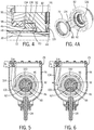
- the trigger 104 is moved between engagement with the lug 102 as shown in FIG. 5 and disengagement from the lug 102 as shown in FIG. 6 .
- the decoupling ring 96 is held from rotating and therefore, the input element 28 rotates while the decoupling ring 96 does not.
- the shaft 106 is rotated and the trigger 104 is moved to the position of FIG. 6 where the trigger is disengaged from the lug 102.
- The allows the decoupling ring 96 to rotate.
- a thrust ring 108 of wear resistant material is positioned between the bevel gear 46 and the decoupling ring 96.
- the thrust ring 108 When the trigger 104 releases the decoupling ring 96, the thrust ring 108 imparts rotational effort from the bevel gear 46 to the decoupling ring 96 so that the decoupling ring rotates with the input element 28.
- the thrust ring 108 may include a friction material surface in some examples.
- the decoupling ring 96 effects coupling and decoupling of the power path between the input element 28 and the output element 32 in response to actuation of the trigger 104 and through interaction with the synchronizing ring 82.
- the decoupling ring 96 includes decoupling features, which in the illustrated example take the form of a cam surface or ramp 110, and the synchronizing ring 82 includes decoupling features at an end face between the inner and outer diameters of the synchronizing ring, which in the illustrated example, are in the form of a complementary-shaped cam surface or ramp 112 that is shaped to mate with the ramp 110.
- the ramp 110 includes a ramp surface 114 facing in the axial direction 54 toward the synchronizing ring 82 and the ramp 112 includes a ramp surface 116 facing in the axial direction 54 toward the decoupling ring 96.
- the decoupling ring 96 and/or the synchronizing ring 82 may have multiple ramps 110, 112 respectively, formed around their circumference to distribute loads around the rings.
- An engage spring 115 e.g.
- a group of alternating conical springs is coupled to the splined coupler 64 (e.g., via a snap ring (not shown)) and a second spring 117 (e.g., one or more conical springs) is compressed between the case 34 and the synchronizing ring 82, collectively these springs 115, 117 biasing the synchronizing ring 82 toward the decoupling ring 96.
- This also forces the decoupling ring 96 against the thrust ring 108, helping maintain the decoupling ring 96 in a fixed axial position.
- the engage spring 115 also provides an axial force tending to mate the teeth or splines of the engagement element 92 and the engagement element 72.
- the spring 115 also aids in controlling the frictional content of the synchronizing ring 82 to help impart a rotational difference of the synchronizing ring 82 with respect to the decoupling ring 96.
- the ramp 110 includes an end 118, which is the part of the ramp 110 that projects toward the synchronizing ring 82 the least distance in the axial direction.
- the ramp 110 includes an end 120, which is the part of the ramp 110 that projects toward the synchronizing ring 82 the greatest distance in the axial direction.
- the ramp 112 includes an end 122, which is the part of the ramp 112 that projects toward the decoupling ring 96 the greatest distance in the axial direction.
- the ramp 112 includes an end 124, which is the part of the ramp 112 that projects toward the decoupling ring 96 the greatest distance in the axial direction.
- the ramped surface 114 slides along the ramp surface 116, as shown in FIG. 8 .
- the gap 126 is reduced as the engagement elements 72, 92 engage with the gear element 94 meshing with the gear element 80, and the synchronizing ring 82 is driven to rotate by the engagement element 72.
- the engage spring 115 is decompressed.
- the engagement elements 72, 92 fully engage, and, as shown in FIG. 9 , the end 122 of ramp 112 registers with the end 118 of ramp 110.
- the input element 28 is coupled with the output element 32 and rotates therewith, as shown in FIGS. 3A and 4 .
- the power flow from the input element 28 to the knotter shaft 62 is shown by the dot-dash path in FIG. 3A during the intermittent coupling thereof.
- rotational power flows through the input element 28 to the bevel gear 46 through its coupling with the bevel pinion 46.
- the bevel gear 46 rotates the engagement element 72 to which it is splined.
- the gear element 80 of the engagement element 72 meshes with the engagement element 92/gear element 94 of the synchronizer ring 82, which is splined to the output element 32 by the splined coupler 64.
- the output element 32 in turn rotates the knotter shaft 62 through the mating splines 60.
- the trigger 104 is biased toward the decoupling ring 96 so that once the lug 102 clears the trigger 104, the trigger 104 is positioned against the decoupling ring 96 so that when one revolution is complete, the lug 102 reengages the trigger 104 and the decoupling ring 96 is again stopped from rotating, as shown in FIG. 5 .
- Disengagement of the engagement elements 72, 92 and therefore, disengagement of the output element 32 from the input element 28 is initiated by stopping rotation of the decoupling ring 96.
- the synchronizing ring 82 initially continues to rotate under operation of the engaged engagement elements 72, 92.
- Stopping rotation of the decoupling ring 96 drives the synchronizing ring 82 in the axial direction 54 via the ramps 110, 112.
- the ramp surface 116 slides along the ramp surface 114 forcing the synchronizing ring 82 away from the decoupling ring 96 and reopening the gap 126.
- the engagement elements 72, 92 disengage, as shown in FIG. 3 , and as the synchronizing ring returns to the position of FIG. 7 , the synchronizing ring 82 stops rotation at the same rotational position at which it began moving. Accordingly, the output element 32 makes one revolution per actuation of the trigger 104.
- the output element 32 may be rotated intermittently an amount other than a single revolution by providing multiple lugs 102 such as for a fraction of a rotation, or by holding the trigger 104 disengaged from the decoupling ring 96 by the actuator 24 such as for a selected number of rotations. In other embodiments, any preferred amount of rotation may be provided through a combination of lugs 102 and actuation of the trigger 104.
- a soft decoupling is provided which avoids impact shocks and force spikes in the drive system 22 as the decoupling ring 96 comes to an abrupt stop. Disengagement using the ramps 110, 112 avoids binds as the engagement elements 72, 92 disengage under load.
- the drive unit 26 includes a brake 128, where decoupling action of the drive system 22 applies the brake 128.
- a number of brake disks 130 are positioned axially between the synchronizing ring 82 and a stop 132.
- the synchronizing ring 82 includes an annular extension 124 that extends in the axial direction 54 through the brake discs 130, which are also annular in shape.
- the stop 132 is in the form of an annular plate disposed on annular extension 124. Axial movement of the stop 132 is restricted, such as by the case 34.
- the brake 128 When the synchronizing ring 82 moves axially toward the stop 132 under operation of the ramps 110 and 112, the brake 128 is incrementally applied to slow the synchronizing ring 82, the output element 32, and the connected components. In applications such as the baler 10, where large heavy components of the knotter assembly 18 are driven to move, the brake 128 provides a mechanism to slow movement as the engagement elements 72, 92 operate through disengagement. When the drive system 22 is decoupled, free rotation of the synchronizing ring 82 is prevented by the brake 128. In a number of examples, by holding the synchronizing ring 82, the brake 128 holds the output element 32 in position when the engagement elements 72, 92 are disengaged, which holds the connected components such as the knotter assembly 18 in its starting position. The brake 128 is set in the reservoir 38 and, therefore, protected by the case 34 and lubricated by the contained lubrication oil.
- the synchronizing ring 82 may have one engagement orientation or a discrete number of engagement orientations per revolution in which the synchronizing ring 82 is synchronized with the decoupling ring 96.
- the synchronizing ring 82 and the decoupling ring 96 may be required to be in the one engagement orientation (or discrete number of engagement orientations) to be properly oriented so that the teeth or splines of the gear element 80 may align and engage with teeth or splines of the gear element 94.
- the synchronizing ring 82 has a single alignment lug 134 that is configured to mate with a single alignment recess 136 in the engagement element 72, thus requiring a single engagement orientation of the synchronizing ring 82.
- the alignment lug 134 must align with the alignment recess 136.
- the synchronizing ring 82 and the engagement element 72 could be rotated into other engagement orientations.
- the assembly included a second pairing of alignment lug and recess of the same configuration at angularly spaced 180 degrees from the alignment lug 134 and alignment recess 136, then coupling could occur in either of two engagement orientations, and so for additional alignment pairings of the same shape with equal angular spacings.
- the configuration and the male-female orientation of the alignment features could different, for example, with the alignment lug being located on the engagement element 72 and the alignment recess being located in the synchronizing ring 82.
- either alignment feature it is possible for either alignment feature to be made a part of the decoupling ring 96 rather than the engagement element 72.
- the decoupling ring 96 is held rotationally fixed until the trigger 104 is disengaged, and the synchronizing ring 82 may be held rotationally fixed until the brake 128 is released.
- the trigger 104 and the brake 128 may be actuated to release the decoupling ring 96 and the synchronizing ring 82 simultaneously or sequentially.
- the decoupling ring 96 will begin to rotate up to the input speed (and may or may not reach it), and the synchronizing ring 82, which is biased by the springs 115, 117 toward and in contact with the now rotating decoupling ring 96, will begin to rotate as well.
- the alignment features 134, 136 may index or rotate slightly until the alignment features 134, 136 align and mate.
- This relative rotational difference may occur naturally in the example embodiment in which the alignment features are located in one continuously rotating part (e.g., the engagement element 72) and one intermittently rotating part (e.g., the synchronizing ring 82).
- relative rotation or indexing between the alignment features may be encouraged by controlling the timing in which the brake 128 is released relative to the release of the trigger 104 (e.g., by slightly delaying brake release) and/or applying a certain frictional load tending to resist rotation by the synchronizing ring 82, which, in either case, would affect the rotational speed of the synchronizing ring 82 relative to the decoupling ring 96.
- Mechanical features such as spring 117, can impart a different frictional load on the synchronizing ring 82, and thereby the time by which the synchronizing ring 82 will speed up, which will effect a relative rotation with respect to the engagement element 72 or the decoupling ring 96 as the case may be.
- a drive system includes a rotating input element and an output element that is alternatively coupled with the input element to rotate therewith or is decoupled from the input element to not rotate therewith, through operation of a decoupling bring and a synchronizing ring.
- Rotation of the output element is timed to an operation of the machine within which the drive system transmits power.
- the output element begins rotating and stops at the same rotational position. Intermittent power transmission is provided in single rotation increments, or in other increments. Coupling of power from the input to the output through the synchronizer clutch is established only upon two conditions being met, namely, the cooperative alignment of the alignment features, and cooperative alignment of the decoupling features.
- the peaks of the teeth or splines of the engagement element align with the valleys between the teeth or splines of the synchronizing ring. Then, with the decoupling features oriented so that ramps slide into contact with one another, the teeth and splines are slid axially and intermeshed within each other.
- This two-step or two-key arrangement ensures proper indexing and engagement of the mating teeth or splines during coupling of the input to the output by the synchronizer clutch.
Landscapes
- Engineering & Computer Science (AREA)
- General Engineering & Computer Science (AREA)
- Mechanical Engineering (AREA)
- Life Sciences & Earth Sciences (AREA)
- Environmental Sciences (AREA)
- Chemical & Material Sciences (AREA)
- Combustion & Propulsion (AREA)
- Transportation (AREA)
- Mechanical Operated Clutches (AREA)
- Transmission Devices (AREA)
Claims (11)
- Intermittierendes Antriebssystem, Folgendes umfassend:eine drehbare Ausgangskomponente (32);eine drehbare Eingangskomponente (28), die ein Antriebseingriffselement (72) umfasst;einen Synchronisierer, der einen Synchronisierring (82) umfasst, der mit dem Ausgangselement (32) gekoppelt ist, um sich damit zu drehen, wobei der Synchronisierring (82) ein angetriebenes Eingriffselement (92) aufweist, das dazu ausgelegt ist, selektiv in das Antriebseingriffselement (72) einzugreifen, wobei der Synchronisierring (82) ein Ausrichtungsmerkmal (134) aufweist, das dazu ausgelegt ist, das Antriebseingriffselement (72) drehend mit dem angetriebenen Eingriffselement (92) auszurichten, und einen Entkopplungsring (96) umfasst, der selektiv mit der Eingangskomponente (28) gekoppelt ist,dadurch gekennzeichnet, dassder Synchronisierring (82) ein Entkopplungsmerkmal (112) aufweist, das dazu ausgelegt ist, das Antriebseingriffselement (72) selektiv vom angetriebenen Eingriffselement (92) zu lösen; undder Entkopplungsring (96) ein Entkopplungsmerkmal (110) aufweist, das dazu ausgelegt ist, selektiv in das Entkopplungsmerkmal (112) des Synchronisierrings (82) einzugreifen;wobei das Antriebseingriffselement (72) nur in das angetriebene Eingriffselement (92) eingreift, wenn sowohl das Ausrichtungsmerkmal (134) drehbar ausgerichtet ist, um das Antriebseingriffselement (72) mit dem angetriebenen Eingriffselement (92) auszurichten, als auch die Entkopplungsmerkmale (110, 112) drehbar ausgerichtet sind, um zuzulassen, dass das Antriebseingriffselement (72) in das angetriebene Eingriffselement (92) eingreift.
- Intermittierendes Antriebssystem nach Anspruch 1, wobei der Synchronisierer derart ausgelegt ist, dass das Antriebseingriffselement (72) und das angetriebene Eingriffselement (92) innerhalb einer einzelnen Drehung der Ausgangskomponente (32) ineinander eingreifen und sich voneinander lösen.
- Intermittierendes Antriebssystem nach Anspruch 1 oder 2, wobei der Synchronisierring (82) einen Innendurchmesser und einen Außendurchmesser aufweist; und
wobei das angetriebene Eingriffselement (92) ein Satz Zähne oder Rippen ist, die entlang des Innendurchmessers angeordnet sind, wobei das Ausrichtungsmerkmal (134) eine oder mehrere Laschen oder Aussparungen ist, die sich zwischen dem Innendurchmesser und dem Außendurchmesser befinden und das Entkopplungsmerkmal (112) eine oder mehrere Rampenflächen ist, die sich zwischen dem Innendurchmesser und dem Außendurchmesser befinden. - Intermittierendes Antriebssystem nach einem der vorstehenden Ansprüche, wobei der Synchronisierer ferner den Entkopplungsring (96) umfasst, wobei das Entkopplungsmerkmal (110) des Entkopplungsrings (96) dazu ausgelegt ist, sich mit dem Entkopplungsmerkmal (112) des Synchronisierrings (82) zu verbinden.
- Intermittierendes Antriebssystem nach einem der vorstehenden Ansprüche, wobei die Entkopplungsmerkmale (110, 112) des Synchronisierrings (82) und des Entkopplungsrings (96) zueinander passende Rampenflächen (114, 116) sind.
- Intermittierendes Antriebssystem nach einem der vorstehenden Ansprüche, wobei die Rampenflächen (114, 116) dazu ausgelegt sind, das angetriebene Eingriffselement (92) vom Antriebseingriffselement (72) zu lösen, indem die Rampenflächen (114, 116) gegeneinander verschoben werden, um den Synchronisierring (82) vom Entkopplungsring (96) wegzubewegen.
- Intermittierendes Antriebssystem nach einem der vorstehenden Ansprüche, wobei der Synchronisierring (82) entlang einer Drehachse beweglich und um die Drehachse in Bezug zum Entkopplungsring (96) drehbar ist, wenn das Antriebseingriffselement (72) und das angetriebene Eingriffselement (92) ineinander eingreifen bzw. voneinander gelöst sind; und
ferner eine Feder (115, 117) umfassend, die den Synchronisierring zum Entkopplungsring (96) hin vorspannt. - Intermittierendes Antriebssystem nach einem der vorstehenden Ansprüche, ferner eine Bremse (128) umfassend, die die Drehung des Synchronisierrings (82) verhindert.
- Intermittierendes Antriebssystem nach einem der vorstehenden Ansprüche, wobei der Entkopplungsring (96) eine Lasche (102) aufweist, die beim Eingriff die Drehung des Entkopplungsrings (96) und das Koppeln des Antriebseingriffsglieds in das angetriebene Eingriffsglied verhindert.
- Intermittierendes Antriebssystem nach einem der vorstehenden Ansprüche, ferner einen Auslöser (104) umfassend, der selektiv in die Lasche (102) des Entkopplungsrings (96) eingreifbar ist;
wobei, wenn die Lasche (102) vom Auslöser (104) gelöst wird, sich der Synchronisierring (82) und das Ausgangselement (32) durch das Betätigen des Auslösers (104) durch eine einzelne Drehung drehen; und
wobei bei der einzelnen Drehung das Ausgangselement (32) an einer Drehposition beginnt und an der Drehposition endet. - Intermittierendes Antriebssystem nach einem der vorstehenden Ansprüche, wobei die Eingangskomponente (28) ein Ausrichtungsmerkmal (136) umfasst, das mit dem Ausrichtungsmerkmal (134) des Synchronisierrings (82) verbindbar ist; und
wobei die Ausrichtungsmerkmale (134, 136) der Eingangskomponente (28) und des Synchronisierrings (82) eine oder mehrere zueinander passende Laschen-und-Aussparungsanordnungen sind.
Priority Applications (1)
| Application Number | Priority Date | Filing Date | Title |
|---|---|---|---|
| PL18201577T PL3524839T3 (pl) | 2017-10-25 | 2018-10-19 | Układ napędowy dla przerywanego obracania |
Applications Claiming Priority (2)
| Application Number | Priority Date | Filing Date | Title |
|---|---|---|---|
| US201762576997P | 2017-10-25 | 2017-10-25 | |
| US16/155,171 US10701866B2 (en) | 2017-10-25 | 2018-10-09 | Drive system for intermittent rotation output |
Publications (3)
| Publication Number | Publication Date |
|---|---|
| EP3524839A2 EP3524839A2 (de) | 2019-08-14 |
| EP3524839A3 EP3524839A3 (de) | 2019-11-20 |
| EP3524839B1 true EP3524839B1 (de) | 2021-03-03 |
Family
ID=66168980
Family Applications (1)
| Application Number | Title | Priority Date | Filing Date |
|---|---|---|---|
| EP18201577.6A Active EP3524839B1 (de) | 2017-10-25 | 2018-10-19 | Nietsystem für intermittierende rotationsausgabe |
Country Status (3)
| Country | Link |
|---|---|
| US (1) | US10701866B2 (de) |
| EP (1) | EP3524839B1 (de) |
| PL (1) | PL3524839T3 (de) |
Families Citing this family (7)
| Publication number | Priority date | Publication date | Assignee | Title |
|---|---|---|---|---|
| US11782453B2 (en) | 2021-02-16 | 2023-10-10 | Deere & Company | Image-based position assessment of agricultural machine components |
| EP4067245B1 (de) * | 2021-03-31 | 2025-02-19 | Becton Dickinson Rowa Germany GmbH | Vorrats- und abgabestation für einen blisterautomaten |
| US11690322B1 (en) * | 2022-06-06 | 2023-07-04 | Deere & Company | Baler independent needle drive |
| GB202215449D0 (en) * | 2022-10-19 | 2022-11-30 | Kuhn Geldrop Bv | One-turn coupling |
| JP2025535863A (ja) * | 2022-11-15 | 2025-10-30 | ジーケーエヌ オートモーティブ リミテッド | 選択接続組立体を伴う駆動系構成要素 |
| US12025189B1 (en) * | 2023-02-07 | 2024-07-02 | Cnh Industrial America Llc | In-line compact baler declutch mechanism |
| US12571433B2 (en) * | 2024-04-16 | 2026-03-10 | Timotion Technology Co., Ltd. | Electronic control clutch structure of an actuator device |
Family Cites Families (22)
| Publication number | Priority date | Publication date | Assignee | Title |
|---|---|---|---|---|
| US2566054A (en) | 1945-10-10 | 1951-08-28 | Griffith L Burkett | Baler wire tying mechanism |
| US2667252A (en) | 1950-03-21 | 1954-01-26 | Karl Maybach | Claw clutch |
| US2869697A (en) | 1954-08-18 | 1959-01-20 | Tiltman Langley Ltd | Power transmission clutch |
| NL209669A (de) | 1956-03-27 | |||
| IT1070120B (it) | 1975-09-11 | 1985-03-25 | Walterscheid Gmbh Jean | Innesto a ruota libera per la limitazione della coppia trasmessa da un motore ad una macchina operatrice |
| DE3528591A1 (de) | 1984-12-22 | 1986-07-10 | Jean Walterscheid Gmbh, 5204 Lohmar | In antriebseinrichtung abschaltbarer freilauf |
| DE3535264A1 (de) | 1985-10-03 | 1987-04-09 | Walterscheid Gmbh Jean | In abtriebsrichtung abschaltbarer freilauf |
| DE19803835C2 (de) | 1998-01-31 | 2002-06-20 | Krone Bernhard Gmbh Maschf | Aufsammelkolbenpresse |
| DE102008049978A1 (de) | 2008-07-03 | 2010-01-07 | Schaeffler Kg | Schalteinheit mit Kupplungskörper |
| US8042642B2 (en) | 2008-08-14 | 2011-10-25 | American Axle & Manufacturing, Inc. | Motor vehicle with disconnectable all-wheel drive system |
| DE102009037026B4 (de) | 2009-08-13 | 2011-07-28 | GKN Walterscheid GmbH, 53797 | Drehmomentbegrenzungskupplung |
| DE102010045898A1 (de) * | 2010-04-12 | 2011-10-13 | Magna Powertrain Ag & Co Kg | Kopplungsanordnung |
| CN103596794B (zh) | 2011-04-20 | 2017-08-25 | Gkn 动力传动系统有限责任公司 | 动力传输单元 |
| JP2013217491A (ja) * | 2012-03-14 | 2013-10-24 | Aisin Seiki Co Ltd | 自動変速機用ドグクラッチ |
| BE1020595A3 (nl) | 2012-03-26 | 2014-01-07 | Cnh Belgium Nv | Enkelvoudige revolutiekoppeling, aandrijfsysteem en vierkante balenpers met een dergelijke koppeling en gebruik van een dergelijke koppeling, aandrijfsysteem of balenpers. |
| US8469854B1 (en) | 2012-05-15 | 2013-06-25 | American Axle & Manufacturing, Inc. | Disconnectable driveline for all-wheel drive vehicle |
| DE102012210287A1 (de) * | 2012-06-19 | 2013-12-19 | Zf Friedrichshafen Ag | Verbindungsvorrichtung und Getriebe für einen Fahrzeugantriebsstrang sowie Verfahren zur Betätigung einer solchen Verbindungsvorrichtung |
| JP5817760B2 (ja) * | 2013-03-04 | 2015-11-18 | 株式会社豊田自動織機 | スクロール型圧縮機 |
| JP5790701B2 (ja) * | 2013-04-15 | 2015-10-07 | 株式会社豊田中央研究所 | クラッチ機構及び変速機 |
| US9585311B2 (en) | 2014-09-23 | 2017-03-07 | Deere & Company | Clutch mechanism for a baler |
| US9302581B1 (en) | 2014-10-10 | 2016-04-05 | American Axle & Manufacturing, Inc. | All-wheel drive driveline with disconnecting axle |
| KR102462590B1 (ko) * | 2017-05-16 | 2022-11-04 | 현대자동차주식회사 | 변속기의 동기장치 |
-
2018
- 2018-10-09 US US16/155,171 patent/US10701866B2/en active Active
- 2018-10-19 PL PL18201577T patent/PL3524839T3/pl unknown
- 2018-10-19 EP EP18201577.6A patent/EP3524839B1/de active Active
Non-Patent Citations (1)
| Title |
|---|
| None * |
Also Published As
| Publication number | Publication date |
|---|---|
| US10701866B2 (en) | 2020-07-07 |
| PL3524839T3 (pl) | 2021-07-19 |
| US20190116735A1 (en) | 2019-04-25 |
| EP3524839A3 (de) | 2019-11-20 |
| EP3524839A2 (de) | 2019-08-14 |
Similar Documents
| Publication | Publication Date | Title |
|---|---|---|
| EP3524839B1 (de) | Nietsystem für intermittierende rotationsausgabe | |
| EP1518059B1 (de) | Synchroniserte getriebeschaltung mit hydraulischer betätigung | |
| EP1499811A2 (de) | Kupplungsaggregat | |
| US20110214532A1 (en) | Double clutch with a differentiator | |
| US9574619B1 (en) | Pawl grounding clutch with synchronizer | |
| DE69232337T2 (de) | Automatische Kupplung mit dazugehörigem automatischem Getriebe und Steuerungsverfahren | |
| WO2008128599A1 (de) | Drehmomenten-/drehzahldifferenzabhängige kupplungsbetätigungseinheit für motorangetriebene fahrzeuge | |
| DE102007050235A1 (de) | Antriebssystem für ein Fahrzeug | |
| AT507523A2 (de) | Parallelhybridantrieb für ein kraftfahrzeug | |
| US20160243936A1 (en) | Transfer | |
| DE10016607A1 (de) | Doppelkupplungsanordnung | |
| DE102010012610A1 (de) | Schaltbare Magnetkupplung und Verfahren zum Betätigen einer schaltbaren Magnetkupplung | |
| DE102005027610A1 (de) | Drehmomentübertragungseinrichtung und Antriebsstrang mit dieser | |
| EP2932130A2 (de) | Betätigungsvorrichtung für eine kupplung, kupplung, elektrisches fahrmodul und verfahren zur montage einer kupplung | |
| WO2019096478A1 (de) | Schaltgetriebe und elektroantrieb mit einem schaltgetriebe | |
| EP3423737A1 (de) | Schaltgetriebe mit aktuatoranordnung, verfahren zum steuern des schaltgetriebes und elektroantrieb mit schaltgetriebe | |
| EP1766252B1 (de) | Verbesserung von drehsynchronisationsanordnungen oder diese betreffend | |
| EP1753966B1 (de) | Kupplung | |
| EP1668268A1 (de) | Hilfsaggregatantrieb für einen fahrzeugmotor mit zu- und ent koppelbarer riemenscheibe sowie hilfsaggregat | |
| DE939846C (de) | Ausrückeinrichtung für Schubschraubtrieb - Anlasser von Brennkraftmaschinen | |
| DE102008054413B4 (de) | Torsionsschwingungsdämpferanordnung | |
| WO2015000811A1 (de) | Kupplung | |
| AT7579U1 (de) | Klauenkupplung | |
| DE102005015617A1 (de) | Durch Elektromotor eingerückte Kupplung mit einem Schleppdrehmomentaktuator | |
| DE102008002252A1 (de) | Kompressorkupplung |
Legal Events
| Date | Code | Title | Description |
|---|---|---|---|
| PUAI | Public reference made under article 153(3) epc to a published international application that has entered the european phase |
Free format text: ORIGINAL CODE: 0009012 |
|
| STAA | Information on the status of an ep patent application or granted ep patent |
Free format text: STATUS: THE APPLICATION HAS BEEN PUBLISHED |
|
| AK | Designated contracting states |
Kind code of ref document: A2 Designated state(s): AL AT BE BG CH CY CZ DE DK EE ES FI FR GB GR HR HU IE IS IT LI LT LU LV MC MK MT NL NO PL PT RO RS SE SI SK SM TR |
|
| AX | Request for extension of the european patent |
Extension state: BA ME |
|
| PUAL | Search report despatched |
Free format text: ORIGINAL CODE: 0009013 |
|
| AK | Designated contracting states |
Kind code of ref document: A3 Designated state(s): AL AT BE BG CH CY CZ DE DK EE ES FI FR GB GR HR HU IE IS IT LI LT LU LV MC MK MT NL NO PL PT RO RS SE SI SK SM TR |
|
| AX | Request for extension of the european patent |
Extension state: BA ME |
|
| RIC1 | Information provided on ipc code assigned before grant |
Ipc: F16D 43/26 20060101ALI20191011BHEP Ipc: B60K 17/28 20060101ALI20191011BHEP Ipc: F16D 11/14 20060101AFI20191011BHEP Ipc: A01F 15/00 20060101ALI20191011BHEP Ipc: F16D 43/202 20060101ALI20191011BHEP |
|
| STAA | Information on the status of an ep patent application or granted ep patent |
Free format text: STATUS: REQUEST FOR EXAMINATION WAS MADE |
|
| 17P | Request for examination filed |
Effective date: 20200520 |
|
| RBV | Designated contracting states (corrected) |
Designated state(s): AL AT BE BG CH CY CZ DE DK EE ES FI FR GB GR HR HU IE IS IT LI LT LU LV MC MK MT NL NO PL PT RO RS SE SI SK SM TR |
|
| GRAP | Despatch of communication of intention to grant a patent |
Free format text: ORIGINAL CODE: EPIDOSNIGR1 |
|
| STAA | Information on the status of an ep patent application or granted ep patent |
Free format text: STATUS: GRANT OF PATENT IS INTENDED |
|
| INTG | Intention to grant announced |
Effective date: 20201015 |
|
| GRAS | Grant fee paid |
Free format text: ORIGINAL CODE: EPIDOSNIGR3 |
|
| GRAA | (expected) grant |
Free format text: ORIGINAL CODE: 0009210 |
|
| STAA | Information on the status of an ep patent application or granted ep patent |
Free format text: STATUS: THE PATENT HAS BEEN GRANTED |
|
| AK | Designated contracting states |
Kind code of ref document: B1 Designated state(s): AL AT BE BG CH CY CZ DE DK EE ES FI FR GB GR HR HU IE IS IT LI LT LU LV MC MK MT NL NO PL PT RO RS SE SI SK SM TR |
|
| REG | Reference to a national code |
Ref country code: GB Ref legal event code: FG4D |
|
| REG | Reference to a national code |
Ref country code: AT Ref legal event code: REF Ref document number: 1367534 Country of ref document: AT Kind code of ref document: T Effective date: 20210315 Ref country code: CH Ref legal event code: EP |
|
| REG | Reference to a national code |
Ref country code: DE Ref legal event code: R096 Ref document number: 602018013307 Country of ref document: DE |
|
| REG | Reference to a national code |
Ref country code: IE Ref legal event code: FG4D |
|
| REG | Reference to a national code |
Ref country code: LT Ref legal event code: MG9D |
|
| PG25 | Lapsed in a contracting state [announced via postgrant information from national office to epo] |
Ref country code: LT Free format text: LAPSE BECAUSE OF FAILURE TO SUBMIT A TRANSLATION OF THE DESCRIPTION OR TO PAY THE FEE WITHIN THE PRESCRIBED TIME-LIMIT Effective date: 20210303 Ref country code: NO Free format text: LAPSE BECAUSE OF FAILURE TO SUBMIT A TRANSLATION OF THE DESCRIPTION OR TO PAY THE FEE WITHIN THE PRESCRIBED TIME-LIMIT Effective date: 20210603 Ref country code: GR Free format text: LAPSE BECAUSE OF FAILURE TO SUBMIT A TRANSLATION OF THE DESCRIPTION OR TO PAY THE FEE WITHIN THE PRESCRIBED TIME-LIMIT Effective date: 20210604 Ref country code: FI Free format text: LAPSE BECAUSE OF FAILURE TO SUBMIT A TRANSLATION OF THE DESCRIPTION OR TO PAY THE FEE WITHIN THE PRESCRIBED TIME-LIMIT Effective date: 20210303 Ref country code: HR Free format text: LAPSE BECAUSE OF FAILURE TO SUBMIT A TRANSLATION OF THE DESCRIPTION OR TO PAY THE FEE WITHIN THE PRESCRIBED TIME-LIMIT Effective date: 20210303 Ref country code: BG Free format text: LAPSE BECAUSE OF FAILURE TO SUBMIT A TRANSLATION OF THE DESCRIPTION OR TO PAY THE FEE WITHIN THE PRESCRIBED TIME-LIMIT Effective date: 20210603 |
|
| REG | Reference to a national code |
Ref country code: NL Ref legal event code: MP Effective date: 20210303 |
|
| REG | Reference to a national code |
Ref country code: AT Ref legal event code: MK05 Ref document number: 1367534 Country of ref document: AT Kind code of ref document: T Effective date: 20210303 |
|
| PG25 | Lapsed in a contracting state [announced via postgrant information from national office to epo] |
Ref country code: SE Free format text: LAPSE BECAUSE OF FAILURE TO SUBMIT A TRANSLATION OF THE DESCRIPTION OR TO PAY THE FEE WITHIN THE PRESCRIBED TIME-LIMIT Effective date: 20210303 Ref country code: LV Free format text: LAPSE BECAUSE OF FAILURE TO SUBMIT A TRANSLATION OF THE DESCRIPTION OR TO PAY THE FEE WITHIN THE PRESCRIBED TIME-LIMIT Effective date: 20210303 Ref country code: RS Free format text: LAPSE BECAUSE OF FAILURE TO SUBMIT A TRANSLATION OF THE DESCRIPTION OR TO PAY THE FEE WITHIN THE PRESCRIBED TIME-LIMIT Effective date: 20210303 |
|
| PG25 | Lapsed in a contracting state [announced via postgrant information from national office to epo] |
Ref country code: NL Free format text: LAPSE BECAUSE OF FAILURE TO SUBMIT A TRANSLATION OF THE DESCRIPTION OR TO PAY THE FEE WITHIN THE PRESCRIBED TIME-LIMIT Effective date: 20210303 |
|
| PG25 | Lapsed in a contracting state [announced via postgrant information from national office to epo] |
Ref country code: SM Free format text: LAPSE BECAUSE OF FAILURE TO SUBMIT A TRANSLATION OF THE DESCRIPTION OR TO PAY THE FEE WITHIN THE PRESCRIBED TIME-LIMIT Effective date: 20210303 Ref country code: AT Free format text: LAPSE BECAUSE OF FAILURE TO SUBMIT A TRANSLATION OF THE DESCRIPTION OR TO PAY THE FEE WITHIN THE PRESCRIBED TIME-LIMIT Effective date: 20210303 Ref country code: EE Free format text: LAPSE BECAUSE OF FAILURE TO SUBMIT A TRANSLATION OF THE DESCRIPTION OR TO PAY THE FEE WITHIN THE PRESCRIBED TIME-LIMIT Effective date: 20210303 Ref country code: CZ Free format text: LAPSE BECAUSE OF FAILURE TO SUBMIT A TRANSLATION OF THE DESCRIPTION OR TO PAY THE FEE WITHIN THE PRESCRIBED TIME-LIMIT Effective date: 20210303 |
|
| PG25 | Lapsed in a contracting state [announced via postgrant information from national office to epo] |
Ref country code: PT Free format text: LAPSE BECAUSE OF FAILURE TO SUBMIT A TRANSLATION OF THE DESCRIPTION OR TO PAY THE FEE WITHIN THE PRESCRIBED TIME-LIMIT Effective date: 20210705 Ref country code: SK Free format text: LAPSE BECAUSE OF FAILURE TO SUBMIT A TRANSLATION OF THE DESCRIPTION OR TO PAY THE FEE WITHIN THE PRESCRIBED TIME-LIMIT Effective date: 20210303 Ref country code: RO Free format text: LAPSE BECAUSE OF FAILURE TO SUBMIT A TRANSLATION OF THE DESCRIPTION OR TO PAY THE FEE WITHIN THE PRESCRIBED TIME-LIMIT Effective date: 20210303 Ref country code: IS Free format text: LAPSE BECAUSE OF FAILURE TO SUBMIT A TRANSLATION OF THE DESCRIPTION OR TO PAY THE FEE WITHIN THE PRESCRIBED TIME-LIMIT Effective date: 20210703 |
|
| REG | Reference to a national code |
Ref country code: DE Ref legal event code: R097 Ref document number: 602018013307 Country of ref document: DE |
|
| PLBE | No opposition filed within time limit |
Free format text: ORIGINAL CODE: 0009261 |
|
| STAA | Information on the status of an ep patent application or granted ep patent |
Free format text: STATUS: NO OPPOSITION FILED WITHIN TIME LIMIT |
|
| PG25 | Lapsed in a contracting state [announced via postgrant information from national office to epo] |
Ref country code: ES Free format text: LAPSE BECAUSE OF FAILURE TO SUBMIT A TRANSLATION OF THE DESCRIPTION OR TO PAY THE FEE WITHIN THE PRESCRIBED TIME-LIMIT Effective date: 20210303 Ref country code: AL Free format text: LAPSE BECAUSE OF FAILURE TO SUBMIT A TRANSLATION OF THE DESCRIPTION OR TO PAY THE FEE WITHIN THE PRESCRIBED TIME-LIMIT Effective date: 20210303 Ref country code: DK Free format text: LAPSE BECAUSE OF FAILURE TO SUBMIT A TRANSLATION OF THE DESCRIPTION OR TO PAY THE FEE WITHIN THE PRESCRIBED TIME-LIMIT Effective date: 20210303 |
|
| 26N | No opposition filed |
Effective date: 20211206 |
|
| PG25 | Lapsed in a contracting state [announced via postgrant information from national office to epo] |
Ref country code: SI Free format text: LAPSE BECAUSE OF FAILURE TO SUBMIT A TRANSLATION OF THE DESCRIPTION OR TO PAY THE FEE WITHIN THE PRESCRIBED TIME-LIMIT Effective date: 20210303 |
|
| PG25 | Lapsed in a contracting state [announced via postgrant information from national office to epo] |
Ref country code: IT Free format text: LAPSE BECAUSE OF FAILURE TO SUBMIT A TRANSLATION OF THE DESCRIPTION OR TO PAY THE FEE WITHIN THE PRESCRIBED TIME-LIMIT Effective date: 20210303 |
|
| REG | Reference to a national code |
Ref country code: CH Ref legal event code: PL |
|
| PG25 | Lapsed in a contracting state [announced via postgrant information from national office to epo] |
Ref country code: IS Free format text: LAPSE BECAUSE OF FAILURE TO SUBMIT A TRANSLATION OF THE DESCRIPTION OR TO PAY THE FEE WITHIN THE PRESCRIBED TIME-LIMIT Effective date: 20210703 |
|
| REG | Reference to a national code |
Ref country code: BE Ref legal event code: MM Effective date: 20211031 |
|
| PG25 | Lapsed in a contracting state [announced via postgrant information from national office to epo] |
Ref country code: MC Free format text: LAPSE BECAUSE OF FAILURE TO SUBMIT A TRANSLATION OF THE DESCRIPTION OR TO PAY THE FEE WITHIN THE PRESCRIBED TIME-LIMIT Effective date: 20210303 |
|
| PG25 | Lapsed in a contracting state [announced via postgrant information from national office to epo] |
Ref country code: LU Free format text: LAPSE BECAUSE OF NON-PAYMENT OF DUE FEES Effective date: 20211019 Ref country code: BE Free format text: LAPSE BECAUSE OF NON-PAYMENT OF DUE FEES Effective date: 20211031 |
|
| PG25 | Lapsed in a contracting state [announced via postgrant information from national office to epo] |
Ref country code: LI Free format text: LAPSE BECAUSE OF NON-PAYMENT OF DUE FEES Effective date: 20211031 Ref country code: CH Free format text: LAPSE BECAUSE OF NON-PAYMENT OF DUE FEES Effective date: 20211031 |
|
| GBPC | Gb: european patent ceased through non-payment of renewal fee |
Effective date: 20221019 |
|
| PG25 | Lapsed in a contracting state [announced via postgrant information from national office to epo] |
Ref country code: CY Free format text: LAPSE BECAUSE OF FAILURE TO SUBMIT A TRANSLATION OF THE DESCRIPTION OR TO PAY THE FEE WITHIN THE PRESCRIBED TIME-LIMIT Effective date: 20210303 |
|
| PG25 | Lapsed in a contracting state [announced via postgrant information from national office to epo] |
Ref country code: HU Free format text: LAPSE BECAUSE OF FAILURE TO SUBMIT A TRANSLATION OF THE DESCRIPTION OR TO PAY THE FEE WITHIN THE PRESCRIBED TIME-LIMIT; INVALID AB INITIO Effective date: 20181019 |
|
| PG25 | Lapsed in a contracting state [announced via postgrant information from national office to epo] |
Ref country code: GB Free format text: LAPSE BECAUSE OF NON-PAYMENT OF DUE FEES Effective date: 20221019 |
|
| PG25 | Lapsed in a contracting state [announced via postgrant information from national office to epo] |
Ref country code: MK Free format text: LAPSE BECAUSE OF FAILURE TO SUBMIT A TRANSLATION OF THE DESCRIPTION OR TO PAY THE FEE WITHIN THE PRESCRIBED TIME-LIMIT Effective date: 20210303 |
|
| PG25 | Lapsed in a contracting state [announced via postgrant information from national office to epo] |
Ref country code: MT Free format text: LAPSE BECAUSE OF FAILURE TO SUBMIT A TRANSLATION OF THE DESCRIPTION OR TO PAY THE FEE WITHIN THE PRESCRIBED TIME-LIMIT Effective date: 20210303 |
|
| PG25 | Lapsed in a contracting state [announced via postgrant information from national office to epo] |
Ref country code: TR Free format text: LAPSE BECAUSE OF FAILURE TO SUBMIT A TRANSLATION OF THE DESCRIPTION OR TO PAY THE FEE WITHIN THE PRESCRIBED TIME-LIMIT Effective date: 20210303 |
|
| PGFP | Annual fee paid to national office [announced via postgrant information from national office to epo] |
Ref country code: DE Payment date: 20250919 Year of fee payment: 8 |
|
| PGFP | Annual fee paid to national office [announced via postgrant information from national office to epo] |
Ref country code: FR Payment date: 20251027 Year of fee payment: 8 |
|
| PGFP | Annual fee paid to national office [announced via postgrant information from national office to epo] |
Ref country code: IE Payment date: 20251027 Year of fee payment: 8 |
|
| PGFP | Annual fee paid to national office [announced via postgrant information from national office to epo] |
Ref country code: PL Payment date: 20251001 Year of fee payment: 8 |