EP3524197A1 - Marteau chirurgical - Google Patents
Marteau chirurgical Download PDFInfo
- Publication number
- EP3524197A1 EP3524197A1 EP18155665.5A EP18155665A EP3524197A1 EP 3524197 A1 EP3524197 A1 EP 3524197A1 EP 18155665 A EP18155665 A EP 18155665A EP 3524197 A1 EP3524197 A1 EP 3524197A1
- Authority
- EP
- European Patent Office
- Prior art keywords
- hammer
- force
- force detection
- acceleration sensor
- designed
- Prior art date
- Legal status (The legal status is an assumption and is not a legal conclusion. Google has not performed a legal analysis and makes no representation as to the accuracy of the status listed.)
- Withdrawn
Links
Images

Classifications
-
- A—HUMAN NECESSITIES
- A61—MEDICAL OR VETERINARY SCIENCE; HYGIENE
- A61B—DIAGNOSIS; SURGERY; IDENTIFICATION
- A61B17/00—Surgical instruments, devices or methods, e.g. tourniquets
- A61B17/56—Surgical instruments or methods for treatment of bones or joints; Devices specially adapted therefor
- A61B17/58—Surgical instruments or methods for treatment of bones or joints; Devices specially adapted therefor for osteosynthesis, e.g. bone plates, screws, setting implements or the like
- A61B17/88—Osteosynthesis instruments; Methods or means for implanting or extracting internal or external fixation devices
- A61B17/92—Impactors or extractors, e.g. for removing intramedullary devices
- A61B2017/922—Devices for impaction, impact element
-
- A—HUMAN NECESSITIES
- A61—MEDICAL OR VETERINARY SCIENCE; HYGIENE
- A61B—DIAGNOSIS; SURGERY; IDENTIFICATION
- A61B90/00—Instruments, implements or accessories specially adapted for surgery or diagnosis and not covered by any of the groups A61B1/00 - A61B50/00, e.g. for luxation treatment or for protecting wound edges
- A61B90/06—Measuring instruments not otherwise provided for
- A61B2090/064—Measuring instruments not otherwise provided for for measuring force, pressure or mechanical tension
Definitions
- the present invention relates to a surgical hammer with integrated force measurement.
- Operational hammers are commonly used in performing surgery, particularly in the field of orthopedics. It is very important that their strokes are carried out with the right force.
- Operating hammers are i.d.R. used for driving in intramedullary nails, rasps, endoprostheses, and femoral arthroplasty heads (approximately 250,000 primary hip implantations annually, 160,000 knee implantations [OECD 2011 database].)
- a standard might be developed for joining femoral arthroplasty heads to the prosthetic cone. which prescribes an intraoperative joining force - to date, however, there is no instrument for measuring this.
- Measuring hammers which can detect the force with which they act on a workpiece.
- Such a hammer is for example in the Scriptures EP 0 141 013 been described.
- this includes an external power supply and is therefore not safe sterilizable.
- the display elements can not be integrated into the hammer due to the complexity. It is expressly defined that the hammer must be coupled to an external computer. Thus, this hammer can not be sterilized and thus not be used in operations.
- the font DE 199 06 140 describes a measuring system for the examination of motor reflexes.
- This system also includes a reflex hammer, in which time, strength and duration of the hammer blow are registered. However, this also includes an external power supply and is therefore not safe sterilized.
- the hammer used here only has a 1-axis sensor. In the case of non-orthogonal or planar pulse initiation, which frequently occurs during operations, lateral forces are generated which can not be taken into account with a 1-axis sensor system.
- Object of the present invention is to provide a hammer with integrated force measurement, which can be safely used in operations.
- the operation hammer 1 comprises a hammer head 2 for applying a force to a base, a hammer handle 3 for holding the operation hammer 1.
- the hammer head 2 and the hammer handle 3 are preferably made of weldable stainless steel (eg stainless steel according to DIN 1.4035) so that a hermetic seal can be realized is.
- the hammer head 3 can in this case be formed in one piece as well as several pieces. In a multi-piece embodiment, the hammer head 2 may be made of different materials. In this case, the hammer head 2 having a club face with interchangeable plastic jaws, for example made of PE or silicone.
- the requirements for surgical tools are defined by the country-specific regulations.
- the hammer handle 3 preferably has a corrugated or ergonomic structure for a secure grip.
- the hammer handle 3 can have sterilizable plastic panels for weight savings. These consist for example of polyetheretherketone or PEEK.
- the minimum diameter of the hammer head 2 is about 40 mm and the minimum diameter of the hammerstile 3 about 12 mm.
- the hammer handle 2 in a preferred embodiment, a remote hammer handle.
- This hammer handle has a larger diameter than the rest of the hammer handle 2 in order to better grip this.
- the hammer handle 3 can in this case be formed in one piece as well as several pieces. In a multi-piece embodiment, the hammer handle 3 may consist of different materials. In this case, the hammer handle 3 may have one or more gripping surfaces with interchangeable plastic jaws, for example made of PEEK, PE or silicone.
- the diameter of this hammer handle is at least 20 mm to realize an ergonomic handle, to minimize the stability of the hammer and to ensure the placement of the electronics
- the operation hammer 1 comprises a force detection means 10.
- This is preferably a 3-axis acceleration sensor for detecting the acceleration of the hammer head in all three spatial directions (x, y, z). From the mass of the hammer, the force can be directly determined from the accelerations. With a 3-axis accelerometer, the resulting force can be calculated at non-orthogonal momentum and thus determine the resulting, axially acting force.
- This accelerometer is a 3-axis accelerometer. Acceleration sensors usually measure the Acceleration by determining the inertial force acting on a test mass. Thus, z. For example, it may be determined whether there is an increase or decrease in speed.
- an acceleration sensor for example, an inductive acceleration sensor can be used.
- a voltage is induced by a permanent magnet in a coil. This working principle is similar to a shaking lamp.
- the acceleration sensor of the force detection means 10 is formed as an inductive acceleration sensor, which is designed so that upon movement of the hammer head 2, an electrical voltage is induced whose strength can be measured.
- a piezoelectric acceleration sensor may alternatively be used.
- the acceleration sensor of the force detection means 10 is formed as a piezoelectric acceleration sensor which is designed so that the occurring during the movement of the hammer head 2 dynamic pressure fluctuations are converted to a piezoelectric element into electrical signals and whose strength measured can be. These pressure fluctuations are caused by the impact of the hammer head on a base (eg a hip prosthesis to be implanted) and act on an acceleration of the overall system on the piezoceramic, which is arranged in the hammer head.
- a base eg a hip prosthesis to be implanted
- the operation hammer 1 comprises an evaluation means 30, which is integrated in the operation hammer 1.
- the evaluation means 30 is arranged in the hammer handle.
- the evaluation means used here is a device for electronic data processing, e.g. a programmable microprocessor integrated into the hammer head 2.
- the evaluation means 30 is furthermore designed such that it can evaluate the results of the force detection means 10 and transmit the results to an output means 40.
- the measured values determined by the force detection means 10 are compared by the evaluation means 30 with force standard values for the corresponding parameters in order to obtain an assessment of the force applied by the operation hammer.
- the force detection means 10 is designed such that it can transmit the acquired data to an evaluation means 30.
- the data transmission can take place via a fixed data line or wirelessly, for example via a radio link. Since both force detection means 10 and evaluation means 30 are arranged in the operation hammer 1, a wired transmission is to be preferred.
- the force standard values are stored in an internal database of the evaluation means 30 or are obtained by a data exchange with an external database, for example via a network by the evaluation means 30.
- the evaluation means 30 preferably has an interface for the electronic data interchange (EDI).
- EDI electronic data interchange
- the device comprises an output means 40 for outputting the result of the evaluation means 30.
- the output is preferably carried out optically and / or acoustically.
- the output means may be a loudspeaker and / or a screen or an LED.
- the output means 40 is adapted to indicate to the operator in real time whether he is in the area of high risk beats or if they are in the acceptable range (e.g., when joining the femoral head to the cone of the prosthesis).
- the operation hammer 1 comprises an energy supply means 50 for the provision of energy for the evaluation means 30 and the output means 40.
- the energy supply means 50 comprises a magnet and an electrical coil.
- the magnet is mounted freely movable in the coil and arranged in the interior of the hammer head so that it can move when moving the hammer within the coil. This shift leads for generating an inductive voltage, which ultimately realizes the supply voltage for the other components inside the hammer.
- the induced voltage is stored in capacitors to ensure a permanent power supply.
- the device preferably also has interfaces for data exchange between the force detection means 10, the evaluation means 30 and the output means 40.
- Data transmission may be via a fixed data line or wirelessly (e.g., over the air).
- both force detection means 10, evaluation means 30, output means 40 and energy supply means 50 are arranged completely within the surgical hammer 1, so that it can be safely used for operations and also sterilized.
- the operation hammer 1 further comprises an input means 20 for inputting the parameters necessary for the classification of the force. These parameters may include: type of surgery, type and material of the implant / prosthesis, age and sex of the person being treated.
- Both the force detection means 10 and the input means 20 are designed so that they can transmit the acquired data of the force detection means 10 and the input parameters to an evaluation means 30.
- the data transmission can take place via a fixed data line or wirelessly, for example via a radio link.
- This charging station 60 is designed such that the stored data of the force detection means 10 and the impact forces generated by the evaluation means 30 directly intraoperatively, e.g. whether the cone has been joined with sufficient force, can be documented and read out. During the dynamic use of the hammer 1, the supply voltage, as already described above, guaranteed.
- the charging station 60 is preferably designed so that the operation hammer 1 can exchange data with the charging station 60, with which the charging station 60 can serve as an evaluation means 30 and / or as an input means 20.
- a basic capacity should be ensured by means of capacitors, eg by a likewise sterilizable charging station in the operating room shortly before use.
- the completely integrated measuring chain as well as the output element and the internal storage of the measured data allow the documentation of the occurring impact forces. Furthermore, the impact forces can be interpreted and visualized in real time using the integrated measuring chain. No connection elements to the hammer are necessary during operation.
- Both the export of the data and the guarantee of the "starting capacity" is preferably carried out by a sterilizable charging station using an inductive interface.
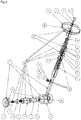
- An exemplary embodiment of the operation hammer 1 shows the figure Fig.2 in an exploded view.
- the hammer head 2 comprises a hammer head jacket a which surrounds the other components of the hammer head.
- a first magnet d Within the hammerhead jacket a are a first magnet d, springs c, a charging coil e, a second magnet i and an acceleration sensor h.
- the first magnet d is disposed inside a plastic tube i, this plastic tube i in turn is in a charging coil e and is tubular.
- the first magnet d is arranged so that it can move parallel to the coil e.
- a current is induced which can be used to supply energy to the acceleration sensor h. Therefore, the first magnet d with the springs c, the coil e and the plastic tube i serve as the energy supply means 50.
- the hammer head 2 comprises a closure j. This serves to be able to use components in the hammer head 2.
- the hammer handle 2 comprises the dispensing means 40.
- the dispensing means 40 in turn comprises in this embodiment here a green LED k a yellow LED m and a red LED I.
- the hammer handle 3 has a board r with an AV converter n, a microprocessor o, a data logger p and capacitor q.
- the AV converter n, microprocessor o and datalogger p serve as the evaluation unit 30.
- the AV converter n is used to convert the analog data of the acceleration sensor h into digital data.
- the microprocessor o is used to process the digital data.
- the data logger p is used for temporary storage of the data.
- the capacitors q serve here as energy supply means 50 for the evaluation means 30 and the output means 40.
- the hammer handle 3 comprises a charge coil f. This is designed so that it can absorb energy through induction and charge the capacitors q.
- the hammer handle 3 comprises a closure g. This serves to be able to use components in the hammer handle 3.
- the hammer handle 3 comprises a handle b.
- This handle has a corrugated surface so that the operation hammer 1 can be better grasped.
- the charging station 60 comprises a charging station housing s for receiving the further components of the charging station 60.
- the charging station housing s is designed so that the hammer handle 3 can be set in the charging station.
- the charging station comprises a coil t with an iron core v.
- the coil t is arranged so that it can be connected to an external AC power source and can supply the capacitors q in the hammer handle 3 with energy via the charging coil f.
- the iron core v is movably disposed within the coil.
- the loading can also be done by simply shaking the operation hammer 1 with the charging station 60.
- the coil t with iron core v can serve as energy supply means 50.
- the charging station 60 is here designed so that it can receive data of the data logger p.
- the charging station can also serve as part of the evaluation means 30.
- the charging station 60 includes a closure u. This serves to be able to use components in the charging station housing s.
- each of these embodiments may comprise at least one sterilizable plastic panel, an input means 20 and / or a charging station 60.
Landscapes
- Health & Medical Sciences (AREA)
- Life Sciences & Earth Sciences (AREA)
- Orthopedic Medicine & Surgery (AREA)
- Surgery (AREA)
- Biomedical Technology (AREA)
- Engineering & Computer Science (AREA)
- Nuclear Medicine, Radiotherapy & Molecular Imaging (AREA)
- Heart & Thoracic Surgery (AREA)
- Medical Informatics (AREA)
- Molecular Biology (AREA)
- Animal Behavior & Ethology (AREA)
- General Health & Medical Sciences (AREA)
- Public Health (AREA)
- Veterinary Medicine (AREA)
- Measuring And Recording Apparatus For Diagnosis (AREA)
Priority Applications (1)
| Application Number | Priority Date | Filing Date | Title |
|---|---|---|---|
| EP18155665.5A EP3524197A1 (fr) | 2018-02-08 | 2018-02-08 | Marteau chirurgical |
Applications Claiming Priority (1)
| Application Number | Priority Date | Filing Date | Title |
|---|---|---|---|
| EP18155665.5A EP3524197A1 (fr) | 2018-02-08 | 2018-02-08 | Marteau chirurgical |
Publications (1)
| Publication Number | Publication Date |
|---|---|
| EP3524197A1 true EP3524197A1 (fr) | 2019-08-14 |
Family
ID=61223710
Family Applications (1)
| Application Number | Title | Priority Date | Filing Date |
|---|---|---|---|
| EP18155665.5A Withdrawn EP3524197A1 (fr) | 2018-02-08 | 2018-02-08 | Marteau chirurgical |
Country Status (1)
| Country | Link |
|---|---|
| EP (1) | EP3524197A1 (fr) |
Cited By (2)
| Publication number | Priority date | Publication date | Assignee | Title |
|---|---|---|---|---|
| CN112255090A (zh) * | 2020-11-13 | 2021-01-22 | 深圳信息职业技术学院 | 一种可变锤面数字敲击锤及用于复合材料检测方法 |
| EP4173598A1 (fr) * | 2021-10-26 | 2023-05-03 | Justus-Liebig-Universität Gießen | Surveillance des coups de marteau |
Citations (5)
| Publication number | Priority date | Publication date | Assignee | Title |
|---|---|---|---|---|
| EP0141013A1 (fr) | 1983-10-26 | 1985-05-15 | Pcb Piezotronics, Inc. | Marteau d'essai muni d'un système de mesure |
| DE19906140A1 (de) | 1998-12-04 | 2000-07-06 | Manfred Zimmermann | Vorrichtung zur Bestimmung und Dokumentation von motorischen Reflexen, insbesondere von Muskelreflexen und/oder Sehnenreflexen |
| CN201939382U (zh) * | 2011-02-10 | 2011-08-24 | 曹立杰 | 一种新型的扣诊锤 |
| WO2012022007A2 (fr) * | 2010-08-16 | 2012-02-23 | Gerardo Andres Rivas Perlwitz | Marteau médical pour réflexes qui comprend des capteurs et transmission de données |
| US20150282856A1 (en) * | 2014-04-02 | 2015-10-08 | Centre National De La Recherche Scientifique (Cnrs) | Device for assisting with the placement of an orthopedic instrument |
-
2018
- 2018-02-08 EP EP18155665.5A patent/EP3524197A1/fr not_active Withdrawn
Patent Citations (5)
| Publication number | Priority date | Publication date | Assignee | Title |
|---|---|---|---|---|
| EP0141013A1 (fr) | 1983-10-26 | 1985-05-15 | Pcb Piezotronics, Inc. | Marteau d'essai muni d'un système de mesure |
| DE19906140A1 (de) | 1998-12-04 | 2000-07-06 | Manfred Zimmermann | Vorrichtung zur Bestimmung und Dokumentation von motorischen Reflexen, insbesondere von Muskelreflexen und/oder Sehnenreflexen |
| WO2012022007A2 (fr) * | 2010-08-16 | 2012-02-23 | Gerardo Andres Rivas Perlwitz | Marteau médical pour réflexes qui comprend des capteurs et transmission de données |
| CN201939382U (zh) * | 2011-02-10 | 2011-08-24 | 曹立杰 | 一种新型的扣诊锤 |
| US20150282856A1 (en) * | 2014-04-02 | 2015-10-08 | Centre National De La Recherche Scientifique (Cnrs) | Device for assisting with the placement of an orthopedic instrument |
Cited By (2)
| Publication number | Priority date | Publication date | Assignee | Title |
|---|---|---|---|---|
| CN112255090A (zh) * | 2020-11-13 | 2021-01-22 | 深圳信息职业技术学院 | 一种可变锤面数字敲击锤及用于复合材料检测方法 |
| EP4173598A1 (fr) * | 2021-10-26 | 2023-05-03 | Justus-Liebig-Universität Gießen | Surveillance des coups de marteau |
Similar Documents
| Publication | Publication Date | Title |
|---|---|---|
| DE60023036T2 (de) | Vorrichtung zum in-vivo-messen von druck und druckschwankugen im oder am knochen | |
| DE102006032127B4 (de) | Kalibrierverfahren und Kalibriervorrichtung für eine chirurgische Referenzierungseinheit | |
| DE102011113126A1 (de) | Leistungseinheit, medizinisches Handgerät und Einrichtung | |
| US5233982A (en) | Method and apparatus for defining a parameter during the output of an electrical pulse to biological tissue | |
| DE10014542A1 (de) | Erfassungssystem und Erfassungsverfahren für chirurgische Instrumente und Materialien | |
| WO2003095936A1 (fr) | Outil d'assemblage pour implant modulaire | |
| EP3273900A1 (fr) | Bras de retenue à usage médical équipé d'un dispositif de commande amovible, et dispositif de commande de celui-ci | |
| EP3524197A1 (fr) | Marteau chirurgical | |
| EP3341077A2 (fr) | Système de transmission sans fil d'énergie et/ou de signaux, de conversion de l'énergie et/ou des signaux en autres formes d'énergie et/ou autres formes de signaux et application et détection dans des zone périphériques du système | |
| DE3714966A1 (de) | Vorrichtung zum messen der kraftschluessigen verbindung einer zementfrei implantierbaren schaftprothese mit einem knochenschaft | |
| DE102008005180A1 (de) | Vorrichtung mit einem Prothesenteil und einem Sensor zum in-vivo-Überprüfen der Lockerung des Prothesenteils | |
| EP1329192B1 (fr) | Dispositif de rayons X | |
| EP2338562A1 (fr) | Vibrateur MRT Lorentz | |
| DE102014109683B4 (de) | Vorrichtung zur Detektion einer Lockerung und/oder Abnutzung einer Endoprothese | |
| DE102013109180B3 (de) | Vorrichtung und Verfahren zur Erfassung von kiefergelenkgeführten Unterkieferbewegungen, Artikulator und Verfahren zum Simulieren einer Kieferbewegung an einem Artikulator | |
| DE102006030343B4 (de) | Vorrichtung zur Implantation einer Prothese in einen Knochen | |
| WO2021037631A1 (fr) | Système de mesure pour mesurer une réactivité main-œil | |
| EP3307159B1 (fr) | Procédé et dispositif de détermination d'un mouvement volontaire d'un membre | |
| DE202006010728U1 (de) | Kalibriervorrichtung für eine chirurgische Referenzierungseinheit | |
| EP3937157B1 (fr) | Procédé de production reproductible de fractures osseuses définies | |
| DE102019122374B4 (de) | Verfahren zum Herstellen eines Prothesenschaftes | |
| AT506364B1 (de) | Verformungen an knochen-implantat-anordnungen | |
| DE102012015091A1 (de) | Leistungseinheit, medizinisches Handgerät und Einrichtung | |
| EP3672484A1 (fr) | Dispositif et procédé de détection, d'évaluation et de différenciation entre des tremblements de repos et une bradykinésie | |
| DE102010021498B4 (de) | System zur Steifigkeitsmessung eines Objektes sowie Verfahren |
Legal Events
| Date | Code | Title | Description |
|---|---|---|---|
| PUAI | Public reference made under article 153(3) epc to a published international application that has entered the european phase |
Free format text: ORIGINAL CODE: 0009012 |
|
| AK | Designated contracting states |
Kind code of ref document: A1 Designated state(s): AL AT BE BG CH CY CZ DE DK EE ES FI FR GB GR HR HU IE IS IT LI LT LU LV MC MK MT NL NO PL PT RO RS SE SI SK SM TR |
|
| AX | Request for extension of the european patent |
Extension state: BA ME |
|
| STAA | Information on the status of an ep patent application or granted ep patent |
Free format text: STATUS: THE APPLICATION IS DEEMED TO BE WITHDRAWN |
|
| 18D | Application deemed to be withdrawn |
Effective date: 20200215 |