EP3524031B1 - Procédé et appareil de prise en charge de mécanismes d'économie d'énergie pour nr dans un système de communication sans fil - Google Patents
Procédé et appareil de prise en charge de mécanismes d'économie d'énergie pour nr dans un système de communication sans fil Download PDFInfo
- Publication number
- EP3524031B1 EP3524031B1 EP17858717.6A EP17858717A EP3524031B1 EP 3524031 B1 EP3524031 B1 EP 3524031B1 EP 17858717 A EP17858717 A EP 17858717A EP 3524031 B1 EP3524031 B1 EP 3524031B1
- Authority
- EP
- European Patent Office
- Prior art keywords
- bandwidth
- control channel
- power saving
- saving state
- control
- Prior art date
- Legal status (The legal status is an assumption and is not a legal conclusion. Google has not performed a legal analysis and makes no representation as to the accuracy of the status listed.)
- Active
Links
- 238000000034 method Methods 0.000 title claims description 39
- 238000004891 communication Methods 0.000 title claims description 35
- 230000007246 mechanism Effects 0.000 title description 8
- 230000005540 biological transmission Effects 0.000 claims description 49
- 238000005259 measurement Methods 0.000 claims description 29
- 238000012544 monitoring process Methods 0.000 claims description 23
- 230000015654 memory Effects 0.000 claims description 11
- 230000006399 behavior Effects 0.000 description 12
- 238000001228 spectrum Methods 0.000 description 12
- 238000013459 approach Methods 0.000 description 9
- 238000005516 engineering process Methods 0.000 description 8
- 230000006978 adaptation Effects 0.000 description 6
- 238000001514 detection method Methods 0.000 description 6
- 230000008859 change Effects 0.000 description 5
- 230000004044 response Effects 0.000 description 5
- 230000011664 signaling Effects 0.000 description 5
- 230000006870 function Effects 0.000 description 4
- 238000013507 mapping Methods 0.000 description 4
- 238000012545 processing Methods 0.000 description 4
- 230000001960 triggered effect Effects 0.000 description 4
- 238000010586 diagram Methods 0.000 description 3
- 230000008569 process Effects 0.000 description 3
- 230000003139 buffering effect Effects 0.000 description 2
- 239000000969 carrier Substances 0.000 description 2
- 230000007774 longterm Effects 0.000 description 2
- 101000741965 Homo sapiens Inactive tyrosine-protein kinase PRAG1 Proteins 0.000 description 1
- 102100038659 Inactive tyrosine-protein kinase PRAG1 Human genes 0.000 description 1
- 230000002776 aggregation Effects 0.000 description 1
- 238000004220 aggregation Methods 0.000 description 1
- 230000001413 cellular effect Effects 0.000 description 1
- 125000004122 cyclic group Chemical group 0.000 description 1
- 238000013461 design Methods 0.000 description 1
- 230000000694 effects Effects 0.000 description 1
- 238000005265 energy consumption Methods 0.000 description 1
- 238000007726 management method Methods 0.000 description 1
- 230000000737 periodic effect Effects 0.000 description 1
- 238000013439 planning Methods 0.000 description 1
- 230000009467 reduction Effects 0.000 description 1
- 238000012827 research and development Methods 0.000 description 1
- 238000013468 resource allocation Methods 0.000 description 1
- 230000007704 transition Effects 0.000 description 1
- 239000002699 waste material Substances 0.000 description 1
Images


Classifications
-
- H—ELECTRICITY
- H04—ELECTRIC COMMUNICATION TECHNIQUE
- H04W—WIRELESS COMMUNICATION NETWORKS
- H04W52/00—Power management, e.g. TPC [Transmission Power Control], power saving or power classes
- H04W52/02—Power saving arrangements
- H04W52/0209—Power saving arrangements in terminal devices
-
- H—ELECTRICITY
- H04—ELECTRIC COMMUNICATION TECHNIQUE
- H04W—WIRELESS COMMUNICATION NETWORKS
- H04W52/00—Power management, e.g. TPC [Transmission Power Control], power saving or power classes
- H04W52/02—Power saving arrangements
- H04W52/0209—Power saving arrangements in terminal devices
- H04W52/0212—Power saving arrangements in terminal devices managed by the network, e.g. network or access point is master and terminal is slave
- H04W52/0216—Power saving arrangements in terminal devices managed by the network, e.g. network or access point is master and terminal is slave using a pre-established activity schedule, e.g. traffic indication frame
-
- H—ELECTRICITY
- H04—ELECTRIC COMMUNICATION TECHNIQUE
- H04W—WIRELESS COMMUNICATION NETWORKS
- H04W72/00—Local resource management
- H04W72/04—Wireless resource allocation
- H04W72/044—Wireless resource allocation based on the type of the allocated resource
- H04W72/0453—Resources in frequency domain, e.g. a carrier in FDMA
-
- H—ELECTRICITY
- H04—ELECTRIC COMMUNICATION TECHNIQUE
- H04L—TRANSMISSION OF DIGITAL INFORMATION, e.g. TELEGRAPHIC COMMUNICATION
- H04L41/00—Arrangements for maintenance, administration or management of data switching networks, e.g. of packet switching networks
- H04L41/08—Configuration management of networks or network elements
- H04L41/0803—Configuration setting
- H04L41/0806—Configuration setting for initial configuration or provisioning, e.g. plug-and-play
-
- H—ELECTRICITY
- H04—ELECTRIC COMMUNICATION TECHNIQUE
- H04L—TRANSMISSION OF DIGITAL INFORMATION, e.g. TELEGRAPHIC COMMUNICATION
- H04L41/00—Arrangements for maintenance, administration or management of data switching networks, e.g. of packet switching networks
- H04L41/08—Configuration management of networks or network elements
- H04L41/0803—Configuration setting
- H04L41/0813—Configuration setting characterised by the conditions triggering a change of settings
- H04L41/0816—Configuration setting characterised by the conditions triggering a change of settings the condition being an adaptation, e.g. in response to network events
-
- H—ELECTRICITY
- H04—ELECTRIC COMMUNICATION TECHNIQUE
- H04L—TRANSMISSION OF DIGITAL INFORMATION, e.g. TELEGRAPHIC COMMUNICATION
- H04L43/00—Arrangements for monitoring or testing data switching networks
- H04L43/04—Processing captured monitoring data, e.g. for logfile generation
- H04L43/045—Processing captured monitoring data, e.g. for logfile generation for graphical visualisation of monitoring data
-
- H—ELECTRICITY
- H04—ELECTRIC COMMUNICATION TECHNIQUE
- H04L—TRANSMISSION OF DIGITAL INFORMATION, e.g. TELEGRAPHIC COMMUNICATION
- H04L43/00—Arrangements for monitoring or testing data switching networks
- H04L43/10—Active monitoring, e.g. heartbeat, ping or trace-route
- H04L43/103—Active monitoring, e.g. heartbeat, ping or trace-route with adaptive polling, i.e. dynamically adapting the polling rate
-
- H—ELECTRICITY
- H04—ELECTRIC COMMUNICATION TECHNIQUE
- H04W—WIRELESS COMMUNICATION NETWORKS
- H04W24/00—Supervisory, monitoring or testing arrangements
- H04W24/08—Testing, supervising or monitoring using real traffic
-
- H—ELECTRICITY
- H04—ELECTRIC COMMUNICATION TECHNIQUE
- H04W—WIRELESS COMMUNICATION NETWORKS
- H04W52/00—Power management, e.g. TPC [Transmission Power Control], power saving or power classes
- H04W52/02—Power saving arrangements
- H04W52/0209—Power saving arrangements in terminal devices
- H04W52/0225—Power saving arrangements in terminal devices using monitoring of external events, e.g. the presence of a signal
- H04W52/0229—Power saving arrangements in terminal devices using monitoring of external events, e.g. the presence of a signal where the received signal is a wanted signal
-
- Y—GENERAL TAGGING OF NEW TECHNOLOGICAL DEVELOPMENTS; GENERAL TAGGING OF CROSS-SECTIONAL TECHNOLOGIES SPANNING OVER SEVERAL SECTIONS OF THE IPC; TECHNICAL SUBJECTS COVERED BY FORMER USPC CROSS-REFERENCE ART COLLECTIONS [XRACs] AND DIGESTS
- Y02—TECHNOLOGIES OR APPLICATIONS FOR MITIGATION OR ADAPTATION AGAINST CLIMATE CHANGE
- Y02D—CLIMATE CHANGE MITIGATION TECHNOLOGIES IN INFORMATION AND COMMUNICATION TECHNOLOGIES [ICT], I.E. INFORMATION AND COMMUNICATION TECHNOLOGIES AIMING AT THE REDUCTION OF THEIR OWN ENERGY USE
- Y02D30/00—Reducing energy consumption in communication networks
- Y02D30/70—Reducing energy consumption in communication networks in wireless communication networks
Definitions
- the present invention relates to wireless communications, and more particularly, to a method and apparatus for supporting energy saving mechanisms for a new radio access technology (NR) in a wireless communication system.
- NR new radio access technology
- 3rd generation partnership project (3GPP) long-term evolution (LTE) is a technology for enabling high-speed packet communications.
- 3GPP 3rd generation partnership project
- LTE long-term evolution
- Many schemes have been proposed for the LTE objective including those that aim to reduce user and provider costs, improve service quality, and expand and improve coverage and system capacity.
- the 3GPP LTE requires reduced cost per bit, increased service availability, flexible use of a frequency band, a simple structure, an open interface, and adequate power consumption of a terminal as an upper-level requirement.
- next generation communication As more and more communication devices require more communication capacity, there is a need for improved mobile broadband communication over existing radio access technology.
- massive machine type communications MTC
- MTC massive machine type communications
- communication system design considering reliability/latency sensitive service/UE is being discussed.
- URLLC ultra-reliable and low latency communication
- This new technology may be called new radio access technology (new RAT or NR) for convenience.
- analog beamforming may be introduced.
- mmW millimeter wave
- the wavelength is shortened so that a plurality of antennas can be installed in the same area.
- a total of 100 antenna elements can be installed in a 2-dimension array of 0.5 lambda (wavelength) intervals on a panel of 5 by 5 cm with a wavelength of 1 cm. Therefore, in mmW, multiple antenna elements can be used to increase the beamforming gain to increase the coverage or increase the throughput.
- TXRU transceiver unit
- independent beamforming is possible for each frequency resource.
- installing a TXRU on all 100 antenna elements has a problem in terms of cost effectiveness. Therefore, a method of mapping a plurality of antenna elements to one TXRU and adjusting the direction of a beam using an analog phase shifter is considered.
- This analog beamforming method has a disadvantage that it cannot perform frequency selective beaming because it can make only one beam direction in all bands.
- a hybrid beamforming with B TXRUs which is an intermediate form of digital beamforming and analog beamforming, and fewer than Q antenna elements, can be considered.
- B TXRUs which is an intermediate form of digital beamforming and analog beamforming, and fewer than Q antenna elements
- the direction of the beam that can be simultaneously transmitted is limited to B or less.
- US 2012/243638 A1 describes communication signals using a first and a second frequency band in a wireless network.
- the first frequency band may be associated with a first beamwidth while the second frequency band may be associated with a second beamwidth.
- An apparatus may include receiver circuitry arranged to receive first signals in a first frequency band associated with a first beamwidth and second signals in a second frequency band associated with a second beamwidth, the first signals comprising a frame synchronization parameter and the second signals comprising frame alignment signals.
- the apparatus may further include processor circuitry coupled to the receiver circuitry, the processor circuitry arranged to activate or deactivate the receiver circuitry to receive the frame alignment signals based on the frame synchronization parameter.
- US2016/127991 shows a User Equipment switching between first and second bandwidth when monitoring a control signal.
- the present invention provides a method and apparatus for supporting energy saving mechanisms for a new radio access technology (NR) in a wireless communication system.
- This present invention discusses mechanisms to support energy-efficient control/data channel processing mechanisms, as it appears in the attached claims.
- FIG. 1 shows a 3GPP LTE system.
- the 3rd generation partnership project (3GPP) long-term evolution (LTE) system 10 includes at least one eNodeB (eNB) 11.
- Respective eNBs 11 provide a communication service to particular geographical areas 15a, 15b, and 15c (which are generally called cells). Each cell may be divided into a plurality of areas (which are called sectors).
- a user equipment (UE) 12 may be fixed or mobile and may be referred to by other names such as mobile station (MS), mobile terminal (MT), user terminal (UT), subscriber station (SS), wireless device, personal digital assistant (PDA), wireless modem, handheld device.
- the eNB 11 generally refers to a fixed station that communicates with the UE 12 and may be called by other names such as base station (BS), base transceiver system (BTS), access point (AP), etc.
- BS base station
- BTS base transceiver system
- AP access point
- a UE belongs to one cell, and the cell to which a UE belongs is called a serving cell.
- An eNB providing a communication service to the serving cell is called a serving eNB.
- the wireless communication system is a cellular system, so a different cell adjacent to the serving cell exists.
- the different cell adjacent to the serving cell is called a neighbor cell.
- An eNB providing a communication service to the neighbor cell is called a neighbor eNB.
- the serving cell and the neighbor cell are relatively determined based on a UE.
- DL refers to communication from the eNB 11 to the UE 12
- UL refers to communication from the UE 12 to the eNB 11.
- a transmitter may be part of the eNB 11 and a receiver may be part of the UE 12.
- a transmitter may be part of the UE 12 and a receiver may be part of the eNB 11.
- the wireless communication system may be any one of a multiple-input multiple-output (MIMO) system, a multiple-input single-output (MISO) system, a single-input single-output (SISO) system, and a single-input multiple-output (SIMO) system.
- MIMO multiple-input multiple-output
- MISO multiple-input single-output
- SISO single-input single-output
- SIMO single-input multiple-output
- the MIMO system uses a plurality of transmission antennas and a plurality of reception antennas.
- the MISO system uses a plurality of transmission antennas and a single reception antenna.
- the SISO system uses a single transmission antenna and a single reception antenna.
- the SIMO system uses a single transmission antenna and a plurality of reception antennas.
- a transmission antenna refers to a physical or logical antenna used for transmitting a signal or a stream
- a reception antenna refers to a physical or logical antenna used
- FIG. 2 shows structure of a radio frame of 3GPP LTE.
- a radio frame includes 10 subframes.
- a subframe includes two slots in time domain.
- a time for transmitting one transport block by higher layer to physical layer is defined as a transmission time interval (TTI).
- TTI transmission time interval
- one subframe may have a length of 1ms, and one slot may have a length of 0.5ms.
- One slot includes a plurality of orthogonal frequency division multiplexing (OFDM) symbols in time domain. Since the 3GPP LTE uses the OFDMA in the DL, the OFDM symbol is for representing one symbol period.
- the OFDM symbols may be called by other names depending on a multiple-access scheme.
- a resource block is a resource allocation unit, and includes a plurality of contiguous subcarriers in one slot.
- the structure of the radio frame is shown for exemplary purposes only. Thus, the number of subframes included in the radio frame or the number of slots included in the subframe or the number of OFDM symbols included in the slot may be modified in various manners.
- the wireless communication system may be divided into a frequency division duplex (FDD) scheme and a time division duplex (TDD) scheme.
- FDD frequency division duplex
- TDD time division duplex
- UL transmission and DL transmission are made at different frequency bands.
- UL transmission and DL transmission are made during different periods of time at the same frequency band.
- a channel response of the TDD scheme is substantially reciprocal. This means that a DL channel response and a UL channel response are almost the same in a given frequency band.
- the TDD-based wireless communication system is advantageous in that the DL channel response can be obtained from the UL channel response.
- the entire frequency band is time-divided for UL and DL transmissions, so a DL transmission by the eNB and a UL transmission by the UE cannot be simultaneously performed.
- the UL transmission and the DL transmission are performed in different subframes.
- UL and DL transmission may be performed within a same subframe/slot in time division multiplexing (TDM)/frequency division multiplexing (FDM) manner.
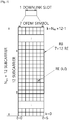
- FIG. 3 shows a resource grid for one downlink slot.
- a DL slot includes a plurality of OFDM symbols in time domain. It is described herein that one DL slot includes 7 OFDM symbols, and one RB includes 12 subcarriers in frequency domain as an example. However, the present invention is not limited thereto.
- Each element on the resource grid is referred to as a resource element (RE).
- One RB includes 12 ⁇ 7 or 12 ⁇ 14 resource elements.
- the number N DL of RBs included in the DL slot depends on a DL transmit bandwidth.
- the structure of a UL slot may be same as that of the DL slot.
- the number of OFDM symbols and the number of subcarriers may vary depending on the length of a CP, frequency spacing, etc.
- the number of OFDM symbols is 7 or 14, and in case of an extended CP, the number of OFDM symbols is 6 or 12.
- One of 128, 256, 512, 1024, 1536, 2048, 4096 and 8192 may be selectively used as the number of subcarriers in one OFDM symbol.
- 5th generation mobile networks or 5th generation wireless systems are the proposed next telecommunications standards beyond the current 4G LTE/international mobile telecommunications (IMT)-dvanced standards.
- 5G includes both new radio access technology (new RAT or NR) and LTE evolution.
- new RAT new RAT
- LTE evolution new radio access technology
- 5G planning aims at higher capacity than current 4G LTE, allowing a higher density of mobile broadband users, and supporting device-to-device, ultra-reliable, and massive machine communications.
- 5G research and development also aims at lower latency than 4G equipment and lower battery consumption, for better implementation of the Internet of things.
- different frame structure may be necessary for NR.
- different frame structure in which UL and DL may be present in every subframe or may change very frequently in the same carrier may be necessary for NR.
- Different application may require different minimum size of DL or UL portions to support different latency and coverage requirements.
- massive machine-type communication (mMTC) for high coverage case may require relatively long DL and UL portion so that one transmission can be successfully transmitted.
- mMTC massive machine-type communication
- different subcarrier spacing and/or different CP length may be considered. In this sense, it is necessary to consider mechanisms to allow different frame structures coexisting in the same carrier and be operated by the same cell/eNB
- the paired spectrum means that one carrier consists of two carriers.
- the one carrier may include a DL carrier and an UL carrier, which are paired with each other.
- communication such as DL, UL, device-to-device communication, and/or relay communication, may be performed by utilizing the paired spectrum.
- the unpaired spectrum means that that one carrier consists of only one carrier, like the current 4G LTE.
- communication such as DL, UL, device-to-device communication, and/or relay communication, may be performed in the unpaired spectrum.
- the following subframe types may be considered to support the paired spectrum and the unpaired spectrum mentioned above.
- subframe types listed above are only exemplary, and other subframe types may also be considered.
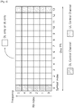
- FIG. 4 shows an example of subframe type for NR.
- the subframe shown in FIG. 4 may be used in TDD system of NR, in order to minimize latency of data transmission.
- the subframe contains 14 symbols in one TTI, like the current subframe.
- the subframe includes DL control channel in the first symbol, and UL control channel in the last symbol. The remaining symbols may be used for DL data transmission or for UL data transmission.
- DL transmission and UL transmission may sequentially proceed in one subframe.
- DL data may be transmitted in the subframe, and UL acknowledgement/non-acknowledgement (ACK/NACK) may also be received in the subframe.
- ACK/NACK UL acknowledgement/non-acknowledgement
- a time gap may be required for the transition process from the transmission mode to the reception mode or from the reception mode to the transmission mode.
- some OFDM symbols at the time of switching from DL to UL in the subframe structure may be set to the guard period (GP).
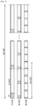
- FIG. 5 shows an example of symbol level alignment between different numerologies. Referring to FIG. 5 , the first 2 n symbols of F s have equal symbol length.
- FIG. 6 shows another example of symbol level alignment between different numerologies. Referring to FIG. 6-(a) , except for the first symbol of F s , all symbols of F s have equal symbol length. The length of first symbol of F s is sum of length of the second symbol and 0.51 us. Referring to FIG. 6-(b) , 0.51us is reserved, and all symbols have the equal length.
- FIG. 7 shows an example of slot/subframe level alignment between different numerologies.
- different numerologies are aligned at slot/subframe level, instead of symbol level alignment.
- TDM time division multiplexing
- FDM frequency division multiplexing
- the present invention mainly focuses power saving aspects, specifically for control channel and data channel monitoring procedures.
- the general procedure may be as follows.
- UL data transmission preparation may be started.
- the present invention proposes one of the following approaches.
- a UE may have a timer indicating during which the power saving state is activated, similar to DRX timer. Timer/period/duration of the power saving state may be configured by the network. Further, a power saving mode active state (“PSM_active”) may occur to check whether a UE needs to turn back to the active state. Specifically, the following states may be defined for the present invention.
- a UE may be configured with different set of numerologies used in the power saving state and active state. Further, a UE may be configured with different control resource sets used in the power saving state and active state. Alternatively, a UE may be configured with multiple control resource sets, and some resource set(s) among the multiple control resource sets may be deactivated in the power saving state. In other words, the monitoring resource set for control channel may be different in the power saving state and active state, either by implicit or explicit configuration. If implicit configuration is used, a UE may monitor search space candidates fallen into the minimum or default bandwidth configured for the power saving state (i.e. resource region or bandwidth used in the power saving state).
- FIG. 8 shows an example of a power saving state according to an embodiment of the present invention.
- the power saving state is operated as similar as the DRX operation.
- the UE monitors the UE RF bandwidth, which may be the maximum UE RF bandwidth or the configured UE RF bandwidth.
- the UE RF bandwidth is adapted to the narrower UE RF bandwidth compared to the UE RF bandwidth in the active state.
- the UE may take different approach in control/data channel monitoring as follows.
- cross-subframe/slot/TTI scheduling may be supported in order to allow sufficient time between control channel monitoring and data channel monitoring. If control channel is transmitted over the entire subframe/slot/TTI, cross-subframe/slot/TTI may have a gap between control subframe/slot/TTI and data subframe/slot/TTI. The gap may be configured by the network or fixed. The UE may report its capability on the required gap.
- the gap may be configured or fixed gap may be assumed between control channel and data channel.
- the UE may be configured whether a UE may use the gap in the power saving state or not by higher layer signaling. For the gap, at least one of the following options may be considered.
- the present invention also proposes that any power saving technique(s) is restricted only to the power saving state or efficient control channel monitoring state or activated, only when a UE is explicitly indicated with the behavior either by higher layer signaling or dynamic signaling. Also, a UE may implicitly activate the behavior if UE autonomous decision is allowed.
- a UE may miss detection of control channel, which may lead ambiguity between the UE and network.
- the network should allow possibility of control channel mis-detection, in terms of scheduling or determine any UE behavior.
- K may be configured as a range, e.g. [100 - 120], and a UE may initiate power saving state if reception of data-less control channel exceeds the range of values.
- a UE may send a feedback to the network whenever any behavior or mode change occurs. For example, an indication of mode change may be transmitted via physical random access channel (PRACH), scheduling request (SR), data channel or control channel.
- PRACH physical random access channel
- SR scheduling request
- the presence of data scheduling, or intention of data scheduling may be indicated dynamically indicate.
- the bandwidth of the control resource set may be fixed regardless of UE RF bandwidth.
- the UE may increase its RF bandwidth.
- the UE RF bandwidth is increased, it is expected that a UE may not reduce its RF bandwidth in the next slot for control channel monitoring.
- the UE may maintain larger bandwidth (than the bandwidth of the control resource set) over T slots/subframes. T may be configured by higher layer. If a UE receives data which spans beyond the bandwidth of the control resource set or minimum system bandwidth (or default PSM bandwidth), the UE may reset the timer. If a UE has not received which spans beyond the bandwidth of the control resource set or minimum system bandwidth (or default PSM bandwidth), the UE may reduce its bandwidth to default PSM bandwidth.
- the latency of control channel monitoring may be reduced, in order to quickly finish UE power on if data is not scheduled. If a UE needs to monitor search space candidates from 0 to M, a UE may assume that DL scheduling DCI is scheduled only between 0 to M/2, for example. By restricting search space candidates, the overall latency to finish control channel decoding can be minimized.
- different or double or increase subcarrier spacing for control channel transmission may be taken, and control transmission may occur over the same OFDM symbol counts or the same duration to the original duration, and then remained portion may be used for control channel decoding time.
- subcarrier spacing is 15 kHz, 30 or 60 kHz of subcarrier spacing may be used for the control channel transmission.
- the control is transmitted over 2 OFDM symbols, it may still be transmitted over 2 OFDM symbols of 15 kHz, 30 kHz and 60 kHz subcarrier spacing.
- bandwidth may be increased as well so that the required number of symbols can be kept as the same.
- the remained symbols (e.g. 2 for 30 kHz subcarrier spacing, 6 for 60 kHz subcarrier spacing) may be used for the gap for control channel decoding before data transmission.
- periodic or aperiodic cell common or group-common or UE-specific broadcast channel/signal indication which indicates whether the UE will be scheduled with data or not may be used. If a UE is indicated that there will be no data scheduled, the UE may only monitor control channel, or may take the behavior as mentioned above for the power saving state.
- the search space to carry the signal may be restricted for fast decoding latency. This indication may also include whether a UE is scheduled with cross-subframe/slot/TTI scheduling or same-subframe/slot/TTI scheduling.
- a UE When a UE is in the power saving state or is configured to monitor reduced bandwidth than UE RF bandwidth, it is necessary to handle RRM accordingly.
- a UE may be allowed to increase RF bandwidth per configured RRM bandwidth (i.e. same RRM as in the active state).
- a UE may be allowed to stay at the reduced RF bandwidth for the power saving state, which may lead different RRM measurement in the power saving state and active state.
- the frequency region in which RRM RS is transmitted may be different.
- a UE may be required to perform measurement based on measurement gap for RF retuning. This is particularly necessary when frequency region of the power saving state is not within UE RF bandwidth if UE tunes to different frequency or changes its RF bandwidth for RRM measurement. For example, it is assumed that the UE supports 100 MHz, system bandwidth is 500 MHz, RRM RS is transmitted in the center 100 MHz, and PSM default bandwidth is 20 MHz configured in edge of the system bandwidth. In this case, for RRM measurement, a UE needs measurement gap. Alternatively, to minimize the necessity of measurement gap, the default PSM bandwidth may always be aligned with configured RRM bandwidth for the UE in terms of center frequency and bandwidth.
- measurement gap may be configured in absolute time (e.g. 6ms) or based on subframe or based on the primary cell (PCell) numerology (e.g. 6 slots) or the smallest subcarrier spacing used in frequency bands where measurement may occur or higher layer configured with slots and the numerology.
- PCell primary cell
- numerology e.g. 6 slots
- RRM measurement if RRM behavior is different between the power saving state and active state or between different UE RF bandwidths, different RRM measurement resources in terms of time/frequency resource may be configured. For example, different RRM bandwidth and time location in which measurement may occur may be configured differently between the power saving state and active state. Also, if a UE performs measurement on the default PSM bandwidth, it is necessary to consider neighbor cell measurement as well. Thus, a UE may expect synchronization signals from serving cell and neighbor cell on the configured measurement bandwidth. To avoid confusion between main synchronization signals on the anchor subband from additional synchronization signals, different root sequence, location and/or other information may be used. A UE may perform different cell search in case of measurement in different bandwidth.
- a UE is expected to perform RLF monitoring in both the power saving state and active state.
- a UE behavior may be as follows (but not limited thereto).
- the latency may be needed for bandwidth adaptation. At least when dynamic bandwidth adaptation is used, the maximum latency needs to be assumed regardless of actual necessary adjustment latency.
- the maximum latency may be configured by higher layer, and possibly, the required latency may be signaled by the UE to the network.
- RBG When different bandwidth is configured, in order to align and support efficient multiplexing of data between different UE bandwidths for different UEs, it may be necessary to align RBGs among different UE RF bandwidths.
- RBG is constructed based on only system bandwidth and each adapted UE RF bandwidth may follow RBG constructed based on system bandwidth. If different RBGs are used based on UE RF bandwidth, it may be necessary to restrict UE RF bandwidth as a multiple of RBGs based on system bandwidth.
- distributed mapping may be restricted to the configured UE RF bandwidth or minimum system bandwidth (e.g. for common data scheduling). Alternatively, bandwidth in which distributed mapping is applied may also be configured by higher layer.
- the minimum bandwidth or default PSM bandwidth may be configured larger than the initial or minimum system bandwidth in which common data is scheduled.
- some configured common control/data scheduling timing may also be used, and a UE may increase its RF bandwidth to receive common control/data.
- bandwidth adaptation When dynamic bandwidth adaptation is used, similar mechanism used in DL may also be used in UL. However, the gap for bandwidth adaptation may be necessary between DL to UL switching gap and UL portion. It may also need to be clarified whether physical uplink shared channel (PUSCH) and physical uplink control channel (PUCCH) or PUSCH and uplink control information (UCI) transmission can be done in different bandwidth, which may require bandwidth adaptation with frequency retuning. If this is supported, necessary gap between PUSCH and PUCCH may also be necessary. In case of TDD, it is generally desirable to keep the same center between DL and UL, thus, bandwidth adaptation between DL and UL may be done with keeping the same center frequency.
- PUSCH physical uplink shared channel
- PUCCH physical uplink control channel
- UCI uplink control information
- the same bandwidth may be used between DL and UL unless it is separately/independently configured.
- the resource location of UCI may also be different depending on the configured UL bandwidth for UCI transmission or UL transmission in general. For example, if PUCCH resource is configured at the edge of system bandwidth or configured UE bandwidth, the same or separate offset to indicate PUCCH resource from the edge of system bandwidth or configured UE bandwidth may be configured. In other words, base resource for PUCCH or UCI transmission may be different between different UE RF bandwidths. At least in case of paired spectrum, different bandwidth may be used between DL and UL. For example, in UL heavy case, UL bandwidth may be configured as larger compared to DL bandwidth. In other words, the power saving state may be configured per DL and UL, independently.
- tracking RS may be transmitted periodically within a certain system bandwidth.
- UE bandwidth is adapted, the following options may be considered.
- a UE may perform tracking only in the configured BWP (or active BWP).
- FIG. 9 shows a method for operating in a power saving state by a UE according to an embodiment of the present invention.
- the present invention described above may be applied to this embodiment.
- step S100 the UE enters an active state.
- step S110 the UE monitors a first RF bandwidth for the active state.
- step S120 the UE enters the power saving state.
- step S130 the UE monitors a second RF bandwidth, which is restricted to M MHz within the first RF bandwidth, for the power saving state.
- the first RF bandwidth may correspond to a maximum UE RF bandwidth, or correspond to M1 MHz, which is configured by a network and broader than the second RF bandwidth.
- the second RF bandwidth may correspond to a default minimum bandwidth configured by a network, or correspond an initial system subband.
- a frequency location of the second RF bandwidth may be configured by a network.
- a timer during which the power saving state is activated may be configured by the network.
- the UE may enter the power saving state autonomously if the UE is configured with DRX.
- the UE enters the power saving state autonomously if the UE detects that the UE has monitored a control channel where no data has been scheduled at least K times.
- Different sets of numerologies may be used for the active state and the power saving state, respectively.
- Different sets of control channel resource may be used for the active state and the power saving state, respectively.
- a bandwidth of a control resource set may be fixed regardless of UE RF bandwidth.
- a RRM measurement may be performed on the first RF bandwidth, while the UE is in the power saving state.
- a RBG may be configured based on a system bandwidth, and the first RF bandwidth and the second RF bandwidth may follow the RBG.
- the second RF bandwidth may be used both for DL and UL, respectively.
- a resource location of a PUCCH may be configured depending on the second RF bandwidth for PUCCH transmission.
- FIG. 10 shows a wireless communication system to implement an embodiment of the present invention.
- a network node 800 includes a processor 810, a memory 820 and a transceiver 830.
- the processor 810 may be configured to implement proposed functions, procedures and/or methods described in this description. Layers of the radio interface protocol may be implemented in the processor 810.
- the memory 820 is operatively coupled with the processor 810 and stores a variety of information to operate the processor 810.
- the transceiver 830 is operatively coupled with the processor 810, and transmits and/or receives a radio signal.
- a UE 900 includes a processor 910, a memory 920 and a transceiver 930.
- the processor 910 may be configured to implement proposed functions, procedures and/or methods described in this description. Layers of the radio interface protocol may be implemented in the processor 910.
- the memory 920 is operatively coupled with the processor 910 and stores a variety of information to operate the processor 910.
- the transceiver 930 is operatively coupled with the processor 910, and transmits and/or receives a radio signal.
- the processors 810, 910 may include application-specific integrated circuit (ASIC), other chipset, logic circuit and/or data processing device.
- the memories 820, 920 may include read-only memory (ROM), random access memory (RAM), flash memory, memory card, storage medium and/or other storage device.
- the transceivers 830, 930 may include baseband circuitry to process radio frequency signals.
- the techniques described herein can be implemented with modules (e.g., procedures, functions, and so on) that perform the functions described herein.
- the modules can be stored in memories 820, 920 and executed by processors 810, 910.
- the memories 820, 920 can be implemented within the processors 810, 910 or external to the processors 810, 910 in which case those can be communicatively coupled to the processors 810, 910 via various means as is known in the art.
Landscapes
- Engineering & Computer Science (AREA)
- Computer Networks & Wireless Communication (AREA)
- Signal Processing (AREA)
- Mobile Radio Communication Systems (AREA)
Claims (13)
- Procédé exécuté par un dispositif sans fil dans un système de communication sans fil, le procédé comprenant les étapes suivantes :configurer une première largeur de bande radiofréquence, RF, comme largeur de bande de surveillance, où la première largeur de bande RF est M1 MHz et est configurée dans un état actif ;surveiller (S110) un canal de commande sur la première largeur de bande RF ;commuter la largeur de bande de surveillance vers une seconde largeur de bande RF sur la base de la non-détection du canal de commande sur la première largeur de bande RF pendant une certaine durée, où la seconde largeur de bande RF est configurée dans un état d'économie d'énergie ; etsurveiller (S130) le canal de commande sur la seconde largeur de bande RF,où la seconde largeur de bande RF est une sous-bande par défaut qui est limitée à M MHz, et où M < M1.
- Procédé selon la revendication 1, dans lequel la première largeur de bande RF est configurée par un réseau.
- Procédé selon la revendication 1, dans lequel la première largeur de bande RF est plus large que la seconde largeur de bande RF.
- Procédé selon la revendication 1, dans lequel la seconde largeur de bande RF est configurée par un réseau.
- Procédé selon la revendication 1, dans lequel la seconde largeur de bande RF est une sous-bande initiale du système.
- Procédé selon la revendication 1, dans lequel un emplacement des fréquences de la seconde largeur de bande RF est configuré par un réseau.
- Procédé selon la revendication 1, dans lequel au moins l'un d'un signal de commande ou de données de commande est programmé sur la première largeur de bande RF.
- Procédé selon la revendication 1, dans lequel une largeur de bande d'un ensemble de ressources de commande est fixée indépendamment de la largeur de bande RF de l'équipement utilisateur, UE.
- Procédé selon la revendication 1, dans lequel une mesure de gestion des ressources radio, RRM, est effectuée sur la première largeur de bande RF.
- Procédé selon la revendication 1, dans lequel un groupe de blocs de ressources, RBG, est configuré sur la base d'une largeur de bande système ou de blocs de ressources physiques, PRB, communs parmi les dispositifs sans fil, et
dans lequel la première bande passante RF et la seconde bande passante RF suivent le RBG. - Procédé selon la revendication 1, dans lequel la seconde largeur de bande RF est utilisée à la fois pour la liaison descendante, DL, et la liaison montante, UL, respectivement.
- Procédé selon la revendication 1, dans lequel un emplacement de ressources d'un canal de commande de liaison montante physique, PUCCH, est configuré en fonction de la seconde largeur de bande RF pour la transmission PUCCH.
- Dispositif sans fil (900) dans un système de communication sans fil, comprenant :une mémoire (920) ;un émetteur-récepteur (930) ; etun processeur (910), couplé à la mémoire et à l'émetteur-récepteur, et configuré pour :configurer une première largeur de bande radiofréquence, RF, comme largeur de bande de surveillance, où la première largeur de bande RF est M1 MHz et est configurée dans un état actif ;commander l'émetteur-récepteur (930) pour surveiller un canal de commande sur la première largeur de bande RF ;commuter la largeur de bande de surveillance vers une seconde largeur de bande RF sur la base de la non-détection du canal de commande sur la première largeur de bande RF pendant une certaine durée, où la seconde largeur de bande RF est configurée dans un état d'économie d'énergie ; etcommander l'émetteur-récepteur (930) pour surveiller le canal de commande sur la seconde largeur de bande RF,où la seconde largeur de bande RF est une sous-bande par défaut qui est limitée à M MHz, et où M < M1.
Applications Claiming Priority (3)
| Application Number | Priority Date | Filing Date | Title |
|---|---|---|---|
| US201662405244P | 2016-10-07 | 2016-10-07 | |
| US201762442392P | 2017-01-04 | 2017-01-04 | |
| PCT/KR2017/010948 WO2018066923A1 (fr) | 2016-10-07 | 2017-09-29 | Procédé et appareil de prise en charge de mécanismes d'économie d'énergie pour nr dans un système de communication sans fil |
Publications (3)
| Publication Number | Publication Date |
|---|---|
| EP3524031A1 EP3524031A1 (fr) | 2019-08-14 |
| EP3524031A4 EP3524031A4 (fr) | 2019-08-14 |
| EP3524031B1 true EP3524031B1 (fr) | 2021-11-24 |
Family
ID=61831097
Family Applications (1)
| Application Number | Title | Priority Date | Filing Date |
|---|---|---|---|
| EP17858717.6A Active EP3524031B1 (fr) | 2016-10-07 | 2017-09-29 | Procédé et appareil de prise en charge de mécanismes d'économie d'énergie pour nr dans un système de communication sans fil |
Country Status (6)
| Country | Link |
|---|---|
| US (1) | US10904830B2 (fr) |
| EP (1) | EP3524031B1 (fr) |
| JP (1) | JP6786715B2 (fr) |
| KR (1) | KR102160241B1 (fr) |
| CN (1) | CN109792691B (fr) |
| WO (1) | WO2018066923A1 (fr) |
Families Citing this family (24)
| Publication number | Priority date | Publication date | Assignee | Title |
|---|---|---|---|---|
| CN117134867A (zh) * | 2016-11-02 | 2023-11-28 | 交互数字专利控股公司 | 接收机带宽适配 |
| CN108738145B (zh) * | 2017-04-24 | 2021-05-25 | 中国移动通信有限公司研究院 | 一种上行传输的调度方法、终端、基站及电子设备 |
| CN109152023B (zh) * | 2017-06-16 | 2021-02-12 | 华为技术有限公司 | 资源分配的方法、网络设备和终端设备 |
| CN111108796B (zh) * | 2017-09-28 | 2024-04-05 | 三星电子株式会社 | 用于在多个带宽部分上执行数据发射和测量的方法和网络节点 |
| US10887073B2 (en) | 2017-10-26 | 2021-01-05 | Ofinno, Llc | Activation and deactivation of bandwidth part |
| US10693620B2 (en) | 2017-10-27 | 2020-06-23 | Ofinno, Llc | Bandwidth part configuration and operation |
| US10750562B2 (en) | 2018-02-02 | 2020-08-18 | Ofinno, Llc | Connection failure report considering bandwidth |
| WO2019213870A1 (fr) * | 2018-05-09 | 2019-11-14 | Nokia Shanghai Bell Co., Ltd. | Conception d'informations de commande de liaison descendante à un seul étage permettant la planification de parties de bande passante à activités multiples |
| CA3099848A1 (fr) * | 2018-05-10 | 2019-11-14 | Ntt Docomo, Inc. | Terminal utilisateur |
| CN110602769B (zh) * | 2018-06-13 | 2021-04-13 | 维沃移动通信有限公司 | 数据处理方法、用户设备和网络侧设备 |
| CN110611938B (zh) * | 2018-06-15 | 2023-05-16 | 华为技术有限公司 | 通信方法和装置 |
| CN110690940A (zh) | 2018-07-04 | 2020-01-14 | 北京三星通信技术研究有限公司 | 下行接收方法、用于pdcch检测的方法、ue和计算机可读介质 |
| RU2767189C1 (ru) * | 2018-07-26 | 2022-03-16 | Гуандун Оппо Мобайл Телекоммьюникейшнс Корп., Лтд. | Способ передачи сигнала, сетевое устройство и терминальное устройство |
| CN110536380A (zh) * | 2018-08-10 | 2019-12-03 | 中兴通讯股份有限公司 | 状态确定、指示方法、通信设备、系统及存储介质 |
| EP3840496A4 (fr) | 2018-08-16 | 2021-09-01 | Beijing Xiaomi Mobile Software Co., Ltd. | Procédé de réglage de partie de bande passante et appareil de réglage de partie de bande passante |
| CN110856235A (zh) * | 2018-08-20 | 2020-02-28 | 华为技术有限公司 | 信息发送、接收方法与通信设备 |
| US11405943B2 (en) * | 2018-09-28 | 2022-08-02 | Apple Inc. | Cross-slot scheduling for New Radio |
| US11889473B2 (en) | 2018-10-19 | 2024-01-30 | Beijing Xiaomi Mobile Software Co., Ltd. | Resource switching method, and resource allocation method, apparatus, device and system |
| CN111107612B (zh) * | 2018-10-26 | 2021-10-15 | 华为技术有限公司 | 一种带宽部分的配置方法及装置 |
| CN111182592B (zh) * | 2018-12-28 | 2021-09-14 | 维沃移动通信有限公司 | 接收模式切换的方法及终端 |
| CN111436103B (zh) * | 2019-02-02 | 2021-12-24 | 维沃移动通信有限公司 | 节能模式的切换方法、节能模式的配置方法及通信设备 |
| US11510215B2 (en) * | 2019-03-28 | 2022-11-22 | Mediatek Inc. | Electronic device and method for radio resource management (RRM) measurement relaxation |
| WO2021062821A1 (fr) * | 2019-09-30 | 2021-04-08 | 华为技术有限公司 | Procédé et appareil de traitement d'informations et procédé et appareil d'indication d'informations |
| WO2023130460A1 (fr) * | 2022-01-10 | 2023-07-13 | Apple Inc. | Systèmes, procédés et dispositifs pour une économie d'énergie améliorée par l'intermédiaire d'une signalisation de référence dynamique |
Family Cites Families (29)
| Publication number | Priority date | Publication date | Assignee | Title |
|---|---|---|---|---|
| US6480709B2 (en) | 2001-01-19 | 2002-11-12 | Motorola, Inc. | Method for reducing scan time in a radio receiver |
| KR20030062524A (ko) | 2002-01-17 | 2003-07-28 | 삼성전자주식회사 | 슬롯모드 이동통신 단말기의 전력소모 감소방법 및 장치 |
| KR100547734B1 (ko) | 2003-06-13 | 2006-01-31 | 삼성전자주식회사 | 직교 주파수 분할 다중 방식을 사용하는 이동 통신시스템에서 매체 접속 제어 계층의 동작 상태 제어 방법 |
| US9084260B2 (en) * | 2005-10-26 | 2015-07-14 | Intel Corporation | Systems for communicating using multiple frequency bands in a wireless network |
| US8705375B2 (en) * | 2007-05-24 | 2014-04-22 | Nokia Corporation | Power save protocol interoperability detection |
| US8547853B2 (en) * | 2009-02-25 | 2013-10-01 | Texas Instruments Incorporated | Adaptive periodic power-save (PS) polling |
| CN103348759B (zh) * | 2011-02-09 | 2017-08-25 | 皇家飞利浦有限公司 | 在无线网络中使用辅助信道实现快速且高功效的关联的系统和方法 |
| US8934500B2 (en) * | 2011-04-13 | 2015-01-13 | Motorola Mobility Llc | Method and apparatus using two radio access technologies for scheduling resources in wireless communication systems |
| TWI432058B (zh) * | 2011-08-10 | 2014-03-21 | Acer Inc | 低耗能無線通訊方法 |
| EP2595425A1 (fr) | 2011-11-18 | 2013-05-22 | Panasonic Corporation | Indicateur de largeur de bande active pour équipements utilisateur à économie d'énergie |
| WO2013115573A1 (fr) * | 2012-02-01 | 2013-08-08 | Lg Electronics Inc. | Procédé et appareil de transmission d'informations de défaillance de liaison radio dans un système de communication sans fil |
| US9603151B2 (en) * | 2012-02-21 | 2017-03-21 | Telefonaktiebolaget Lm Ericsson (Publ) | Data transmission scheduling using energy consumption profile of terminal device |
| US9615401B2 (en) * | 2012-12-11 | 2017-04-04 | Qualcomm Incorporated | Methods and apparatus for updating a device configuration |
| US9066197B2 (en) * | 2013-01-22 | 2015-06-23 | Nokia Corporation | Method, apparatus, and computer program product for power save control for tethering connections |
| US10560887B2 (en) * | 2013-05-06 | 2020-02-11 | Qualcomm Incorporated | Routing modification based on handover detection |
| JP6456951B2 (ja) * | 2013-08-04 | 2019-01-23 | エルジー エレクトロニクス インコーポレイティド | チャネルアクセス方法及び装置 |
| WO2016016690A1 (fr) * | 2014-07-31 | 2016-02-04 | Pismo Labs Technology Limited | Systèmes et procédés permettant de changer la fréquence d'extraction de données de surveillance |
| US10516594B2 (en) * | 2014-12-21 | 2019-12-24 | Pismo Labs Technology Limited | Systems and methods for changing the frequency of monitoring data |
| US9374796B2 (en) | 2014-10-10 | 2016-06-21 | Qualcomm Incorporated | Channel structure for a cellular internet of things system |
| US9572106B2 (en) * | 2014-10-31 | 2017-02-14 | Qualcomm Incorporated | Dynamic bandwidth switching for reducing power consumption in wireless communication devices |
| KR102246464B1 (ko) * | 2015-08-13 | 2021-04-30 | 삼성전자 주식회사 | 무선 통신 시스템에서 전자장치의 전력 절감 방법 및 장치 |
| JP6567371B2 (ja) * | 2015-09-15 | 2019-08-28 | 株式会社東芝 | 無線通信装置 |
| WO2017052596A1 (fr) * | 2015-09-25 | 2017-03-30 | Maruti Gupta | Radio d'activation à faible consommation d'énergie pour des dispositifs mobiles |
| US20170195954A1 (en) * | 2016-01-05 | 2017-07-06 | Chittabrata Ghosh | Restrictive service period for power save devices |
| WO2017133792A1 (fr) * | 2016-02-05 | 2017-08-10 | Telefonaktiebolaget Lm Ericsson (Publ) | Informations de base de temps pour transmission de table d'informations d'accès |
| US9872251B2 (en) * | 2016-04-26 | 2018-01-16 | Intel IP Corporation | Awake window protection |
| US10728852B2 (en) | 2016-07-18 | 2020-07-28 | Qualcomm Incorporated | Efficient power utilization for enhanced component carriers |
| KR102216428B1 (ko) * | 2016-08-16 | 2021-02-17 | 콘비다 와이어리스, 엘엘씨 | Ue를 각성상태로 유지하기 |
| US10609647B2 (en) * | 2016-09-29 | 2020-03-31 | Intel IP Corporation | Multi-band link-aggregation pre-negotiated power save modes |
-
2017
- 2017-09-29 WO PCT/KR2017/010948 patent/WO2018066923A1/fr unknown
- 2017-09-29 US US16/064,666 patent/US10904830B2/en active Active
- 2017-09-29 CN CN201780061877.3A patent/CN109792691B/zh active Active
- 2017-09-29 EP EP17858717.6A patent/EP3524031B1/fr active Active
- 2017-09-29 KR KR1020197010794A patent/KR102160241B1/ko active IP Right Grant
- 2017-09-29 JP JP2019518414A patent/JP6786715B2/ja active Active
Non-Patent Citations (1)
| Title |
|---|
| None * |
Also Published As
| Publication number | Publication date |
|---|---|
| KR20190042112A (ko) | 2019-04-23 |
| EP3524031A1 (fr) | 2019-08-14 |
| WO2018066923A1 (fr) | 2018-04-12 |
| KR102160241B1 (ko) | 2020-09-25 |
| JP2019531034A (ja) | 2019-10-24 |
| US20190223097A1 (en) | 2019-07-18 |
| CN109792691A (zh) | 2019-05-21 |
| JP6786715B2 (ja) | 2020-11-18 |
| US10904830B2 (en) | 2021-01-26 |
| CN109792691B (zh) | 2021-11-30 |
| EP3524031A4 (fr) | 2019-08-14 |
Similar Documents
| Publication | Publication Date | Title |
|---|---|---|
| EP3524031B1 (fr) | Procédé et appareil de prise en charge de mécanismes d'économie d'énergie pour nr dans un système de communication sans fil | |
| US11818703B2 (en) | Method and apparatus for designing broadcast channel for NR in wireless communication system | |
| EP3513611B1 (fr) | Procédé et appareil de configuration d'agrégation de sous-porteuse dans une porteuse nr dans un système de communication sans fil | |
| US11844138B2 (en) | Discontinuous reception inactivity timer and a semi-persistent channel state information of AA wireless device | |
| EP3535940B1 (fr) | Procédé et appareil de configuration d'un canal de commande pour une nouvelle radio (nr) dans un système de communication sans fil | |
| US11063703B2 (en) | Method and apparatus for supporting mixed numerologies for URLLC usage scenarios in wireless communication system | |
| US11284439B2 (en) | Method and apparatus for sharing spectrum between 3GPP LTE and NR in wireless communication system | |
| US11071105B2 (en) | Method and apparatus for configuring sensing gap in frame structure for new radio access technology in wireless communication system | |
| CN111788789B (zh) | 支持免许可频带的无线通信系统中终端和基站间发送和接收下行信号的方法及支持其的装置 | |
| KR101950994B1 (ko) | 가변 대역폭을 갖는 기지국에 접속하는 방법 | |
| KR102044539B1 (ko) | 무선 통신 시스템에서 데이터를 송수신하는 방법 및 이를 위한 장치 | |
| US20190132838A1 (en) | Method and apparatus for configuring frame structure for new radio access technology in wireless communication system | |
| US9565572B2 (en) | Method for operating serving cell in wireless communication system to which carrier aggregation scheme is applied and device for same | |
| US20190239066A1 (en) | Method and apparatus for signaling ue capability for new radio access technology in wireless communication system |
Legal Events
| Date | Code | Title | Description |
|---|---|---|---|
| STAA | Information on the status of an ep patent application or granted ep patent |
Free format text: STATUS: THE INTERNATIONAL PUBLICATION HAS BEEN MADE |
|
| PUAI | Public reference made under article 153(3) epc to a published international application that has entered the european phase |
Free format text: ORIGINAL CODE: 0009012 |
|
| STAA | Information on the status of an ep patent application or granted ep patent |
Free format text: STATUS: REQUEST FOR EXAMINATION WAS MADE |
|
| 17P | Request for examination filed |
Effective date: 20190507 |
|
| A4 | Supplementary search report drawn up and despatched |
Effective date: 20190710 |
|
| AK | Designated contracting states |
Kind code of ref document: A1 Designated state(s): AL AT BE BG CH CY CZ DE DK EE ES FI FR GB GR HR HU IE IS IT LI LT LU LV MC MK MT NL NO PL PT RO RS SE SI SK SM TR |
|
| AX | Request for extension of the european patent |
Extension state: BA ME |
|
| DAV | Request for validation of the european patent (deleted) | ||
| DAX | Request for extension of the european patent (deleted) | ||
| STAA | Information on the status of an ep patent application or granted ep patent |
Free format text: STATUS: EXAMINATION IS IN PROGRESS |
|
| 17Q | First examination report despatched |
Effective date: 20200207 |
|
| STAA | Information on the status of an ep patent application or granted ep patent |
Free format text: STATUS: EXAMINATION IS IN PROGRESS |
|
| REG | Reference to a national code |
Ref country code: DE Ref legal event code: R079 Ref document number: 602017049960 Country of ref document: DE Free format text: PREVIOUS MAIN CLASS: H04W0076100000 Ipc: H04W0052020000 |
|
| RIC1 | Information provided on ipc code assigned before grant |
Ipc: H04W 52/02 20090101AFI20210602BHEP |
|
| GRAP | Despatch of communication of intention to grant a patent |
Free format text: ORIGINAL CODE: EPIDOSNIGR1 |
|
| STAA | Information on the status of an ep patent application or granted ep patent |
Free format text: STATUS: GRANT OF PATENT IS INTENDED |
|
| INTG | Intention to grant announced |
Effective date: 20210714 |
|
| GRAS | Grant fee paid |
Free format text: ORIGINAL CODE: EPIDOSNIGR3 |
|
| GRAA | (expected) grant |
Free format text: ORIGINAL CODE: 0009210 |
|
| STAA | Information on the status of an ep patent application or granted ep patent |
Free format text: STATUS: THE PATENT HAS BEEN GRANTED |
|
| AK | Designated contracting states |
Kind code of ref document: B1 Designated state(s): AL AT BE BG CH CY CZ DE DK EE ES FI FR GB GR HR HU IE IS IT LI LT LU LV MC MK MT NL NO PL PT RO RS SE SI SK SM TR |
|
| REG | Reference to a national code |
Ref country code: GB Ref legal event code: FG4D |
|
| REG | Reference to a national code |
Ref country code: AT Ref legal event code: REF Ref document number: 1450830 Country of ref document: AT Kind code of ref document: T Effective date: 20211215 |
|
| REG | Reference to a national code |
Ref country code: DE Ref legal event code: R096 Ref document number: 602017049960 Country of ref document: DE |
|
| REG | Reference to a national code |
Ref country code: IE Ref legal event code: FG4D |
|
| REG | Reference to a national code |
Ref country code: LT Ref legal event code: MG9D |
|
| REG | Reference to a national code |
Ref country code: NL Ref legal event code: MP Effective date: 20211124 |
|
| REG | Reference to a national code |
Ref country code: AT Ref legal event code: MK05 Ref document number: 1450830 Country of ref document: AT Kind code of ref document: T Effective date: 20211124 |
|
| PG25 | Lapsed in a contracting state [announced via postgrant information from national office to epo] |
Ref country code: RS Free format text: LAPSE BECAUSE OF FAILURE TO SUBMIT A TRANSLATION OF THE DESCRIPTION OR TO PAY THE FEE WITHIN THE PRESCRIBED TIME-LIMIT Effective date: 20211124 Ref country code: LT Free format text: LAPSE BECAUSE OF FAILURE TO SUBMIT A TRANSLATION OF THE DESCRIPTION OR TO PAY THE FEE WITHIN THE PRESCRIBED TIME-LIMIT Effective date: 20211124 Ref country code: FI Free format text: LAPSE BECAUSE OF FAILURE TO SUBMIT A TRANSLATION OF THE DESCRIPTION OR TO PAY THE FEE WITHIN THE PRESCRIBED TIME-LIMIT Effective date: 20211124 Ref country code: BG Free format text: LAPSE BECAUSE OF FAILURE TO SUBMIT A TRANSLATION OF THE DESCRIPTION OR TO PAY THE FEE WITHIN THE PRESCRIBED TIME-LIMIT Effective date: 20220224 Ref country code: AT Free format text: LAPSE BECAUSE OF FAILURE TO SUBMIT A TRANSLATION OF THE DESCRIPTION OR TO PAY THE FEE WITHIN THE PRESCRIBED TIME-LIMIT Effective date: 20211124 |
|
| PG25 | Lapsed in a contracting state [announced via postgrant information from national office to epo] |
Ref country code: IS Free format text: LAPSE BECAUSE OF FAILURE TO SUBMIT A TRANSLATION OF THE DESCRIPTION OR TO PAY THE FEE WITHIN THE PRESCRIBED TIME-LIMIT Effective date: 20220324 Ref country code: SE Free format text: LAPSE BECAUSE OF FAILURE TO SUBMIT A TRANSLATION OF THE DESCRIPTION OR TO PAY THE FEE WITHIN THE PRESCRIBED TIME-LIMIT Effective date: 20211124 Ref country code: PT Free format text: LAPSE BECAUSE OF FAILURE TO SUBMIT A TRANSLATION OF THE DESCRIPTION OR TO PAY THE FEE WITHIN THE PRESCRIBED TIME-LIMIT Effective date: 20220324 Ref country code: PL Free format text: LAPSE BECAUSE OF FAILURE TO SUBMIT A TRANSLATION OF THE DESCRIPTION OR TO PAY THE FEE WITHIN THE PRESCRIBED TIME-LIMIT Effective date: 20211124 Ref country code: NO Free format text: LAPSE BECAUSE OF FAILURE TO SUBMIT A TRANSLATION OF THE DESCRIPTION OR TO PAY THE FEE WITHIN THE PRESCRIBED TIME-LIMIT Effective date: 20220224 Ref country code: NL Free format text: LAPSE BECAUSE OF FAILURE TO SUBMIT A TRANSLATION OF THE DESCRIPTION OR TO PAY THE FEE WITHIN THE PRESCRIBED TIME-LIMIT Effective date: 20211124 Ref country code: LV Free format text: LAPSE BECAUSE OF FAILURE TO SUBMIT A TRANSLATION OF THE DESCRIPTION OR TO PAY THE FEE WITHIN THE PRESCRIBED TIME-LIMIT Effective date: 20211124 Ref country code: HR Free format text: LAPSE BECAUSE OF FAILURE TO SUBMIT A TRANSLATION OF THE DESCRIPTION OR TO PAY THE FEE WITHIN THE PRESCRIBED TIME-LIMIT Effective date: 20211124 Ref country code: GR Free format text: LAPSE BECAUSE OF FAILURE TO SUBMIT A TRANSLATION OF THE DESCRIPTION OR TO PAY THE FEE WITHIN THE PRESCRIBED TIME-LIMIT Effective date: 20220225 Ref country code: ES Free format text: LAPSE BECAUSE OF FAILURE TO SUBMIT A TRANSLATION OF THE DESCRIPTION OR TO PAY THE FEE WITHIN THE PRESCRIBED TIME-LIMIT Effective date: 20211124 |
|
| PG25 | Lapsed in a contracting state [announced via postgrant information from national office to epo] |
Ref country code: SM Free format text: LAPSE BECAUSE OF FAILURE TO SUBMIT A TRANSLATION OF THE DESCRIPTION OR TO PAY THE FEE WITHIN THE PRESCRIBED TIME-LIMIT Effective date: 20211124 Ref country code: SK Free format text: LAPSE BECAUSE OF FAILURE TO SUBMIT A TRANSLATION OF THE DESCRIPTION OR TO PAY THE FEE WITHIN THE PRESCRIBED TIME-LIMIT Effective date: 20211124 Ref country code: RO Free format text: LAPSE BECAUSE OF FAILURE TO SUBMIT A TRANSLATION OF THE DESCRIPTION OR TO PAY THE FEE WITHIN THE PRESCRIBED TIME-LIMIT Effective date: 20211124 Ref country code: EE Free format text: LAPSE BECAUSE OF FAILURE TO SUBMIT A TRANSLATION OF THE DESCRIPTION OR TO PAY THE FEE WITHIN THE PRESCRIBED TIME-LIMIT Effective date: 20211124 Ref country code: DK Free format text: LAPSE BECAUSE OF FAILURE TO SUBMIT A TRANSLATION OF THE DESCRIPTION OR TO PAY THE FEE WITHIN THE PRESCRIBED TIME-LIMIT Effective date: 20211124 Ref country code: CZ Free format text: LAPSE BECAUSE OF FAILURE TO SUBMIT A TRANSLATION OF THE DESCRIPTION OR TO PAY THE FEE WITHIN THE PRESCRIBED TIME-LIMIT Effective date: 20211124 |
|
| REG | Reference to a national code |
Ref country code: DE Ref legal event code: R097 Ref document number: 602017049960 Country of ref document: DE |
|
| PLBE | No opposition filed within time limit |
Free format text: ORIGINAL CODE: 0009261 |
|
| STAA | Information on the status of an ep patent application or granted ep patent |
Free format text: STATUS: NO OPPOSITION FILED WITHIN TIME LIMIT |
|
| PG25 | Lapsed in a contracting state [announced via postgrant information from national office to epo] |
Ref country code: AL Free format text: LAPSE BECAUSE OF FAILURE TO SUBMIT A TRANSLATION OF THE DESCRIPTION OR TO PAY THE FEE WITHIN THE PRESCRIBED TIME-LIMIT Effective date: 20211124 |
|
| 26N | No opposition filed |
Effective date: 20220825 |
|
| PG25 | Lapsed in a contracting state [announced via postgrant information from national office to epo] |
Ref country code: SI Free format text: LAPSE BECAUSE OF FAILURE TO SUBMIT A TRANSLATION OF THE DESCRIPTION OR TO PAY THE FEE WITHIN THE PRESCRIBED TIME-LIMIT Effective date: 20211124 |
|
| PG25 | Lapsed in a contracting state [announced via postgrant information from national office to epo] |
Ref country code: MC Free format text: LAPSE BECAUSE OF FAILURE TO SUBMIT A TRANSLATION OF THE DESCRIPTION OR TO PAY THE FEE WITHIN THE PRESCRIBED TIME-LIMIT Effective date: 20211124 |
|
| REG | Reference to a national code |
Ref country code: CH Ref legal event code: PL |
|
| GBPC | Gb: european patent ceased through non-payment of renewal fee |
Effective date: 20220929 |
|
| REG | Reference to a national code |
Ref country code: BE Ref legal event code: MM Effective date: 20220930 |
|
| PG25 | Lapsed in a contracting state [announced via postgrant information from national office to epo] |
Ref country code: IT Free format text: LAPSE BECAUSE OF FAILURE TO SUBMIT A TRANSLATION OF THE DESCRIPTION OR TO PAY THE FEE WITHIN THE PRESCRIBED TIME-LIMIT Effective date: 20211124 |
|
| PG25 | Lapsed in a contracting state [announced via postgrant information from national office to epo] |
Ref country code: LU Free format text: LAPSE BECAUSE OF NON-PAYMENT OF DUE FEES Effective date: 20220929 |
|
| PG25 | Lapsed in a contracting state [announced via postgrant information from national office to epo] |
Ref country code: LI Free format text: LAPSE BECAUSE OF NON-PAYMENT OF DUE FEES Effective date: 20220930 Ref country code: IE Free format text: LAPSE BECAUSE OF NON-PAYMENT OF DUE FEES Effective date: 20220929 Ref country code: FR Free format text: LAPSE BECAUSE OF NON-PAYMENT OF DUE FEES Effective date: 20220930 Ref country code: CH Free format text: LAPSE BECAUSE OF NON-PAYMENT OF DUE FEES Effective date: 20220930 |
|
| PG25 | Lapsed in a contracting state [announced via postgrant information from national office to epo] |
Ref country code: BE Free format text: LAPSE BECAUSE OF NON-PAYMENT OF DUE FEES Effective date: 20220930 |
|
| PG25 | Lapsed in a contracting state [announced via postgrant information from national office to epo] |
Ref country code: GB Free format text: LAPSE BECAUSE OF NON-PAYMENT OF DUE FEES Effective date: 20220929 |
|
| PGFP | Annual fee paid to national office [announced via postgrant information from national office to epo] |
Ref country code: DE Payment date: 20230807 Year of fee payment: 7 |
|
| PG25 | Lapsed in a contracting state [announced via postgrant information from national office to epo] |
Ref country code: HU Free format text: LAPSE BECAUSE OF FAILURE TO SUBMIT A TRANSLATION OF THE DESCRIPTION OR TO PAY THE FEE WITHIN THE PRESCRIBED TIME-LIMIT; INVALID AB INITIO Effective date: 20170929 |
|
| PG25 | Lapsed in a contracting state [announced via postgrant information from national office to epo] |
Ref country code: CY Free format text: LAPSE BECAUSE OF FAILURE TO SUBMIT A TRANSLATION OF THE DESCRIPTION OR TO PAY THE FEE WITHIN THE PRESCRIBED TIME-LIMIT Effective date: 20211124 |