EP3523842B1 - Energiespeichermodul und verfahren zum herstellen hiervon - Google Patents
Energiespeichermodul und verfahren zum herstellen hiervon Download PDFInfo
- Publication number
- EP3523842B1 EP3523842B1 EP17784906.4A EP17784906A EP3523842B1 EP 3523842 B1 EP3523842 B1 EP 3523842B1 EP 17784906 A EP17784906 A EP 17784906A EP 3523842 B1 EP3523842 B1 EP 3523842B1
- Authority
- EP
- European Patent Office
- Prior art keywords
- energy storage
- storage cells
- multiplicity
- cells
- housing
- Prior art date
- Legal status (The legal status is an assumption and is not a legal conclusion. Google has not performed a legal analysis and makes no representation as to the accuracy of the status listed.)
- Active
Links
Images


Classifications
-
- H—ELECTRICITY
- H01—ELECTRIC ELEMENTS
- H01M—PROCESSES OR MEANS, e.g. BATTERIES, FOR THE DIRECT CONVERSION OF CHEMICAL ENERGY INTO ELECTRICAL ENERGY
- H01M10/00—Secondary cells; Manufacture thereof
- H01M10/05—Accumulators with non-aqueous electrolyte
- H01M10/058—Construction or manufacture
- H01M10/0587—Construction or manufacture of accumulators having only wound construction elements, i.e. wound positive electrodes, wound negative electrodes and wound separators
-
- H—ELECTRICITY
- H01—ELECTRIC ELEMENTS
- H01M—PROCESSES OR MEANS, e.g. BATTERIES, FOR THE DIRECT CONVERSION OF CHEMICAL ENERGY INTO ELECTRICAL ENERGY
- H01M10/00—Secondary cells; Manufacture thereof
- H01M10/05—Accumulators with non-aqueous electrolyte
- H01M10/052—Li-accumulators
- H01M10/0525—Rocking-chair batteries, i.e. batteries with lithium insertion or intercalation in both electrodes; Lithium-ion batteries
-
- H—ELECTRICITY
- H01—ELECTRIC ELEMENTS
- H01M—PROCESSES OR MEANS, e.g. BATTERIES, FOR THE DIRECT CONVERSION OF CHEMICAL ENERGY INTO ELECTRICAL ENERGY
- H01M10/00—Secondary cells; Manufacture thereof
- H01M10/42—Methods or arrangements for servicing or maintenance of secondary cells or secondary half-cells
- H01M10/48—Accumulators combined with arrangements for measuring, testing or indicating the condition of cells, e.g. the level or density of the electrolyte
-
- H—ELECTRICITY
- H01—ELECTRIC ELEMENTS
- H01M—PROCESSES OR MEANS, e.g. BATTERIES, FOR THE DIRECT CONVERSION OF CHEMICAL ENERGY INTO ELECTRICAL ENERGY
- H01M10/00—Secondary cells; Manufacture thereof
- H01M10/42—Methods or arrangements for servicing or maintenance of secondary cells or secondary half-cells
- H01M10/48—Accumulators combined with arrangements for measuring, testing or indicating the condition of cells, e.g. the level or density of the electrolyte
- H01M10/482—Accumulators combined with arrangements for measuring, testing or indicating the condition of cells, e.g. the level or density of the electrolyte for several batteries or cells simultaneously or sequentially
-
- H—ELECTRICITY
- H01—ELECTRIC ELEMENTS
- H01M—PROCESSES OR MEANS, e.g. BATTERIES, FOR THE DIRECT CONVERSION OF CHEMICAL ENERGY INTO ELECTRICAL ENERGY
- H01M50/00—Constructional details or processes of manufacture of the non-active parts of electrochemical cells other than fuel cells, e.g. hybrid cells
- H01M50/20—Mountings; Secondary casings or frames; Racks, modules or packs; Suspension devices; Shock absorbers; Transport or carrying devices; Holders
- H01M50/204—Racks, modules or packs for multiple batteries or multiple cells
- H01M50/207—Racks, modules or packs for multiple batteries or multiple cells characterised by their shape
- H01M50/211—Racks, modules or packs for multiple batteries or multiple cells characterised by their shape adapted for pouch cells
-
- H—ELECTRICITY
- H01—ELECTRIC ELEMENTS
- H01M—PROCESSES OR MEANS, e.g. BATTERIES, FOR THE DIRECT CONVERSION OF CHEMICAL ENERGY INTO ELECTRICAL ENERGY
- H01M50/00—Constructional details or processes of manufacture of the non-active parts of electrochemical cells other than fuel cells, e.g. hybrid cells
- H01M50/20—Mountings; Secondary casings or frames; Racks, modules or packs; Suspension devices; Shock absorbers; Transport or carrying devices; Holders
- H01M50/218—Mountings; Secondary casings or frames; Racks, modules or packs; Suspension devices; Shock absorbers; Transport or carrying devices; Holders characterised by the material
- H01M50/22—Mountings; Secondary casings or frames; Racks, modules or packs; Suspension devices; Shock absorbers; Transport or carrying devices; Holders characterised by the material of the casings or racks
- H01M50/227—Organic material
-
- H—ELECTRICITY
- H01—ELECTRIC ELEMENTS
- H01M—PROCESSES OR MEANS, e.g. BATTERIES, FOR THE DIRECT CONVERSION OF CHEMICAL ENERGY INTO ELECTRICAL ENERGY
- H01M50/00—Constructional details or processes of manufacture of the non-active parts of electrochemical cells other than fuel cells, e.g. hybrid cells
- H01M50/20—Mountings; Secondary casings or frames; Racks, modules or packs; Suspension devices; Shock absorbers; Transport or carrying devices; Holders
- H01M50/233—Mountings; Secondary casings or frames; Racks, modules or packs; Suspension devices; Shock absorbers; Transport or carrying devices; Holders characterised by physical properties of casings or racks, e.g. dimensions
- H01M50/24—Mountings; Secondary casings or frames; Racks, modules or packs; Suspension devices; Shock absorbers; Transport or carrying devices; Holders characterised by physical properties of casings or racks, e.g. dimensions adapted for protecting batteries from their environment, e.g. from corrosion
-
- H—ELECTRICITY
- H01—ELECTRIC ELEMENTS
- H01M—PROCESSES OR MEANS, e.g. BATTERIES, FOR THE DIRECT CONVERSION OF CHEMICAL ENERGY INTO ELECTRICAL ENERGY
- H01M50/00—Constructional details or processes of manufacture of the non-active parts of electrochemical cells other than fuel cells, e.g. hybrid cells
- H01M50/30—Arrangements for facilitating escape of gases
-
- H—ELECTRICITY
- H01—ELECTRIC ELEMENTS
- H01M—PROCESSES OR MEANS, e.g. BATTERIES, FOR THE DIRECT CONVERSION OF CHEMICAL ENERGY INTO ELECTRICAL ENERGY
- H01M50/00—Constructional details or processes of manufacture of the non-active parts of electrochemical cells other than fuel cells, e.g. hybrid cells
- H01M50/50—Current conducting connections for cells or batteries
- H01M50/502—Interconnectors for connecting terminals of adjacent batteries; Interconnectors for connecting cells outside a battery casing
- H01M50/514—Methods for interconnecting adjacent batteries or cells
- H01M50/516—Methods for interconnecting adjacent batteries or cells by welding, soldering or brazing
-
- H—ELECTRICITY
- H01—ELECTRIC ELEMENTS
- H01M—PROCESSES OR MEANS, e.g. BATTERIES, FOR THE DIRECT CONVERSION OF CHEMICAL ENERGY INTO ELECTRICAL ENERGY
- H01M50/00—Constructional details or processes of manufacture of the non-active parts of electrochemical cells other than fuel cells, e.g. hybrid cells
- H01M50/50—Current conducting connections for cells or batteries
- H01M50/502—Interconnectors for connecting terminals of adjacent batteries; Interconnectors for connecting cells outside a battery casing
- H01M50/521—Interconnectors for connecting terminals of adjacent batteries; Interconnectors for connecting cells outside a battery casing characterised by the material
- H01M50/524—Organic material
-
- H—ELECTRICITY
- H01—ELECTRIC ELEMENTS
- H01M—PROCESSES OR MEANS, e.g. BATTERIES, FOR THE DIRECT CONVERSION OF CHEMICAL ENERGY INTO ELECTRICAL ENERGY
- H01M50/00—Constructional details or processes of manufacture of the non-active parts of electrochemical cells other than fuel cells, e.g. hybrid cells
- H01M50/50—Current conducting connections for cells or batteries
- H01M50/569—Constructional details of current conducting connections for detecting conditions inside cells or batteries, e.g. details of voltage sensing terminals
-
- H—ELECTRICITY
- H01—ELECTRIC ELEMENTS
- H01M—PROCESSES OR MEANS, e.g. BATTERIES, FOR THE DIRECT CONVERSION OF CHEMICAL ENERGY INTO ELECTRICAL ENERGY
- H01M10/00—Secondary cells; Manufacture thereof
- H01M10/04—Construction or manufacture in general
- H01M10/0404—Machines for assembling batteries
-
- H—ELECTRICITY
- H01—ELECTRIC ELEMENTS
- H01M—PROCESSES OR MEANS, e.g. BATTERIES, FOR THE DIRECT CONVERSION OF CHEMICAL ENERGY INTO ELECTRICAL ENERGY
- H01M10/00—Secondary cells; Manufacture thereof
- H01M10/04—Construction or manufacture in general
- H01M10/0431—Cells with wound or folded electrodes
-
- H—ELECTRICITY
- H01—ELECTRIC ELEMENTS
- H01M—PROCESSES OR MEANS, e.g. BATTERIES, FOR THE DIRECT CONVERSION OF CHEMICAL ENERGY INTO ELECTRICAL ENERGY
- H01M10/00—Secondary cells; Manufacture thereof
- H01M10/05—Accumulators with non-aqueous electrolyte
- H01M10/052—Li-accumulators
-
- H—ELECTRICITY
- H01—ELECTRIC ELEMENTS
- H01M—PROCESSES OR MEANS, e.g. BATTERIES, FOR THE DIRECT CONVERSION OF CHEMICAL ENERGY INTO ELECTRICAL ENERGY
- H01M2220/00—Batteries for particular applications
- H01M2220/20—Batteries in motive systems, e.g. vehicle, ship, plane
-
- Y—GENERAL TAGGING OF NEW TECHNOLOGICAL DEVELOPMENTS; GENERAL TAGGING OF CROSS-SECTIONAL TECHNOLOGIES SPANNING OVER SEVERAL SECTIONS OF THE IPC; TECHNICAL SUBJECTS COVERED BY FORMER USPC CROSS-REFERENCE ART COLLECTIONS [XRACs] AND DIGESTS
- Y02—TECHNOLOGIES OR APPLICATIONS FOR MITIGATION OR ADAPTATION AGAINST CLIMATE CHANGE
- Y02E—REDUCTION OF GREENHOUSE GAS [GHG] EMISSIONS, RELATED TO ENERGY GENERATION, TRANSMISSION OR DISTRIBUTION
- Y02E60/00—Enabling technologies; Technologies with a potential or indirect contribution to GHG emissions mitigation
- Y02E60/10—Energy storage using batteries
-
- Y—GENERAL TAGGING OF NEW TECHNOLOGICAL DEVELOPMENTS; GENERAL TAGGING OF CROSS-SECTIONAL TECHNOLOGIES SPANNING OVER SEVERAL SECTIONS OF THE IPC; TECHNICAL SUBJECTS COVERED BY FORMER USPC CROSS-REFERENCE ART COLLECTIONS [XRACs] AND DIGESTS
- Y02—TECHNOLOGIES OR APPLICATIONS FOR MITIGATION OR ADAPTATION AGAINST CLIMATE CHANGE
- Y02P—CLIMATE CHANGE MITIGATION TECHNOLOGIES IN THE PRODUCTION OR PROCESSING OF GOODS
- Y02P70/00—Climate change mitigation technologies in the production process for final industrial or consumer products
- Y02P70/50—Manufacturing or production processes characterised by the final manufactured product
Definitions
- the present application relates to a continuous manufacturing method for an energy storage module.
- a large number of energy storage cells are usually produced first.
- a large number of electrodes and separators are arranged and closed within a cell housing.
- the individual energy storage cells must then be arranged in a module housing and electrically connected. This is usually done via a busbar, which has to be electrically conductively connected to the individual cells, in particular by welding. Only then can the energy storage module be closed and installed, for example, in an energy storage system.
- the invention is therefore based on the object of providing a manufacturing method for an improved, powerful and space-saving energy storage module which does not have the disadvantages of the prior art and is simple and inexpensive.
- the energy storage module has a multiplicity of energy storage cells electrically connected in series and a housing made of plastic at least in some areas, and preferably completely.
- the multiplicity of energy storage cells can be accommodated or accommodated in the housing.
- a barrier layer is arranged at least in regions, preferably completely, between the housing and the multiplicity of energy storage cells.
- the barrier layer is a layer that prevents gases and/or liquids from entering or exiting the housing.
- the barrier layer can be formed from metal, metal oxide and/or silicates.
- a barrier layer made of a light metal, in particular aluminum and/or an aluminum alloy, is preferably used.
- Such an energy storage module initially has the advantage that various functionalities are integrated into the energy storage module, and this means that both the product costs and the production costs can be reduced. This is also supported by the simple and quick manufacturing method according to the invention.
- a continuous manufacturing process By using a continuous manufacturing process, a large number of energy storage modules can be manufactured in a short time, which compared to a discontinuous production is less complex and at the same time less expensive.
- inexpensive and easily deformable materials, in particular plastics can advantageously be used for the housing.
- an acrylic butadiene styrene, polycarbonate, polyamide, polyvinyl chloride, polyethylene terephthalate, polyoxymethylene, polyolefin or a copolymer thereof can be selected, preferably a polyolefin copolymer such as a polypropylene-polyethylene copolymer.
- the housing is advantageously nevertheless impermeable to gases and/or liquids.
- the housing has an upper housing shell and a lower housing shell. This also simplifies the manufacture of the energy storage module, since the housing is easier to manufacture on the one hand and easier to arrange on the other hand. As a result, the product costs and manufacturing costs can be further reduced.
- the housing may hermetically enclose the plurality of energy storage cells. This advantageously increases the safety of the energy storage module, since a risk of deflagration and fire, which can be caused by moisture entering the energy storage module, can advantageously be prevented by hermetically sealing the energy storage module from the environment.
- the housing can be preformed, in particular plastically preformed, in such a way that the housing has a multiplicity of depressions which are each designed to accommodate an energy storage cell.
- the housing is thermoformed. This advantageously leads to simpler production, since the energy storage cells can be automatically and correctly arranged with the aid of the indentations. This eliminates another positioning and alignment step.
- the housing can be preformed using cost-effective manufacturing processes, which in turn leads to a reduction in product and manufacturing costs.
- each energy storage cell has a connecting element on two opposite sides, are connected to one another or can be connected via the energy storage cells arranged next to one another.
- the connecting element can be a flexible and/or bendable connecting element.
- Energy storage cells arranged next to one another can preferably be welded via their connecting elements in such a way that a flexible and/or bendable connection point is formed. This advantageously simplifies the electrical contacting of energy storage cells arranged next to one another, in particular the series connection of the energy storage cells. This leads to simpler production of the energy storage module, which in turn is associated with a reduction in costs.
- the housing and the multiplicity of energy storage cells can form a cell stack, specifically in that the connecting elements are each bent in such a way that two adjacent cells are arranged one above the other.
- the multiplicity of energy storage cells which were previously arranged at least essentially horizontally next to one another, form a cell stack in which the multiplicity of energy storage cells are now stacked at least essentially vertically one above the other, with energy storage cells directly one above the other still being connected via the now bent connecting elements .
- the energy storage module can also have at least one film made of plastic, which is provided at least in regions between the housing and the energy storage cells, preferably between the lower and the upper housing shell and the plurality of energy storage cells.
- the plastic film can be made from inexpensive plastic that is easy to process, such as polyamide, polyethylene terephthalate, polypropylene and/or polyethylene.
- the use of a plastic advantageously does not increase the weight of the energy storage module. Furthermore, it remains inexpensive and easy to manufacture.
- the film made of plastic can have recesses, specifically at points at which the connecting elements are arranged. This advantageously offers a simple way of forming contact points with a measuring line, for example, and access to the connecting elements for any further processing steps, such as connecting two directly adjacent energy storage cells via their connecting elements.
- the foil can be preformed from plastic, in particular plastically preformed, preferably thermoformed, in such a way that the foil has a large number of depressions which are each designed to accommodate an energy storage cell.
- plastic in particular plastically preformed, preferably thermoformed
- the foil has a large number of depressions which are each designed to accommodate an energy storage cell.
- the energy storage cells can be designed as jelly rolls. In this context, jelly-roll cells represent advantageous space-saving and weight-saving energy storage cells which nevertheless have a relatively high power density.
- the energy storage cells can be lithium-ion cells.
- lithium-ion cells can have a relatively high power density.
- the energy storage module can have a measuring line, which is preferably integrated in the housing or in the plastic film.
- the energy storage module can advantageously be easily monitored via such a measuring line, which can lead to an increase in the safety and performance of the energy storage module or to an assessment of the performance of the energy storage module.
- the measuring line can determine a state, in particular a voltage and/or a current flow and/or a capacitance, of an energy storage cell, of a plurality of energy storage cells, and/or of all of the plurality of energy storage cells.
- a state in particular a voltage and/or a current flow and/or a capacitance
- the most important parameters via which conclusions can be drawn about the state of the energy storage module, can be monitored here.
- the functionality of the energy storage module is constantly monitored and ensured.
- each energy storage cell can have at least one filling hole and/or degassing hole.
- the at least one filling and/or degassing hole can be designed to be resealable or hermetically resealable. This advantageously simplifies the handling of a memory cell.
- an energy storage system is specified, in particular for use in a vehicle.
- the energy storage system has at least one energy storage module as described above and a system housing, with the at least one energy storage module being arranged within the system housing.
- an energy storage system that is simple and inexpensive to manufacture is advantageously specified.
- this is a continuous production method according to the invention.
- This provides the advantage that the energy storage module or a large number of energy storage modules can be produced quickly and inexpensively. This is also less expensive compared to discontinuous production.
- inexpensive and easily deformable materials, in particular plastics can advantageously be used for the housing.
- an acrylic butadiene styrene, polycarbonate, polyamide, polyvinyl chloride, polyethylene terephthalate, polyoxymethylene, polyolefin, or a copolymer thereof can be selected.
- the error also includes the following Steps on, namely providing a lower housing shell Plastic as an endless belt, arranging a plurality of energy storage cells, each with a first surface of the energy storage cells on the lower housing shell and providing an upper housing shell made of plastic as an endless belt, specifically on a second surface of the energy storage cells, which is opposite the first surface.
- a barrier layer is arranged in each case between the lower and upper housing shell and the multiplicity of energy storage cells. This advantageously reduces the process time and thus the production costs. With the help of the barrier layer, the housing is advantageously nevertheless impermeable to gases and/or liquids.
- the method can also have the following steps, namely providing and thermoforming at least one plastic film in each case, in such a way that a multiplicity of depressions are formed, with each depression being designed for an energy storage cell record.
- a film made of plastic is provided between the lower and upper housing shell and the multiplicity of energy storage cells.
- a plastic film is provided between the barrier layer and the multiplicity of energy storage cells.
- the plastic film can be made from inexpensive plastic that is easy to process, such as polyamide, polyethylene terephthalate, polypropylene and/or polyethylene.
- a plastic advantageously does not increase the weight of the energy storage module. Furthermore, it remains inexpensive and easy to manufacture.
- directly adjacent energy storage cells are connected to one another via connecting elements which are each arranged on two opposite sides of the energy storage cells, specifically in such a way that the energy storage cells are electrically connected in series.
- directly adjacent energy storage cells can be connected by welding the connecting elements of these energy storage cells.
- the connecting element is a flexible and/or bendable connecting element.
- energy storage cells arranged next to one another are welded via their connecting elements in such a way that a flexible and/or bendable connecting point is formed.
- This provides the advantage that the electrical contacting of energy storage cells arranged next to one another can be simplified as a result, in particular the series connection of the energy storage cells. This leads to simpler production of the energy storage module, which in turn is associated with a reduction in costs.
- a predetermined or predeterminable number of connected cells can be separated, with at least the housing and the plurality of energy storage cells forming a cell stack in such a way that two directly adjacent energy storage cells are bent over the associated connecting elements in such a way that they are arranged one above the other, in particular in such a way that a serpentine bending line is formed.
- FIG. 1 shows a schematic representation of a vehicle 2000, which has at least one energy storage system 1000.
- the energy storage system 1000 also has at least one energy storage module 100 with a multiplicity of energy storage cells 10 .
- Energy storage system 1000 can be arranged in a front area of vehicle 2000 in the direction of travel, in a rear area of vehicle 2000 and/or in an area below the seats, in particular below the driver's seat.
- Vehicle 2000 can be an aircraft or water vehicle, a track-guided vehicle, an all-terrain vehicle, or preferably a road vehicle, road vehicle being understood to mean a passenger car, a truck, a bus or a mobile home.
- the vehicle 2000 is driven by a power unit.
- the drive unit may include an internal combustion engine, an electric motor, or a combination thereof.
- a vehicle 2000 that is driven solely by an electric motor is referred to as an electric vehicle.
- a vehicle 2000 that has both an electric motor and an internal combustion engine is referred to as a hybrid vehicle.
- Hybrid vehicles can be further subdivided into micro-hybrid vehicles, mild hybrid vehicles, full hybrid vehicles, and/or plug-in hybrid vehicles.
- plug-in hybrid vehicles can be understood to mean any hybrid vehicle that is not only charged via the internal combustion engine, but can also be charged via the power grid.
- Full hybrid vehicles are vehicles that can be driven solely by the electric motor.
- Micro-hybrid vehicles have a start-stop functionality, and preferably also a stop-in-motion functionality. Furthermore, in micro-hybrid vehicles, the energy storage system 1000 can be charged via what is known as braking energy recovery. Mild hybrid vehicles can also have a boost function, which is used to support the combustion engine to increase performance.
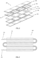
- FIG. 2 1 shows a schematic exploded view of an energy storage module 100.
- the energy storage module 100 has a multiplicity of energy storage cells 10 which are electrically connected in series.
- the energy storage module 100 has a housing 20 which is made of plastic at least in some areas, preferably completely.
- a barrier layer is provided at least in regions, in particular completely, between the housing 20 and the multiplicity of energy storage cells 10 .
- the barrier layer is understood to mean a layer which prevents gases and/or liquids from the environment from being able to enter the housing 20 of the energy storage module 100 or gases and/or liquids from being able to escape from the housing 20 into the environment .
- the "barrier layer” means a layer that is impermeable to gases in the ambient air, to gases that arise during operation of the energy storage module 100 and to moisture in the environment.
- the barrier layer is composed of metal, metal oxide and/or.
- the metal can be or comprise a light metal, in particular aluminum and/or an aluminum alloy or magnesium and/or a magnesium alloy.
- a light metal in particular aluminum and/or an aluminum alloy or magnesium and/or a magnesium alloy.
- any layer that prevents the passage of gas and liquid through the plastic and does not change the electrochemical properties of the cell is suitable as a barrier layer.
- the barrier layer can be materially connected at least in regions to the inner surfaces of the housing, in particular to the inner surfaces of the lower housing shell 20b and the upper housing shell 20a. This is preferably done via chemical vapor deposition or physical vapor deposition.
- the barrier layer can at least partially, in particular completely, be formed as a film which is connected to the inner surfaces of the housing, in particular the lower housing shell 20b and the upper housing shell 20a.
- This is preferably a metal foil which is materially bonded to the inner surfaces of the housing 20 .
- FIG. 2 also indicates that each energy storage cell 10 has a connecting element 11a, 11b on two opposite sides.
- a first connecting element 11a can correspond to a positive contact of the energy storage cell 10 and a second connecting element 11b to a negative contact of the energy storage cell 10.
- connecting elements 11a, 11b can be formed from a metal foil, in particular a copper foil or an aluminum foil.
- two directly adjacent energy storage cells 10 can be connected to one another via a respective connecting element 11a, 11b of these energy storage cells 10.
- Two directly adjacent energy storage cells 10 are preferably connected by welding a respective connecting element 11a, 11b of the energy storage cells 10 to be connected.
- the connecting elements 11a, 11b of the two directly adjacent energy storage cells 10 form an overlapping area in which the welding takes place. It should be noted here that the connection of two directly adjacent energy storage cells 10 via a respective connecting element 11a, 11b of the energy storage cells 10 is carried out in such a way that a flexible and/or bendable connection point is formed.
- connecting the plurality of energy storage cells 10 via their connecting elements 11a, 11b eliminates the need to provide a busbar.
- At least one film 30 made of plastic can be provided.
- the film 30 made of plastic is arranged between the plurality of energy storage cells 10 and the housing 20, or the lower housing shell 20b and the upper housing shell 20a.
- the film 30 made of plastic can also be preformed, in particular plastically preformed and preferably thermoformed, in such a way that the film 30 made of plastic has a multiplicity of indentations which are each designed to accommodate an energy storage cell 10 .
- a lower film 30b made of plastic, which is arranged between the lower housing shell 20b and the plurality of energy storage cells 10, and an upper film 30a made of plastic, which is arranged between the upper housing shell 20a and the plurality of energy storage systems 1000, are preferably provided.
- the at least one film 30 can be made, for example, from acrylic butadiene styrene, polycarbonate, polyamide, polyvinyl chloride, polyethylene terephthalate, polyoxymethylene, polyolefin, such as. B. polypropylene and / or polyethylene, or a copolymer thereof.
- the at least one film 30 made of plastic can have recesses in areas where the connecting elements 11a, 11b of the energy storage cells 10 are arranged. These recesses serve on the one hand that further production steps, for example connecting two directly adjacent energy storage cells 10 via their connecting elements 11a, 11b can be carried out more easily, and on the other hand that the monitoring of the individual cells can be simplified by contacting the connecting elements 11a, 11b with a measuring line 40.
- a measuring line 40 can be provided in an energy storage module 100 .
- This measuring line 40 can be integrated, for example, in the plastic film 30, in particular in the upper plastic film 30a, or in the housing 20, in particular in the upper housing shell 20a.
- the measuring line 40 can determine a state of an energy storage cell 10 , of a plurality of energy storage cells 10 and/or of all of the plurality of energy storage cells 10 .
- the measuring line 40 can determine a voltage and/or a current flow and/or a capacitance thereof.
- the energy storage module 100 which is shown schematically in FIG. 2 is shown has four energy storage cells 10 . However, it should be noted that the number of energy storage cells 10 of an energy storage module 100 depends on the desired power density of the energy storage module 100 . An energy storage module 100 with more or fewer energy storage cells 10 can also be conceivable.
- FIG. 3 shows a schematic representation of an energy storage module 100, which is designed as a cell stack 100 '.
- the energy storage module 100 which is initially aligned essentially horizontally, that is to say that the individual energy storage cells 10 lie essentially horizontally next to one another, is bent via the connecting elements 11a, 11b of the energy storage cells 10 in such a way that the energy storage cells 10 of the cell stack 100' are essentially arranged vertically one above the other.
- the connecting elements 11a, 11b of two connected energy storage cells 10 preferably form an at least essentially 180° bend. This bend is also formed by the housing 20 and optionally by the at least one film 30 made of plastic, specifically at points in which the connecting elements 11a, 11b of the energy storage cells 10 are accommodated.
- FIG. 4 shows a schematic representation of an energy storage system 1000, which has a system housing 1200 and a cell stack 100' designed Energy storage module 100 has.
- a cover was not shown for better illustration.
- the cover which is not shown, has a positive and a negative connection element, which can each be connected to a connection element 11a, 11b of the cell stack 100′ via a contacting element.
- a multiplicity of energy storage modules 100 embodied as a cell stack 100 ′ are arranged in the system housing 1200 .
- the number of energy storage modules 100 depends on the desired total capacity of the energy storage system 1000.
- each energy storage cell 10 can have at least one filling and/or degassing hole.
- the filling and/or degassing hole is advantageously designed in such a way that it can be closed again, preferably hermetically, with a plug. It is also conceivable to close the filling and/or degassing hole again using a membrane, which is preferably designed as a bursting membrane.
- a membrane is characterized in particular by the fact that it is impermeable to gases and/or liquids and represents protection in that it bursts if an internal pressure of the energy storage cell exceeds a previously determined or determinable value.
- FIG. 5 1 is a schematic representation of the process for manufacturing an energy storage module 100, which is a continuous process.
- a magazine 10 ′ is shown, which contains a large number of energy storage cells 10 .
- a reel 20' on which a supply of the housing 20 is wound, in particular a reel 20b' on which a lower housing shell 20b is wound as an endless belt, and a reel 20a' on which an upper housing shell 20a is wound as an endless belt is.
- the housing 20, or the lower housing shell 20b and the upper housing shell 20a is preferably preformed in such a way that the housing 20, or the lower housing shell 20b or the upper housing shell 20a, has a large number of indentations, which are designed to accommodate one energy storage cell 10 each.
- a barrier layer is particularly preferably arranged on housing 20, or the lower housing shell 20b or the upper housing shell 20a, specifically on a surface of the housing, or the lower housing shell 20b or the upper housing shell 20a, specifically in Direction of the plurality of energy storage cells 10.
- the direction of manufacture is indicated here by the arrow F.
- the barrier layer prevents gases and/or liquids from penetrating into the energy storage module 100 via the housing 20 or gases and/or liquids from escaping via the housing 20 .
- the barrier layer is made up of metal, metal oxide and/or silicates.
- the metal can be or comprise a light metal, in particular aluminum and/or an aluminum alloy or magnesium and/or a magnesium alloy.
- the barrier layer can be materially connected at least in regions to the inner surfaces of the housing, in particular to the inner surfaces of the lower housing shell 20b and the upper housing shell 20a. This is preferably done via chemical vapor deposition or physical vapor deposition.
- the barrier layer can at least partially, in particular completely, be formed as a film which is connected to the inner surfaces of the housing, in particular the lower housing shell 20b and the upper housing shell 20a.
- This is preferably a metal foil which is materially bonded to the inner surfaces of the housing 20 .
- At least one roll 30' is provided with a supply of plastic film as an endless strip.
- the lower plastic film 30b is unrolled from the roll 30b' with the lower plastic film 30b and preformed in a first step (S1b).
- the preforming of the lower film 30b from plastic is in particular a plastic preforming, the preforming preferably takes place via a thermoforming step.
- the lower film 30b is preformed from plastic in such a way that a large number of indentations are introduced.
- one energy storage cell 10 is provided from the magazine 10′ of energy storage cells 10 in a feed direction L in such a way that one energy storage cell 10 is arranged in a depression in the lower plastic film 30b.
- the supply direction of the energy storage cells 10 is indicated here by the arrow L.
- An upper film 30a made of plastic is then provided from a roll 30a' with a film supply and preformed in accordance with the lower film 30b made of plastic (S1a).
- the preformed foil 30a can now be arranged on the multiplicity of energy storage cells 10 in such a way that one energy storage cell 10 is arranged in a depression in the upper plastic foil 30a. Subsequently, connecting elements 11a, 11b of two directly adjacent energy storage cells 10 are connected to one another (S2) through recesses in the upper and lower plastic film 30a, 30b. This is preferably done via a welding process. It should be noted that a flexible and/or bendable connection point is formed.
- the lower housing shell 20b is provided as an endless belt from the reel 20b' with the lower housing shell supply
- the upper housing shell 20a is provided as an endless belt from the reel 20a' with the upper housing shell supply, in such a way that the lower housing shell 20b and the upper housing shell 20a enclose the lower film 30b made of plastic and the upper film 30a made of plastic and the plurality of energy storage cells 10.
- a barrier layer is particularly preferably already provided on the lower or upper housing shell 20a, 20b, which is also already preformed.
- the top and bottom shells 20a, 20b are fed such that indentations in the bottom and top shells 20a, 20b accommodate the indentations in the bottom and top plastic sheets 30a, 30b and the energy storage cells 10, respectively.
- an energy storage module 100 can be bent.
- the multiplicity of energy storage cells 10 are not arranged on a film 30 made of plastic, but directly in the housing.
- the individual energy storage cells 10 are each formed with a cell housing.
- the energy storage cells 10 from the magazine are first placed on a conveyor belt and connected to one another on this via the connecting elements 11a, 11b of two adjacent energy storage cells 10.
- the connected energy storage cells 10 are then arranged in the housing 20, or the lower housing shell 20b and the upper housing shell 20a, and then divided into energy storage modules 100 via a cutting process.
- a measuring line 40 can be integrated into the upper or lower plastic film 30a, 30b, for example. Likewise, such a measuring line 40 can be integrated into the upper or into the lower housing shell 20a, 20b.
Landscapes
- Chemical & Material Sciences (AREA)
- Chemical Kinetics & Catalysis (AREA)
- Electrochemistry (AREA)
- General Chemical & Material Sciences (AREA)
- Engineering & Computer Science (AREA)
- Manufacturing & Machinery (AREA)
- Materials Engineering (AREA)
- Sealing Battery Cases Or Jackets (AREA)
- Battery Mounting, Suspending (AREA)
Description
- Die vorliegende Anmeldung betrifft ein kontinuierliches Fertigungsverfahren für ein Energiespeichermodul.
- Üblicherweise wird bei der Herstellung von Energiespeichermodulen zunächst eine Vielzahl von Energiespeicherzellen produziert. Hierfür wird eine Vielzahl von Elektroden und Separatoren innerhalb eines Zellengehäuses angeordnet und verschlossen. Anschließend müssen die einzelnen Energiespeicherzellen in einem Modulgehäuse angeordnet und elektrisch verbunden werden. Dies geschieht herkömmlicherweise über eine Sammelschiene, welche mit den einzelnen Zellen elektrisch leitfähig verbunden werden muss, insbesondere durch Verschweißen. Erst dann kann das Energiespeichermodul verschlossen werden und beispielsweise in ein Energiespeichersystem eingebaut werden.
- Ein solches Herstellungsverfahren weist allerdings den Nachteil auf, dass es durch die hohe Anzahl an voneinander unabhängigen Fertigungsschritten sowohl zeitintensiv, als auch aufwendig ist. Dies steigert darüber hinaus die Kosten für das Herstellungsverfahren, genauso wie die Kosten für das Energiespeichersystem beziehungsweise das Energiespeichermodul.
- Vorbekannte Herstellungsverfahren gattungsgemäßer Energiespeichermodule werden unter anderen in der
WO 2015/140952 A1 bzw.EP 3 121 881 A1 ,US 2015/064521 A1 ,JP 2004-071302 A US 2016/248052 A1 offenbart. - Der Erfindung liegt daher die Aufgabe zugrunde, ein Herstellungsverfahren für ein verbessertes, leistungsstarkes und platzsparendes Energiespeichermodul bereitzustellen, welches die Nachteile des Standes der Technik nicht aufweist und einfach und kostengünstig ist.
- Im Hinblick auf das Verfahren zum Herstellen eines solchen Energiespeichermoduls wird die der Erfindung zugrunde liegende Aufgabe erfindungsgemäß durch den Gegenstand des nebengeordneten Patentanspruchs 1 gelöst. Vorteilhafte Weiterbildungen sind in den abhängigen Patentansprüchen angegeben.
- Demnach wird ein Energiespeichermodul, welches über ein kontinuierliches Fertigungsverfahren hergestellt ist, angegeben. Das Energiespeichermodul weist hierbei eine Vielzahl von elektrisch in Reihe geschalteten Energiespeicherzellen und ein zumindest bereichsweise, und vorzugsweise vollständig, aus Kunststoff gefertigtes Gehäuse auf. Die Vielzahl von Energiespeicherzellen sind in dem Gehäuse aufnehmbar bzw. aufgenommen. Zwischen dem Gehäuse und der Vielzahl von Energiespeicherzellen ist zumindest bereichsweise, vorzugsweise vollständig, eine Barriereschicht angeordnet.
- Unter der Barriereschicht ist eine Schicht zu verstehen, die verhindert, dass Gase und/oder Flüssigkeiten in das Gehäuse eintreten bzw. aus dem Gehäuse austreten können. Die Barriereschicht kann dabei aus Metall, Metalloxid und/oder Silikaten ausgebildet sein. Bevorzugt wird eine Barriereschicht aus einem Leichtmetall, insbesondere Aluminium und/oder einer Aluminiumlegierung verwendet.
- Die Vorteile der Erfindung liegen auf der Hand. Ein solches Energiespeichermodul weist zunächst den Vorteil auf, dass diverse Funktionalitäten in das Energiespeichermodul integriert werden, und dadurch sowohl die Produktkosten als auch die Fertigungskosten gesenkt werden können. Dies wird zudem durch das erfindungsgemäße, einfache und schnelle Fertigungsverfahren unterstützt. Durch das Anwenden eines kontinuierlichen Fertigungsverfahrens kann eine hohe Anzahl an Energiespeichermodulen in kurzer Zeit hergestellt werden, was im Vergleich zu einer diskontinuierlichen Fertigung weniger aufwendig und zugleich weniger kostenintensiv ist. Des Weiteren können vorteilhafterweise kostengünstige und gut verformbare Materialien, insbesondere Kunststoffe, für das Gehäuse verwendet werden. Beispielsweise kann ein Acryl-Butadien-Styrol, Polycarbonat, Polyamid, Polyvinylchlorid, Polyethylenterephthalat, Polyoxymethylen, Polyolefin oder ein Copolymer hiervon gewählt werden, bevorzugt ein Polyolefin Copolymer wie beispielsweise ein Polypropylen-Polyethylen-Copolymer. Mithilfe der Barriereschicht ist das Gehäuse dabei vorteilhafterweise dennoch gegen Gase und/oder Flüssigkeiten undurchlässig.
- Gemäß Erfindung weist das Gehäuse eine obere Gehäuseschale und eine untere Gehäuseschale auf. Dies vereinfacht ferner die Herstellung des Energiespeichermoduls, da das Gehäuse zum einen einfacher herzustellen und zum anderen einfacher anzuordnen ist. Dadurch können die Produktkosten und Fertigungskosten weiterhin gesenkt werden.
- Gemäß einem weiteren Aspekt der Erfindung kann das Gehäuse die Vielzahl von Energiespeicherzellen hermetisch einschließen. Dadurch erhöht sich vorteilhafterweise die Sicherheit des Energiespeichermoduls, da eine Verpuffungs- und Brandgefahr, welche durch einen Feuchtigkeitseintritt in das Energiespeichermodul hervorgerufen werden kann, durch eine hermetische Abdichtung des Energiespeichermoduls von der Umgebung vorteilhafterweise verhindert werden kann.
- Gemäß einem weiteren Aspekt der Erfindung kann das Gehäuse vorgeformt sein, insbesondere plastisch vorgeformt, und zwar derart, dass das Gehäuse eine Vielzahl von Vertiefungen aufweist, welche jeweils dazu ausgelegt sind, eine Energiespeicherzelle aufzunehmen. Insbesondere ist das Gehäuse thermogeformt. Dies führt vorteilhafterweise zu einer einfacheren Fertigung, da mit Hilfe der Vertiefungen die Energiespeicherzellen automatisch richtig angeordnet werden können. Dadurch entfällt ein weiterer Positionierungs- und Ausrichtungsschritt. Des Weiteren kann das Gehäuse über kostengünstige Fertigungsverfahren vorgeformt werden, was wiederum zu einer Reduzierung der Produkt- und Fertigungskosten führt.
- Erfindungsgemäß weist jede Energiespeicnerzelle aut zwei sich gegenüberliegenden Seiten Jeweils ein Verbindungselement auf, über das nebeneinander angeordnete Energiespeicherzellen miteinander verbunden oder verbindbar sind. Insbesondere kann es sich bei dem Verbindungselement um ein flexibles und/oder biegbares Verbindungselement handeln. Bevorzugt können nebeneinander angeordnete Energiespeicherzellen über deren Verbindungselemente verschweißt werden, und zwar derart, dass eine flexible und/oder biegbare Verbindungsstelle ausgebildet wird. Dadurch wird vorteilhafterweise das elektrische Kontaktieren von nebeneinander angeordneten Energiespeicherzellen vereinfacht, insbesondere das in Reihe Schalten der Energiespeicherzellen. Dies führt zu einer einfacheren Herstellung des Energiespeichermoduls, was wiederum mit einer Reduzierung der Kosten einhergeht.
- Gemäß einem weiteren Aspekt der Erfindung kann das das Gehäuse und die Vielzahl von Energiespeicherzellen einen Zellenstapel ausbilden, und zwar dadurch, dass die Verbindungselemente jeweils derart gebogen sind, dass zwei benachbarte Zellen übereinander angeordnet sind. Das heißt, dass die Vielzahl von Energiespeicherzellen, welche zuvor zumindest im Wesentlichen horizontal nebeneinanderliegend angeordnet waren, einen Zellenstapel ausbilden, bei dem die Vielzahl von Energiespeicherzellen nun zumindest im Wesentlichen vertikal übereinander gestapelt sind, wobei direkt übereinanderliegende Energiespeicherzellen weiterhin über die nun verbogenen Verbindungselemente verbunden sind.
- Dies führt vorteilhafterweise dazu, dass die Energiespeicherzellen des Energiespeichermoduls platzsparend angeordnet sind, und dadurch insbesondere die Gesamtgröße des Energiespeichermoduls bzw. damit auch eines Energiespeichersystems, welches mindestens ein Energiespeichermodul aufweist, dabei möglichst klein gehalten werden kann.
- Gemäß einem weiteren Aspekt der Erfindung kann das Energiespeichermodul ferner mindestens eine Folie aus Kunststoff aufweisen, welche zumindest bereichsweise zwischen dem Gehäuse und den Energiespeicherzellen vorgesehen ist, vorzugsweise jeweils zwischen der unteren und der oberen Gehäuseschale und der Vielzahl von Energiespeicherzellen vorgesehen ist. Dies birgt den Vorteil, dass die Energiespeicherzellen ferner vor Umgebungseinflüssen mit Hilfe der Folie aus Kunststoff geschützt werden können. Dabei kann die Folie aus Kunststoff aus kostengünstigem und einfach verarbeitbarem Kunststoff, wie beispielsweise Polyamid, Polyethylenterephthalat, Polypropylen, und/oder Polyethylen gefertigt sein.
- Durch das Verwenden eines Kunststoffes wird darüber hinaus auch das Gewicht des Energiespeichermoduls vorteilhafterweise nicht in die Höhe getrieben. Ferner bleibt es kostengünstig und einfach herzustellen.
- Gemäß einem weiteren Aspekt kann die Folie aus Kunststoff Ausnehmungen aufweisen, und zwar an Stellen, an welchen die Verbindungselemente angeordnet sind. Dadurch wird vorteilhafterweise eine einfache Möglichkeit geboten, Kontaktpunkte mit beispielsweise einer Messleitung auszubilden, sowie einen Zugang zu den Verbindungselementen für etwaige Weiterverarbeitungsschritte, wie beispielsweise ein Verbinden zweier direkt benachbarter Energiespeicherzellen über deren Verbindungselemente.
- Gemäß einem weiteren Aspekt der Erfindung kann die Folie aus Kunststoff vorgeformt sein, insbesondere plastisch vorgeformt, vorzugsweise thermogeformt, und zwar derart, dass die Folie eine Vielzahl von Vertiefungen aufweist, welche jeweils dazu ausgelegt sind, eine Energiespeicherzelle aufzunehmen. Dies ermöglicht vorteilhafterweise eine einfache Anordnung und Ausrichtung sowohl der Energiespeicherzellen in der Folie, als auch der Folie in dem Gehäuse, bzw. der oberen und unteren Gehäuseschale. Damit geht auch eine einfache Herstellung einher, welche auch zu einer Reduzierung der Verfahrenskosten führen kann. Gemäß einem weiteren Aspekt der Erfindung können die Energiespeicherzellen als Jelly-Rolls ausgebildet sein. Jelly-Roll-Zellen stellen hierbei vorteilhafte platzsparende, sowie gewichtseinsparende Energiespeicherzellen dar, welche dennoch eine relativ hohe Leistungsdichte aufweisen.
- Gemäß einem weiteren Aspekt der Erfindung können die Energiespeicherzellen Lithium-Ionen-Zellen sein. Vorteilhafterweise können Lithium-Ionen-Zellen eine relativ hohe Leistungsdichte aufweisen.
- Gemäß einem weiteren Aspekt kann das Energiespeichermodul eine Messleitung aufweisen, welche vorzugsweise in dem Gehäuse oder in der Folie aus Kunststoff integriert ist. Über eine solche Messleitung kann das Energiespeichermodul vorteilhafterweise einfach überwacht werden, was zu einer Erhöhung der Sicherheit und Leistungsfähigkeit des Energiespeichermoduls bzw. zur Beurteilung der Leistungsfähigkeit des Energiespeichermoduls führen kann.
- Gemäß einem weiteren Aspekt kann die Messleitung einen Zustand, insbesondere eine Spannung und/oder einen Stromfluss und/oder eine Kapazität, einer Energiespeicherzelle, von mehreren Energiespeicherzellen, und/oder von allen der Vielzahl von Energiespeicherzellen bestimmen. Vorteilhafterweise können hierbei die wichtigsten Parameter, über welche auf den Zustand des Energiespeichermoduls geschlossen werden kann, überwacht werden. Dadurch wird die Funktionsfähigkeit des Energiespeichermoduls ständig überwacht und sichergestellt.
- Gemäß einem weiteren Aspekt der Erfindung kann jede Energiespeicherzelle mindestens ein Füllloch und/oder Entgasungsloch aufweisen. Insbesondere kann das mindestens eine Füll- und/oder Entgasungsloch wieder verschließbar bzw. wieder hermetisch verschließbar ausgebildet sein. Dadurch wird vorteilhafterweise die Handhabung einer Speicherzelle vereinfacht.
- Gemäß einem weiteren Aspekt ist ein Energiespeichersystem angegeben, insbesondere zum Einsatz in einem Fahrzeug. Das Energiespeichersystem weist dabei mindestens ein oben beschriebenes Energiespeichermodul und ein Systemgehäuse auf, wobei das mindestens Energiespeichermodul innerhalb des Systemgehäuses angeordnet ist. Dabei wird vorteilhafterweise ein einfach und kostengünstig zu fertigendes Energiespeichersystem angegeben.
- Im Hinblick auf das Verfahren zum Herstellen eines Energiespeichermoduls, insbesondere eines oben beschriebenen Speichermoduls handelt es sich hierbei erfindungsgemäß um ein kontinuierliches Fertigungsverfahren. Dies liefert den Vorteil, dass das Energiespeichermodul bzw. eine Vielzahl von Energiespeichermodulen schnell und kostengünstig hergestellt werden können. Dies ist zudem im Vergleich zu einer diskontinuierlichen Fertigung weniger aufwendig. Des Weiteren können vorteilhafterweise kostengünstige und gut verformbare Materialien, insbesondere Kunststoffe, für das Gehäuse verwendet werden. Beispielsweise kann ein Acryl-Butadien-Styrol, Polycarbonat, Polyamid, Polyvinylchlorid, Polyethylenterephthalat, Polyoxymethylen, Polyolefin oder ein Copolymer hiervon gewählt werden.
- Erfindungsgemäß weist das Vertanren ferner folgende Schritte auf, und zwar das Bereitstellen einer unteren Gehauseschale aus Kunststoff als Endlosband, das Anordnen von einer Vielzahl von Energiespeicherzellen mit jeweils einer ersten Oberfläche der Energiespeicherzellen auf der unteren Gehäuseschale und Bereitstellen einer oberen Gehäuseschale aus Kunststoff als Endlosband, und zwar auf einer zweiten Oberfläche der Energiespeicherzellen, welche der ersten Oberfläche gegenüberliegt. Dabei ist jeweils zwischen der unteren und oberen Gehäuseschale und der Vielzahl von Energiespeicherzellen eine Barriereschicht angeordnet. Dies senkt vorteilhafterweise die Verfahrensdauer und damit die Produktionskosten. Mithilfe der Barriereschicht ist das Gehäuse dabei vorteilhafterweise dennoch gegen Gase und/oder Flüssigkeiten undurchlässig.
- Gemäß einem weiteren Aspekt der Erfindung kann das Verfahren ferner die folgende Schritte aufweisen, und zwar Bereitstellen und Thermoformen von jeweils mindestens einer Folie aus Kunststoff, und zwar derart, dass eine Vielzahl von Vertiefungen ausgebildet ist, wobei jeweils eine Vertiefung dazu ausgelegt ist, eine Energiespeicherzelle aufzunehmen. Dabei ist jeweils eine Folie aus Kunststoff zwischen der unteren und oberen Gehäuseschale und der Vielzahl von Energiespeicherzellen vorgesehen. Insbesondere ist jeweils eine Folie aus Kunststoff zwischen der Barriereschicht und der Vielzahl von Energiespeicherzellen vorgesehen.
- Dies birgt den Vorteil, dass die Energiespeicherzellen ferner vor Umgebungseinflüssen mit Hilfe der Folie aus Kunststoff geschützt werden können. Dabei kann die Folie aus Kunststoff aus kostengünstigem und einfach verarbeitbarem Kunststoff, wie beispielsweise Polyamid, Polyethylenterephthalat, Polypropylen, und/oder Polyethylen gefertigt sein. Durch das Verwenden eines Kunststoffes wird darüber hinaus auch das Gewicht des Energiespeichermoduls vorteilhafterweise nicht in die Höhe getrieben. Ferner bleibt es kostengünstig und einfach herzustellen.
- Erfindungsgemäß sind direkt benachbarte Energiespeicherzellen über Verbindungselemente, welche jeweils an zwei sich gegenüberliegenden Seiten der Energiespeicherzellen angeordnet sind, miteinander verbunden, und zwar derart, dass die Energiespeicherzellen elektrisch in Reihe geschaltet werden. Insbesondere können direkt benachbarte Energiespeicherzellen durch Verschweißen der Verbindungselemente dieser Energiespeicherzellen verbunden werden. Dabei handelt es sich bei dem Verbindungselement um ein flexibles und/oder biegbares Verbindungselement.
- Dabei werden nebeneinander angeordnete Energiespeicherzellen über deren Verbindungselemente verschweißt, und zwar derart, dass eine flexible und/oder biegbare Verbindungsstelle ausgebildet wird. Dies liefert den Vorteil, dass dadurch das elektrische Kontaktieren von nebeneinander angeordneten Energiespeicherzellen vereinfacht werden kann, insbesondere das in Reihe Schalten der Energiespeicherzellen. Dies führt zu einer einfacheren Herstellung des Energiespeichermoduls, was wiederum mit einer Reduzierung der Kosten einhergeht.
- Gemäß einem weiteren Aspekt der Erfindung kann eine vorbestimmte oder vorbestimmbare Anzahl an verbundenen Zellen abgetrennt werden, wobei zumindest das Gehäuse und die Vielzahl von Energiespeicherzellen einen Zellenstapel ausbilden, und zwar derart, dass jeweils zwei direkt benachbarte Energiespeicherzellen über die dazugehörigen Verbindungselemente derart gebogen werden, dass sie übereinander angeordnet sind, insbesondere derart, dass eine schlangenlinienförmige Biegelinie ausgebildet wird. Dies liefert den Vorteil, dass die Energiespeicherzellen des Energiespeichermoduls platzsparend angeordnet werden können, und dadurch insbesondere die Gesamtgröße des Energiespeichermoduls bzw. damit auch eines Energiespeichersystems, welches mindestens ein Energiespeichermodul aufweist, dabei möglichst klein gehalten werden kann.
- Die Erfindung wird nachstehend, auch hinsichtlich weiterer Merkmale und Vorteile, anhand der Beschreibung von Ausführungsformen unter Bezugnahme auf die beiliegenden Zeichnungen näher erläutert.
- Diese zeigen in:
- FIG. 1
- eine schematische Darstellung eines Fahrzeugs;
- FIG. 2
- eine schematische Darstellung eines Energiespeichermoduls gemäß der vorliegenden Erfindung;
- FIG. 3
- eine schematische Darstellung eines Zellenstapels gemäß der vorliegenden Erfindung;
- FIG. 4
- eine schematische Darstellung eines Zellenstapels, welcher in einem Modulgehäuse angeordnet ist; und
- FIG. 5
- eine schematische Darstellung des Fertigungsverfahrens eines Energiespeichermoduls.
- Nachfolgend wird ein Energiespeichermodul sowie das erfindungsgemäße Verfahren zum Herstellen eines solchen Energiespeichermoduls unter Bezugnahme auf die Darstellungen in den
FIGS. 1 bis 5 genauer beschrieben. Gleiche oder gleichwirkende Elemente und Funktionen sind mit demselben oder ähnlichen Bezugszeichen versehen. - Mit der fortwährend steigenden Anzahl an elektrischen Energieverbrauchern, sowie der Weiterentwicklung der Fahrzeuge 2000 in Richtung von Elektrofahrzeugen und/oder Hybrid-Fahrzeugen, werden vermehrt Energiespeichersysteme mit einer relativ hohen Leistungsdichte gefordert, welche darüber hinaus schnell und kostengünstig zu fertigen sind. Des Weiteren ist es aber genauso denkbar, das erfindungsgemäße Energiespeichermodul 100 in Bereichen einzusetzen, in denen eine relativ hohe Leistungsdichte des Energiespeichermoduls 100 bzw. des Energiespeichersystems 1000 bei geringem Einbauplatz und zu niedrigen Preisen fordert wird.
- Im Folgenden bedeutet "nebeneinander" zumindest im Wesentlichen in horizontaler Richtung, und "übereinander" zumindest im Wesentlichen vertikaler Richtung.
FIG. 1 zeigt eine schematische Darstellung eines Fahrzeugs 2000, welches mindestens ein Energiespeichersystem 1000 aufweist. Das Energiespeichersystem 1000 weist ferner mindestens ein Energiespeichermodul 100 mit einer Vielzahl von Energiespeicherzellen 10 auf. Das Energiespeichersystem 1000 kann hierbei in einem in Fahrtrichtung vorderen Bereich des Fahrzeugs 2000, in einem hinteren Bereich des Fahrzeugs 2000 und/oder in einem Bereich unterhalb der Sitze, insbesondere unterhalb des Fahrersitzes angeordnet sein. - Das Fahrzeug 2000 kann ein Luft- oder Wasserfahrzeug, ein spurgeführtes Fahrzeug, ein Geländefahrzeug, oder bevorzugt ein Straßenfahrzeug sein, wobei unter Straßenfahrzeug ein Personenkraftwagen, ein Lastkraftwagen, ein Bus oder ein Wohnmobil verstanden werden kann.
- Das Fahrzeug 2000 wird durch eine Antriebseinheit angetrieben. Die Antriebseinheit kann einen Verbrennungsmotor, einen Elektromotor oder eine Kombination davon umfassen. Ein Fahrzeug 2000, welches ausschließlich mit einem Elektromotor angetrieben wird, wird als Elektro-Fahrzeug bezeichnet. Ein Fahrzeug 2000, welches sowohl einen Elektromotor, als auch einen Verbrennungsmotor aufweist, wird als Hybrid-Fahrzeug bezeichnet. Hybrid-Fahrzeuge können ferner in Mikrohybrid-Fahrzeuge, Mildhybrid-Fahrzeug, Vollhybrid-Fahrzeuge und/oder Plug-In-Hybrid-Fahrzeuge untergliedert werden. Hierbei kann unter Plug-In-Hybrid-Fahrzeugen jedwedes Hybridfahrzeug verstanden werden, welches nicht nur über den Verbrennungsmotor aufgeladen wird, sondern ebenfalls über das Stromnetz geladen werden kann. Unter Vollhybrid-Fahrzeugen werden Fahrzeuge verstanden, die allein über den Elektromotor angetrieben werden können. Mikrohybrid-Fahrzeuge verfügen über eine Start-Stopp-Funktionalität, und vorzugsweise ebenso über eine Stopp-In-Motion-Funktionalität. Des Weiteren können Mikrohybrid-Fahrzeuge das Energiespeichersystem 1000 über eine sogenannte Bremsenergierückgewinnung aufgeladen werden. Mildhybrid-Fahrzeuge können darüber hinaus über eine Boost-Funktion verfügen, welche zur Unterstützung des Verbrennungsmotors zur Leistungssteigerung verwendet wird.
-
FIG. 2 zeigt eine schematische Explosionsdarstellung eines Energiespeichermoduls 100. Demnach weist das Energiespeichermodul 100 eine Vielzahl von Energiespeicherzellen 10 auf, welche elektrisch in Reihe geschaltet sind. Des Weiteren weist das Energiespeichermodul 100 ein Gehäuse 20 auf, das zumindest bereichsweise, vorzugsweise vollständig aus Kunststoff gefertigt ist. Zwischen dem Gehäuse 20 und der Vielzahl von Energiespeicherzellen 10 ist zudem ein zumindest bereichsweise, insbesondere vollständig, eine Barriereschicht vorgesehen. - Unter der Barriereschicht wird im Zuge dieser Anmeldung eine Schicht verstanden, welche verhindert, dass Gase und/oder Flüssigkeiten aus der Umgebung in das Gehäuse 20 des Energiespeichermoduls 100 eintreten können bzw. dass Gase und/oder Flüssigkeiten aus dem Gehäuse 20 in die Umgebung austreten können. Insbesondere ist unter der "Barriereschicht" eine Schicht gemeint, die gegenüber Gasen in der Umgebungsluft, gegenüber Gasen, welche während des Betriebs des Energiespeichermoduls 100 entstehen und gegenüber Feuchtigkeit in der Umgebung undurchlässig ist.
- Die Barriereschicht ist hierbei aus Metall, Metalloxid und/oder aufgebaut.
- Das Metall kann ein Leichtmetall sein bzw. aufweisen, insbesondere Aluminium und/oder eine Aluminiumlegierung oder Magnesium und/oder eine Magnesiumlegierung. Insbesondere ist jegliche Schicht, die den Durchtritt von Gas und Flüssigkeit durch den Kunststoff verhindert und dabei nicht die elektrochemischen Eigenschaften der Zelle verändert, als Barriereschicht geeignet.
- Die Barriereschicht kann zumindest bereichsweise mit Innenflächen des Gehäuses, insbesondere mit Innenflächen der unteren Gehäuseschale 20b und der oberen Gehäuseschale 20a, stoffschlüssig verbunden sein, insbesondere kann die Barriereschicht auf die Innenflächen des Gehäuses 20 gedampft sein. Dies geschieht bevorzugt über chemische Gasphasenabscheidung oder physikalische Gasphasenabscheidung.
- Ebenso kann die Barriereschicht zumindest bereichsweise, insbesondere vollständig, als Folie ausgebildet sein, welche mit den Innenflächen des Gehäuses, insbesondere der unteren Gehäuseschale 20b und der oberen Gehäuseschale 20a, verbunden ist. Bevorzugt handelt es sich hierbei um eine Metallfolie, welche stoffschlüssig mit den Innenflächen des Gehäuses 20 verbunden ist.
-
FIG. 2 deutet ferner an, dass jede Energiespeicherzelle 10 auf zwei sich gegenüberliegenden Seiten jeweils ein Verbindungselement 11a, 11b aufweist. Dabei kann ein erstes Verbindungselement 11a einem positiven Kontakt der Energiespeicherzelle 10 entsprechen und ein zweites Verbindungselement 11b einem negativem Kontakt der Energiespeicherzelle 10. - Ferner können die Verbindungselemente 11a, 11b aus einer Metallfolie gebildet sein, insbesondere einer Kupferfolie oder einer Aluminiumfolie.
- Des Weiteren können zwei direkt benachbarte Energiespeicherzellen 10 über jeweils ein Verbindungselement 11a, 11b dieser Energiespeicherzellen 10 miteinander verbunden werden. Bevorzugt erfolgt die Verbindung zweier direkt benachbarter Energiespeicherzellen 10 durch ein Verschweißen von jeweils einem Verbindungselement 11a, 11b der zu verbindenden Energiespeicherzellen 10. Dabei bilden die Verbindungselemente 11a, 11b der zwei direkt benachbarten Energiespeicherzellen 10 einen Überlappungsbereich aus, in welchem das Verschweißen erfolgt. Dabei ist zu beachten, dass das Verbinden zweier direkt benachbarter Energiespeicherzellen 10 über jeweils ein Verbindungselement 11a, 11b der Energiespeicherzellen 10 derart ausgeführt wird, dass eine flexible und/oder biegbare Verbindungsstelle ausgebildet wird.
- Vorteilhafterweise entfällt durch das Verbinden der Vielzahl von Energiespeicherzellen 10 über deren Verbindungselemente 11a, 11b die Notwendigkeit, eine Sammelschiene vorzusehen.
- Ferner kann mindestens eine Folie 30 aus Kunststoff vorgesehen sein. Die Folie 30 aus Kunststoff ist dabei zwischen der Vielzahl von Energiespeicherzellen 10 und dem Gehäuse 20, bzw. der unteren Gehäuseschale 20b und der oberen Gehäuseschale 20a, angeordnet. Die Folie 30 aus Kunststoff kann ferner vorgeformt sein, insbesondere plastisch vorgeformt und bevorzugt thermogeformt sein, und zwar derart, dass die Folie 30 aus Kunststoff eine Vielzahl von Vertiefungen aufweist, welche dazu ausgelegt sind, jeweils eine Energiespeicherzelle 10 aufzunehmen. Bevorzugt wird eine untere Folie 30b aus Kunststoff, welche zwischen der unteren Gehäuseschale 20b und der Vielzahl von Energiespeicherzellen 10 angeordnet ist, und eine obere Folie 30a aus Kunststoff, welche zwischen der oberen Gehäuseschale 20a und der Vielzahl von Energiespeichersystemen 1000 angeordnet ist, vorgesehen. Die mindestens eine Folie 30 kann dabei beispielsweise aus Acryl-Butadien-Styrol, Polycarbonat, Polyamid, Polyvinylchlorid, Polyethylenterephthalat, Polyoxymethylen, Polyolefin, wie z. B. Polypropylen und/oder Polyethylen, oder einem Copolymer hiervon gefertigt sein.
- Des Weiteren kann die mindestens eine Folie 30 aus Kunststoff in Bereichen, an denen die Verbindungselemente 11a, 11b der Energiespeicherzellen 10 angeordnet sind, Ausnehmungen aufweisen. Diese Ausnehmungen dienen zum einen dazu, dass weitere Fertigungsschritte, beispielsweise das Verbinden zweier direkt benachbarter Energiespeicherzellen 10 über deren Verbindungselemente 11a, 11b, einfacher durchgeführt werden können, und zum anderen, dass die Überwachung der einzelnen Zellen durch Kontaktierung der Verbindungselemente 11a, 11b mit einer Messleitung 40 vereinfacht werden kann.
- Ferner kann eine Messleitung 40 in einem Energiespeichermodul 100 vorgesehen sein. Diese Messleitung 40 kann beispielsweise in der Folie 30 aus Kunststoff, insbesondere in der oberen Folie 30a aus Kunststoff, oder in dem Gehäuse 20, insbesondere in der oberen Gehäuseschale 20a, integriert sein. Die Messleitung 40 kann dabei einen Zustand einer Energiespeicherzelle 10, von mehreren Energiespeicherzellen 10 und/oder von allen der Vielzahl von Energiespeicherzellen 10 bestimmen. Insbesondere kann die Messleitung 40 eine Spannung und/oder einen Stromfluss und/oder eine Kapazität davon ermitteln.
- Das Energiespeichermodul 100, welches schematisch in
FIG. 2 gezeigt ist, weist vier Energiespeicherzellen 10 auf. Es ist allerdings zu beachten, dass die Anzahl an Energiespeicherzellen 10 eines Energiespeichermoduls 100 von der gewünschten Leistungsdichte des Energiespeichermoduls 100 abhängt. So kann auch ein Energiespeichermodul 100 mit mehr oder weniger Energiespeicherzellen 10 denkbar sein. -
FIG. 3 zeigt eine schematische Darstellung eines Energiespeichermoduls 100, welches als Zellenstapel 100' ausgebildet ist. Hierfür ist das Energiespeichermodul 100, welches zunächst im Wesentlichen horizontal ausgerichtet ist, d. h., dass die einzelnen Energiespeicherzellen 10 im Wesentlichen horizontal nebeneinander liegen, über die Verbindungselemente 11a, 11b der der Energiespeicherzellen 10 derart gebogen, dass die Energiespeicherzellen 10 des Zellenstapels 100' im Wesentlichen vertikal übereinander angeordnet sind. Dabei bilden die Verbindungselemente 11a, 11b zweier verbundener Energiespeicherzellen 10 vorzugsweise eine zumindest im Wesentlichen 180° Biegung aus. Diese Biegung wird ebenfalls von dem Gehäuse 20 und gegebenenfalls von der mindestens einen Folie 30 aus Kunststoff ausgebildet, und zwar an Stellen, in denen die Verbindungselemente 11a, 11b der Energiespeicherzellen 10 aufgenommen werden. -
FIG. 4 zeigt eine schematische Darstellung eines Energiespeichersystems 1000, welches ein Systemgehäuse 1200 und ein als Zellenstapel 100' ausgebildetes Energiespeichermodul 100 aufweist. Hierbei wurde auf die Darstellung eines Deckels zur besseren Veranschaulichung verzichtet. Der nicht dargestellte Deckel weist ein positives und ein negatives Anschlusselement auf, welche jeweils über ein Kontaktierungselement mit einem Verbindungselement 11a, 11b des Zellenstapels 100' verbunden werden können. Des Weiteren ist es denkbar, dass eine Vielzahl von als Zellenstapel 100' ausgebildeten Energiespeichermodulen 100 in dem Systemgehäuse 1200 angeordnet sind. Die Anzahl an Energiespeichermodulen 100 ist hierbei abhängig von der gewünschten Gesamtkapazität des Energiespeichersystems 1000. - Auch wenn dies in den Figuren nicht explizit hervorgehoben ist, kann jede Energiespeicherzelle 10 mindestens ein Füll- und/oder Entgasungsloch aufweisen. Das Füll- und/oder Entgasungsloch ist vorteilhafterweise derart ausgebildet, dass es über einen Stopfen wiederverschließbar ist, bevorzugt hermetisch verschließbar ist. Auch ist es denkbar, das Füll- und/oder Entgasungsloch über eine Membran, welche bevorzugt als Berstmembran ausgebildet ist, wieder zu verschließen. Eine solche Membran zeichnet sich insbesondere dadurch aus, dass sie gegen Gase und/oder Flüssigkeiten undurchlässig ist, und einen Schutz insofern darstellt, dass sie platzt wenn ein Innendruck der Energiespeicherzelle einen vorher bestimmten oder bestimmbaren Wert übersteigt.
- In
FIG. 5 ist eine schematische Darstellung des Verfahrens zum Herstellen eines Energiespeichermoduls 100 gezeigt, bei welchem es sich um ein kontinuierliches Verfahren handelt. Dabei ist ein Magazin 10' dargestellt, welches eine Vielzahl von Energiespeicherzellen 10 enthält. Ferner ist eine Rolle 20' dargestellt, auf welcher ein Vorrat des Gehäuses 20 aufgewickelt ist, insbesondere eine Rolle 20b', auf der eine untere Gehäuseschale 20b als Endlosband aufgewickelt ist, und eine Rolle 20a', auf der eine obere Gehäuseschale 20a als Endlosband aufgewickelt ist. Bevorzugt ist das Gehäuse 20, bzw. die untere Gehäuseschale 20b und die obere Gehäuseschale 20a bereits vorgeformt, und zwar derart, dass das Gehäuse 20, bzw. die untere Gehäuseschale 20b bzw. die obere Gehäuseschale 20a, eine Vielzahl von Vertiefungen aufweist, welche dazu ausgelegt sind, je eine Energiespeicherzelle 10 aufzunehmen. Besonders bevorzugt ist auf Gehäuse 20, bzw. der unteren Gehäuseschale 20b oder der oberen Gehäuseschale 20a, eine Barriereschicht angeordnet, und zwar auf einer Oberfläche des Gehäuses, bzw. der unteren Gehäuseschale 20b bzw. der oberen Gehäuseschale 20a, und zwar in Richtung der Vielzahl von Energiespeicherzellen 10. Die Fertigungsrichtung ist hierbei mit dem Pfeil F angedeutet. - Die Barriereschicht verhindert dabei, dass Gase und/oder Flüssigkeiten über das Gehäuse 20 in das Energiespeichermodul 100 eindringen können bzw. dass Gase und/oder Flüssigkeiten über das Gehäuse 20 austreten können.
- Die Barriereschicht ist hierbei aus Metall, Metalloxid und/oder Silikaten aufgebaut. Das Metall kann ein Leichtmetall sein bzw. aufweisen, insbesondere Aluminium und/oder eine Aluminiumlegierung oder Magnesium und/oder eine Magnesiumlegierung.
- Die Barriereschicht kann zumindest bereichsweise mit Innenflächen des Gehäuses, insbesondere mit Innenflächen der unteren Gehäuseschale 20b und der oberen Gehäuseschale 20a, stoffschlüssig verbunden sein, insbesondere kann die Barriereschicht auf die Innenflächen des Gehäuses 20 gedampft sein. Dies geschieht bevorzugt über chemische Gasphasenabscheidung oder physikalische Gasphasenabscheidung.
- Ebenso kann die Barriereschicht zumindest bereichsweise, insbesondere vollständig, als Folie ausgebildet sein, welche mit den Innenflächen des Gehäuses, insbesondere der unteren Gehäuseschale 20b und der oberen Gehäuseschale 20a, verbunden ist. Bevorzugt handelt es sich hierbei um eine Metallfolie, welche stoffschlüssig mit den Innenflächen des Gehäuses 20 verbunden ist.
- Ferner ist mindestens eine Rolle 30', mit einem Folienvorrat aus Kunststoff als Endlosband vorgesehen. Zunachst wird von der Rolle 30b' mit der unteren Folie 30b aus Kunststoff die untere Folie 30b aus Kunststoff abgerollt und in einem ersten Schritt (S1b) vorgeformt. Das Vorformen der unteren Folie 30b aus Kunststoff ist insbesondere eine plastische Vorformung, bevorzugt erfolgt das Vorformen über einen Thermoform-Schritt. Dabei wird die untere Folie 30b aus Kunststoff derart vorgeformt, dass eine Vielzahl von Vertiefungen eingebracht werden.
- Anschließend wird je eine Energiespeicherzelle 10 aus dem Magazin 10' von Energiespeicherzellen 10 in einer Zuführrichtung L derart bereitgestellt, dass jeweils eine Energiespeicherzelle 10 in einer Vertiefung der unteren Folie 30b aus Kunststoff angeordnet wird. Die Zuführrichtung der Energiespeicherzellen 10 ist hierbei mit dem Pfeil L angedeutet.
- Anschließend wird eine obere Folie 30a aus Kunststoff von einer Rolle 30a' mit einem Folienvorrat bereitgestellt und entsprechend der unteren Folie 30b aus Kunststoff vorgeformt (S1a).
- Die vorgeformte Folie 30a kann nun derart auf der Vielzahl von Energiespeicherzellen 10 angeordnet werden, dass je eine Energiespeicherzelle 10 in einer Vertiefung der oberen Folie 30a aus Kunststoff angeordnet wird. Anschließend werden durch Ausnehmungen in der oberen und unteren Folie 30a, 30b aus Kunststoff hinweg Verbindungselemente 11a, 11b zweier direkt benachbarter Energiespeicherzellen 10 miteinander verbunden (S2). Dies erfolgt bevorzugt über einen Schweißvorgang. Dabei ist zu beachten, dass eine flexible und/oder biegbare Verbindungsstelle ausgebildet wird.
- Anschließend wird die untere Gehäuseschale 20b als Endlosband von der Rolle 20b' mit dem unteren Gehäuseschalenvorrat bereitgestellt, und gleichzeitig auch die obere Gehäuseschale 20a als Endlosband von der Rolle 20a' mit dem oberen Gehäuseschalenvorrat bereitgestellt, und zwar derart, dass die untere Gehäuseschale 20b und die obere Gehäuseschale 20a die untere Folie 30b aus Kunststoff und die obere Folie 30a aus Kunststoff sowie die Vielzahl von Energiespeicherzellen 10 umschließen. Dabei ist besonders bevorzugt bereits eine Barriereschicht auf der unteren bzw. oberen Gehäuseschale 20a, 20b vorgesehen, welche auch bereits vorgeformt ist. Die obere und die untere Gehäuseschale 20a, 20b werden derart zugeführt, dass Vertiefungen in der unteren bzw. der oberen Gehäuseschale 20a, 20b die Vertiefungen in der unteren bzw. oberen Folie 30a, 30b aus Kunststoff und die Energiespeicherzellen 10 aufnehmen.
- In einem weiteren Schritt wird die Endlosanordnung von Energiespeicherzellen 10 mit Gehäuse 20 und die mindestens eine Folie 30 aus Kunststoff über einen Schneidevorgang in einzelne Energiespeichermodule 100 mit einer vorbestimmten oder vorbestimmbaren Anzahl an Energiespeicherzellen 10 abgetrennt.
- In einem weiteren Schritt kann ein Energiespeichermodul 100 gebogen werden.
- Dies geschieht derart, dass ein vorher im Wesentlichen horizontal angeordnetes Energiespeichermodul 100 derart gebogen wird, dass ein Zellenstapel 100' ausgebildet wird, bei welchem die Energiespeicherzellen 10 im Wesentlichen vertikal übereinander gestapelt sind.
- Genauso gut ist es aber auch denkbar, dass die Vielzahl von Energiespeicherzellen 10 nicht auf einer Folie 30 aus Kunststoff angeordnet werden, sondern direkt in dem Gehäuse. Dazu sind die einzelnen Energiespeicherzellen 10 mit je einem Zellengehäuse ausgebildet. Die Energiespeicherzellen 10 aus dem Magazin werden dabei zunächst auf ein Förderband platziert, und auf diesem miteinander über die Verbindungselemente 11a, 11b zweier benachbarter Energiespeicherzellen 10 miteinander verbunden. Die verbundenen Energiespeicherzellen 10 werden anschließend in dem Gehäuse 20, respektive der unteren Gehäuseschale 20b und der oberen Gehäuseschale 20a angeordnet und anschließend in Energiespeichermodule 100 aufgeteilt über einen Schneidevorgang.
- Auch wenn dies nicht in den Figuren explizit dargestellt ist, kann beispielsweise eine Messleitung 40 in die obere oder in die untere Folie 30a, 30b aus Kunststoff integriert sein. Ebenso kann eine solche Messleitung 40 in die obere oder in die untere Gehäuseschale 20a, 20b integriert sein.
-
- 10
- Energiespeicherzelle
- 10'
- Energiespeicherzellen-Magazin
- 11a, 11b
- Verbindungselement
- 20
- Gehäuse
- 20a, 20b
- untere/obere Gehäuseschale
- 20a', 20b'
- Rolle mit Gehäusevorrat für untere/obere Gehäuseschale
- 30
- mindestens eine Folie aus Kunststoff
- 30a, 30b
- untere/obere Folie aus Kunststoff
- 30a', 30b'
- unterer/oberer Folienvorrat
- 40
- Messleitung
- 100
- Energiespeichermodul
- 100'
- Zellenstapel
- 1000
- Energiespeichersystem
- 1200
- Systemgehäuse
- 2000
- Fahrzeug
- L
- Zuführrichtung der Energiespeicherzellen
- F
- Fertigungsrichtung
- S1
- Thermoform-Schritt
- S2
- Füge-Schritt
- S3
- Trenn-Schritt
Claims (8)
- Verfahren zum Herstellen eines Energiespeichermoduls (100) mit:- einer Vielzahl von elektrisch in Reihe geschalteten Energiespeicherzellen (10); und- einem zumindest bereichsweise und vorzugsweise vollständig aus Kunststoff gefertigten Gehäuse (20), in welchem die Vielzahl von Energiespeicherzellen (10) aufgenommen ist,wobei jede Energiespeicherzelle (10) auf zwei sich gegenüberliegenden Seiten jeweils ein flexibles und/oder biegbares Verbindungselement (11a, 11b) aufweist, über das nebeneinander angeordnete Energiespeicherzellen (10) derart miteinander verbunden oder verbindbar sind, dass flexible und/oder biegbare Verbindungsstellen ausgebildet sind,dadurch gekennzeichnet, dassdas Verfahren ein kontinuierliches Fertigungsverfahren ist, welches folgende Schritte aufweist:i) Bereitstellen einer unteren Gehäuseschale (20b) aus Kunststoff als Endlosband;ii) Anordnen der Vielzahl von Energiespeicherzellen (10) mit jeweils einer ersten Oberfläche der Energiespeicherzellen (10) auf der unteren Gehäuseschale (20b);iii) Verschweißen der Verbindungselemente (11a, 11b), welche jeweils an zwei sich gegenüberliegenden Seiten jeder Energiespeicherzelle (10) angeordnet sind, von direkt benachbarten Energiespeicherzellen (10), um die direkt benachbarten Energiespeicherzellen (10) über die Verbindungselemente (11a, 11b) miteinander elektrisch in Reihe zu verbinden; undiv) Bereitstellen einer oberen Gehäuseschale (20a) aus Kunststoff als Endlosband auf einer zweiten Oberfläche der Energiespeicherzellen (10), welche der ersten Oberfläche gegenüberliegt,wobei jeweils zwischen der unteren und oberen Gehäuseschale (20a, 20b) und der Vielzahl von Energiespeicherzellen (10) eine Barriereschicht angeordnet ist, wobei die Barriereschicht ein Eindringen beziehungsweise Austreten von Gasen und/oder Flüssigkeiten in das beziehungsweise aus dem Gehäuse (20) verhindert, und wobei die Barriereschicht aus Metall, Metalloxid und/oder Silikaten stoffschlüssig mit einer der Vielzahl von Energiespeicherzellen (10) zugewandten Oberfläche der unteren Gehäuseschale (20b) und einer der Vielzahl von Energiespeicherzellen (10) zugewandten Oberfläche der oberen Gehäuseschale (20a) verbunden wird.
- Verfahren nach Anspruch 1,wobei das Verfahren ferner die folgenden Schritte aufweist:- Bereitstellen und Thermoformen von jeweils mindestens einer Folie (30) aus Kunststoff, und zwar derart, dass eine Vielzahl von Vertiefungen ausgebildet wird, wobei jeweils eine Vertiefung dazu ausgelegt ist, eine Energiespeicherzelle (10) aufzunehmen,wobei jeweils eine Folie (30) aus Kunststoff zwischen der unteren und oberen Gehäuseschale (20a, 20b) und der Vielzahl von Energiespeicherzellen (10) vorgesehen wird.
- Verfahren nach Anspruch 1 oder 2,
wobei eine vorbestimmte oder vorbestimmbare Anzahl an verbundenen Zellen abgetrennt wird, und wobei zumindest das Gehäuse (20) und die Vielzahl von Energiespeicherzellen (10) einen Zellenstapel (100') ausbilden, und zwar derart, dass jeweils zwei direkt benachbarte Energiespeicherzellen (10) über die dazugehörigen Verbindungselemente (11a, 11b) derart gebogen werden, dass sie übereinander angeordnet sind, insbesondere derart, dass eine schlangenlinienförmige Biegelinie ausgebildet wird. - Verfahren nach einem der Ansprüche 1 bis 3,
wobei das Gehäuse (20) die Vielzahl von Energiespeicherzellen (10) hermetisch einschließt. - Verfahren nach einem der Ansprüche 1 bis 4,
wobei die untere Gehäuseschale (20b) vor dem Bereitstellen vorgeformt wird, insbesondere plastisch vorgeformt wird, vorzugsweise thermogeformt ist, und zwar derart, dass die untere Gehäuseschale (20b) eine Vielzahl von Vertiefungen aufweist, welche jeweils eine Energiespeicherzelle (10) aufnehmen. - Verfahren nach einem der Ansprüche 1 bis 5,
wobei zumindest das Gehäuse (20) und die Vielzahl von Energiespeicherzellen (10) einen Zellenstapel (100') ausbilden, und zwar dadurch, dass die Verbindungselemente (11a, 11b) jeweils derart gebogen werden, dass zwei benachbarte Zellen übereinander angeordnet sind. - Verfahren nach einem der Ansprüche 1 bis 6,wobei die Energiespeicherzellen (10) als Jelly-Rolls ausgebildet sind,
und/oderwobei die Energiespeicherzellen (10) Lithium-Ionen-Zellen sind. - Verfahren nach einem der Ansprüche 1 bis 7,
wobei jede Energiespeicherzelle (10) mindestens ein Füllloch und/oder Entgasungsloch aufweist.
Applications Claiming Priority (2)
| Application Number | Priority Date | Filing Date | Title |
|---|---|---|---|
| DE102016118752.6A DE102016118752A1 (de) | 2016-10-04 | 2016-10-04 | Energiespeichermodul und verfahren zum herstellen hiervon |
| PCT/EP2017/075123 WO2018065437A1 (de) | 2016-10-04 | 2017-10-04 | Energiespeichermodul und verfahren zum herstellen hiervon |
Publications (2)
| Publication Number | Publication Date |
|---|---|
| EP3523842A1 EP3523842A1 (de) | 2019-08-14 |
| EP3523842B1 true EP3523842B1 (de) | 2023-07-05 |
Family
ID=60120018
Family Applications (1)
| Application Number | Title | Priority Date | Filing Date |
|---|---|---|---|
| EP17784906.4A Active EP3523842B1 (de) | 2016-10-04 | 2017-10-04 | Energiespeichermodul und verfahren zum herstellen hiervon |
Country Status (5)
| Country | Link |
|---|---|
| US (2) | US11088413B2 (de) |
| EP (1) | EP3523842B1 (de) |
| CN (1) | CN109690816B (de) |
| DE (1) | DE102016118752A1 (de) |
| WO (1) | WO2018065437A1 (de) |
Families Citing this family (3)
| Publication number | Priority date | Publication date | Assignee | Title |
|---|---|---|---|---|
| US10559466B2 (en) | 2017-12-27 | 2020-02-11 | Micron Technology, Inc. | Methods of forming a channel region of a transistor and methods used in forming a memory array |
| CN111082154B (zh) * | 2019-12-27 | 2022-07-12 | 北京卫蓝新能源科技有限公司 | 一种锂电池生产工艺及设备 |
| DE102022116295A1 (de) | 2022-06-30 | 2024-01-04 | Webasto SE | Verfahren zum Herstellen eines Batteriemoduls und Batteriemodul |
Citations (4)
| Publication number | Priority date | Publication date | Assignee | Title |
|---|---|---|---|---|
| JP2004071302A (ja) * | 2002-08-05 | 2004-03-04 | Toyota Motor Corp | 蓄電素子モジュール及びその製造方法 |
| US20150064521A1 (en) * | 2012-04-13 | 2015-03-05 | Kojima Industries Corporation | Battery, assembled battery, and vehicle |
| WO2015140952A1 (ja) * | 2014-03-19 | 2015-09-24 | 株式会社東芝 | 非水電解質二次電池、組電池および電池パック |
| US20160248052A1 (en) * | 2015-02-23 | 2016-08-25 | Showa Denko Packaging Co., Ltd. | Power storage device and production method thereof |
Family Cites Families (16)
| Publication number | Priority date | Publication date | Assignee | Title |
|---|---|---|---|---|
| KR100196535B1 (ko) * | 1996-07-16 | 1999-06-15 | 손욱 | 2차 전지 누액 감지 장치 |
| JP4291953B2 (ja) * | 1998-04-07 | 2009-07-08 | タイコ エレクトロニクス レイケム株式会社 | 二次電池、二次電池の温度検出装置、および温度検出装置の製造方法 |
| JP4126711B2 (ja) * | 1998-10-23 | 2008-07-30 | ソニー株式会社 | 非水電解質電池 |
| CN1197190C (zh) | 2000-01-27 | 2005-04-13 | 索尼株式会社 | 凝胶电解液电池的制造方法 |
| JP2002151026A (ja) * | 2000-11-16 | 2002-05-24 | Japan Storage Battery Co Ltd | 電池群とその製造方法 |
| DE10151240A1 (de) | 2001-10-17 | 2003-05-08 | Dilo Trading Ag Zug | Elektrochemisches Element mit einem Polymerzellenverbund und Verfahren zur Ausbildung eines Verbundkörpers zur Einhausung |
| JP4655554B2 (ja) * | 2004-09-08 | 2011-03-23 | トヨタ自動車株式会社 | 蓄電モジュール及びその製造方法 |
| US20140162114A1 (en) * | 2011-07-15 | 2014-06-12 | Nec Energy Devices, Ltd. | Battery module |
| DE102011088637A1 (de) | 2011-12-15 | 2013-06-20 | Robert Bosch Gmbh | Hartschalenbatteriegehäuse mit Dampfsperrschicht |
| FR3007895B1 (fr) | 2013-06-27 | 2015-06-19 | Valeo Systemes Thermiques | Bande de cellules electrochimiques pour realiser un module de batterie pour vehicule electrique ou hybride, et procede de realisation d'un tel module |
| DE102014206990A1 (de) * | 2014-04-11 | 2015-10-15 | Robert Bosch Gmbh | Elektrochemische Energiezelle und Akkumulator zum wiederholten Speichern von elektrischer Energie sowie Verfahren zum Ermitteln eines Elektrodenpotentials einer Elektrode einer elektrochemischen Energiespeicherzelle |
| EP3161899A4 (de) * | 2014-06-30 | 2017-12-27 | Black & Decker Inc. | Batteriepack für schnurlose elektrowerkzeuge |
| CN104183863B (zh) | 2014-08-07 | 2017-01-11 | 长丰集团有限责任公司 | 一种软包锂离子电池模块 |
| DE102014111645A1 (de) * | 2014-08-14 | 2016-02-18 | Jobst H. KERSPE | Batteriegehäuse |
| JP6315269B2 (ja) | 2014-08-22 | 2018-04-25 | 株式会社デンソー | 密閉型電池モジュール及びその製造方法 |
| CN106159333B (zh) * | 2015-05-14 | 2019-10-18 | 苹果公司 | 裸电芯堆在便携式电子设备的设备壳体内的封装 |
-
2016
- 2016-10-04 DE DE102016118752.6A patent/DE102016118752A1/de active Pending
-
2017
- 2017-10-04 EP EP17784906.4A patent/EP3523842B1/de active Active
- 2017-10-04 WO PCT/EP2017/075123 patent/WO2018065437A1/de not_active Ceased
- 2017-10-04 CN CN201780054534.4A patent/CN109690816B/zh active Active
- 2017-10-04 US US16/332,731 patent/US11088413B2/en active Active
-
2021
- 2021-07-22 US US17/382,993 patent/US11862767B2/en active Active
Patent Citations (5)
| Publication number | Priority date | Publication date | Assignee | Title |
|---|---|---|---|---|
| JP2004071302A (ja) * | 2002-08-05 | 2004-03-04 | Toyota Motor Corp | 蓄電素子モジュール及びその製造方法 |
| US20150064521A1 (en) * | 2012-04-13 | 2015-03-05 | Kojima Industries Corporation | Battery, assembled battery, and vehicle |
| WO2015140952A1 (ja) * | 2014-03-19 | 2015-09-24 | 株式会社東芝 | 非水電解質二次電池、組電池および電池パック |
| EP3121881A1 (de) * | 2014-03-19 | 2017-01-25 | Kabushiki Kaisha Toshiba | Sekundärbatterie mit wasserfreiem elektrolyt, montierte batterie und batteriepack |
| US20160248052A1 (en) * | 2015-02-23 | 2016-08-25 | Showa Denko Packaging Co., Ltd. | Power storage device and production method thereof |
Also Published As
| Publication number | Publication date |
|---|---|
| CN109690816A (zh) | 2019-04-26 |
| US20190229312A1 (en) | 2019-07-25 |
| US20210351467A1 (en) | 2021-11-11 |
| DE102016118752A1 (de) | 2018-04-05 |
| WO2018065437A1 (de) | 2018-04-12 |
| EP3523842A1 (de) | 2019-08-14 |
| US11088413B2 (en) | 2021-08-10 |
| CN109690816B (zh) | 2023-02-21 |
| US11862767B2 (en) | 2024-01-02 |
Similar Documents
| Publication | Publication Date | Title |
|---|---|---|
| DE202022003261U1 (de) | Batterie und Batteriepack und Fahrzeug damit | |
| DE112012006312B4 (de) | Abgedichtete Sekundärbatterie | |
| DE202022003050U1 (de) | Elektrodenanordnung, Batterie und Batteriepack, und Fahrzeug | |
| EP3523842B1 (de) | Energiespeichermodul und verfahren zum herstellen hiervon | |
| DE102019100272A1 (de) | Energiespeichervorrichtung und fahrzeug | |
| WO2014012715A1 (de) | Batteriezelle und verfahren zum verschliessen der batteriezelle | |
| DE102019102032A1 (de) | Energiespeicherzelle, Batteriemodul und Herstellungsverfahren | |
| DE202022003074U1 (de) | Elektrodenanordnung, zylindrische Batteriezelle und Batteriepack und Fahrzeug das solche aufweist | |
| WO2018077637A1 (de) | Batteriezelle mit strukturiertem aktivmaterial | |
| DE102019106424A1 (de) | Energiespeichereinrichtung für ein Kraftfahrzeug, Kraftfahrzeug sowie Herstellungsverfahren | |
| DE102022112088A1 (de) | Batteriezelle mit zweistufigem Druckausgleichssystem | |
| DE102023100979B4 (de) | Batterieanordnung mit Entlüftungsöffnungen von Batteriebehältern mit Druckstoßabdeckungen, die elektrische Verriegelungen zum Erkennen thermischer Ereignisse verwenden | |
| DE202023003091U1 (de) | Batteriezelle, Batteriepack und Fahrzeug | |
| DE112020003784T5 (de) | Energiespeicherapparatur | |
| WO2011012204A1 (de) | Elektrodenanordnung für eine batterieeinzelzelle | |
| DE102012221771A1 (de) | Batteriezelle, Verfahren zur Herstellung einer Batteriezelle, Batterie und Kraftfahrzeug | |
| DE102021006016A1 (de) | Rundzelle für einen elektrischen Energiespeicher eines Kraftfahrzeugs, insbesondere eines Kraftwagens | |
| DE102021123312A1 (de) | Batterieanordnung und Verfahren zum Bereitstellen einer Batterieanordnung | |
| WO2013117446A1 (de) | GEHÄUSE FÜR EINE BATTERIEZELLE MIT EINER THERMOGEFORMTEN AUßENSCHALE AUS KUNSTSTOFF, BATTERIEZELLE, BATTERIEMODUL SOWIE KRAFTFAHRZEUG | |
| DE102016118751B4 (de) | Energiespeichersystem, energiespeichermodul und -anordnung sowie verfahren zum zusammenbau eines energiespeichermoduls | |
| DE102020118846A1 (de) | Batteriezelle und Batteriemodul | |
| DE102023135894A1 (de) | Stromsammleranordnungen | |
| DE102023122721A1 (de) | Method for making a battery can for p-type prismatic cells | |
| DE102022132732A1 (de) | Batteriezelle für eine Fahrzeugbatterie oder andere Anwendungen und Verfahren zum Herstellen einer solchen Batteriezelle | |
| WO2017016772A1 (de) | Gehäuse für ein batteriemodul und verfahren zum herstellen eines batteriemoduls |
Legal Events
| Date | Code | Title | Description |
|---|---|---|---|
| STAA | Information on the status of an ep patent application or granted ep patent |
Free format text: STATUS: UNKNOWN |
|
| STAA | Information on the status of an ep patent application or granted ep patent |
Free format text: STATUS: THE INTERNATIONAL PUBLICATION HAS BEEN MADE |
|
| PUAI | Public reference made under article 153(3) epc to a published international application that has entered the european phase |
Free format text: ORIGINAL CODE: 0009012 |
|
| STAA | Information on the status of an ep patent application or granted ep patent |
Free format text: STATUS: REQUEST FOR EXAMINATION WAS MADE |
|
| 17P | Request for examination filed |
Effective date: 20190328 |
|
| AK | Designated contracting states |
Kind code of ref document: A1 Designated state(s): AL AT BE BG CH CY CZ DE DK EE ES FI FR GB GR HR HU IE IS IT LI LT LU LV MC MK MT NL NO PL PT RO RS SE SI SK SM TR |
|
| AX | Request for extension of the european patent |
Extension state: BA ME |
|
| DAV | Request for validation of the european patent (deleted) | ||
| DAX | Request for extension of the european patent (deleted) | ||
| RAP1 | Party data changed (applicant data changed or rights of an application transferred) |
Owner name: CLARIOS ADVANCED SOLUTIONS GMBH |
|
| PUAG | Search results despatched under rule 164(2) epc together with communication from examining division |
Free format text: ORIGINAL CODE: 0009017 |
|
| STAA | Information on the status of an ep patent application or granted ep patent |
Free format text: STATUS: EXAMINATION IS IN PROGRESS |
|
| 17Q | First examination report despatched |
Effective date: 20211223 |
|
| B565 | Issuance of search results under rule 164(2) epc |
Effective date: 20211223 |
|
| RIC1 | Information provided on ipc code assigned before grant |
Ipc: H01M 10/052 20100101ALN20211220BHEP Ipc: H01M 10/04 20060101ALN20211220BHEP Ipc: H01M 50/60 20210101ALI20211220BHEP Ipc: H01M 50/502 20210101ALI20211220BHEP Ipc: H01M 50/30 20210101ALI20211220BHEP Ipc: H01M 50/24 20210101ALI20211220BHEP Ipc: H01M 50/20 20210101ALI20211220BHEP Ipc: H01M 10/0587 20100101ALI20211220BHEP Ipc: H01M 10/48 20060101AFI20211220BHEP |
|
| REG | Reference to a national code |
Ref country code: DE Ref legal event code: R079 Free format text: PREVIOUS MAIN CLASS: H01M0002100000 Ipc: H01M0010480000 Ref document number: 502017015016 Country of ref document: DE |
|
| GRAP | Despatch of communication of intention to grant a patent |
Free format text: ORIGINAL CODE: EPIDOSNIGR1 |
|
| STAA | Information on the status of an ep patent application or granted ep patent |
Free format text: STATUS: GRANT OF PATENT IS INTENDED |
|
| RIC1 | Information provided on ipc code assigned before grant |
Ipc: H01M 10/052 20100101ALN20221222BHEP Ipc: H01M 10/04 20060101ALN20221222BHEP Ipc: H01M 50/569 20210101ALI20221222BHEP Ipc: H01M 50/524 20210101ALI20221222BHEP Ipc: H01M 50/516 20210101ALI20221222BHEP Ipc: H01M 50/227 20210101ALI20221222BHEP Ipc: H01M 50/211 20210101ALI20221222BHEP Ipc: H01M 50/30 20210101ALI20221222BHEP Ipc: H01M 50/24 20210101ALI20221222BHEP Ipc: H01M 10/0587 20100101ALI20221222BHEP Ipc: H01M 10/48 20060101AFI20221222BHEP |
|
| RIC1 | Information provided on ipc code assigned before grant |
Ipc: H01M 10/052 20100101ALN20221223BHEP Ipc: H01M 10/04 20060101ALN20221223BHEP Ipc: H01M 50/569 20210101ALI20221223BHEP Ipc: H01M 50/524 20210101ALI20221223BHEP Ipc: H01M 50/516 20210101ALI20221223BHEP Ipc: H01M 50/227 20210101ALI20221223BHEP Ipc: H01M 50/211 20210101ALI20221223BHEP Ipc: H01M 50/30 20210101ALI20221223BHEP Ipc: H01M 50/24 20210101ALI20221223BHEP Ipc: H01M 10/0587 20100101ALI20221223BHEP Ipc: H01M 10/48 20060101AFI20221223BHEP |
|
| INTG | Intention to grant announced |
Effective date: 20230120 |
|
| GRAS | Grant fee paid |
Free format text: ORIGINAL CODE: EPIDOSNIGR3 |
|
| GRAA | (expected) grant |
Free format text: ORIGINAL CODE: 0009210 |
|
| STAA | Information on the status of an ep patent application or granted ep patent |
Free format text: STATUS: THE PATENT HAS BEEN GRANTED |
|
| AK | Designated contracting states |
Kind code of ref document: B1 Designated state(s): AL AT BE BG CH CY CZ DE DK EE ES FI FR GB GR HR HU IE IS IT LI LT LU LV MC MK MT NL NO PL PT RO RS SE SI SK SM TR |
|
| REG | Reference to a national code |
Ref country code: CH Ref legal event code: EP |
|
| REG | Reference to a national code |
Ref country code: AT Ref legal event code: REF Ref document number: 1585674 Country of ref document: AT Kind code of ref document: T Effective date: 20230715 |
|
| REG | Reference to a national code |
Ref country code: DE Ref legal event code: R096 Ref document number: 502017015016 Country of ref document: DE |
|
| REG | Reference to a national code |
Ref country code: IE Ref legal event code: FG4D Free format text: LANGUAGE OF EP DOCUMENT: GERMAN |
|
| REG | Reference to a national code |
Ref country code: LT Ref legal event code: MG9D |
|
| REG | Reference to a national code |
Ref country code: NL Ref legal event code: MP Effective date: 20230705 |
|
| PG25 | Lapsed in a contracting state [announced via postgrant information from national office to epo] |
Ref country code: NL Free format text: LAPSE BECAUSE OF FAILURE TO SUBMIT A TRANSLATION OF THE DESCRIPTION OR TO PAY THE FEE WITHIN THE PRESCRIBED TIME-LIMIT Effective date: 20230705 |
|
| PG25 | Lapsed in a contracting state [announced via postgrant information from national office to epo] |
Ref country code: GR Free format text: LAPSE BECAUSE OF FAILURE TO SUBMIT A TRANSLATION OF THE DESCRIPTION OR TO PAY THE FEE WITHIN THE PRESCRIBED TIME-LIMIT Effective date: 20231006 |
|
| PG25 | Lapsed in a contracting state [announced via postgrant information from national office to epo] |
Ref country code: ES Free format text: LAPSE BECAUSE OF FAILURE TO SUBMIT A TRANSLATION OF THE DESCRIPTION OR TO PAY THE FEE WITHIN THE PRESCRIBED TIME-LIMIT Effective date: 20230705 |
|
| PG25 | Lapsed in a contracting state [announced via postgrant information from national office to epo] |
Ref country code: IS Free format text: LAPSE BECAUSE OF FAILURE TO SUBMIT A TRANSLATION OF THE DESCRIPTION OR TO PAY THE FEE WITHIN THE PRESCRIBED TIME-LIMIT Effective date: 20231105 |
|
| PG25 | Lapsed in a contracting state [announced via postgrant information from national office to epo] |
Ref country code: SE Free format text: LAPSE BECAUSE OF FAILURE TO SUBMIT A TRANSLATION OF THE DESCRIPTION OR TO PAY THE FEE WITHIN THE PRESCRIBED TIME-LIMIT Effective date: 20230705 Ref country code: RS Free format text: LAPSE BECAUSE OF FAILURE TO SUBMIT A TRANSLATION OF THE DESCRIPTION OR TO PAY THE FEE WITHIN THE PRESCRIBED TIME-LIMIT Effective date: 20230705 Ref country code: PT Free format text: LAPSE BECAUSE OF FAILURE TO SUBMIT A TRANSLATION OF THE DESCRIPTION OR TO PAY THE FEE WITHIN THE PRESCRIBED TIME-LIMIT Effective date: 20231106 Ref country code: NO Free format text: LAPSE BECAUSE OF FAILURE TO SUBMIT A TRANSLATION OF THE DESCRIPTION OR TO PAY THE FEE WITHIN THE PRESCRIBED TIME-LIMIT Effective date: 20231005 Ref country code: LV Free format text: LAPSE BECAUSE OF FAILURE TO SUBMIT A TRANSLATION OF THE DESCRIPTION OR TO PAY THE FEE WITHIN THE PRESCRIBED TIME-LIMIT Effective date: 20230705 Ref country code: LT Free format text: LAPSE BECAUSE OF FAILURE TO SUBMIT A TRANSLATION OF THE DESCRIPTION OR TO PAY THE FEE WITHIN THE PRESCRIBED TIME-LIMIT Effective date: 20230705 Ref country code: IS Free format text: LAPSE BECAUSE OF FAILURE TO SUBMIT A TRANSLATION OF THE DESCRIPTION OR TO PAY THE FEE WITHIN THE PRESCRIBED TIME-LIMIT Effective date: 20231105 Ref country code: HR Free format text: LAPSE BECAUSE OF FAILURE TO SUBMIT A TRANSLATION OF THE DESCRIPTION OR TO PAY THE FEE WITHIN THE PRESCRIBED TIME-LIMIT Effective date: 20230705 Ref country code: GR Free format text: LAPSE BECAUSE OF FAILURE TO SUBMIT A TRANSLATION OF THE DESCRIPTION OR TO PAY THE FEE WITHIN THE PRESCRIBED TIME-LIMIT Effective date: 20231006 Ref country code: FI Free format text: LAPSE BECAUSE OF FAILURE TO SUBMIT A TRANSLATION OF THE DESCRIPTION OR TO PAY THE FEE WITHIN THE PRESCRIBED TIME-LIMIT Effective date: 20230705 Ref country code: ES Free format text: LAPSE BECAUSE OF FAILURE TO SUBMIT A TRANSLATION OF THE DESCRIPTION OR TO PAY THE FEE WITHIN THE PRESCRIBED TIME-LIMIT Effective date: 20230705 |
|
| PG25 | Lapsed in a contracting state [announced via postgrant information from national office to epo] |
Ref country code: PL Free format text: LAPSE BECAUSE OF FAILURE TO SUBMIT A TRANSLATION OF THE DESCRIPTION OR TO PAY THE FEE WITHIN THE PRESCRIBED TIME-LIMIT Effective date: 20230705 |
|
| REG | Reference to a national code |
Ref country code: DE Ref legal event code: R097 Ref document number: 502017015016 Country of ref document: DE |
|
| PG25 | Lapsed in a contracting state [announced via postgrant information from national office to epo] |
Ref country code: SM Free format text: LAPSE BECAUSE OF FAILURE TO SUBMIT A TRANSLATION OF THE DESCRIPTION OR TO PAY THE FEE WITHIN THE PRESCRIBED TIME-LIMIT Effective date: 20230705 Ref country code: RO Free format text: LAPSE BECAUSE OF FAILURE TO SUBMIT A TRANSLATION OF THE DESCRIPTION OR TO PAY THE FEE WITHIN THE PRESCRIBED TIME-LIMIT Effective date: 20230705 Ref country code: EE Free format text: LAPSE BECAUSE OF FAILURE TO SUBMIT A TRANSLATION OF THE DESCRIPTION OR TO PAY THE FEE WITHIN THE PRESCRIBED TIME-LIMIT Effective date: 20230705 Ref country code: DK Free format text: LAPSE BECAUSE OF FAILURE TO SUBMIT A TRANSLATION OF THE DESCRIPTION OR TO PAY THE FEE WITHIN THE PRESCRIBED TIME-LIMIT Effective date: 20230705 Ref country code: CZ Free format text: LAPSE BECAUSE OF FAILURE TO SUBMIT A TRANSLATION OF THE DESCRIPTION OR TO PAY THE FEE WITHIN THE PRESCRIBED TIME-LIMIT Effective date: 20230705 Ref country code: SK Free format text: LAPSE BECAUSE OF FAILURE TO SUBMIT A TRANSLATION OF THE DESCRIPTION OR TO PAY THE FEE WITHIN THE PRESCRIBED TIME-LIMIT Effective date: 20230705 |
|
| PLBE | No opposition filed within time limit |
Free format text: ORIGINAL CODE: 0009261 |
|
| STAA | Information on the status of an ep patent application or granted ep patent |
Free format text: STATUS: NO OPPOSITION FILED WITHIN TIME LIMIT |
|
| PG25 | Lapsed in a contracting state [announced via postgrant information from national office to epo] |
Ref country code: IT Free format text: LAPSE BECAUSE OF FAILURE TO SUBMIT A TRANSLATION OF THE DESCRIPTION OR TO PAY THE FEE WITHIN THE PRESCRIBED TIME-LIMIT Effective date: 20230705 Ref country code: MC Free format text: LAPSE BECAUSE OF FAILURE TO SUBMIT A TRANSLATION OF THE DESCRIPTION OR TO PAY THE FEE WITHIN THE PRESCRIBED TIME-LIMIT Effective date: 20230705 |
|
| REG | Reference to a national code |
Ref country code: CH Ref legal event code: PL |
|
| 26N | No opposition filed |
Effective date: 20240408 |
|
| REG | Reference to a national code |
Ref country code: BE Ref legal event code: MM Effective date: 20231031 |
|
| PG25 | Lapsed in a contracting state [announced via postgrant information from national office to epo] |
Ref country code: LU Free format text: LAPSE BECAUSE OF NON-PAYMENT OF DUE FEES Effective date: 20231004 |
|
| PG25 | Lapsed in a contracting state [announced via postgrant information from national office to epo] |
Ref country code: LU Free format text: LAPSE BECAUSE OF NON-PAYMENT OF DUE FEES Effective date: 20231004 |
|
| PG25 | Lapsed in a contracting state [announced via postgrant information from national office to epo] |
Ref country code: CH Free format text: LAPSE BECAUSE OF NON-PAYMENT OF DUE FEES Effective date: 20231031 |
|
| PG25 | Lapsed in a contracting state [announced via postgrant information from national office to epo] |
Ref country code: CH Free format text: LAPSE BECAUSE OF NON-PAYMENT OF DUE FEES Effective date: 20231031 Ref country code: SI Free format text: LAPSE BECAUSE OF FAILURE TO SUBMIT A TRANSLATION OF THE DESCRIPTION OR TO PAY THE FEE WITHIN THE PRESCRIBED TIME-LIMIT Effective date: 20230705 |
|
| PG25 | Lapsed in a contracting state [announced via postgrant information from national office to epo] |
Ref country code: BE Free format text: LAPSE BECAUSE OF NON-PAYMENT OF DUE FEES Effective date: 20231031 |
|
| PG25 | Lapsed in a contracting state [announced via postgrant information from national office to epo] |
Ref country code: IE Free format text: LAPSE BECAUSE OF NON-PAYMENT OF DUE FEES Effective date: 20231004 |
|
| PG25 | Lapsed in a contracting state [announced via postgrant information from national office to epo] |
Ref country code: IE Free format text: LAPSE BECAUSE OF NON-PAYMENT OF DUE FEES Effective date: 20231004 |
|
| PG25 | Lapsed in a contracting state [announced via postgrant information from national office to epo] |
Ref country code: BG Free format text: LAPSE BECAUSE OF FAILURE TO SUBMIT A TRANSLATION OF THE DESCRIPTION OR TO PAY THE FEE WITHIN THE PRESCRIBED TIME-LIMIT Effective date: 20230705 |
|
| PG25 | Lapsed in a contracting state [announced via postgrant information from national office to epo] |
Ref country code: BG Free format text: LAPSE BECAUSE OF FAILURE TO SUBMIT A TRANSLATION OF THE DESCRIPTION OR TO PAY THE FEE WITHIN THE PRESCRIBED TIME-LIMIT Effective date: 20230705 |
|
| REG | Reference to a national code |
Ref country code: AT Ref legal event code: MM01 Ref document number: 1585674 Country of ref document: AT Kind code of ref document: T Effective date: 20231004 |
|
| PG25 | Lapsed in a contracting state [announced via postgrant information from national office to epo] |
Ref country code: AT Free format text: LAPSE BECAUSE OF NON-PAYMENT OF DUE FEES Effective date: 20231004 |
|
| PG25 | Lapsed in a contracting state [announced via postgrant information from national office to epo] |
Ref country code: AT Free format text: LAPSE BECAUSE OF NON-PAYMENT OF DUE FEES Effective date: 20231004 |
|
| P01 | Opt-out of the competence of the unified patent court (upc) registered |
Free format text: CASE NUMBER: APP_2437/2025 Effective date: 20250114 |
|
| PG25 | Lapsed in a contracting state [announced via postgrant information from national office to epo] |
Ref country code: CY Free format text: LAPSE BECAUSE OF FAILURE TO SUBMIT A TRANSLATION OF THE DESCRIPTION OR TO PAY THE FEE WITHIN THE PRESCRIBED TIME-LIMIT; INVALID AB INITIO Effective date: 20171004 |
|
| PG25 | Lapsed in a contracting state [announced via postgrant information from national office to epo] |
Ref country code: HU Free format text: LAPSE BECAUSE OF FAILURE TO SUBMIT A TRANSLATION OF THE DESCRIPTION OR TO PAY THE FEE WITHIN THE PRESCRIBED TIME-LIMIT; INVALID AB INITIO Effective date: 20171004 |
|
| PG25 | Lapsed in a contracting state [announced via postgrant information from national office to epo] |
Ref country code: TR Free format text: LAPSE BECAUSE OF FAILURE TO SUBMIT A TRANSLATION OF THE DESCRIPTION OR TO PAY THE FEE WITHIN THE PRESCRIBED TIME-LIMIT Effective date: 20230705 |
|
| PGFP | Annual fee paid to national office [announced via postgrant information from national office to epo] |
Ref country code: DE Payment date: 20251029 Year of fee payment: 9 |
|
| PGFP | Annual fee paid to national office [announced via postgrant information from national office to epo] |
Ref country code: GB Payment date: 20251027 Year of fee payment: 9 |
|
| PGFP | Annual fee paid to national office [announced via postgrant information from national office to epo] |
Ref country code: FR Payment date: 20251027 Year of fee payment: 9 |