EP3522332B1 - Charger - Google Patents
Charger Download PDFInfo
- Publication number
- EP3522332B1 EP3522332B1 EP16918593.1A EP16918593A EP3522332B1 EP 3522332 B1 EP3522332 B1 EP 3522332B1 EP 16918593 A EP16918593 A EP 16918593A EP 3522332 B1 EP3522332 B1 EP 3522332B1
- Authority
- EP
- European Patent Office
- Prior art keywords
- circuit
- signal
- charging
- feedback
- charger
- Prior art date
- Legal status (The legal status is an assumption and is not a legal conclusion. Google has not performed a legal analysis and makes no representation as to the accuracy of the status listed.)
- Active
Links
- 238000001514 detection method Methods 0.000 claims description 87
- 238000005070 sampling Methods 0.000 claims description 61
- 230000007274 generation of a signal involved in cell-cell signaling Effects 0.000 claims description 58
- 230000005540 biological transmission Effects 0.000 claims description 34
- 230000033228 biological regulation Effects 0.000 claims description 14
- 239000003990 capacitor Substances 0.000 claims description 9
- 238000006243 chemical reaction Methods 0.000 claims description 8
- 238000012546 transfer Methods 0.000 claims description 7
- 238000000034 method Methods 0.000 description 15
- XLYOFNOQVPJJNP-UHFFFAOYSA-N water Substances O XLYOFNOQVPJJNP-UHFFFAOYSA-N 0.000 description 11
- 230000002159 abnormal effect Effects 0.000 description 7
- 230000008859 change Effects 0.000 description 7
- 238000010586 diagram Methods 0.000 description 7
- 230000005856 abnormality Effects 0.000 description 5
- 230000007423 decrease Effects 0.000 description 4
- 230000008569 process Effects 0.000 description 4
- 230000006870 function Effects 0.000 description 3
- 238000013461 design Methods 0.000 description 2
- 238000011161 development Methods 0.000 description 2
- 230000005669 field effect Effects 0.000 description 2
- 239000002184 metal Substances 0.000 description 2
- 238000012986 modification Methods 0.000 description 2
- 230000004048 modification Effects 0.000 description 2
- 239000004065 semiconductor Substances 0.000 description 2
- 229910005813 NiMH Inorganic materials 0.000 description 1
- 230000009471 action Effects 0.000 description 1
- 239000004020 conductor Substances 0.000 description 1
- 230000001276 controlling effect Effects 0.000 description 1
- 230000001419 dependent effect Effects 0.000 description 1
- 238000005516 engineering process Methods 0.000 description 1
- 230000003287 optical effect Effects 0.000 description 1
- 230000001105 regulatory effect Effects 0.000 description 1
- 230000004044 response Effects 0.000 description 1
Images


Classifications
-
- H—ELECTRICITY
- H02—GENERATION; CONVERSION OR DISTRIBUTION OF ELECTRIC POWER
- H02J—CIRCUIT ARRANGEMENTS OR SYSTEMS FOR SUPPLYING OR DISTRIBUTING ELECTRIC POWER; SYSTEMS FOR STORING ELECTRIC ENERGY
- H02J7/00—Circuit arrangements for charging or depolarising batteries or for supplying loads from batteries
- H02J7/0029—Circuit arrangements for charging or depolarising batteries or for supplying loads from batteries with safety or protection devices or circuits
- H02J7/0031—Circuit arrangements for charging or depolarising batteries or for supplying loads from batteries with safety or protection devices or circuits using battery or load disconnect circuits
-
- H—ELECTRICITY
- H02—GENERATION; CONVERSION OR DISTRIBUTION OF ELECTRIC POWER
- H02J—CIRCUIT ARRANGEMENTS OR SYSTEMS FOR SUPPLYING OR DISTRIBUTING ELECTRIC POWER; SYSTEMS FOR STORING ELECTRIC ENERGY
- H02J7/00—Circuit arrangements for charging or depolarising batteries or for supplying loads from batteries
- H02J7/0029—Circuit arrangements for charging or depolarising batteries or for supplying loads from batteries with safety or protection devices or circuits
- H02J7/0036—Circuit arrangements for charging or depolarising batteries or for supplying loads from batteries with safety or protection devices or circuits using connection detecting circuits
-
- H—ELECTRICITY
- H02—GENERATION; CONVERSION OR DISTRIBUTION OF ELECTRIC POWER
- H02J—CIRCUIT ARRANGEMENTS OR SYSTEMS FOR SUPPLYING OR DISTRIBUTING ELECTRIC POWER; SYSTEMS FOR STORING ELECTRIC ENERGY
- H02J7/00—Circuit arrangements for charging or depolarising batteries or for supplying loads from batteries
- H02J7/0042—Circuit arrangements for charging or depolarising batteries or for supplying loads from batteries characterised by the mechanical construction
-
- H—ELECTRICITY
- H02—GENERATION; CONVERSION OR DISTRIBUTION OF ELECTRIC POWER
- H02J—CIRCUIT ARRANGEMENTS OR SYSTEMS FOR SUPPLYING OR DISTRIBUTING ELECTRIC POWER; SYSTEMS FOR STORING ELECTRIC ENERGY
- H02J7/00—Circuit arrangements for charging or depolarising batteries or for supplying loads from batteries
- H02J7/02—Circuit arrangements for charging or depolarising batteries or for supplying loads from batteries for charging batteries from ac mains by converters
- H02J7/04—Regulation of charging current or voltage
-
- H—ELECTRICITY
- H02—GENERATION; CONVERSION OR DISTRIBUTION OF ELECTRIC POWER
- H02J—CIRCUIT ARRANGEMENTS OR SYSTEMS FOR SUPPLYING OR DISTRIBUTING ELECTRIC POWER; SYSTEMS FOR STORING ELECTRIC ENERGY
- H02J2207/00—Indexing scheme relating to details of circuit arrangements for charging or depolarising batteries or for supplying loads from batteries
- H02J2207/20—Charging or discharging characterised by the power electronics converter
Definitions
- the present invention relates to the circuit field, and in particular, to a charger.
- a common method for giving a water entry warning is used for mobile phones to handle abnormalities.
- a warning is immediately given by detecting a voltage change on the interface.
- detection precision is poor, and a false warning rate is high. If a user has not noticed the warning and still charges a mobile phone, a cable still emits heat and even is damaged.
- Document WO 2016/106616 A1 discloses a direct detection of a voltage on data terminals by a voltage detection unit and a direct current detection with a current detection unit.
- document EP 2 228 884 A2 discloses a charger controller which monitors a potential on power lines and controls a switch through a control line.
- the output voltage feeds a current through a detection resistor such that also in document EP 2 228 884 A2 during intrusion of water, the current flow through the detection resistor will change as well.
- the object of the present invention is to provide a charger for detecting a short circuit on a charging interface, to resolve a problem that when an adapter is powered on, a cable emits heat and even is burnt due to entry of water or another foreign matter.
- the charger provided in the various aspects of the present invention is not affected by a working status of the charger, and is applicable both when an electronic device is connected to the charger, that is, the charger charges the electronic device, and when no electronic device is connected to the charger, that is, the charger is in a no load state.
- this invention provides a charger.
- the charger includes a detection signal generation circuit, a sampling component, a feedback circuit, a switch component, a charging circuit, and a charging interface.
- the charging interface includes data transmission pins and a power pin.
- the charging circuit receives a power input signal, and generates the charging voltage according to the power input signal, where the charging voltage is output through the power pin.
- the detection signal generation circuit is configured to output a detection signal, where an output terminal of the detection signal generation circuit is connected to one of the data transmission pins.
- the sampling component is connected in series to an output cable of the detection signal generation circuit.
- the feedback circuit is connected to the sampling component and the switch component, and is configured to: detect level signals on two terminals of the sampling component, generate a feedback signal according to the level signals, and transfer the feedback signal to the switch component.
- the switch component is connected in series to a power input cable of the charging circuit or is connected in series to a connection cable between the charging circuit and the power pin, and the switch component is configured to: receive the feedback signal, and control, according to the feedback signal, the charger to output the charging voltage.
- the feedback circuit When the level signals meet a preset condition, the feedback circuit generates a first feedback signal, and the switch component controls, according to the first feedback signal, the charger to stop outputting the charging voltage; or when the level signals do not meet the preset condition, the feedback circuit generates a second feedback signal, and the switch component controls, according to the second feedback signal, the charger to output the charging voltage.
- the detection signal generation circuit actively sends the detection signal; the feedback circuit detects the level signals on the sampling component, and generates the feedback signal according to the level signals; the switch component controls, according to the level signals, the charger to output the charging voltage; and when the level signals meet the preset condition (the preset condition is a preset condition that the level signals meet when an abnormal short circuit occurs on the charging interface), the switch component controls the charger to stop outputting the charging voltage. Therefore, it is actively detected whether an abnormal short circuit occurs on the charging interface of the charger (because impedance abnormally decreases due to entry of water or a foreign matter), so as to effectively avoid a damage to the charger or a charged device.
- the switch component is connected in series to the connection cable between the charging circuit and the power pin, to control a connection between the charging circuit and the power pin.
- the switch component disconnects the charging circuit from the power pin according to the first feedback signal, and the power pin stops outputting the charging voltage, so that the charger stops outputting the charging voltage.
- the switch component connects the charging circuit to the power pin according to the second feedback signal.
- the switch component is connected in series to the power input cable of the charging circuit, to control input of the power input signal of the charging circuit.
- the switch component breaks an input path of the power input signal of the charging circuit according to the first feedback signal, and the charging circuit stops generating the charging voltage, so that the charger stops outputting the charging voltage.
- the switch component forms an input path of the power input signal of the charging circuit according to the second feedback signal.
- the switch component is a PWM circuit
- the PWM circuit is configured to generate a PWM signal.
- the PWM circuit is connected in series to the power input cable of the charging circuit, and controls input of the power input signal of the charging circuit, to control the charging circuit to generate the charging voltage.
- the PWM signal is a square wave signal.
- the PWM circuit stops outputting the PWM signal or adjusts a duty cycle of the PWM signal to 0 or 100%, to control the charging circuit to stop generating the charging voltage; or the PWM circuit outputs the PWM signal according to the second feedback signal, to control the charging circuit to generate the charging voltage.
- the charging circuit includes a switch element and a transformer.
- the switch element is connected to a primary side of the transformer, and the switch element receives the PWM signal and is periodically turned off or turned on according to the PWM signal, to control the primary side of the transformer to receive the power input signal.
- a secondary side of the transformer generates the charging voltage according to the power input signal received by the primary side of the transformer, and outputs the charging voltage through the power pin.
- the feedback circuit is a comparator circuit, an operational amplifier circuit, or an analog-to-digital conversion circuit.
- Two input terminals of the feedback circuit are respectively connected to the two terminals of the sampling component, to obtain the level signals, and an output terminal of the feedback circuit is connected to the switch component, to transfer the feedback signal to the switch component.
- the charger further includes at least one voltage regulation component, where the voltage regulation component is connected in series to an input cable of the feedback circuit.
- the voltage regulation component provides a reference voltage, and the reference voltage provides an allowed range of a detection error.
- the voltage regulation component is a reference voltage source.
- the charger further includes a capacitor, where the capacitor is connected in series to an input cable of the feedback circuit. According to a gradual charging principle of the capacitor, only when a particular time passes after level signals meeting the preset condition are input, or a plurality of consecutive level signals meeting the preset condition are input, a responsive level value is reached on an input cable terminal of the feedback circuit, and a corresponding feedback signal is generated, so that erroneous determining caused by an interference voltage is avoided.
- the detection signal generation circuit is a direct current signal generation circuit, a square wave signal generation circuit, a pulse signal generation circuit, or a half-wave signal generation circuit.
- the detection signal generation circuit outputs an alternating current detection signal.
- the sampling component is added to a loop, and the feedback circuit collects alternating current signals from the sampling component.
- the alternating current detection signal has low energy, and therefore causes no damage to a cable.
- pulses of a plurality of alternating current signals are sampled, so that sampling precision can be further improved, and erroneous determining likely to be caused by a single time of determining can be avoided.
- the sampling component is a sampling resistor or a sampling inductor.
- the detection signal generation circuit may continuously or periodically output detection signals
- the feedback circuit may also continuously or periodically detect level signals on the two terminals of the sampling component, to implement real-time abnormality protection.
- the switch element is an NMOS transistor.
- PWM Pulse-width modulation
- PWM is an analog control manner in which an offset of a base of a transistor or a gate of an MOS transistor is modulated according to a change of corresponding load, to change a turning-on time of the transistor or the MOS transistor, and further change output of a switching regulated power supply.
- an output voltage of the power supply can remain constant when a working condition changes, and this manner is an extremely effective technology of controlling an analog circuit by using a digital signal of a microprocessor.
- PWM includes phase voltage control PWM, a pulse width PWM method, random PWM, an SPWM method, line voltage control PWM, and the like.
- the pulse width PWM method is usually used.
- a pulse train in which all pulses has an equal width is used as a PWM waveform signal
- frequency modulation may be performed by changing a cycle of the pulse train
- voltage regulation may be performed by changing the pulse width or a duty cycle.
- the duty cycle is a time proportion of a high level in one pulse cycle. For example, a duty cycle of a PWM wave with 1-second high level and 1-second low level is 50%.
- a voltage and a frequency can be changed in a coordinated manner by using an appropriate control method. Therefore, a charging voltage can be controlled by adjusting a PWM cycle or a PWM duty cycle.
- the MOS transistor is a metal (metal)-oxide (oxide)-semiconductor (semiconductor) field effect transistor, is a switch component that is widely applied currently, and has a relatively fast switching speed.
- a short circuit refers to a case in which two points at different electric potential in a normal circuit directly contact with each other incorrectly or are connected by a conductor having extremely small impedance (or resistance).
- the short circuit may be understood that a low-impedance closed circuit is formed between two points in a circuit. For example, when a low-impedance closed circuit is formed because water or another conductive matter enters a charging interface of a charger, a short circuit occurs on the charging interface.
- a charger and a charging abnormality detection method that are provided in some embodiments of the present invention are not affected by a working status of the charger, and are applicable both when an electronic device is connected to the charger, that is, the charger charges the electronic device, and when no electronic device is connected to the charger, that is, the charger is in a no load state.
- the charger includes a detection signal generation circuit, a sampling component, a feedback circuit, a switch component, a charging circuit, and a charging interface.
- the charging interface includes data transmission pins and a power pin.
- the charging circuit receives a power input signal, and generates the charging voltage according to the power input signal, where the charging voltage is output through the power pin.
- the detection signal generation circuit is configured to output a detection signal, where an output terminal of the detection signal generation circuit is connected to one of the data transmission pins.
- the sampling component is connected in series to an output cable of the detection signal generation circuit.
- the feedback circuit is connected to the sampling component and the switch component, and is configured to: detect level signals on two terminals of the sampling component, generate a feedback signal according to the level signals, and transfer the feedback signal to the switch component.
- the switch component is connected in series to a power input cable of the charging circuit or is connected in series to a connection cable between the charging circuit and the power pin, and the switch component is configured to: receive the feedback signal, and control, according to the feedback signal, the charger to output the charging voltage.
- the feedback circuit When the level signals meet a preset condition, the feedback circuit generates a first feedback signal, and the switch component controls, according to the first feedback signal, the charger to stop outputting the charging voltage; or when the level signals do not meet the preset condition, the feedback circuit generates a second feedback signal, and the switch component controls, according to the second feedback signal, the charger to output the charging voltage.
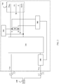
- FIG. 1 is a brief schematic structural diagram of a charger according to some embodiments. As shown in FIG. 1 , the charger includes a switch component 100, a charging circuit 200, a detection signal generation circuit 300, a sampling component 400, a feedback circuit 500, and a charging interface 700.
- the charger includes a switch component 100, a charging circuit 200, a detection signal generation circuit 300, a sampling component 400, a feedback circuit 500, and a charging interface 700.
- the charging interface 700 may be a micro USB interface, that is, a portable version of a Universal Serial Bus 2.0 (USB 2.0) standard.
- the charging interface 700 usually includes a power pin Vbus, a ground pin GND, and two data transmission pins D+ and D-.
- the charging interface 700 may further include another signal cable defined for the Type-C interface.
- the charger may further include a microprocessor (not shown).
- the microprocessor communicates with a charged device through the data transmission pins, to obtain information about a charging status of the charged device, and adjusts a charging current at any time, to cooperatively implement a flash charging function, a fast charging function, and the like.
- the charger further includes a charging plug 600, an alternating current/direct current conversion circuit (not shown), and a voltage conversion circuit (not shown).
- the charging plug 600 of the charger is connected to an external power supply.
- An external alternating current is converted into a direct current after passing through the alternating current/direct current conversion circuit in the charger, and then a voltage is adjusted through the voltage conversion circuit, to form a power input signal.
- the power input signal is input from power input cables Vin+ and Vin- of the charging circuit 200.
- the charging circuit 200 outputs a charging voltage to the power pin Vbus, and the charger outputs the charging voltage from the power pin Vbus.
- two output terminals of the detection signal generation circuit 300 are respectively connected to the data transmission pin (D+ or D-) and the ground pin GND.
- the detection signal generation circuit 300 is configured to send a detection signal through the data transmission pin (D+ or D-).
- the sampling component 400 is connected in series to an output cable of the detection signal generation circuit 300.
- the feedback circuit 500 can collect, from the sampling component 400, level signals in response to the detection signal.
- the detection signal generation circuit 300 sends the detection signal.
- the detection signal generation circuit 300 is a direct current signal generation circuit, and the detection signal that is output by the detection signal generation circuit 300 is a direct current signal.
- a sampled signal is also a direct current signal.
- the detection signal generation circuit 300 is an alternating current signal (AC signal) generation circuit, and may be a square wave signal generation circuit, a half-wave signal generation circuit, or a pulse signal generation circuit.
- AC signal alternating current signal
- the sampling component 400 is connected in series to the output cable of the detection signal generation circuit 300.
- an output terminal of the detection signal generation circuit 300 is connected to the data transmission pin D+, the detection signal generation circuit 300 is configured to output the detection signal through the data transmission pin D+, and the sampling component 400 is connected in series to an output cable that is of the detection signal generation circuit 300 and that is connected to the data transmission pin D+.
- one of the output terminals of the detection signal generation circuit 300 is connected to the data transmission pin D-, and the sampling component 400 is connected in series to an output cable that is of the detection signal generation circuit 300 and that is connected to the data transmission pin D-.
- an output terminal of the detection signal generation circuit 300 is connected to the data transmission pin D+, and the sampling component 400 is connected in series to a connection cable between the detection signal generation circuit 300 and the ground pin GND.
- an output terminal of the detection signal generation circuit 300 may alternatively be connected to the data transmission pin D-, and the sampling component 400 is connected in series to a connection cable between the detection signal generation circuit 300 and the ground pin GND.
- the feedback circuit 500 is connected to the sampling component 400 and the switch component 100, and is configured to: detect level signals on two terminals of the sampling component 400, generate a feedback signal according to the level signals, and transfer the feedback signal to the switch component 100.
- the feedback circuit 500 may be a comparator, an operational amplifier, or an ADC circuit (analog-to-digital conversion circuit).
- FIG. 6 is a structural block diagram of an example of a feedback circuit according to some embodiments.
- Two input terminals of the feedback circuit 500 are respectively connected to the two terminals of the sampling component 400, to detect the level signals on the two terminals A1 and A2 of the sampling component 400, and the feedback circuit 500 generates the feedback signal according to the level signals.
- the sampling component 400 may be a resistor or an inductor.
- the feedback circuit 500 determines whether the detected level signals meet a preset condition (for example, the level signals are greater than the preset threshold). When the level signals meet the preset condition, the feedback circuit generates a first feedback signal and transfers the first feedback signal to the switch component, and the switch component controls, according to the first feedback signal, the charger to stop outputting the charging voltage.
- a preset condition for example, the level signals are greater than the preset threshold.
- the feedback circuit 500 respectively outputs a high-level feedback signal and a low-level feedback signal according to a comparison result.
- the switch component 100 When the feedback circuit 500 outputs the first feedback signal (for example, a low-level signal), the switch component 100 is controlled to directly break an input path of the power input signal of the charging circuit 200 or break a closed circuit of an output cable of the power pin Vbus, to control the charger to stop outputting the charging voltage.
- the feedback circuit 500 outputs the second feedback signal (for example, a high-level signal)
- the switch component 100 is controlled to form an input path of the power input signal of the charging circuit 200 or form a closed circuit of an output cable of the power pin Vbus, so that the charger outputs the charging voltage.
- the second feedback signal is a high-level signal; or if the first feedback signal is a high-level signal, the second feedback signal is a low-level signal. Specifically, this may be adaptively adjusted according to a design requirement.
- the first feedback signal is a low-level signal and the second feedback signal is a high-level signal is used in this embodiment of the present invention.
- FIG. 7 is a structural block diagram of an example of a feedback circuit according to some embodiments.
- the charger further includes a voltage regulation component 502 (for example, a reference voltage source or a voltage division component).
- a voltage regulation component 502 for example, a reference voltage source or a voltage division component.
- One input terminal U2 of the feedback circuit 500 is connected to one terminal of the voltage regulation element 502, and the other terminal of the voltage regulation component 502 is connected to one terminal A2 of the sampling component 400.
- the other input terminal U1 of the feedback circuit 500 is connected to one terminal A1 of the sampling circuit 400.
- An output terminal U0 of the feedback circuit 500 is connected to the switch component 100.
- the voltage regulation component 502 provides an allowed range of a detection error, to avoid erroneous determining caused by an interference voltage.
- a level value of the input terminal U2 that is of the feedback circuit 500 and that is connected to the voltage regulation component 502 is not less than a level value of the other input terminal U1.
- the feedback circuit 500 outputs the second feedback signal (that is, a normal feedback signal, for example, a high-level signal), and the second feedback signal may enable the switch component 100 to connect the charging circuit to the power pin, or form the input path of the power input signal of the charging circuit. That is, the charging circuit 200 generates the charging voltage, and outputs the charging voltage to the power pin.
- an abnormal short circuit occurs on the charging interface, that is, a short circuit occurs between the data transmission pins of the charging interface and a signal ground
- a current passing through the sampling component 400 may abnormally increase, and therefore a level difference between the two terminals A1 and A2 of the sampling component 400 may exceed a preset threshold.
- This change causes a change of a value relationship between voltages on the two input terminals of the feedback circuit 500, that is, a level value on the input terminal U1 is greater than a level value on the other input terminal U2, and therefore the second feedback signal that is output by the output terminal U0 of the feedback circuit 500 may be changed to the first feedback signal (that is, an abnormal feedback signal, for example, a low-level signal).
- the first feedback signal may enable the switch component 100 to break the input path of the power input signal of the charging circuit, that is, the charging circuit cannot generate the charging voltage; or to directly disconnect the charging circuit from the power pin, so that the charger stops outputting the charging voltage. Therefore, short circuit detection and protection is implemented.
- a capacitor C p is added between the terminal A1 of the sampling circuit 400 and the input terminal U1 of the feedback circuit 500, and the capacitor C p has a particular charging time.
- the feedback circuit 500 can output the first feedback signal (that is, the abnormal feedback signal) after a current on the terminal A1 of the sampling circuit 400 has changed for a particular time, so that erroneous detection caused by an interference signal is avoided. Therefore, the charger stops outputting the charging voltage.
- the detection signal that is output by the detection signal generation circuit 300 is an alternating current signal.
- the feedback circuit 500 may detect level signals on the two terminals of the sampling component 400 (for example, a current sensing resistor) for a plurality of times. According to a gradual charging principle of the capacitor C p , only when duration during which the level signals meet the preset condition exceeds a preset time, or level signals obtained through at least N times of consecutive detections all meet the preset condition (a value of N may be adaptively adjusted and customized according to a design requirement), a responsive level value is reached on an input cable terminal of the feedback circuit, and a corresponding feedback signal is generated.
- the feedback circuit 500 when detecting that the duration during which the level signals on the two terminals of the sampling component meet the preset condition exceeds the preset time or that the level signals obtained through the at least N times of consecutive detections all meet the preset condition, the feedback circuit 500 outputs the first feedback signal (that is, the abnormal feedback signal, for example, a low-level signal).
- the first feedback signal that is, the abnormal feedback signal, for example, a low-level signal.
- Level signals on the two terminals of the sampling component 400 are detected for a plurality of times, so that sampling precision can be further improved, and erroneous determining likely to be caused by a single time of determining can be avoided.
- the detection signal that is output by the detection signal generation circuit 300 is the alternating current signal.
- the alternating current signal has low energy, and therefore causes no damage to a cable.
- a current loop is formed among the detection signal generation circuit, the sampling component, the data transmission pins, and the GND pin.
- the level signals on the two terminals of the sampling component are greater than a preset threshold.
- a preset condition is set, and the preset condition may be that the level signals are greater than a preset threshold. Therefore, when the level signals meet the preset condition (that is, the level signals are greater than the preset threshold), the feedback circuit 500 generates the first feedback signal; or when the level signals do not meet the preset condition (that is, the level signals are less than the preset threshold), the feedback circuit 500 generates the second feedback signal.
- the first feedback signal is a high-level signal and the second feedback signal is a low-level signal; or the first feedback signal is a low-level signal and the second feedback signal is a high-level signal.
- the switch component 100 is connected in series to a power input cable of the charging circuit 200 or is connected in series to a connection cable between the charging circuit 200 and the power pin Vbus, and the switch component 100 is configured to: receive the feedback signal, and control, according to the feedback signal, the charger to output the charging voltage.
- a manner in which the switch component 100 controls the charger to stop outputting the charging voltage may include: breaking the input path of the power input signal of the charging circuit 200, to control the charging circuit 200 to stop a charging conversion work; or disconnecting the charging circuit 200 from the power pin Vbus, to stop the charging circuit 200 from outputting the charging voltage output to the power pin Vbus.
- the switch component 100 may be a component that can be used as a switch, such as a transistor or a field effect transistor, and the charging voltage is cut off by directly breaking a signal path.
- the switch component 100 may alternatively be connected in series to the power input cable Vin- of the charging circuit 200.
- the switch component 100 is connected in series to the power input cable Vin+ of the charging circuit 200.
- the switch component 100 breaks the input path of the power input signal of the charging circuit 100 according to the first feedback signal, so that the charging circuit 100 stops generating the charging voltage; or forms the input path of the power input signal of the charging circuit 100 according to the second feedback signal, so that the charging circuit 100 generates the charging voltage and outputs the charging voltage through the power pin Vbus.
- the switch component 100 is connected in series to the connection cable between the charging circuit 200 and the power pin Vbus, and the switch component 100 disconnects the charging circuit 200 from the power pin Vbus according to the first feedback signal, so that the power pin Vbus stops outputting a charging signal; or the switch component 100 connects the charging circuit 200 to the power pin Vbus according to the second feedback signal.
- the sampling component 400 when the switch component 100 is disposed on the power input cable Vin+ of the charging circuit 200, the sampling component 400 is connected in series to an output cable of the detection signal generation circuit 300, and the output cable may be the output cable connected to the data transmission pin D- or the output cable connected to the data transmission pin D+. In some embodiments, when the switch component 100 is disposed on the connection cable between the charging circuit 200 and the power pin Vbus, the sampling component 400 may also be connected in series to an output cable of the detection signal generation circuit 300, and the output cable may be the output cable connected to the data transmission pin D- or the output cable connected to the data transmission pin D+.
- the switch component 100 may alternatively be a PWM circuit, and the PWM circuit is configured to generate a PWM signal.
- the PWM signal is preferably a square wave signal, and the PWM signal can control the charging circuit 200 to generate the charging voltage.
- the PWM circuit outputs the PWM signal according to the second feedback signal, and the charging circuit 200 can normally generate the charging voltage according to the PWM signal, that is, provide the charging voltage to the power pin Vbus.
- the PWM circuit stops outputting the PWM signal or adjusts a duty cycle of the PWM signal to 0 or 100%, so that the charging circuit 200 stops outputting the charging voltage, that is, stops providing the charging voltage to the power pin Vbus.
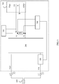
- FIG. 8 is a structural block diagram of an example of the charging circuit 200 according to some embodiments.
- the charging circuit 200 includes a switch element 202 and a transformer 201.
- the switch element 202 is separately connected to the switch component 100, a primary side of the transformer 201, and the power input cable Vin+.
- the switch element 202 periodically controls, according to the PWM signal, the primary side of the transformer 201 to receive an input signal.
- Two output terminals of a secondary side of the transformer are respectively connected to the power pin Vbus and the ground pin GND; and generate the charging voltage according to the input signal received by the primary side of the transformer, and output the charging voltage to the power pin Vbus.
- the power input signal is input from an input terminal of the primary side Np of the transformer, and with periodical turning-on or turning-off of the switch element 202, the secondary side N s of the transformer generates an output signal through sensing.
- the switch component 100 sends the PWM signal to the switch element 202, to control periodical turning-on or turning-off of the switch element 202. If the switch component stops sending a square wave signal, the secondary side N s of the transformer 201 cannot generate an output current through sensing, and therefore the charger stops outputting the charging voltage.
- one terminal of the primary side Np of the transformer 201 is connected to the power input cable Vin+, and the other terminal is connected to the other power input cable Vin- through the main switch transistor.
- One terminal of the secondary side N s of the transformer 201 is connected to the power pin Vbus, and the other terminal is connected to the ground pin GND.
- the switch element 202 is an NMOS transistor, including a gate G, a source S, and a drain D.
- the gate G is connected to the switch component 100, the source S is connected to the power input cable Vin-, and the drain D is connected to the primary side Np of the transformer.
- the switch component 100 sends a control signal to the switch element 202 through the gate G.
- the control signal is a square wave signal.
- the square wave signal is at a high level, the drain D and the gate G of the NMOS transistor are turned on; or when the square wave signal is at a low level, the drain D and the gate G of the NMOS transistor are turned off.
- the charger includes an abnormality protection circuit formed by the switch component 100, the detection signal generation circuit 300, the sampling component 400, and the feedback circuit 500, to avoid a damage to the charger or a charged device that is caused by an abnormal impedance decrease due to entry of water or a foreign matter.
- the detection signal generation circuit 300 may continuously or periodically send detection signals, and the feedback circuit 500 continuously or periodically obtains level signals on the two terminals of the sampling component 400 and sends a feedback signal to the switch component 100.
- Some embodiments provide a method for implementing charging abnormality protection by using the charger described in the foregoing embodiments.
- the method includes the following steps:
- the feedback circuit 500 When the level signals meet a preset condition, the feedback circuit 500 generates a first feedback signal, and the switch component 100 controls, according to the first feedback signal, the charger to stop outputting the charging voltage; or when the level signals do not meet the preset condition, the feedback circuit 500 generates a second feedback signal, and the switch component 100 controls, according to the second feedback signal, the charger to output the charging voltage.
- All or some functions of the detection signal generation circuit, the sampling component, the feedback circuit, the switch component, the charging circuit, the voltage regulation component, and the capacitor in the embodiments of the present invention may be implemented by a processor or a controller chip, or may be implemented by separate components.
- a value relationship between levels, a value relationship between voltages, and a high/low state of a logical level in the embodiments of the present invention are merely an implementation of the embodiments of the present invention, and parameter values may be appropriately adjusted according to a circuit requirement.
- a reference voltage not only may represent a reference voltage source, but also may represent a level value of a reference voltage.
- the value relationship between levels in the embodiments of the present invention is merely an implementation of the embodiments of the present invention, and parameter values may be appropriately adjusted according to a circuit requirement.
- the program may be stored in a computer-readable storage medium.
- the storage medium may include a read-only memory, a magnetic disk, an optical disc, or the like.
Applications Claiming Priority (1)
| Application Number | Priority Date | Filing Date | Title |
|---|---|---|---|
| PCT/CN2016/102196 WO2018068323A1 (zh) | 2016-10-14 | 2016-10-14 | 充电器 |
Publications (3)
| Publication Number | Publication Date |
|---|---|
| EP3522332A1 EP3522332A1 (en) | 2019-08-07 |
| EP3522332A4 EP3522332A4 (en) | 2019-09-25 |
| EP3522332B1 true EP3522332B1 (en) | 2021-12-29 |
Family
ID=61904921
Family Applications (1)
| Application Number | Title | Priority Date | Filing Date |
|---|---|---|---|
| EP16918593.1A Active EP3522332B1 (en) | 2016-10-14 | 2016-10-14 | Charger |
Country Status (4)
| Country | Link |
|---|---|
| US (1) | US10998741B2 (zh) |
| EP (1) | EP3522332B1 (zh) |
| CN (1) | CN109804527B (zh) |
| WO (1) | WO2018068323A1 (zh) |
Families Citing this family (13)
| Publication number | Priority date | Publication date | Assignee | Title |
|---|---|---|---|---|
| CN112803539B (zh) * | 2016-11-15 | 2023-09-08 | 华为技术有限公司 | 一种充电方法及相关设备 |
| WO2020073253A1 (zh) | 2018-10-10 | 2020-04-16 | 华为技术有限公司 | 一种检测浸水的方法、电路及电子设备 |
| CN109560581B (zh) * | 2018-11-13 | 2020-12-01 | Oppo广东移动通信有限公司 | 充电处理方法、充电处理电路、电子设备及存储介质 |
| CN110554240A (zh) * | 2019-09-09 | 2019-12-10 | Oppo(重庆)智能科技有限公司 | 一种充电接口的阻抗检测电路、方法及终端设备 |
| CN110888168B (zh) * | 2019-11-20 | 2022-05-13 | 歌尔科技有限公司 | 充电接口检测电路、智能穿戴设备及充电系统 |
| WO2021213286A1 (zh) * | 2020-04-24 | 2021-10-28 | 深圳市韶音科技有限公司 | 一种充电控制电路及声学输出设备 |
| US11334133B2 (en) * | 2020-04-24 | 2022-05-17 | Dell Products L.P. | Power management of voltage regulators in an information handling system |
| CN112070974B (zh) * | 2020-08-05 | 2022-05-06 | 深圳来电科技有限公司 | 一种自动排查充电宝异常情况的方法、装置、计算机设备及计算机可读介质 |
| CN112290610B (zh) * | 2020-08-25 | 2022-08-16 | 歌尔科技有限公司 | 充电控制电路及充电控制方法 |
| CN112701750A (zh) * | 2020-12-21 | 2021-04-23 | 维沃移动通信有限公司 | 接头、电子设备及其控制方法、装置 |
| CN114710738B (zh) * | 2022-03-31 | 2023-03-24 | 深圳市微源半导体股份有限公司 | 一种基于通信方式的tws耳机的汗液检测方法 |
| CN116087825B (zh) * | 2022-12-05 | 2023-09-29 | 江苏帝奥微电子股份有限公司 | 一种充电接口异物短路检测芯片、检测装置及方法 |
| CN116599195B (zh) * | 2023-07-14 | 2023-10-27 | 东莞市奥海科技股份有限公司 | 含有存储功能的充电电路及充电器 |
Family Cites Families (8)
| Publication number | Priority date | Publication date | Assignee | Title |
|---|---|---|---|---|
| US8143862B2 (en) | 2009-03-12 | 2012-03-27 | 02Micro Inc. | Circuits and methods for battery charging |
| CN101945534B (zh) * | 2010-09-01 | 2012-12-19 | 惠州Tcl移动通信有限公司 | 移动终端进水后电路板的保护方法及电路及一种移动终端 |
| JP6099894B2 (ja) | 2012-07-11 | 2017-03-22 | セミコンダクター・コンポーネンツ・インダストリーズ・リミテッド・ライアビリティ・カンパニー | 携帯電子機器の充電システム |
| CN103532187B (zh) * | 2013-09-29 | 2015-11-25 | 小米科技有限责任公司 | 充电器、充电线、充电系统及充电方法 |
| BR112017011439B1 (pt) * | 2014-12-31 | 2022-05-03 | Huawei Technologies Co., Ltd | Método e aparelho de proteção de carga |
| WO2016153576A1 (en) | 2015-03-20 | 2016-09-29 | Dialog Semiconductor Inc. | Soft-short overvoltage protection for data lines in quick charge usb charger |
| CN104767260B (zh) | 2015-03-30 | 2017-04-05 | 华为技术有限公司 | 充电器、终端设备和充电系统 |
| CN205610274U (zh) * | 2016-04-29 | 2016-09-28 | 维沃移动通信有限公司 | 一种充电短路保护电路及电子设备 |
-
2016
- 2016-10-14 CN CN201680090005.5A patent/CN109804527B/zh active Active
- 2016-10-14 EP EP16918593.1A patent/EP3522332B1/en active Active
- 2016-10-14 WO PCT/CN2016/102196 patent/WO2018068323A1/zh unknown
- 2016-10-14 US US16/341,712 patent/US10998741B2/en active Active
Non-Patent Citations (1)
| Title |
|---|
| None * |
Also Published As
| Publication number | Publication date |
|---|---|
| US20200052510A1 (en) | 2020-02-13 |
| CN109804527B (zh) | 2021-06-15 |
| US10998741B2 (en) | 2021-05-04 |
| EP3522332A1 (en) | 2019-08-07 |
| EP3522332A4 (en) | 2019-09-25 |
| CN109804527A (zh) | 2019-05-24 |
| WO2018068323A1 (zh) | 2018-04-19 |
Similar Documents
| Publication | Publication Date | Title |
|---|---|---|
| EP3522332B1 (en) | Charger | |
| US10601242B2 (en) | Micro short protection for charger, terminal device, and charging system | |
| US10461549B2 (en) | Mobile terminal, DC-charging power source adaptor, and charging method | |
| US10050460B2 (en) | Mobile terminal, DC-charging power source adaptor, and charging method | |
| EP3282550B1 (en) | Adapter and charging control method | |
| US10050466B2 (en) | DC-charging power source adaptor and mobile terminal | |
| US9479060B2 (en) | Control circuit, battery power supply device and control method | |
| US11946979B2 (en) | Short circuit and soft short protection for data interface charging | |
| JP5451094B2 (ja) | 充電回路、充電装置、電子機器及び充電方法 | |
| CN107431351B (zh) | 对快充usb充电器中的数据线的软短路过电压保护 | |
| US20160111892A1 (en) | Front-end circuits for wireless power receivers, wireless chargers and wireless charging | |
| US9584041B2 (en) | Method and apparatus for charging devices using a multiple port power supply | |
| CN213185645U (zh) | 无线电力接收电路和电子设备 | |
| EP2228884A2 (en) | Circuits and methods for battery charging | |
| US10199818B2 (en) | System and method for wireless power transfer using over-voltage protection | |
| US20080174277A1 (en) | Charging apparatus | |
| EP4207552A1 (en) | Fast charging method and system, terminal, and charger | |
| US20130049680A1 (en) | Electronic device | |
| US10116351B2 (en) | Pollution detection circuit for data lines and method thereof | |
| JP6553346B2 (ja) | 過電流検出回路およびそれを利用したusb給電装置、電子機器、過電流検出方法 | |
| WO2017099768A1 (en) | Short circuit protection for data interface charging | |
| KR20110022136A (ko) | 입력전압 검출회로 |
Legal Events
| Date | Code | Title | Description |
|---|---|---|---|
| STAA | Information on the status of an ep patent application or granted ep patent |
Free format text: STATUS: THE INTERNATIONAL PUBLICATION HAS BEEN MADE |
|
| PUAI | Public reference made under article 153(3) epc to a published international application that has entered the european phase |
Free format text: ORIGINAL CODE: 0009012 |
|
| STAA | Information on the status of an ep patent application or granted ep patent |
Free format text: STATUS: REQUEST FOR EXAMINATION WAS MADE |
|
| 17P | Request for examination filed |
Effective date: 20190430 |
|
| AK | Designated contracting states |
Kind code of ref document: A1 Designated state(s): AL AT BE BG CH CY CZ DE DK EE ES FI FR GB GR HR HU IE IS IT LI LT LU LV MC MK MT NL NO PL PT RO RS SE SI SK SM TR |
|
| AX | Request for extension of the european patent |
Extension state: BA ME |
|
| A4 | Supplementary search report drawn up and despatched |
Effective date: 20190822 |
|
| RIC1 | Information provided on ipc code assigned before grant |
Ipc: H02J 7/04 20060101AFI20190816BHEP Ipc: H02J 7/02 20160101ALI20190816BHEP Ipc: H02J 7/00 20060101ALI20190816BHEP |
|
| DAV | Request for validation of the european patent (deleted) | ||
| DAX | Request for extension of the european patent (deleted) | ||
| STAA | Information on the status of an ep patent application or granted ep patent |
Free format text: STATUS: EXAMINATION IS IN PROGRESS |
|
| 17Q | First examination report despatched |
Effective date: 20200625 |
|
| STAA | Information on the status of an ep patent application or granted ep patent |
Free format text: STATUS: EXAMINATION IS IN PROGRESS |
|
| GRAP | Despatch of communication of intention to grant a patent |
Free format text: ORIGINAL CODE: EPIDOSNIGR1 |
|
| STAA | Information on the status of an ep patent application or granted ep patent |
Free format text: STATUS: GRANT OF PATENT IS INTENDED |
|
| INTG | Intention to grant announced |
Effective date: 20210719 |
|
| GRAS | Grant fee paid |
Free format text: ORIGINAL CODE: EPIDOSNIGR3 |
|
| GRAA | (expected) grant |
Free format text: ORIGINAL CODE: 0009210 |
|
| STAA | Information on the status of an ep patent application or granted ep patent |
Free format text: STATUS: THE PATENT HAS BEEN GRANTED |
|
| AK | Designated contracting states |
Kind code of ref document: B1 Designated state(s): AL AT BE BG CH CY CZ DE DK EE ES FI FR GB GR HR HU IE IS IT LI LT LU LV MC MK MT NL NO PL PT RO RS SE SI SK SM TR |
|
| REG | Reference to a national code |
Ref country code: GB Ref legal event code: FG4D |
|
| REG | Reference to a national code |
Ref country code: CH Ref legal event code: EP |
|
| REG | Reference to a national code |
Ref country code: AT Ref legal event code: REF Ref document number: 1459404 Country of ref document: AT Kind code of ref document: T Effective date: 20220115 |
|
| REG | Reference to a national code |
Ref country code: IE Ref legal event code: FG4D |
|
| REG | Reference to a national code |
Ref country code: DE Ref legal event code: R096 Ref document number: 602016067980 Country of ref document: DE |
|
| REG | Reference to a national code |
Ref country code: LT Ref legal event code: MG9D |
|
| PG25 | Lapsed in a contracting state [announced via postgrant information from national office to epo] |
Ref country code: RS Free format text: LAPSE BECAUSE OF FAILURE TO SUBMIT A TRANSLATION OF THE DESCRIPTION OR TO PAY THE FEE WITHIN THE PRESCRIBED TIME-LIMIT Effective date: 20211229 Ref country code: LT Free format text: LAPSE BECAUSE OF FAILURE TO SUBMIT A TRANSLATION OF THE DESCRIPTION OR TO PAY THE FEE WITHIN THE PRESCRIBED TIME-LIMIT Effective date: 20211229 Ref country code: FI Free format text: LAPSE BECAUSE OF FAILURE TO SUBMIT A TRANSLATION OF THE DESCRIPTION OR TO PAY THE FEE WITHIN THE PRESCRIBED TIME-LIMIT Effective date: 20211229 Ref country code: BG Free format text: LAPSE BECAUSE OF FAILURE TO SUBMIT A TRANSLATION OF THE DESCRIPTION OR TO PAY THE FEE WITHIN THE PRESCRIBED TIME-LIMIT Effective date: 20220329 |
|
| REG | Reference to a national code |
Ref country code: NL Ref legal event code: MP Effective date: 20211229 |
|
| REG | Reference to a national code |
Ref country code: AT Ref legal event code: MK05 Ref document number: 1459404 Country of ref document: AT Kind code of ref document: T Effective date: 20211229 |
|
| PG25 | Lapsed in a contracting state [announced via postgrant information from national office to epo] |
Ref country code: SE Free format text: LAPSE BECAUSE OF FAILURE TO SUBMIT A TRANSLATION OF THE DESCRIPTION OR TO PAY THE FEE WITHIN THE PRESCRIBED TIME-LIMIT Effective date: 20211229 Ref country code: NO Free format text: LAPSE BECAUSE OF FAILURE TO SUBMIT A TRANSLATION OF THE DESCRIPTION OR TO PAY THE FEE WITHIN THE PRESCRIBED TIME-LIMIT Effective date: 20220329 Ref country code: LV Free format text: LAPSE BECAUSE OF FAILURE TO SUBMIT A TRANSLATION OF THE DESCRIPTION OR TO PAY THE FEE WITHIN THE PRESCRIBED TIME-LIMIT Effective date: 20211229 Ref country code: HR Free format text: LAPSE BECAUSE OF FAILURE TO SUBMIT A TRANSLATION OF THE DESCRIPTION OR TO PAY THE FEE WITHIN THE PRESCRIBED TIME-LIMIT Effective date: 20211229 Ref country code: GR Free format text: LAPSE BECAUSE OF FAILURE TO SUBMIT A TRANSLATION OF THE DESCRIPTION OR TO PAY THE FEE WITHIN THE PRESCRIBED TIME-LIMIT Effective date: 20220330 |
|
| PG25 | Lapsed in a contracting state [announced via postgrant information from national office to epo] |
Ref country code: NL Free format text: LAPSE BECAUSE OF FAILURE TO SUBMIT A TRANSLATION OF THE DESCRIPTION OR TO PAY THE FEE WITHIN THE PRESCRIBED TIME-LIMIT Effective date: 20211229 |
|
| PG25 | Lapsed in a contracting state [announced via postgrant information from national office to epo] |
Ref country code: SM Free format text: LAPSE BECAUSE OF FAILURE TO SUBMIT A TRANSLATION OF THE DESCRIPTION OR TO PAY THE FEE WITHIN THE PRESCRIBED TIME-LIMIT Effective date: 20211229 Ref country code: SK Free format text: LAPSE BECAUSE OF FAILURE TO SUBMIT A TRANSLATION OF THE DESCRIPTION OR TO PAY THE FEE WITHIN THE PRESCRIBED TIME-LIMIT Effective date: 20211229 Ref country code: RO Free format text: LAPSE BECAUSE OF FAILURE TO SUBMIT A TRANSLATION OF THE DESCRIPTION OR TO PAY THE FEE WITHIN THE PRESCRIBED TIME-LIMIT Effective date: 20211229 Ref country code: PT Free format text: LAPSE BECAUSE OF FAILURE TO SUBMIT A TRANSLATION OF THE DESCRIPTION OR TO PAY THE FEE WITHIN THE PRESCRIBED TIME-LIMIT Effective date: 20220429 Ref country code: ES Free format text: LAPSE BECAUSE OF FAILURE TO SUBMIT A TRANSLATION OF THE DESCRIPTION OR TO PAY THE FEE WITHIN THE PRESCRIBED TIME-LIMIT Effective date: 20211229 Ref country code: EE Free format text: LAPSE BECAUSE OF FAILURE TO SUBMIT A TRANSLATION OF THE DESCRIPTION OR TO PAY THE FEE WITHIN THE PRESCRIBED TIME-LIMIT Effective date: 20211229 Ref country code: CZ Free format text: LAPSE BECAUSE OF FAILURE TO SUBMIT A TRANSLATION OF THE DESCRIPTION OR TO PAY THE FEE WITHIN THE PRESCRIBED TIME-LIMIT Effective date: 20211229 |
|
| PG25 | Lapsed in a contracting state [announced via postgrant information from national office to epo] |
Ref country code: PL Free format text: LAPSE BECAUSE OF FAILURE TO SUBMIT A TRANSLATION OF THE DESCRIPTION OR TO PAY THE FEE WITHIN THE PRESCRIBED TIME-LIMIT Effective date: 20211229 Ref country code: AT Free format text: LAPSE BECAUSE OF FAILURE TO SUBMIT A TRANSLATION OF THE DESCRIPTION OR TO PAY THE FEE WITHIN THE PRESCRIBED TIME-LIMIT Effective date: 20211229 |
|
| PG25 | Lapsed in a contracting state [announced via postgrant information from national office to epo] |
Ref country code: IS Free format text: LAPSE BECAUSE OF FAILURE TO SUBMIT A TRANSLATION OF THE DESCRIPTION OR TO PAY THE FEE WITHIN THE PRESCRIBED TIME-LIMIT Effective date: 20220429 |
|
| REG | Reference to a national code |
Ref country code: DE Ref legal event code: R097 Ref document number: 602016067980 Country of ref document: DE |
|
| PG25 | Lapsed in a contracting state [announced via postgrant information from national office to epo] |
Ref country code: DK Free format text: LAPSE BECAUSE OF FAILURE TO SUBMIT A TRANSLATION OF THE DESCRIPTION OR TO PAY THE FEE WITHIN THE PRESCRIBED TIME-LIMIT Effective date: 20211229 Ref country code: AL Free format text: LAPSE BECAUSE OF FAILURE TO SUBMIT A TRANSLATION OF THE DESCRIPTION OR TO PAY THE FEE WITHIN THE PRESCRIBED TIME-LIMIT Effective date: 20211229 |
|
| PLBE | No opposition filed within time limit |
Free format text: ORIGINAL CODE: 0009261 |
|
| STAA | Information on the status of an ep patent application or granted ep patent |
Free format text: STATUS: NO OPPOSITION FILED WITHIN TIME LIMIT |
|
| 26N | No opposition filed |
Effective date: 20220930 |
|
| PG25 | Lapsed in a contracting state [announced via postgrant information from national office to epo] |
Ref country code: SI Free format text: LAPSE BECAUSE OF FAILURE TO SUBMIT A TRANSLATION OF THE DESCRIPTION OR TO PAY THE FEE WITHIN THE PRESCRIBED TIME-LIMIT Effective date: 20211229 |
|
| PG25 | Lapsed in a contracting state [announced via postgrant information from national office to epo] |
Ref country code: MC Free format text: LAPSE BECAUSE OF FAILURE TO SUBMIT A TRANSLATION OF THE DESCRIPTION OR TO PAY THE FEE WITHIN THE PRESCRIBED TIME-LIMIT Effective date: 20211229 Ref country code: IT Free format text: LAPSE BECAUSE OF FAILURE TO SUBMIT A TRANSLATION OF THE DESCRIPTION OR TO PAY THE FEE WITHIN THE PRESCRIBED TIME-LIMIT Effective date: 20211229 |
|
| REG | Reference to a national code |
Ref country code: CH Ref legal event code: PL |
|
| REG | Reference to a national code |
Ref country code: BE Ref legal event code: MM Effective date: 20221031 |
|
| PG25 | Lapsed in a contracting state [announced via postgrant information from national office to epo] |
Ref country code: LU Free format text: LAPSE BECAUSE OF NON-PAYMENT OF DUE FEES Effective date: 20221014 |
|
| PG25 | Lapsed in a contracting state [announced via postgrant information from national office to epo] |
Ref country code: LI Free format text: LAPSE BECAUSE OF NON-PAYMENT OF DUE FEES Effective date: 20221031 Ref country code: CH Free format text: LAPSE BECAUSE OF NON-PAYMENT OF DUE FEES Effective date: 20221031 |
|
| PG25 | Lapsed in a contracting state [announced via postgrant information from national office to epo] |
Ref country code: BE Free format text: LAPSE BECAUSE OF NON-PAYMENT OF DUE FEES Effective date: 20221031 |
|
| PG25 | Lapsed in a contracting state [announced via postgrant information from national office to epo] |
Ref country code: IE Free format text: LAPSE BECAUSE OF NON-PAYMENT OF DUE FEES Effective date: 20221014 |
|
| PGFP | Annual fee paid to national office [announced via postgrant information from national office to epo] |
Ref country code: GB Payment date: 20230831 Year of fee payment: 8 |
|
| PGFP | Annual fee paid to national office [announced via postgrant information from national office to epo] |
Ref country code: FR Payment date: 20230911 Year of fee payment: 8 |
|
| PGFP | Annual fee paid to national office [announced via postgrant information from national office to epo] |
Ref country code: DE Payment date: 20230830 Year of fee payment: 8 |
|
| PG25 | Lapsed in a contracting state [announced via postgrant information from national office to epo] |
Ref country code: HU Free format text: LAPSE BECAUSE OF FAILURE TO SUBMIT A TRANSLATION OF THE DESCRIPTION OR TO PAY THE FEE WITHIN THE PRESCRIBED TIME-LIMIT; INVALID AB INITIO Effective date: 20161014 |