EP3522262B1 - Batteriezelle mit überladeschutzelement - Google Patents
Batteriezelle mit überladeschutzelement Download PDFInfo
- Publication number
- EP3522262B1 EP3522262B1 EP18824555.9A EP18824555A EP3522262B1 EP 3522262 B1 EP3522262 B1 EP 3522262B1 EP 18824555 A EP18824555 A EP 18824555A EP 3522262 B1 EP3522262 B1 EP 3522262B1
- Authority
- EP
- European Patent Office
- Prior art keywords
- exterior material
- cell
- cutter part
- electrode assembly
- cutter
- Prior art date
- Legal status (The legal status is an assumption and is not a legal conclusion. Google has not performed a legal analysis and makes no representation as to the accuracy of the status listed.)
- Active
Links
Images




Classifications
-
- H—ELECTRICITY
- H01—ELECTRIC ELEMENTS
- H01M—PROCESSES OR MEANS, e.g. BATTERIES, FOR THE DIRECT CONVERSION OF CHEMICAL ENERGY INTO ELECTRICAL ENERGY
- H01M50/00—Constructional details or processes of manufacture of the non-active parts of electrochemical cells other than fuel cells, e.g. hybrid cells
- H01M50/50—Current conducting connections for cells or batteries
- H01M50/572—Means for preventing undesired use or discharge
- H01M50/574—Devices or arrangements for the interruption of current
- H01M50/578—Devices or arrangements for the interruption of current in response to pressure
-
- H—ELECTRICITY
- H01—ELECTRIC ELEMENTS
- H01M—PROCESSES OR MEANS, e.g. BATTERIES, FOR THE DIRECT CONVERSION OF CHEMICAL ENERGY INTO ELECTRICAL ENERGY
- H01M50/00—Constructional details or processes of manufacture of the non-active parts of electrochemical cells other than fuel cells, e.g. hybrid cells
- H01M50/10—Primary casings; Jackets or wrappings
- H01M50/102—Primary casings; Jackets or wrappings characterised by their shape or physical structure
- H01M50/105—Pouches or flexible bags
-
- H—ELECTRICITY
- H01—ELECTRIC ELEMENTS
- H01M—PROCESSES OR MEANS, e.g. BATTERIES, FOR THE DIRECT CONVERSION OF CHEMICAL ENERGY INTO ELECTRICAL ENERGY
- H01M50/00—Constructional details or processes of manufacture of the non-active parts of electrochemical cells other than fuel cells, e.g. hybrid cells
- H01M50/10—Primary casings; Jackets or wrappings
- H01M50/116—Primary casings; Jackets or wrappings characterised by the material
- H01M50/117—Inorganic material
- H01M50/119—Metals
-
- H—ELECTRICITY
- H01—ELECTRIC ELEMENTS
- H01M—PROCESSES OR MEANS, e.g. BATTERIES, FOR THE DIRECT CONVERSION OF CHEMICAL ENERGY INTO ELECTRICAL ENERGY
- H01M50/00—Constructional details or processes of manufacture of the non-active parts of electrochemical cells other than fuel cells, e.g. hybrid cells
- H01M50/10—Primary casings; Jackets or wrappings
- H01M50/172—Arrangements of electric connectors penetrating the casing
- H01M50/174—Arrangements of electric connectors penetrating the casing adapted for the shape of the cells
- H01M50/178—Arrangements of electric connectors penetrating the casing adapted for the shape of the cells for pouch or flexible bag cells
-
- H—ELECTRICITY
- H01—ELECTRIC ELEMENTS
- H01M—PROCESSES OR MEANS, e.g. BATTERIES, FOR THE DIRECT CONVERSION OF CHEMICAL ENERGY INTO ELECTRICAL ENERGY
- H01M50/00—Constructional details or processes of manufacture of the non-active parts of electrochemical cells other than fuel cells, e.g. hybrid cells
- H01M50/30—Arrangements for facilitating escape of gases
-
- H—ELECTRICITY
- H01—ELECTRIC ELEMENTS
- H01M—PROCESSES OR MEANS, e.g. BATTERIES, FOR THE DIRECT CONVERSION OF CHEMICAL ENERGY INTO ELECTRICAL ENERGY
- H01M50/00—Constructional details or processes of manufacture of the non-active parts of electrochemical cells other than fuel cells, e.g. hybrid cells
- H01M50/30—Arrangements for facilitating escape of gases
- H01M50/342—Non-re-sealable arrangements
- H01M50/3425—Non-re-sealable arrangements in the form of rupturable membranes or weakened parts, e.g. pierced with the aid of a sharp member
-
- H—ELECTRICITY
- H01—ELECTRIC ELEMENTS
- H01M—PROCESSES OR MEANS, e.g. BATTERIES, FOR THE DIRECT CONVERSION OF CHEMICAL ENERGY INTO ELECTRICAL ENERGY
- H01M50/00—Constructional details or processes of manufacture of the non-active parts of electrochemical cells other than fuel cells, e.g. hybrid cells
- H01M50/50—Current conducting connections for cells or batteries
- H01M50/543—Terminals
- H01M50/547—Terminals characterised by the disposition of the terminals on the cells
- H01M50/548—Terminals characterised by the disposition of the terminals on the cells on opposite sides of the cell
-
- H—ELECTRICITY
- H01—ELECTRIC ELEMENTS
- H01M—PROCESSES OR MEANS, e.g. BATTERIES, FOR THE DIRECT CONVERSION OF CHEMICAL ENERGY INTO ELECTRICAL ENERGY
- H01M50/00—Constructional details or processes of manufacture of the non-active parts of electrochemical cells other than fuel cells, e.g. hybrid cells
- H01M50/50—Current conducting connections for cells or batteries
- H01M50/543—Terminals
- H01M50/552—Terminals characterised by their shape
- H01M50/553—Terminals adapted for prismatic, pouch or rectangular cells
-
- H—ELECTRICITY
- H01—ELECTRIC ELEMENTS
- H01M—PROCESSES OR MEANS, e.g. BATTERIES, FOR THE DIRECT CONVERSION OF CHEMICAL ENERGY INTO ELECTRICAL ENERGY
- H01M50/00—Constructional details or processes of manufacture of the non-active parts of electrochemical cells other than fuel cells, e.g. hybrid cells
- H01M50/50—Current conducting connections for cells or batteries
- H01M50/572—Means for preventing undesired use or discharge
- H01M50/574—Devices or arrangements for the interruption of current
- H01M50/583—Devices or arrangements for the interruption of current in response to current, e.g. fuses
-
- H—ELECTRICITY
- H01—ELECTRIC ELEMENTS
- H01M—PROCESSES OR MEANS, e.g. BATTERIES, FOR THE DIRECT CONVERSION OF CHEMICAL ENERGY INTO ELECTRICAL ENERGY
- H01M2200/00—Safety devices for primary or secondary batteries
- H01M2200/20—Pressure-sensitive devices
-
- H—ELECTRICITY
- H01—ELECTRIC ELEMENTS
- H01M—PROCESSES OR MEANS, e.g. BATTERIES, FOR THE DIRECT CONVERSION OF CHEMICAL ENERGY INTO ELECTRICAL ENERGY
- H01M50/00—Constructional details or processes of manufacture of the non-active parts of electrochemical cells other than fuel cells, e.g. hybrid cells
- H01M50/10—Primary casings; Jackets or wrappings
- H01M50/116—Primary casings; Jackets or wrappings characterised by the material
- H01M50/121—Organic material
-
- H—ELECTRICITY
- H01—ELECTRIC ELEMENTS
- H01M—PROCESSES OR MEANS, e.g. BATTERIES, FOR THE DIRECT CONVERSION OF CHEMICAL ENERGY INTO ELECTRICAL ENERGY
- H01M50/00—Constructional details or processes of manufacture of the non-active parts of electrochemical cells other than fuel cells, e.g. hybrid cells
- H01M50/10—Primary casings; Jackets or wrappings
- H01M50/116—Primary casings; Jackets or wrappings characterised by the material
- H01M50/124—Primary casings; Jackets or wrappings characterised by the material having a layered structure
-
- Y—GENERAL TAGGING OF NEW TECHNOLOGICAL DEVELOPMENTS; GENERAL TAGGING OF CROSS-SECTIONAL TECHNOLOGIES SPANNING OVER SEVERAL SECTIONS OF THE IPC; TECHNICAL SUBJECTS COVERED BY FORMER USPC CROSS-REFERENCE ART COLLECTIONS [XRACs] AND DIGESTS
- Y02—TECHNOLOGIES OR APPLICATIONS FOR MITIGATION OR ADAPTATION AGAINST CLIMATE CHANGE
- Y02E—REDUCTION OF GREENHOUSE GAS [GHG] EMISSIONS, RELATED TO ENERGY GENERATION, TRANSMISSION OR DISTRIBUTION
- Y02E60/00—Enabling technologies; Technologies with a potential or indirect contribution to GHG emissions mitigation
- Y02E60/10—Energy storage using batteries
-
- Y—GENERAL TAGGING OF NEW TECHNOLOGICAL DEVELOPMENTS; GENERAL TAGGING OF CROSS-SECTIONAL TECHNOLOGIES SPANNING OVER SEVERAL SECTIONS OF THE IPC; TECHNICAL SUBJECTS COVERED BY FORMER USPC CROSS-REFERENCE ART COLLECTIONS [XRACs] AND DIGESTS
- Y02—TECHNOLOGIES OR APPLICATIONS FOR MITIGATION OR ADAPTATION AGAINST CLIMATE CHANGE
- Y02P—CLIMATE CHANGE MITIGATION TECHNOLOGIES IN THE PRODUCTION OR PROCESSING OF GOODS
- Y02P70/00—Climate change mitigation technologies in the production process for final industrial or consumer products
- Y02P70/50—Manufacturing or production processes characterised by the final manufactured product
Definitions
- the present invention relates to a battery cell having an overcharge prevention member, and more particularly, to a battery cell including a protective member for preventing explosion due to the pressure caused by various factors inside the battery.
- the pouch-type lithium secondary battery as a unit cell constituting a battery, has flexibility, a relatively free shape, a light weight, and excellent safety, and thus has increasing demand as a power source for mobile electronic apparatuses, such as smart phones, camcorders, and laptop computers.
- the shape of the secondary battery is classified according to the shape of a battery case.
- the secondary battery is classified into a cylindrical battery or a rectangular battery, and when the electrode assembly is embedded in a pouch-type case of an aluminum laminate sheet, the secondary battery is classified into a pouch-type battery.
- an electrode assembly embedded in a battery case has a structure configured from a positive electrode, a negative electrode, and a separator inserted between the positive electrode and the negative electrode, and thus allows charge/discharge to be performed.
- the shape of the electrode assembly is classified into: a jelly-roll type in which a positive electrode, a negative electrode, and a separator which have elongated sheet shapes and on which an electrode active material is applied, are sequentially stacked and wound; and a stack type electrode assembly in which a plurality of number of positive electrodes, negative electrodes, and separators, which have predetermined sizes and on which an electrode active material is applied, are sequentially stacked.
- the swelling phenomenon increases the volume of the pouch exterior material and weakens the adhesion of a sealing region of the pouch exterior material, so that an electrolyte leaks through the ceiling region of the pouch exterior material, or the inside of the pouch exterior material is brought into a high-temperature and high-pressure atmosphere due to an accelerated side reaction of the electrolyte, thereby burning or exploding the battery cell.
- a battery cell including an explosion prevention member is provided, and a typical battery cell will be described with reference to FIG. 1 .
- FIG.1 is a detailed structural view of a battery cell including a typical explosion preventions member.
- a typical battery cell has a structure which includes an electrode assembly and a lead part having a groove, so that when a swelling phenomenon occurs, a groove-constituting part is destroyed and the coupling of the battery cell is thereby released.
- the present invention provides a battery cell which prevents explosion caused by a pressure generated therein without affecting the output thereof.
- a battery cell includes: an electrode assembly; a cell exterior material configured to accommodate the electrode assembly and including an upper exterior material and a lower exterior material; a lead part extending between the upper exterior material and the lower exterior material from the electrode assembly and led out of the cell exterior material; and a cutting part positioned on upper and lower ends of the lead part and configured to cut and disconnect the lead part when an overcharge occurs.
- the cutting part (140) includes: a first cutter part (141) positioned in the direction toward the electrode assembly, and including a frame attached to the upper exterior material, and accommodating a first cutting blade; a second cutter part (142) positioned on the side of the first cutter part in the direction opposite the electrode assembly, and including a frame attached to the lower exterior material, and accommodating asecond cutting blade; and a third cutter part (143) positioned on the side of the second cutter part in the direction opposite the electrode assembly, and including a frame attached to the upper exterior material, and accommodating a third cutting blade , wherein when an overcharge occurs, the battery cell may expand and a distance between the upper exterior material and the lower exterior material may increase, and the lead part may accordingly cut.
- the first cutting blade of the first cutter part and the third cutting blade of the third cutter part are respectively provided on lower end portions of the frames of the first cutter part and the third cutter part, and be positioned on a lower portion of the lead part when the cutter part is configured.
- the second cutting blade of the second cutter part is formed on an upper end portion of the second cutter part and positioned on an upper portion of the lead part when the cutting part is configured.
- the cutting blades of the first cutter part, the second cutter part, and the third cutter part may be respectively provided in shapes obliquely inclined from one side to the other side.
- portions, in which the first, second and third blades meet, form a predetermined accommodating space.
- a method for manufacturing the battery cell as outlined above includes: an electrode assembly preparation process in which an electrode assembly is prepared through an electrode process; a cell exterior material formation process in which the electrode assembly prepared in the electrode assembly preparation process is accommodated in a cell exterior material having the cutting part; and a cell assembly completing process in which an electrolyte is injected into the cell exterior material formed in the cell exterior material formation process, and the cell exterior material is sealed.
- the cell exterior material formation process may include: a cutting part attachment process in which the first cutter part, the second cutter part, and the third cutter part are attached to the cell exterior material; a position adjustment process in which positions of the first cutter part, the second cutter part, and the third cutter part, which are attached in the cutting part attachment process, are adjusted; and a lead part positioning process in which the lead part connected to the electrode assembly is positioned in an accommodating space generated by adjusting positions in the position adjustment process.
- a battery cell having an overcharge prevention member in accordance with exemplary embodiments is provided with a cutting part, which cuts and disconnects a lead part, and is thereby capable of simply performing a battery cell protection without an additional control, and the battery cell is provided separate from the lead part, and thus, the function of the lead part is not affected.
- first and second are used herein to describe various elements, these elements should not be limited by these terms. The terms are only used to distinguish one component from other components. For example, without departing from the scope of the present invention, a first component may be referred to as a second component, and similarly, the second component may also be referred to as the first component.
- the technical terms are used only for explaining a specific exemplary embodiment while not limiting the present invention. The terms of a singular form may include plural forms unless referred to the contrary.
- a cutting part for cutting and disconnecting a lead part the battery cell is provided to the battery cell in accordance with an exemplary embodiment, and thus, explosion of the battery cell may simply be prevented without a complicated operational configuration.
- FIG. 2 is a structural view of an upper surface of a battery cell in accordance with an exemplary embodiment.
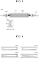
- FIG. 3 is a structural view of a side surface of a battery cell in accordance with an exemplary embodiment.
- a battery cell 100 in accordance with an exemplary embodiment includes: an electrode assembly 110; a cell exterior material 120 accommodating the electrode assembly 110 and configured from an upper exterior material and a lower exterior material; a lead part 130 extending between the upper exterior material and the lower exterior material from the electrode assembly 110 and led out of the cell exterior material 120; and a cutting part 140 positioned on upper and lower ends of the lead part 130 and cuts and disconnects the lead part when an overcharge occurs.
- the battery cell is configured to include an electrolyte, and the electrolyte contacts the electrode assembly during repeated charge/discharge of the battery cell and serves as a medium for transferring lithium ions to a negative electrode or the positive electrode of the electrode assembly.
- the electrode assembly 110 has a structure configured from the positive electrode, the negative electrode, and a separator inserted between the positive electrode and the negative electrode, and may be prepared in a jelly-roll type in which a positive electrode, a separator, and a negative electrode which have elongated sheet shapes and on which electrode active material is applied are sequentially stacked and wound, and a stack type in which a plurality of positive electrodes, separators, and negative electrodes which have predetermined sizes and on which electrode active material is applied are sequentially stacked.
- the negative electrode active material is composed of carbon-based compounds and the positive electrode active material is composed of lithium-based metal compounds.
- the cell exterior material 120 is configured from a metal thin layer and a polymer thin layer sandwiching the metal thin layer, is provided as an upper exterior material and a lower exterior material, accommodates the battery assembly 110 and an electrolyte, and sealed by a thermal fusion with a sealing member through a peripheral sealing region.
- the sealing member surrounds and fuses the lead part 130 in the sealing region of the cell exterior material crossing the lead part 130 and thus improves the sealing characteristic of a pouch exterior material.
- an attachment part having a predetermined width may be provided in the cell exterior material 120 so that the cutting part 140 may be positioned. This allows the cutting part 140 to be guaranteed to have a predetermined space.
- the lead part 130 is a component extending between the upper exterior material and the lower exterior material from the electrode assembly 110 and is led out of the cell exterior material 120, and is configured from a tap 131 of the electrode assembly, a sealing member 132, and a battery cell lead 133.
- the tap 131 of the electrode assembly is a component which is connected to the electrode assembly inside the electrode assembly 110, is configured as one tap when the configuration of the electrode assembly is the jelly-roll type, and is as a single form by overlapping a plurality of taps when the configuration of the electrode assembly is the stack type.
- the sealing member 132 is configured from a lower film and an upper film which are composed of a resin composition, such as polyolefin or modified polyolefin, having a thermal fusion property.
- the sealing member 132 surrounds a battery cell lead 133 by means of the upper film and the lower film, or jointed to the battery cell lead through an adhesive or thermal fusion.
- the battery cell lead 133 is composed of metallic material, and the two battery cell leads are positioned in one direction or in both directions from the electrode assembly 110 and provide an electrical path for charge/discharge current.
- the battery cell leads 133 are allowed to be jointed and electrically connected to taps 131 of the electrode assembly 131.
- FIG. 4 is a structural view of a cutting part in a battery cell in accordance with an exemplary embodiment.
- the cutting part 140 is a component, which is positioned on upper and lower ends of the lead part and cuts and disconnects the lead part when an overcharge occurs, and is configured to include a first cutter part 141, a second cutter part 142, and a third cutter part 143 which are formed in a rectangular frame.
- the first cutter part 141 is positioned in the direction toward the electrode assembly and includes a frame attached to the upper exterior material and configured to accommodating a first cutting blade.
- the second cutter part 142 is positioned in the direction opposite to the electrode assembly in the first cutter part 141 and includes a frame which is attached to the lower exterior material and accommodates a second cutting blade.
- the third cutter part 142 is positioned in the direction opposite to the electrode assembly in the second cutter part and includes a frame which is attached to the upper exterior material and accommodates a third cutting blade.
- first cutter part 141, the second cutter part 142, and the third cutter part 143 may be further provided with fine recesses-and-protrusions on respective frames so as to be positioned close to each other.
- first cutting blade of the first cutter part and the third cutting blade of the third cutter part may respectively be provided on lower end portions of the frames of the first cutter part and the third cutter part, and be positioned on a lower portion of the lead part when the cutter part is configured.
- the second cutting blade of the second cutter part 142 may be formed on an upper end portion of the second cutter part and positioned on an upper portion of the lead part when the cutting part is configured.
- the attached positions of the first cutter part 141 and the third cutter part 143, and the positions of the second cutter part may be exchanged with each other, and the positions of the cutting blades may also be changed and thus be attached to the cell exterior material.
- each of the cutting blades of the first cutter part 141, the second cutter part 142, and the third cutter part 143 is provided in a shape inclined from one side to the other side to allow a space for accommodating the lead part 130 to be ensured.
- portions in which the first, second, and third cutting blades meet forms a predetermined accommodating space, and the accommodating space is determined according to a value of pressure generated due to an abnormally when the abnormally such as an overcharge occurs. This is to prevent the breakage of the lead part 130 due to the slight swelling in a general reaction.
- FIG. 5 is a structural view of a cutting blade of a cutting part in a battery cell in accordance with an exemplary embodiment.
- FIG. 5 illustrates an expanded view of one cutting blade
- FIG. 5 illustrates a cutting blade of the cutting part when viewed in a side view.
- the cutting blades of the cutting part 140 each have a shape in which only the end thereof is sharp and pointed and other portions thereof are generally rectangular.
- the cutting blade is formed of a ceramic-based material and does not affect chemical reactions activated in the battery during charge/discharge.
- each cutter part is formed as illustrated in (b) of FIG. 5 , and thus, the lead part may be easily cut.
- FIG. 6 is a schematic view for describing an operating mechanism of a cutting part due to a pressure increasing in a battery cell in accordance with an exemplary embodiment.
- FIG. 6 illustrates structural views of side surface parts of the battery cell 100
- the right side of FIG. 6 illustrates structural views of an electrode assembly 110 and a cutting part 140 when viewed in the direction from the electrode assembly.
- FIG. 6 first, (a) of FIG. 6 is a view of a lead part 130 and a cutting part 140 in a normal state.
- the lead part 130 and the cutting part 140 are provided in a shape having a predetermined accommodating space in which the cutting blade of the cutting part 140 does not contact the lead part 130.
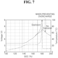
- FIG. 7 is a graph comparing a battery cell in accordance with an exemplary embodiment and a typical battery cell without an overcharge prevention member. At this point, the solid line represents voltages, and the wide width dotted line represents temperatures.
- the cutting part 140 cuts the lead part 130 through a property, in which the temperature is slowly raised and the internal pressure is also increased, and thus, the explosion of the battery cell may be prevented.
- a method for manufacturing a battery cell including an overcharge prevention member such that a cutting part is attached to a cell exterior material, and a lead part of an electrode assembly is positioned on a suitable position of the attached cutting part, prevents explosion due to an internal pressure generated when an overcharge occurs while not affecting charge/discharge.
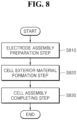
- FIG. 8 is a flow chart of a method for manufacturing a battery cell in accordance with an exemplary embodiment.
- an electrode assembly is prepared through an electrode process firstly (electrode assembly preparation step: S810), and the prepared electrode assembly is accommodated in a cell exterior material provided with a cutting part (cell exterior material formation step: S820).
- the process of the method for manufacturing a battery cell is an assembly process among manufacturing processes, and a process for manufacturing a general battery cell is roughly divided into three processes such as electrode, assembly, and formation processes.
- materials are mixed with an appropriate ratio for manufacturing a positive electrode and a negative electrode; the positive electrode is coated with aluminum and the negative electrode is coated with a copper foil; the resultant is pressed in a constant thickness through a roll press to be flat; and then a slitting process is performed to cut the resultant so as to be matched with the electrode size.
- the assembly process is a process in which a winding step of roundly winding the positive electrode, a separator, and a negative electrode in this order and a stacking step of repeatedly stacking the positive electrode, the separator, and the negative electrode are performed and packaged with a aluminum film wrapping material, and then an electrolyte is added and the resultant is sealed to be a vacuum state, the assembly process being a process of the manufacturing method performed in the present invention.
- the battery cell is activated while repeating charge/discharge of the assembled battery cell, a degassing step of discharging the gas generated in the battery cell is performed during the activation, and then a final battery cell is completed.
- the electrode assembly preparation step (S810) is a step of preparing the electrode assembly through the electrode process, and the electrode assembly is prepared through the method described about the electrode process.
- the cell exterior material formation step (S820) is a step of accommodating the electrode assembly prepared in the electrode assembly preparation step into a cell exterior material provided with the cutting part, and will be described in more detail with reference to FIG. 9 .
- FIG. 9 is a flow chart of a cell exterior material formation step in a method for manufacturing a battery cell in accordance with an exemplary embodiment.
- a first cutter part, a second cutter part, and a third cutter part are attached to the cell exterior material (cutting part attachment step: S821), and the positions of the first cutter part, the second cutter part, and the third cutter part which have been attached are adjusted (position adjustment step: S822).
- the lead part connected to the electrode assembly is positioned in an accommodating space generated by adjusting the positions of the first cutter part, the second cutter part, and the third cutter part (lead part positioning step: S823).
- the cutting part attachment step (S821) is a step of attaching the first cutter part, the second cutter part, and the third cutter part to the cell exterior material, and is subjected to a premise that the cell exterior material, in which an attachment part for attaching the cutting part has been already formed, is prepared.
- the first cutter part is attached to an upper exterior material of the cell exterior material in the direction of the electrode assembly, and then the second cutter part is attached to a lower exterior material of the cell exterior material in the direction opposite to the electrode assembly of the first cutter part.
- the third cutter part is attached to the upper exterior material of the cell exterior material in the direction opposite to the electrode assembly of the second cutter part.
- the position adjustment step (S822) is a step of adjusting the first cutter part, the second cutter part, and the third cutter part which are attached to the cell exterior material, and since each cutter part is attached to only one side of the cell exterior material, the position of each cutter part may be formed at an incorrect position.
- the lead part positioning step (S823) is a step for positioning the lead part connected to the electrode assembly in the accommodating space generated by adjusting the positions of the first cutter part, the second cutter part, and the third cutter part, and is subjected to a premise that a step of jointing the lead part to the electrode assembly has already been performed prior to this step.
- the cell assembly completing step (S830) is a step for injecting an electrolyte into the cell exterior material formed in the cell exterior material formation step and sealing the cell exterior material, and in this step, the electrolyte may be injected after the thermal fusion of the cell exterior material except for a portion thereof, or the entire surface of the cell exterior material is thermally fused, a portion of injection ports is then formed, the electrolyte is injected thereinto, and then the cell exterior material may be fused again.
- a step is performed, in which the battery cell is activated while the battery cell assembled in the above steps is repeatedly charged/discharged, and the gas generated in the battery cell during the activation is discharged, and in this step, a space between the lead part and the cutting part may be ensured by a predetermined range or more so that the cutting part is not operated in this step.
Landscapes
- Chemical & Material Sciences (AREA)
- Chemical Kinetics & Catalysis (AREA)
- Electrochemistry (AREA)
- General Chemical & Material Sciences (AREA)
- Inorganic Chemistry (AREA)
- Connection Of Batteries Or Terminals (AREA)
- Gas Exhaust Devices For Batteries (AREA)
- Sealing Battery Cases Or Jackets (AREA)
- Secondary Cells (AREA)
Claims (5)
- Batteriezelle (100), umfassend:eine Elektrodenbaugruppe (110);ein äußeres Zellmaterial (120), das konfiguriert ist, um die Elektrodenbaugruppe (110) aufzunehmen, und das ein oberes äußeres Material und ein unteres äußeres Material umfasst;ein Bleiteil (130), das sich zwischen dem oberen äußeren Material und dem unteren äußeren Material aus der Elektrodenbaugruppe (110) erstreckt und aus dem äußeren Zellmaterial (120) herausgeführt wird; undgekennzeichnet durch ein schneidendes Teil (140), das an oberen und unteren Enden des Bleiteils (130) positioniert ist und konfiguriert ist, um das Bleiteil (130) zu schneiden und zu trennen, wenn eine Überladung erfolgt,wobei das schneidende Teil (140) umfasst:ein erstes Schneidteil (141), das in der Richtung zur Elektrodenbaugruppe (110) positioniert ist, und einen Rahmen umfasst, der an dem oberen äußeren Material befestigt ist, und eine erste schneidende Klinge aufnimmt;ein zweites Schneidteil (142), das auf der Seite des ersten Schneidteils (141) in der entgegengesetzten Richtung zur Elektrodenbaugruppe (110) positioniert ist, und einen Rahmen umfasst, der an dem unteren äußeren Material befestigt ist, und eine zweite schneidenden Klinge aufnimmt; undein drittes Schneidteil (143), das auf der Seite des zweiten Schneidteils (142) in der entgegengesetzten Richtung zur Elektrodenbaugruppe (110) positioniert ist, und einen Rahmen umfasst, der an dem oberen äußeren Material befestigt ist, und eine dritte schneidende Klinge aufnimmt,wobei, wenn eine Überladung erfolgt, sich die Batteriezelle (100) ausdehnt und ein Abstand zwischen dem oberen äußeren Material und dem unteren äußeren Material zunimmt, und das Bleiteil (130) dadurch abgeschnitten wird,wobei die erste schneidende Klinge des ersten Schneidteils (141) und die dritte schneidende Klinge des dritten Schneidteils (143) jeweils an unteren Endabschnitten der Rahmen des ersten Schneidteils (141) und des dritten Schneidteils (143) vorgesehen sind, und in einem unteren Abschnitt des Bleiteils (130) positioniert sind, wenn das Schneidteil (140) konfiguriert ist, undwobei die zweite schneidende Klinge des zweiten Schneidteils (142) an einem oberen Endabschnitt des zweiten Schneidteils (142) gebildet ist, und in einem oberen Abschnitt des Bleiteils (130) positioniert ist, wenn das Schneidteil (140) konfiguriert ist.
- Batteriezelle nach Anspruch 1, wobei die schneidenden Klingen des ersten Schneidteils (141), des zweiten Schneidteils (142), und des dritten Schneidteils (143) jeweils in von einer Seite zur anderen Seite schräg geneigten Formen vorgesehen sind.
- Batteriezelle nach Anspruch 2, wobei, wenn das Bleiteil (130) angeordnet ist, Abschnitte, in denen die erste, zweite und dritte Klinge zusammentreffen, einen vorbestimmten Aufnahmeraum bilden.
- Verfahren zur Herstellung einer Batteriezelle (100) nach Anspruch 1, wobei das Verfahren umfasst:einen Elektrodenbaugruppen-Vorbereitungsprozess (S810), bei dem die Elektrodenbaugruppe (110) durch einen Elektrodenprozess vorbereitet wird;einen Bildungsprozess eines äußeren Zellmaterials (S820), bei dem die Elektrodenbaugruppe (110), die in dem Elektrodenbaugruppen-Vorbereitungsprozess vorbereitet wird, in einem äußeren Zellmaterial (120) aufgenommen wird, welches das schneidende Teil (140) aufweist; undeinen Elektrodenbaugruppen-Fertigstellungsprozess (S830), bei dem ein Elektrolyt in das äußere Zellmaterial (120), das bei dem Bildungsprozess eines äußeren Zellmaterials gebildet wird, injiziert wird, und das äußere Zellmaterial (120) versiegelt wird.
- Verfahren nach Anspruch 4, wobei der Bildungsprozess eines äußeren Zellmaterials (S820) umfasst:einen Befestigungsprozess eines schneidenden Teils (S821), bei dem das erste Schneidteil, das zweite Schneidteil, und das dritte Schneidteil an dem äußeren Zellmaterial (120) befestigt werden;einen Positionsanpassungsprozess (S822), bei dem Positionen des ersten Schneidteils, des zweiten Schneidteils und des dritten Schneidteils, die in dem Befestigungsprozess eines schneidenden Teils befestigt werden, angepasst werden; undeinen Bleiteil-Positionierungsprozess (S823), bei dem das Bleiteil (130), das mit der Elektrodenbaugruppe (110) verbunden ist, in einem Aufnahmeraum positioniert wird, der durch Anpassen von Positionen in dem Positionsanpassungsprozess erzeugt wird.
Applications Claiming Priority (2)
| Application Number | Priority Date | Filing Date | Title |
|---|---|---|---|
| KR1020170082668A KR102236056B1 (ko) | 2017-06-29 | 2017-06-29 | 과충전 방지부재를 가지는 배터리 셀 |
| PCT/KR2018/000529 WO2019004545A1 (ko) | 2017-06-29 | 2018-01-11 | 과충전 방지부재를 가지는 배터리 셀 |
Publications (3)
| Publication Number | Publication Date |
|---|---|
| EP3522262A1 EP3522262A1 (de) | 2019-08-07 |
| EP3522262A4 EP3522262A4 (de) | 2019-11-13 |
| EP3522262B1 true EP3522262B1 (de) | 2023-04-12 |
Family
ID=64742315
Family Applications (1)
| Application Number | Title | Priority Date | Filing Date |
|---|---|---|---|
| EP18824555.9A Active EP3522262B1 (de) | 2017-06-29 | 2018-01-11 | Batteriezelle mit überladeschutzelement |
Country Status (5)
| Country | Link |
|---|---|
| US (1) | US11258146B2 (de) |
| EP (1) | EP3522262B1 (de) |
| KR (1) | KR102236056B1 (de) |
| CN (1) | CN110476274B (de) |
| WO (1) | WO2019004545A1 (de) |
Families Citing this family (2)
| Publication number | Priority date | Publication date | Assignee | Title |
|---|---|---|---|---|
| KR102655101B1 (ko) * | 2018-11-23 | 2024-04-08 | 주식회사 엘지에너지솔루션 | 배터리 셀의 전극리드 절단장치 |
| EP4539209A3 (de) | 2021-09-27 | 2025-07-30 | QuantumScape Battery, Inc. | Elektrochemischer stapel und verfahren zu seiner montage |
Family Cites Families (19)
| Publication number | Priority date | Publication date | Assignee | Title |
|---|---|---|---|---|
| US5352547A (en) * | 1992-08-27 | 1994-10-04 | Hitachi Maxell, Ltd. | Organic electrolytic solution and organic electrolytic solution cell |
| JP4132588B2 (ja) | 2000-06-16 | 2008-08-13 | Tdk株式会社 | 電気化学デバイス |
| JP4154888B2 (ja) | 2001-12-03 | 2008-09-24 | 日産自動車株式会社 | 電池モジュール及び電池モジュールを備えた車両 |
| JP2007520180A (ja) | 2003-10-14 | 2007-07-19 | ブラック アンド デッカー インク | 電池パックの障害状態からの保護を提供するべく適合された二次電池、電動工具、充電器、及び電池パック用の保護方法、保護回路、及び保護装置 |
| KR100553215B1 (ko) | 2003-12-26 | 2006-02-22 | 주식회사 엘지화학 | 안전성을 향상시키는 내부 지지대를 구비한 리튬이차전지 |
| CN102044655B (zh) * | 2009-10-19 | 2012-11-21 | 有量科技股份有限公司 | 电池过充自动断电装置及具有过充自动断电装置的电池 |
| JP5404527B2 (ja) * | 2010-05-24 | 2014-02-05 | Fdk株式会社 | 防爆機能付き蓄電モジュール |
| KR101294168B1 (ko) | 2011-09-26 | 2013-08-08 | 기아자동차주식회사 | 배터리의 과충전 방지장치 |
| KR101623110B1 (ko) * | 2012-10-18 | 2016-05-20 | 주식회사 엘지화학 | 전극 리드 및 이를 포함하는 이차 전지 |
| KR101500229B1 (ko) | 2013-12-18 | 2015-03-06 | 현대자동차주식회사 | 차량 배터리 과충전 방지장치 |
| KR101500222B1 (ko) * | 2013-12-18 | 2015-03-06 | 현대자동차주식회사 | 배터리 과충전 방지 장치 |
| KR102177506B1 (ko) * | 2014-07-30 | 2020-11-11 | 삼성에스디아이 주식회사 | 이차 전지 및 그 제조 방법 |
| KR101704129B1 (ko) | 2014-11-20 | 2017-02-07 | 현대자동차주식회사 | 스웰링 cid |
| KR102384912B1 (ko) | 2015-06-12 | 2022-04-11 | 에스케이온 주식회사 | 이차전지 및 이를 포함하는 배터리 모듈 |
| KR102324360B1 (ko) * | 2015-08-17 | 2021-11-09 | 에스케이이노베이션 주식회사 | 이차전지 및 이를 포함하는 이차전지 모듈 |
| KR102056363B1 (ko) | 2015-08-17 | 2019-12-16 | 주식회사 엘지화학 | 전지 셀 |
| KR102053987B1 (ko) | 2015-08-27 | 2019-12-09 | 주식회사 엘지화학 | 전지 셀 |
| US10109842B2 (en) * | 2015-10-16 | 2018-10-23 | Hyundai Motor Company | Battery cell |
| KR101766047B1 (ko) * | 2015-10-22 | 2017-08-07 | 현대자동차주식회사 | 배터리 셀 |
-
2017
- 2017-06-29 KR KR1020170082668A patent/KR102236056B1/ko active Active
-
2018
- 2018-01-11 CN CN201880020256.5A patent/CN110476274B/zh active Active
- 2018-01-11 WO PCT/KR2018/000529 patent/WO2019004545A1/ko not_active Ceased
- 2018-01-11 US US16/627,022 patent/US11258146B2/en active Active
- 2018-01-11 EP EP18824555.9A patent/EP3522262B1/de active Active
Also Published As
| Publication number | Publication date |
|---|---|
| KR20190002156A (ko) | 2019-01-08 |
| US11258146B2 (en) | 2022-02-22 |
| EP3522262A4 (de) | 2019-11-13 |
| EP3522262A1 (de) | 2019-08-07 |
| KR102236056B1 (ko) | 2021-04-05 |
| CN110476274B (zh) | 2022-05-17 |
| CN110476274A (zh) | 2019-11-19 |
| US20200119329A1 (en) | 2020-04-16 |
| WO2019004545A1 (ko) | 2019-01-03 |
Similar Documents
| Publication | Publication Date | Title |
|---|---|---|
| KR101521158B1 (ko) | 리튬-이온 전지에 대한 cid 보유 장치 | |
| EP2822062B1 (de) | Sekundärbatterie mit integrierter anodenleitung und kathodenleitung sowie herstellungsverfahren dafür | |
| US8486546B2 (en) | Cap assembly and secondary battery using the same with notched vent member | |
| US10141553B2 (en) | Secondary battery and battery module having the same | |
| US8802281B2 (en) | Secondary battery with movement prevention tape | |
| EP2156488B1 (de) | Batteriezelle mit verbesserter sicherheit | |
| EP1519428B1 (de) | Hochsicherheits Lithium-Sekundärbatterie und Verfahren zu deren Herstellung | |
| US11289782B2 (en) | Secondary battery | |
| KR100864694B1 (ko) | 파우치 전지용 형상기억 튜브로 구성된 고온 안전변 | |
| US20040126650A1 (en) | Electrode assembly for lithium ion cell and lithium cell using the same | |
| CN102195075A (zh) | 圆筒形非水电解质电池 | |
| US10862097B2 (en) | Secondary battery | |
| CN102017231A (zh) | 具有增进安全性的电池组 | |
| KR100610261B1 (ko) | 안전성을 향상시킨 이종 분리막 구조의 리튬이차전지 | |
| US20180219208A1 (en) | Lithium storage battery with integrated circuit-breaker for improved operating safety | |
| KR102561111B1 (ko) | 이차전지 | |
| US11355825B2 (en) | Battery pack and manufacturing method therefor | |
| US20180219209A1 (en) | Lithium storage battery with integrated circuit-breaker for improved operating safety | |
| KR20110018415A (ko) | 조립 밀봉체 및 그것을 이용한 전지 | |
| JP5099880B2 (ja) | リチウムイオン二次電池およびリチウムイオン二次電池の組電池 | |
| EP3522262B1 (de) | Batteriezelle mit überladeschutzelement | |
| JP2003208885A (ja) | シート状電池 | |
| KR20200099392A (ko) | 이차 전지 및 전지 모듈 | |
| JP2005251548A (ja) | 角形二次電池 | |
| KR20220033944A (ko) | 전극 조립체 및 이차 전지 |
Legal Events
| Date | Code | Title | Description |
|---|---|---|---|
| STAA | Information on the status of an ep patent application or granted ep patent |
Free format text: STATUS: THE INTERNATIONAL PUBLICATION HAS BEEN MADE |
|
| PUAI | Public reference made under article 153(3) epc to a published international application that has entered the european phase |
Free format text: ORIGINAL CODE: 0009012 |
|
| STAA | Information on the status of an ep patent application or granted ep patent |
Free format text: STATUS: REQUEST FOR EXAMINATION WAS MADE |
|
| 17P | Request for examination filed |
Effective date: 20190503 |
|
| AK | Designated contracting states |
Kind code of ref document: A1 Designated state(s): AL AT BE BG CH CY CZ DE DK EE ES FI FR GB GR HR HU IE IS IT LI LT LU LV MC MK MT NL NO PL PT RO RS SE SI SK SM TR |
|
| AX | Request for extension of the european patent |
Extension state: BA ME |
|
| A4 | Supplementary search report drawn up and despatched |
Effective date: 20191016 |
|
| RIC1 | Information provided on ipc code assigned before grant |
Ipc: H01M 2/02 20060101ALI20191010BHEP Ipc: H01M 2/12 20060101ALI20191010BHEP Ipc: H01M 2/34 20060101AFI20191010BHEP |
|
| DAV | Request for validation of the european patent (deleted) | ||
| DAX | Request for extension of the european patent (deleted) | ||
| RAP1 | Party data changed (applicant data changed or rights of an application transferred) |
Owner name: LG ENERGY SOLUTION LTD. |
|
| RAP3 | Party data changed (applicant data changed or rights of an application transferred) |
Owner name: LG ENERGY SOLUTION, LTD. |
|
| REG | Reference to a national code |
Ref country code: DE Ref legal event code: R079 Ref document number: 602018048388 Country of ref document: DE Free format text: PREVIOUS MAIN CLASS: H01M0002340000 Ipc: H01M0050105000 |
|
| RIC1 | Information provided on ipc code assigned before grant |
Ipc: H01M 50/583 20210101ALI20221005BHEP Ipc: H01M 50/553 20210101ALI20221005BHEP Ipc: H01M 50/548 20210101ALI20221005BHEP Ipc: H01M 50/178 20210101ALI20221005BHEP Ipc: H01M 50/105 20210101AFI20221005BHEP |
|
| GRAP | Despatch of communication of intention to grant a patent |
Free format text: ORIGINAL CODE: EPIDOSNIGR1 |
|
| STAA | Information on the status of an ep patent application or granted ep patent |
Free format text: STATUS: GRANT OF PATENT IS INTENDED |
|
| INTG | Intention to grant announced |
Effective date: 20221124 |
|
| GRAS | Grant fee paid |
Free format text: ORIGINAL CODE: EPIDOSNIGR3 |
|
| GRAA | (expected) grant |
Free format text: ORIGINAL CODE: 0009210 |
|
| STAA | Information on the status of an ep patent application or granted ep patent |
Free format text: STATUS: THE PATENT HAS BEEN GRANTED |
|
| AK | Designated contracting states |
Kind code of ref document: B1 Designated state(s): AL AT BE BG CH CY CZ DE DK EE ES FI FR GB GR HR HU IE IS IT LI LT LU LV MC MK MT NL NO PL PT RO RS SE SI SK SM TR |
|
| REG | Reference to a national code |
Ref country code: GB Ref legal event code: FG4D |
|
| REG | Reference to a national code |
Ref country code: CH Ref legal event code: EP |
|
| REG | Reference to a national code |
Ref country code: DE Ref legal event code: R096 Ref document number: 602018048388 Country of ref document: DE |
|
| REG | Reference to a national code |
Ref country code: IE Ref legal event code: FG4D |
|
| REG | Reference to a national code |
Ref country code: AT Ref legal event code: REF Ref document number: 1560298 Country of ref document: AT Kind code of ref document: T Effective date: 20230515 |
|
| P01 | Opt-out of the competence of the unified patent court (upc) registered |
Effective date: 20230408 |
|
| REG | Reference to a national code |
Ref country code: LT Ref legal event code: MG9D |
|
| REG | Reference to a national code |
Ref country code: NL Ref legal event code: MP Effective date: 20230412 |
|
| REG | Reference to a national code |
Ref country code: AT Ref legal event code: MK05 Ref document number: 1560298 Country of ref document: AT Kind code of ref document: T Effective date: 20230412 |
|
| PG25 | Lapsed in a contracting state [announced via postgrant information from national office to epo] |
Ref country code: NL Free format text: LAPSE BECAUSE OF FAILURE TO SUBMIT A TRANSLATION OF THE DESCRIPTION OR TO PAY THE FEE WITHIN THE PRESCRIBED TIME-LIMIT Effective date: 20230412 |
|
| PG25 | Lapsed in a contracting state [announced via postgrant information from national office to epo] |
Ref country code: SE Free format text: LAPSE BECAUSE OF FAILURE TO SUBMIT A TRANSLATION OF THE DESCRIPTION OR TO PAY THE FEE WITHIN THE PRESCRIBED TIME-LIMIT Effective date: 20230412 Ref country code: PT Free format text: LAPSE BECAUSE OF FAILURE TO SUBMIT A TRANSLATION OF THE DESCRIPTION OR TO PAY THE FEE WITHIN THE PRESCRIBED TIME-LIMIT Effective date: 20230814 Ref country code: NO Free format text: LAPSE BECAUSE OF FAILURE TO SUBMIT A TRANSLATION OF THE DESCRIPTION OR TO PAY THE FEE WITHIN THE PRESCRIBED TIME-LIMIT Effective date: 20230712 Ref country code: ES Free format text: LAPSE BECAUSE OF FAILURE TO SUBMIT A TRANSLATION OF THE DESCRIPTION OR TO PAY THE FEE WITHIN THE PRESCRIBED TIME-LIMIT Effective date: 20230412 Ref country code: AT Free format text: LAPSE BECAUSE OF FAILURE TO SUBMIT A TRANSLATION OF THE DESCRIPTION OR TO PAY THE FEE WITHIN THE PRESCRIBED TIME-LIMIT Effective date: 20230412 |
|
| PG25 | Lapsed in a contracting state [announced via postgrant information from national office to epo] |
Ref country code: RS Free format text: LAPSE BECAUSE OF FAILURE TO SUBMIT A TRANSLATION OF THE DESCRIPTION OR TO PAY THE FEE WITHIN THE PRESCRIBED TIME-LIMIT Effective date: 20230412 Ref country code: PL Free format text: LAPSE BECAUSE OF FAILURE TO SUBMIT A TRANSLATION OF THE DESCRIPTION OR TO PAY THE FEE WITHIN THE PRESCRIBED TIME-LIMIT Effective date: 20230412 Ref country code: LV Free format text: LAPSE BECAUSE OF FAILURE TO SUBMIT A TRANSLATION OF THE DESCRIPTION OR TO PAY THE FEE WITHIN THE PRESCRIBED TIME-LIMIT Effective date: 20230412 Ref country code: LT Free format text: LAPSE BECAUSE OF FAILURE TO SUBMIT A TRANSLATION OF THE DESCRIPTION OR TO PAY THE FEE WITHIN THE PRESCRIBED TIME-LIMIT Effective date: 20230412 Ref country code: IS Free format text: LAPSE BECAUSE OF FAILURE TO SUBMIT A TRANSLATION OF THE DESCRIPTION OR TO PAY THE FEE WITHIN THE PRESCRIBED TIME-LIMIT Effective date: 20230812 Ref country code: HR Free format text: LAPSE BECAUSE OF FAILURE TO SUBMIT A TRANSLATION OF THE DESCRIPTION OR TO PAY THE FEE WITHIN THE PRESCRIBED TIME-LIMIT Effective date: 20230412 Ref country code: GR Free format text: LAPSE BECAUSE OF FAILURE TO SUBMIT A TRANSLATION OF THE DESCRIPTION OR TO PAY THE FEE WITHIN THE PRESCRIBED TIME-LIMIT Effective date: 20230713 Ref country code: AL Free format text: LAPSE BECAUSE OF FAILURE TO SUBMIT A TRANSLATION OF THE DESCRIPTION OR TO PAY THE FEE WITHIN THE PRESCRIBED TIME-LIMIT Effective date: 20230412 |
|
| PG25 | Lapsed in a contracting state [announced via postgrant information from national office to epo] |
Ref country code: FI Free format text: LAPSE BECAUSE OF FAILURE TO SUBMIT A TRANSLATION OF THE DESCRIPTION OR TO PAY THE FEE WITHIN THE PRESCRIBED TIME-LIMIT Effective date: 20230412 |
|
| REG | Reference to a national code |
Ref country code: DE Ref legal event code: R097 Ref document number: 602018048388 Country of ref document: DE |
|
| PG25 | Lapsed in a contracting state [announced via postgrant information from national office to epo] |
Ref country code: SK Free format text: LAPSE BECAUSE OF FAILURE TO SUBMIT A TRANSLATION OF THE DESCRIPTION OR TO PAY THE FEE WITHIN THE PRESCRIBED TIME-LIMIT Effective date: 20230412 |
|
| PG25 | Lapsed in a contracting state [announced via postgrant information from national office to epo] |
Ref country code: SM Free format text: LAPSE BECAUSE OF FAILURE TO SUBMIT A TRANSLATION OF THE DESCRIPTION OR TO PAY THE FEE WITHIN THE PRESCRIBED TIME-LIMIT Effective date: 20230412 Ref country code: SK Free format text: LAPSE BECAUSE OF FAILURE TO SUBMIT A TRANSLATION OF THE DESCRIPTION OR TO PAY THE FEE WITHIN THE PRESCRIBED TIME-LIMIT Effective date: 20230412 Ref country code: RO Free format text: LAPSE BECAUSE OF FAILURE TO SUBMIT A TRANSLATION OF THE DESCRIPTION OR TO PAY THE FEE WITHIN THE PRESCRIBED TIME-LIMIT Effective date: 20230412 Ref country code: EE Free format text: LAPSE BECAUSE OF FAILURE TO SUBMIT A TRANSLATION OF THE DESCRIPTION OR TO PAY THE FEE WITHIN THE PRESCRIBED TIME-LIMIT Effective date: 20230412 Ref country code: DK Free format text: LAPSE BECAUSE OF FAILURE TO SUBMIT A TRANSLATION OF THE DESCRIPTION OR TO PAY THE FEE WITHIN THE PRESCRIBED TIME-LIMIT Effective date: 20230412 Ref country code: CZ Free format text: LAPSE BECAUSE OF FAILURE TO SUBMIT A TRANSLATION OF THE DESCRIPTION OR TO PAY THE FEE WITHIN THE PRESCRIBED TIME-LIMIT Effective date: 20230412 |
|
| PLBE | No opposition filed within time limit |
Free format text: ORIGINAL CODE: 0009261 |
|
| STAA | Information on the status of an ep patent application or granted ep patent |
Free format text: STATUS: NO OPPOSITION FILED WITHIN TIME LIMIT |
|
| 26N | No opposition filed |
Effective date: 20240115 |
|
| PG25 | Lapsed in a contracting state [announced via postgrant information from national office to epo] |
Ref country code: SI Free format text: LAPSE BECAUSE OF FAILURE TO SUBMIT A TRANSLATION OF THE DESCRIPTION OR TO PAY THE FEE WITHIN THE PRESCRIBED TIME-LIMIT Effective date: 20230412 |
|
| PG25 | Lapsed in a contracting state [announced via postgrant information from national office to epo] |
Ref country code: SI Free format text: LAPSE BECAUSE OF FAILURE TO SUBMIT A TRANSLATION OF THE DESCRIPTION OR TO PAY THE FEE WITHIN THE PRESCRIBED TIME-LIMIT Effective date: 20230412 Ref country code: IT Free format text: LAPSE BECAUSE OF FAILURE TO SUBMIT A TRANSLATION OF THE DESCRIPTION OR TO PAY THE FEE WITHIN THE PRESCRIBED TIME-LIMIT Effective date: 20230412 |
|
| PG25 | Lapsed in a contracting state [announced via postgrant information from national office to epo] |
Ref country code: MC Free format text: LAPSE BECAUSE OF FAILURE TO SUBMIT A TRANSLATION OF THE DESCRIPTION OR TO PAY THE FEE WITHIN THE PRESCRIBED TIME-LIMIT Effective date: 20230412 |
|
| PG25 | Lapsed in a contracting state [announced via postgrant information from national office to epo] |
Ref country code: MC Free format text: LAPSE BECAUSE OF FAILURE TO SUBMIT A TRANSLATION OF THE DESCRIPTION OR TO PAY THE FEE WITHIN THE PRESCRIBED TIME-LIMIT Effective date: 20230412 |
|
| REG | Reference to a national code |
Ref country code: CH Ref legal event code: PL |
|
| PG25 | Lapsed in a contracting state [announced via postgrant information from national office to epo] |
Ref country code: LU Free format text: LAPSE BECAUSE OF NON-PAYMENT OF DUE FEES Effective date: 20240111 |
|
| PG25 | Lapsed in a contracting state [announced via postgrant information from national office to epo] |
Ref country code: LU Free format text: LAPSE BECAUSE OF NON-PAYMENT OF DUE FEES Effective date: 20240111 |
|
| PG25 | Lapsed in a contracting state [announced via postgrant information from national office to epo] |
Ref country code: BE Free format text: LAPSE BECAUSE OF NON-PAYMENT OF DUE FEES Effective date: 20240131 |
|
| PG25 | Lapsed in a contracting state [announced via postgrant information from national office to epo] |
Ref country code: CH Free format text: LAPSE BECAUSE OF NON-PAYMENT OF DUE FEES Effective date: 20240131 |
|
| PG25 | Lapsed in a contracting state [announced via postgrant information from national office to epo] |
Ref country code: CH Free format text: LAPSE BECAUSE OF NON-PAYMENT OF DUE FEES Effective date: 20240131 Ref country code: BE Free format text: LAPSE BECAUSE OF NON-PAYMENT OF DUE FEES Effective date: 20240131 |
|
| REG | Reference to a national code |
Ref country code: BE Ref legal event code: MM Effective date: 20240131 |
|
| PG25 | Lapsed in a contracting state [announced via postgrant information from national office to epo] |
Ref country code: BG Free format text: LAPSE BECAUSE OF FAILURE TO SUBMIT A TRANSLATION OF THE DESCRIPTION OR TO PAY THE FEE WITHIN THE PRESCRIBED TIME-LIMIT Effective date: 20230412 |
|
| PG25 | Lapsed in a contracting state [announced via postgrant information from national office to epo] |
Ref country code: BG Free format text: LAPSE BECAUSE OF FAILURE TO SUBMIT A TRANSLATION OF THE DESCRIPTION OR TO PAY THE FEE WITHIN THE PRESCRIBED TIME-LIMIT Effective date: 20230412 |
|
| PG25 | Lapsed in a contracting state [announced via postgrant information from national office to epo] |
Ref country code: IE Free format text: LAPSE BECAUSE OF NON-PAYMENT OF DUE FEES Effective date: 20240111 |
|
| PG25 | Lapsed in a contracting state [announced via postgrant information from national office to epo] |
Ref country code: IE Free format text: LAPSE BECAUSE OF NON-PAYMENT OF DUE FEES Effective date: 20240111 |
|
| PG25 | Lapsed in a contracting state [announced via postgrant information from national office to epo] |
Ref country code: CY Free format text: LAPSE BECAUSE OF FAILURE TO SUBMIT A TRANSLATION OF THE DESCRIPTION OR TO PAY THE FEE WITHIN THE PRESCRIBED TIME-LIMIT; INVALID AB INITIO Effective date: 20180111 |
|
| PG25 | Lapsed in a contracting state [announced via postgrant information from national office to epo] |
Ref country code: HU Free format text: LAPSE BECAUSE OF FAILURE TO SUBMIT A TRANSLATION OF THE DESCRIPTION OR TO PAY THE FEE WITHIN THE PRESCRIBED TIME-LIMIT; INVALID AB INITIO Effective date: 20180111 |
|
| PG25 | Lapsed in a contracting state [announced via postgrant information from national office to epo] |
Ref country code: TR Free format text: LAPSE BECAUSE OF FAILURE TO SUBMIT A TRANSLATION OF THE DESCRIPTION OR TO PAY THE FEE WITHIN THE PRESCRIBED TIME-LIMIT Effective date: 20230412 |
|
| PGFP | Annual fee paid to national office [announced via postgrant information from national office to epo] |
Ref country code: GB Payment date: 20251222 Year of fee payment: 9 |
|
| PGFP | Annual fee paid to national office [announced via postgrant information from national office to epo] |
Ref country code: FR Payment date: 20251223 Year of fee payment: 9 |
|
| PGFP | Annual fee paid to national office [announced via postgrant information from national office to epo] |
Ref country code: DE Payment date: 20251222 Year of fee payment: 9 |