EP3522126A1 - Dispositif vestimentaire et son système de surveillance - Google Patents
Dispositif vestimentaire et son système de surveillance Download PDFInfo
- Publication number
- EP3522126A1 EP3522126A1 EP16918126.0A EP16918126A EP3522126A1 EP 3522126 A1 EP3522126 A1 EP 3522126A1 EP 16918126 A EP16918126 A EP 16918126A EP 3522126 A1 EP3522126 A1 EP 3522126A1
- Authority
- EP
- European Patent Office
- Prior art keywords
- wearable device
- signal
- power source
- region
- signal transceiver
- Prior art date
- Legal status (The legal status is an assumption and is not a legal conclusion. Google has not performed a legal analysis and makes no representation as to the accuracy of the status listed.)
- Pending
Links
Images

Classifications
-
- F—MECHANICAL ENGINEERING; LIGHTING; HEATING; WEAPONS; BLASTING
- F16—ENGINEERING ELEMENTS AND UNITS; GENERAL MEASURES FOR PRODUCING AND MAINTAINING EFFECTIVE FUNCTIONING OF MACHINES OR INSTALLATIONS; THERMAL INSULATION IN GENERAL
- F16P—SAFETY DEVICES IN GENERAL; SAFETY DEVICES FOR PRESSES
- F16P3/00—Safety devices acting in conjunction with the control or operation of a machine; Control arrangements requiring the simultaneous use of two or more parts of the body
- F16P3/12—Safety devices acting in conjunction with the control or operation of a machine; Control arrangements requiring the simultaneous use of two or more parts of the body with means, e.g. feelers, which in case of the presence of a body part of a person in or near the danger zone influence the control or operation of the machine
- F16P3/14—Safety devices acting in conjunction with the control or operation of a machine; Control arrangements requiring the simultaneous use of two or more parts of the body with means, e.g. feelers, which in case of the presence of a body part of a person in or near the danger zone influence the control or operation of the machine the means being photocells or other devices sensitive without mechanical contact
- F16P3/147—Safety devices acting in conjunction with the control or operation of a machine; Control arrangements requiring the simultaneous use of two or more parts of the body with means, e.g. feelers, which in case of the presence of a body part of a person in or near the danger zone influence the control or operation of the machine the means being photocells or other devices sensitive without mechanical contact using electro-magnetic technology, e.g. tags or radar
-
- A—HUMAN NECESSITIES
- A61—MEDICAL OR VETERINARY SCIENCE; HYGIENE
- A61B—DIAGNOSIS; SURGERY; IDENTIFICATION
- A61B5/00—Measuring for diagnostic purposes; Identification of persons
- A61B5/68—Arrangements of detecting, measuring or recording means, e.g. sensors, in relation to patient
- A61B5/6801—Arrangements of detecting, measuring or recording means, e.g. sensors, in relation to patient specially adapted to be attached to or worn on the body surface
- A61B5/6802—Sensor mounted on worn items
- A61B5/6804—Garments; Clothes
-
- G—PHYSICS
- G06—COMPUTING; CALCULATING OR COUNTING
- G06T—IMAGE DATA PROCESSING OR GENERATION, IN GENERAL
- G06T7/00—Image analysis
- G06T7/20—Analysis of motion
-
- G—PHYSICS
- G08—SIGNALLING
- G08B—SIGNALLING OR CALLING SYSTEMS; ORDER TELEGRAPHS; ALARM SYSTEMS
- G08B21/00—Alarms responsive to a single specified undesired or abnormal condition and not otherwise provided for
- G08B21/02—Alarms for ensuring the safety of persons
- G08B21/0202—Child monitoring systems using a transmitter-receiver system carried by the parent and the child
- G08B21/023—Power management, e.g. system sleep and wake up provisions
-
- G—PHYSICS
- G08—SIGNALLING
- G08B—SIGNALLING OR CALLING SYSTEMS; ORDER TELEGRAPHS; ALARM SYSTEMS
- G08B21/00—Alarms responsive to a single specified undesired or abnormal condition and not otherwise provided for
- G08B21/02—Alarms for ensuring the safety of persons
- G08B21/0202—Child monitoring systems using a transmitter-receiver system carried by the parent and the child
- G08B21/028—Communication between parent and child units via remote transmission means, e.g. satellite network
-
- G—PHYSICS
- G08—SIGNALLING
- G08B—SIGNALLING OR CALLING SYSTEMS; ORDER TELEGRAPHS; ALARM SYSTEMS
- G08B21/00—Alarms responsive to a single specified undesired or abnormal condition and not otherwise provided for
- G08B21/02—Alarms for ensuring the safety of persons
- G08B21/04—Alarms for ensuring the safety of persons responsive to non-activity, e.g. of elderly persons
- G08B21/0438—Sensor means for detecting
- G08B21/0446—Sensor means for detecting worn on the body to detect changes of posture, e.g. a fall, inclination, acceleration, gait
-
- G—PHYSICS
- G08—SIGNALLING
- G08B—SIGNALLING OR CALLING SYSTEMS; ORDER TELEGRAPHS; ALARM SYSTEMS
- G08B25/00—Alarm systems in which the location of the alarm condition is signalled to a central station, e.g. fire or police telegraphic systems
- G08B25/01—Alarm systems in which the location of the alarm condition is signalled to a central station, e.g. fire or police telegraphic systems characterised by the transmission medium
- G08B25/016—Personal emergency signalling and security systems
-
- G—PHYSICS
- G08—SIGNALLING
- G08B—SIGNALLING OR CALLING SYSTEMS; ORDER TELEGRAPHS; ALARM SYSTEMS
- G08B25/00—Alarm systems in which the location of the alarm condition is signalled to a central station, e.g. fire or police telegraphic systems
- G08B25/01—Alarm systems in which the location of the alarm condition is signalled to a central station, e.g. fire or police telegraphic systems characterised by the transmission medium
- G08B25/08—Alarm systems in which the location of the alarm condition is signalled to a central station, e.g. fire or police telegraphic systems characterised by the transmission medium using communication transmission lines
Definitions
- the present invention relates to monitoring technology, more specifically to a wearable device which can be used in a monitored site.
- a common approach is to install a warning sign in a region comprising high-speed industrial robots or dangerous equipment.
- a better approach is to install not only a warning sign but also a protective fence, etc.
- special attendants are provided, for the purpose of preventing unauthorized staff from entering or reminding operators to take care, etc.
- the present invention provides a wearable device, to be worn by staff entering a site to be monitored, so as to facilitate monitoring.
- the wearable device comprises: a power source; a position sensor electrically connected to the power source, for sensing a position of a wearer of the wearable device and generating a position signal; a signal transceiver electrically connected to the power source, for receiving the position signal, sending the position signal to a monitoring apparatus, and receiving an indication signal from the monitoring apparatus; and a body of the wearable device comprises a first part and a second part, wherein a relative position of a moveable end of the first part and a moveable end of the second part can switch between a first relative position and a second relative position.
- the switching of the relative position between the first relative position and the second relative position can turn the power source on or off.
- the position sensor comprises a first position sensor and a second position sensor
- the signal transceiver comprises a first signal transceiver and a second signal transceiver, the first position sensor and the first signal transceiver being disposed at the first part, and the second position sensor and the second signal transceiver being disposed at the second part.
- the power source is disposed on a power source carrier, the first part being pivot-connected by means of a non-moveable end thereof to one end of the power source carrier, and the second part being pivot-connected by means of a non-moveable end thereof to another end of the power source carrier.
- the switching of position of the moveable end of the first part between the first relative position and the second relative position can cause the power source to supply power or stop supplying power to the first signal transceiver and the first position sensor
- the switching of position of the moveable end of the second part between the first relative position and the second relative position can cause the power source to supply power or stop supplying power to the second signal transceiver and the second position sensor.
- the wearable device further comprises an indication module, set to make a corresponding indication when the signal transceiver receives an indication signal from the monitoring apparatus. For example, if the indication signal indicates that the wearer is located in a region requiring a warning, then the indication module issues e.g. a yellow light to show a reminder; if the indication signal indicates that the wearer is located in a highly dangerous region, then the indication module issues e.g. a red light to provide a reminder.
- an indication module set to make a corresponding indication when the signal transceiver receives an indication signal from the monitoring apparatus. For example, if the indication signal indicates that the wearer is located in a region requiring a warning, then the indication module issues e.g. a yellow light to show a reminder; if the indication signal indicates that the wearer is located in a highly dangerous region, then the indication module issues e.g. a red light to provide a reminder.
- a wearing region is any one of a neck, a wrist and a head.
- a monitoring system comprising a wearable device and a monitoring apparatus in communicative connection with each other, wherein the wearable device is any one of the wearable devices described above.
- a monitoring method comprising: providing a wearable device to an entering staff member, the wearable device being set to comprise a position sensor and a signal transceiver; the wearable device in an operational state sensing position information of the entering staff member, and transmitting a sensing signal indicating position information to a monitoring apparatus; the monitoring apparatus determining whether a position of the entering staff member is in a safe region, a region requiring a warning or a highly dangerous region on the basis of the sensing signal; the monitoring apparatus performing a corresponding operation on the basis of the determined region.
- Fig. 1 is a structural schematic diagram of a wearable device according to an example of the present invention.
- the wearable device comprises a power source 12, a position sensor 14 and a signal transceiver 16.
- the power source 12, position sensor 14 and signal transceiver 16 are all disposed on a body 10 of the wearable device.
- disposing a component on the body 10 of the wearable device should be understood as meaning that the component is disposed on a surface of the body 10, or the component is disposed in the body 10, or a part of the component is disposed in the body 10 while another part can protrude from the body 10 or be outside the body 10, or the component is connected to the body 10 in a suitable manner.
- Both the position sensor 14 and the signal transceiver 16 are electrically connected to the power source 12, wherein the power source 12, when turned on, supplies power to the position sensor 14 and the signal transceiver 16.
- the position sensor 14 is used to sense a position of a wearer wearing the wearable device, and generates a position signal.
- the position sensor 14 is for example an ultra-wideband module, i.e. a UWB positioning module, and the UWB positioning module may be realized as a UWB positioning chip.
- the signal transceiver 16 and the position sensor 14 are electrically connected to each other. In some examples, they are realized in the same module or integrated together.
- the position signal generated by the position sensor 14 is sent out via the signal transceiver 16.
- the signal transceiver 16 sends the position signal to a monitoring apparatus.
- the signal transceiver 16 also receives an indication signal from the monitoring apparatus.
- the indication signal indicates whether the wearer is in a region requiring a warning, a highly dangerous region or a safe region of a site entered by the wearer.
- the signal transceiver 16 may be realized as an antenna.
- the wearer After putting on the wearable device, the wearer turns on the power source 12, such that the power source supplies power to the position sensor 14 and the signal transceiver 16.
- the position sensor 14 senses a position of the wearer, and transmits to the signal transceiver 16 a position signal generated on the basis of sensing; the signal transceiver 16 then transmits the position signal to the monitoring apparatus.
- the monitoring apparatus accordingly determines the position of the wearer and determines whether the wearer is in a region requiring a warning, a highly dangerous region or a safe region, and sends an indication signal to the wearable apparatus according to a determination result; the signal transceiver 16 receives the indication signal.
- the body 10 of the wearable device comprises a first part and a second part, and a relative position of a moveable end of the first part and a moveable end of the second part can switch between a first relative position and a second relative position.
- the wearable device can be fixed to a wearing region by means of an action between the moveable end of the first part and the moveable end of the second part on the one hand and a wearing region on the other.
- the wearable device is a pair of spectacles
- the pair of spectacles is fixed to a head through an action between an ear and a moveable end of one spectacles arm serving as the first part, and an action between another ear and a moveable end of another spectacles arm serving as the second part.
- the position sensor 14 comprises a first position sensor and a second position sensor
- the signal transceiver 16 comprises a first signal transceiver and a second signal transceiver.
- the first position sensor and the second position sensor back up each other; the first signal transceiver and the second signal transceiver back up each other.
- a first switch and a second switch are provided for the power source 12.
- the first switch When the first switch is turned on, the first position sensor of the position sensor 14 and the first signal transceiver of the signal transceiver 16 operate; when the second switch is turned on, the second position sensor of the position sensor 14 and the second signal transceiver of the signal transceiver 16 operate.
- the second position sensor and the second transceiver serve as backup for the first position sensor and the first signal transceiver respectively, if either one of the first position sensor and the first transceiver develops a fault, the backup second position sensor and second signal transceiver are activated by turning on the second switch.
- a first switch, a second switch and a third switch are provided for the power source 12.
- the first switch When the first switch is turned on, the first position sensor of the position sensor 14 and the first signal transceiver of the signal transceiver 16 operate; when the second switch is turned on, the second position sensor of the position sensor 14 is supplied with power; when the third switch is turned on, the second signal transceiver of the signal transceiver 16 operates.
- the second position sensor in the case of a fault in the first position sensor, the second position sensor is activated by means of the second switch.
- the second signal transceiver In the case of a fault in the first signal transceiver, the second signal transceiver is activated by means of the third switch.
- the second position sensor is electrically connected to the first signal transceiver, and the second signal transceiver is electrically connected to the first position sensor.
- the first position sensor and the second position sensor when the power source 12 is turned on, simultaneously obtain a supply of power; sensed position signals are transmitted via the first signal transceiver and the second signal transceiver respectively, and received by the monitoring apparatus.
- the power source 12 may be turned on and off by a switch.
- the wearable device shown in fig. 1 further comprises an indication module 18.
- the indication module 18 is electrically connected to the signal transceiver 16. When the signal transceiver 16 receives an indication signal from the monitoring apparatus, indication is performed.
- the indication module may for example be an optical indication module (such as an LED lamp flash, etc.), a buzzer module, an audio indication module or any combination of these modules.
- the indication module 18 for example is used for indicating whether a position of the wearer is dangerous, the degree of danger, etc.
- an optical indication module (if included) of the indication module 18 shows a green colour when the wearer is in a safe region, a yellow colour in a region requiring a warning, and a red colour in a highly dangerous region; in a highly dangerous region, an indication may be made jointly by an optical indication module and an audio indication module or buzzer module (if present) at the same time.
- Fig. 2 is a demonstrative structure of a wearable device according to the present invention.
- the wearable device is intended to be worn on a neck 80 of the wearer.
- the wearable device comprises a first part 20 and a second part 22.
- a moveable end of the first part 20 can move between a position 20A and a position 20B; a moveable end of the second part 22 can move between a position 22A and a position 22B.
- the moveable end of the first part 20 is at position 20A and the moveable end of the second part 22 is at position 22A, this constitutes a first relative position of the moveable end of the first part 20 and the moveable end of the second part 22.
- the moveable end of the first part 20 is at position 20B and the moveable end of the second part 22 is at position 22 B, this constitutes a second relative position of the moveable end of the first part 20 and the moveable end of the second part 22.
- the movement of the moveable end of the first part 20 from position 20A to position 20B and the moveable end of the second part 22 from position 22A to position 22B, i.e. the movement of the two moveable ends from the first relative position to the second relative position, causes the wearable device to be worn on the neck 80 of the wearer.
- a signal transceiver is realized as an antenna, and in this example, the antenna and a position sensor are realized in the same module.
- a first position sensor and a first signal transceiver also called a first antenna hereinbelow
- a second position sensor and a second signal transceiver also called a second antenna hereinbelow
- the first module 30 is disposed at the first part 20
- the second module 32 is disposed at the second part 22.
- the first module 30 is fixed to the first part 20 but extends from the first part 20; the second module 32 is fixed to the second part 22 but extends from the second part 22.
- the first module 30 may be disposed in approximately the middle of the first part 20; the second module 32 may be disposed in approximately the middle of the second part 22. It must be explained that the arrangement of the first module 30 and the second module 32 is not limited to that shown in the present invention; they can be arranged in suitable positions of the first part 20 and the second part 22 according to actual needs.
- a power source 12 is disposed on a power source carrier (not marked); a non-moveable end (not marked) of the first part 20 is pivot-connected to the power source carrier, and a non-moveable end (not marked) of the second part 22 is pivot-connected to the power source carrier.
- the power source 12 when the moveable end of the first part 20 and the moveable end of the second part 22 switch from the first relative position (position 20A and position 22A) to the second relative position (position 20B and position 22B), the power source 12 is turned on, and thereby supplies power to the first module 30 and the second module 32.
- the power source 12 is turned off, and stops supplying power to the first module 30 and the second module 32.
- a first switch 202a and a second switch 202b may be provided.
- the turning-on of the first switch 202a is achieved when the first part 20 switches from position 20A to position 20B, and the turning-on of the second switch 202b is achieved when the second part 22 switches from position 22A to position 22B.
- the first switch 202a is turned off when the first part 20 switches from position 20B to position 20A
- the second switch 202b is turned off when the second part 22 switches from position 22B to position 22A.
- the turning-on and turning-off of the power source 12 may be controlled by just one switch; the "off' and "on" actions of the switch are achieved through the switching of the relative position between the first relative position and the second relative position. For example, when the relative position is the first relative position, the switch is in an OFF state, and when the relative position is the second relative position, the switch is in an ON state.
- the wearable device may further comprise an optical warning module, such as an LED lamp, to issue indication signals by displaying different colours; for example, when a red colour is displayed, this indicates a high level of danger, a yellow colour indicates a warning, and a green colour indicates safety.
- the optical warning module may be formed as a lamp flash.
- an optical warning module 181 is disposed on the power source carrier.
- the optical warning module 181 when an indication signal received by the signal transceiver from a monitoring apparatus indicates that the wearer is in a safe region, the optical warning module 181 shows a green colour; when an indication signal received by the signal transceiver from the monitoring apparatus indicates that the wearer is in a region requiring a warning, the optical warning module 181 shows a yellow colour; when an indication signal received by the signal transceiver from the monitoring apparatus indicates that the wearer is in a highly dangerous region, the optical warning module 181 shows a red colour.
- the wearable device further comprises an indication module disposed at the first part 20 and/or the second part 22, the indication module being used for indicating a charge level of the power source 12, and for example being disposed at an end of the first part and/or the second part 22.
- an audio indication module 182 is disposed at the first part 20 and/or the second part 22 of the wearable device, such that a warning signal etc. can be issued in voice form.
- a buzzer module may also be provided.
- indication modules 120 for indicating the charge level of the power source 12 and audio indication modules 182 are disposed at each of the moveable ends of the first part 20 and the second part 22.
- the indication module for indicating the charge level of the power source 12 may be disposed directly in the vicinity of a battery, or in the case where the wearable device comprises a carrier carrying a battery, disposed on the battery carrier, or if possible, disposed directly on a battery casing, etc.
- the audio indication module may also be disposed in another position of the body as required.
- the power source 12 may be disposed on the first part 20 or the second part 22.
- the power source 12 supplies power to the first module 30 when the first switch is turned on; the power source 12 supplies power to the second module 32 when the second switch is turned on.
- the turning-on of the first switch and the second switch may be achieved by a button, operated manually by the wearer.
- the first part 20 and the second part 22 are pivot-connected by means of the non-moveable ends thereof.
- the power source 12 is disposed at a pivot connection position of the first part 20 and the second part 22; specifically, the first switch is disposed in a place close to the first part 20 at the pivot connection position, and the second switch is disposed in a place close to the second part 22 at the pivot connection position.
- the turning-on of the first switch is achieved when the first part 20 switches from position 20A to position 20B
- the turning-on of the second switch is achieved when the second part 22 switches from position 22A to position 22B.
- the first switch is turned off when the first part 20 switches from position 20B to position 20A
- the second switch is turned off when the second part 22 switches from position 22B to position 22A.
- an alarm button may also be disposed on the body of the wearable device; the alarm button is connected to the power source 12 to obtain power.
- the alarm button is electrically connected to the signal transceiver, so that an alarm signal can be transmitted to the monitoring apparatus by the signal transceiver.
- the alarm button is electrically connected to the audio indication module, so that an alarm signal can issue an audio indication via the audio indication module. The alarm button helps the wearer to issue a distress signal in an emergency or a dangerous situation.
- each module and component is supplied with power by the power source 12.
- the first module 30, the audio indication module disposed at the end of the first part 20, and the indication module indicating the charge level of the power source 12, etc. are all supplied with power by the power source 12 via the first switch when turned on;
- the second module 32, the audio indication module disposed at the end of the second part 22, and the indication module indicating the charge level of the power source 12, etc. are all supplied with power by the power source 12 via the second switch when turned on.
- the optical warning module may be set to be supplied with power when the power source 12 is turned on by the first switch or the second switch.
- the power source 12 may comprise a first power source and a second power source.
- the first power source supplies power to the first position sensor and the first signal transceiver; the second power source supplies power to the second position sensor and the second signal transceiver.
- the first power source may supply power to the charge level indication module and audio indication module disposed on the first part, and the second power source may supply power to the charge level indication module and audio indication module disposed on the second part.
- the first power source supplies power to a first position sensor, a first signal transceiver, a first charge level indication module and an audio indication module disposed on the first part
- the first power source may be controlled by means of a first switch provided therefor.
- the first switch may control turning on/off by means of a button, or may control turning on/off by means of a change in position of the moveable end of the first part as referred to above.
- the second power source supplies power to a second position sensor, a second signal transceiver, a second charge level indication module and an audio indication module disposed on the second part.
- the second switch may control turning on/off by means of a button, or may control turning on/off by means of a change in position of the moveable end of the second part as referred to above.
- positions in which the first power source and the second power source are disposed may be as in the examples described above: disposed on a power source carrier, or disposed in suitable positions of the first part and the second part respectively, or disposed at a pivot connection position of the first part and the second part, etc.
- the other power source can still supply power to the position sensor and the signal transceiver which are electrically connected thereto, so that they can still be in an operational state.
- the staff member may be asked to wear a wearable device according to an example of the present invention, e.g. the wearable device shown in fig. 2 .
- the entering staff member wearing the wearable device operates the first part 20 and the second part 22 to change the positions of the moveable ends thereof, then turns on the power source at the same time as fixing the device to the wearer's neck; the first module, second module and other modules of the wearable device are supplied with power by the power source 12 which has been turned on, thereby entering an operational state.
- the first module 30 and the second module 32 sense a movement position of the wearer in the site, and send sensing signals to a monitoring apparatus by wireless transmission; the monitoring apparatus is for example disposed in a monitoring room.
- Parameters associated with a dangerous region have already been preset for the site in the monitoring apparatus, e.g. a setting has already been performed regarding which region is a safe region, which region is a region requiring a warning, and which region is a highly dangerous region, etc., wherein regions can be set by means of transverse and longitudinal position parameters.
- the monitoring apparatus sends a safe signal to the wearable device; at this time, the optical indication module of the wearable device shows a green colour.
- the monitoring apparatus may also be set to not send a signal when the wearer is in a safe region, and the optical indication module is set to show a green colour in this case.
- the monitoring apparatus sends a corresponding warning signal to the wearable device; the signal transceivers disposed in the first and second modules receive the warning signal and transmit the warning signal to the optical indication module, which shows a yellow colour accordingly.
- a warning signal indicating presence in a highly dangerous region is sent to the wearable device; the signal transceivers disposed in the first and second modules receive the signal and transmit the signal to the optical indication module, which shows a red colour accordingly.
- the signal transceivers simultaneously send the signal to the audio indication modules, so that they issue a warning in audio form that the wearer is in a dangerous region.
- the wearer is wearing a wearable device having a first power source and a second power source as mentioned above, then even if one of the power sources has no power or has a fault, the other power source can still supply power to corresponding components and modules so that the wearable device is in an operational state.
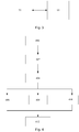
- Fig. 3 is a structural schematic diagram of a monitoring system according to an example of the present invention.
- the monitoring system comprises a wearable device 50 and a monitoring apparatus 60 in communicative connection with each other.
- the wearable device 50 is any one of the wearable devices 50 described above.
- Parameters associated with regions are preset in the monitoring apparatus 60.
- regions mean a site to be monitored; the site generally contains electromechanical equipment/robots etc. operating at high speed or other equipment posing a certain danger to entering staff.
- regions in a site may be divided into safe regions, regions requiring a warning and highly dangerous regions; the regions may be set by means of transverse and longitudinal position parameters of each region in the site.
- the monitoring apparatus 60 receives a sensing signal characterizing a wearer's position and sent by the wearable device 50, and thereby determines whether the position of the wearer is in a safe region, a region requiring a warning, or a highly dangerous region.
- the wearable device 50 does not comprise an indication module for issuing warning and other indication signals
- the monitoring apparatus 60 may issue a warning signal by itself, e.g. a display or voice indication, etc. A worker in a monitoring room can then immediately issue a human warning to the wearer.
- the monitoring apparatus 60 sends an indication signal to the wearable device 50, to be shown thereby. For example, when the wearer is in a safe region, the monitoring apparatus 60 sends a signal that the wearer is in a safe region to the wearable device 50; at this time, an optical indication module of the wearable device shows a green colour. When the wearer is in a region requiring a warning, the monitoring apparatus sends a warning signal that the wearer is in a region requiring a warning to the wearable device 50, and the optical indication module disposed on the wearable device 50 shows a yellow colour accordingly.
- a warning signal indicating that the wearer is in a highly dangerous region is sent to the wearable device 50, and the optical indication module shows a red colour accordingly.
- the signal transceivers simultaneously send the signal to audio indication modules (if the wearable device 50 comprises audio indication modules), so that they issue a warning in audio form that the wearer is in a dangerous region.
- a monitoring method for monitoring a site is also provided.
- Fig. 4 is a flow chart of the method.
- a wearable device is provided for an entering staff member to wear; the wearable device is set to comprise a position sensor and a signal transceiver.
- the wearable device senses position information of the entering staff member and sends the position information to the monitoring apparatus.
- the monitoring apparatus confirms whether the entering staff member is in a safe region, a region requiring a warning or a highly dangerous region on the basis of the position information received.
- step 406 When it is determined that the entering staff member is in a safe region, step 406 is entered: sending an indication signal for presence in a safe region to the wearable device.
- step 408 When it is determined that the entering staff member is in a region requiring a warning, step 408 is entered: sending an indication signal for presence in a region requiring a warning to the wearable device.
- step 410 When it is determined that the entering staff member is in a highly dangerous region, step 410 is entered: sending an indication signal for presence in a highly dangerous region to the wearable device.
- step 412 the wearable device indicates which type of region the entering staff member is currently in, according to the indication signal received.
- the wearable device may be the wearable device described with reference to fig. 1 or fig. 2 .
- the method shown as an example in fig. 4 may be executed in the monitoring system as shown in fig. 3 .
- the staff member's position in the site can be transmitted in real time to the monitoring apparatus.
- the monitoring apparatus determines, on the basis of the wearer's position, whether the region in which the wearer is located is a safe region, a region requiring a warning or a highly dangerous region.
- a warning is given in optical and/or audio form, and in the case of a high level of danger, a warning is preferably given in both optical form and audio form.
- the monitoring apparatus may also be configured to control electromechanical equipment or robots operating at high speed in the site, or other equipment posing a threat to entering staff, to stop operating.
- the monitoring apparatus may also be configured to adopt certain measures to help keep the entering staff member safe when the entering staff member (i.e. wearer) enters a highly dangerous region; the specific measures may be determined according to the actual environment of the monitored site.
- the wearable device has been described as being worn on the neck with reference to fig. 2 , but in actual applications, the wearable device could be a pair of spectacles, or could be a wearable device worn on the wrist or ankle.
- the first part is for example a spectacles arm while the second part is the other spectacles arm, and a part connected to the spectacles arms corresponds for example to the battery carrier.
Applications Claiming Priority (1)
| Application Number | Priority Date | Filing Date | Title |
|---|---|---|---|
| PCT/CN2016/101424 WO2018064792A1 (fr) | 2016-10-03 | 2016-10-03 | Dispositif vestimentaire et son système de surveillance |
Publications (2)
| Publication Number | Publication Date |
|---|---|
| EP3522126A1 true EP3522126A1 (fr) | 2019-08-07 |
| EP3522126A4 EP3522126A4 (fr) | 2019-10-23 |
Family
ID=61830749
Family Applications (1)
| Application Number | Title | Priority Date | Filing Date |
|---|---|---|---|
| EP16918126.0A Pending EP3522126A4 (fr) | 2016-10-03 | 2016-10-03 | Dispositif vestimentaire et son système de surveillance |
Country Status (4)
| Country | Link |
|---|---|
| US (1) | US10796551B2 (fr) |
| EP (1) | EP3522126A4 (fr) |
| CN (1) | CN109791720B (fr) |
| WO (1) | WO2018064792A1 (fr) |
Families Citing this family (3)
| Publication number | Priority date | Publication date | Assignee | Title |
|---|---|---|---|---|
| CN110802578B (zh) * | 2019-11-13 | 2022-08-30 | 吉林大学 | 一种可穿戴机器人上肢肢体的最大安全作业范围检测方法 |
| CA3164817A1 (fr) * | 2019-12-17 | 2021-06-24 | Johnson & Johnson Surgical Vision, Inc. | Systeme et procedes pour un mecanisme de capture de cassette pour des applications chirurgicales de phacoemulsification |
| CN113562624A (zh) * | 2021-07-05 | 2021-10-29 | 淮阴工学院 | 起重设备危险预警系统、起重设备及危险区域预警方法 |
Family Cites Families (16)
| Publication number | Priority date | Publication date | Assignee | Title |
|---|---|---|---|---|
| FR1349789A (fr) * | 1963-03-07 | 1964-01-17 | Agrostroj Prostejov Np | Dispositif de sécurité assurant l'arrêt automatique d'une machine |
| AU2001257217A1 (en) | 2000-04-26 | 2001-11-07 | Geowireless, Llc | Wearable location monitoring and communications system |
| JP3771892B2 (ja) * | 2002-10-28 | 2006-04-26 | 三菱重工業株式会社 | 危険情報伝達システム |
| CN201392588Y (zh) * | 2009-04-02 | 2010-01-27 | 孙考楠 | 随身携带的隐秘报警装置 |
| CN201600501U (zh) * | 2009-08-28 | 2010-10-06 | 中国科技开发院威海分院 | 无线立体视频眼镜 |
| WO2014015527A1 (fr) | 2012-07-27 | 2014-01-30 | 华为技术有限公司 | Procédé, appareil et système d'acquisition d'informations de pré-inscription |
| EP2698972B1 (fr) * | 2012-08-13 | 2017-06-14 | EMPORIA TELECOM GmbH & Co. KG | Dispositif d'alerte d'urgence à téléphone mobile |
| CN104054371A (zh) * | 2012-12-27 | 2014-09-17 | 华为技术有限公司 | 网络设备部署的方法、基站和网元管理设备 |
| CN104076380A (zh) * | 2014-07-21 | 2014-10-01 | 柳州治业科技有限公司 | 镜框式定位系统及其定位方法 |
| CN104346902A (zh) * | 2014-10-15 | 2015-02-11 | 瞿洪桂 | 一种具有报警功能的智能穿戴设备及系统 |
| CN104661308B (zh) | 2015-03-19 | 2018-07-20 | 国家电网公司 | 一种腰带式可穿戴室内移动定位终端 |
| CN104954981A (zh) | 2015-04-24 | 2015-09-30 | 广东小天才科技有限公司 | 一种确定安全位置的方法及装置 |
| CN105160807B (zh) | 2015-08-31 | 2017-07-28 | 湖南省普安建设工程有限公司 | 基于uwb的消防人员安全定位系统及定位方法 |
| CN205123722U (zh) | 2015-09-14 | 2016-03-30 | 广东工业大学 | 一种家庭可穿戴交互系统 |
| CN105701967B (zh) * | 2016-03-29 | 2018-07-27 | 北京小米移动软件有限公司 | 位置提醒方法和装置 |
| CN105872952B (zh) * | 2016-03-29 | 2019-12-27 | 北京小米移动软件有限公司 | 基于可穿戴设备的信息发送方法及装置 |
-
2016
- 2016-10-03 CN CN201680089814.4A patent/CN109791720B/zh active Active
- 2016-10-03 US US16/336,583 patent/US10796551B2/en active Active
- 2016-10-03 WO PCT/CN2016/101424 patent/WO2018064792A1/fr active Application Filing
- 2016-10-03 EP EP16918126.0A patent/EP3522126A4/fr active Pending
Also Published As
| Publication number | Publication date |
|---|---|
| US20190221100A1 (en) | 2019-07-18 |
| US10796551B2 (en) | 2020-10-06 |
| EP3522126A4 (fr) | 2019-10-23 |
| CN109791720B (zh) | 2022-01-25 |
| CN109791720A (zh) | 2019-05-21 |
| WO2018064792A1 (fr) | 2018-04-12 |
Similar Documents
| Publication | Publication Date | Title |
|---|---|---|
| US10796551B2 (en) | Wearable device and monitoring system comprising same | |
| US9673615B2 (en) | Isolator circuit | |
| EP3193797B1 (fr) | Adaptateur de communication d'outil de système de protection personnel | |
| EP3286910A1 (fr) | Système d'imagerie thermique | |
| EP3209925A1 (fr) | Vêtement de sécurité | |
| US8630758B2 (en) | Method and apparatus for safety protocol verification, control and management | |
| CN110623361A (zh) | 一种智能安全帽及监测方法 | |
| CN104083831A (zh) | 一种具有定位功能的智能疏散指示系统及疏散方法 | |
| CN202662114U (zh) | 声光报警标识牌 | |
| US9214076B2 (en) | Firefighter's safety monitoring and alarm | |
| CN108877159B (zh) | 接近感测和警示的方法和系统 | |
| US9767968B2 (en) | Method and device for protecting persons in the vicinity of an HF field-emitting device | |
| US9825697B2 (en) | Collective remote signaling device | |
| EP3159263B1 (fr) | Ensemble d'affichage, utilisation d'un ensemble d'affichage et ensemble d'aéronef comportant un tel ensemble d'affichage | |
| KR102545574B1 (ko) | 중장비용 위험경고 시스템 | |
| US20190213863A1 (en) | Electronic personal dosimeter smart accessory system | |
| US11568752B2 (en) | Gateway retrieval alert device for aircraft pushback operations | |
| US20230353972A1 (en) | System for warning about entering a restricted area | |
| AU2015101024A4 (en) | Isolator circuit | |
| KR20190113246A (ko) | 눈 보호구를 이용한 시각적 위험 알림 시스템 및 방법 | |
| CN105877737A (zh) | 基于车辆把手的心电监控装置 | |
| KR20140054999A (ko) | 비상등 자체에 고장을 알수있는 비상등 | |
| CN110786572A (zh) | 劳保服系统 | |
| ITBO20130175A1 (it) | Sistema e metodo di sicurezza e protezione di una o più persone. | |
| ITVI20010200A1 (it) | Sistema satellitare per individuare e soccorrere persone in caso di incidente attentato e/o pericolo di vita |
Legal Events
| Date | Code | Title | Description |
|---|---|---|---|
| STAA | Information on the status of an ep patent application or granted ep patent |
Free format text: STATUS: THE INTERNATIONAL PUBLICATION HAS BEEN MADE |
|
| PUAI | Public reference made under article 153(3) epc to a published international application that has entered the european phase |
Free format text: ORIGINAL CODE: 0009012 |
|
| STAA | Information on the status of an ep patent application or granted ep patent |
Free format text: STATUS: REQUEST FOR EXAMINATION WAS MADE |
|
| 17P | Request for examination filed |
Effective date: 20190503 |
|
| AK | Designated contracting states |
Kind code of ref document: A1 Designated state(s): AL AT BE BG CH CY CZ DE DK EE ES FI FR GB GR HR HU IE IS IT LI LT LU LV MC MK MT NL NO PL PT RO RS SE SI SK SM TR |
|
| AX | Request for extension of the european patent |
Extension state: BA ME |
|
| A4 | Supplementary search report drawn up and despatched |
Effective date: 20190925 |
|
| RIC1 | Information provided on ipc code assigned before grant |
Ipc: G08B 21/02 20060101AFI20190919BHEP Ipc: F16P 3/14 20060101ALI20190919BHEP Ipc: G08B 21/04 20060101ALI20190919BHEP |
|
| DAV | Request for validation of the european patent (deleted) | ||
| DAX | Request for extension of the european patent (deleted) | ||
| RAP1 | Party data changed (applicant data changed or rights of an application transferred) |
Owner name: ROBERT BOSCH GMBH |
|
| STAA | Information on the status of an ep patent application or granted ep patent |
Free format text: STATUS: EXAMINATION IS IN PROGRESS |
|
| 17Q | First examination report despatched |
Effective date: 20220615 |