EP3521963B1 - Densité de point d'échantillonnage de ligne de référence réglable dynamiquement pour véhicules autonomes - Google Patents
Densité de point d'échantillonnage de ligne de référence réglable dynamiquement pour véhicules autonomes Download PDFInfo
- Publication number
- EP3521963B1 EP3521963B1 EP19152965.0A EP19152965A EP3521963B1 EP 3521963 B1 EP3521963 B1 EP 3521963B1 EP 19152965 A EP19152965 A EP 19152965A EP 3521963 B1 EP3521963 B1 EP 3521963B1
- Authority
- EP
- European Patent Office
- Prior art keywords
- adv
- reference points
- distance
- sampling distance
- sampling
- Prior art date
- Legal status (The legal status is an assumption and is not a legal conclusion. Google has not performed a legal analysis and makes no representation as to the accuracy of the status listed.)
- Active
Links
- 238000005070 sampling Methods 0.000 title claims description 126
- 238000004422 calculation algorithm Methods 0.000 claims description 38
- 238000000034 method Methods 0.000 claims description 28
- 238000012545 processing Methods 0.000 claims description 25
- 230000015654 memory Effects 0.000 claims description 18
- 230000006870 function Effects 0.000 claims description 11
- 230000007423 decrease Effects 0.000 claims description 4
- 230000000750 progressive effect Effects 0.000 claims description 2
- 230000008447 perception Effects 0.000 description 27
- 238000010586 diagram Methods 0.000 description 13
- 238000004891 communication Methods 0.000 description 11
- 230000004807 localization Effects 0.000 description 8
- 230000008569 process Effects 0.000 description 8
- 230000001133 acceleration Effects 0.000 description 6
- 230000002085 persistent effect Effects 0.000 description 5
- 238000012517 data analytics Methods 0.000 description 4
- 230000003287 optical effect Effects 0.000 description 4
- 230000001413 cellular effect Effects 0.000 description 3
- 230000008859 change Effects 0.000 description 3
- 230000000694 effects Effects 0.000 description 3
- 230000033001 locomotion Effects 0.000 description 3
- 238000010801 machine learning Methods 0.000 description 3
- 230000005540 biological transmission Effects 0.000 description 2
- 238000013461 design Methods 0.000 description 2
- 238000005516 engineering process Methods 0.000 description 2
- 230000005291 magnetic effect Effects 0.000 description 2
- 230000002093 peripheral effect Effects 0.000 description 2
- 230000009471 action Effects 0.000 description 1
- 238000003491 array Methods 0.000 description 1
- 230000004888 barrier function Effects 0.000 description 1
- 238000004364 calculation method Methods 0.000 description 1
- 230000010267 cellular communication Effects 0.000 description 1
- 230000000295 complement effect Effects 0.000 description 1
- 238000004590 computer program Methods 0.000 description 1
- 238000010276 construction Methods 0.000 description 1
- 230000001419 dependent effect Effects 0.000 description 1
- 238000001514 detection method Methods 0.000 description 1
- 230000003467 diminishing effect Effects 0.000 description 1
- 235000019800 disodium phosphate Nutrition 0.000 description 1
- 238000009429 electrical wiring Methods 0.000 description 1
- 229910000078 germane Inorganic materials 0.000 description 1
- 238000009499 grossing Methods 0.000 description 1
- 238000003384 imaging method Methods 0.000 description 1
- 230000003993 interaction Effects 0.000 description 1
- 238000005259 measurement Methods 0.000 description 1
- 230000007246 mechanism Effects 0.000 description 1
- 229910044991 metal oxide Inorganic materials 0.000 description 1
- 150000004706 metal oxides Chemical class 0.000 description 1
- 238000012986 modification Methods 0.000 description 1
- 230000004048 modification Effects 0.000 description 1
- 230000008450 motivation Effects 0.000 description 1
- 230000009467 reduction Effects 0.000 description 1
- 230000010076 replication Effects 0.000 description 1
- 230000004044 response Effects 0.000 description 1
- 230000004043 responsiveness Effects 0.000 description 1
- 239000004065 semiconductor Substances 0.000 description 1
- 230000035945 sensitivity Effects 0.000 description 1
- 239000007787 solid Substances 0.000 description 1
- 230000003068 static effect Effects 0.000 description 1
- 239000000126 substance Substances 0.000 description 1
- 238000010897 surface acoustic wave method Methods 0.000 description 1
- 230000001360 synchronised effect Effects 0.000 description 1
Images


Classifications
-
- G—PHYSICS
- G05—CONTROLLING; REGULATING
- G05D—SYSTEMS FOR CONTROLLING OR REGULATING NON-ELECTRIC VARIABLES
- G05D1/00—Control of position, course or altitude of land, water, air, or space vehicles, e.g. automatic pilot
- G05D1/02—Control of position or course in two dimensions
- G05D1/021—Control of position or course in two dimensions specially adapted to land vehicles
- G05D1/0231—Control of position or course in two dimensions specially adapted to land vehicles using optical position detecting means
- G05D1/0238—Control of position or course in two dimensions specially adapted to land vehicles using optical position detecting means using obstacle or wall sensors
- G05D1/024—Control of position or course in two dimensions specially adapted to land vehicles using optical position detecting means using obstacle or wall sensors in combination with a laser
-
- G—PHYSICS
- G05—CONTROLLING; REGULATING
- G05D—SYSTEMS FOR CONTROLLING OR REGULATING NON-ELECTRIC VARIABLES
- G05D1/00—Control of position, course or altitude of land, water, air, or space vehicles, e.g. automatic pilot
- G05D1/02—Control of position or course in two dimensions
- G05D1/021—Control of position or course in two dimensions specially adapted to land vehicles
- G05D1/0212—Control of position or course in two dimensions specially adapted to land vehicles with means for defining a desired trajectory
-
- B—PERFORMING OPERATIONS; TRANSPORTING
- B60—VEHICLES IN GENERAL
- B60W—CONJOINT CONTROL OF VEHICLE SUB-UNITS OF DIFFERENT TYPE OR DIFFERENT FUNCTION; CONTROL SYSTEMS SPECIALLY ADAPTED FOR HYBRID VEHICLES; ROAD VEHICLE DRIVE CONTROL SYSTEMS FOR PURPOSES NOT RELATED TO THE CONTROL OF A PARTICULAR SUB-UNIT
- B60W30/00—Purposes of road vehicle drive control systems not related to the control of a particular sub-unit, e.g. of systems using conjoint control of vehicle sub-units, or advanced driver assistance systems for ensuring comfort, stability and safety or drive control systems for propelling or retarding the vehicle
- B60W30/14—Adaptive cruise control
-
- B—PERFORMING OPERATIONS; TRANSPORTING
- B60—VEHICLES IN GENERAL
- B60W—CONJOINT CONTROL OF VEHICLE SUB-UNITS OF DIFFERENT TYPE OR DIFFERENT FUNCTION; CONTROL SYSTEMS SPECIALLY ADAPTED FOR HYBRID VEHICLES; ROAD VEHICLE DRIVE CONTROL SYSTEMS FOR PURPOSES NOT RELATED TO THE CONTROL OF A PARTICULAR SUB-UNIT
- B60W30/00—Purposes of road vehicle drive control systems not related to the control of a particular sub-unit, e.g. of systems using conjoint control of vehicle sub-units, or advanced driver assistance systems for ensuring comfort, stability and safety or drive control systems for propelling or retarding the vehicle
- B60W30/08—Active safety systems predicting or avoiding probable or impending collision or attempting to minimise its consequences
- B60W30/095—Predicting travel path or likelihood of collision
-
- B—PERFORMING OPERATIONS; TRANSPORTING
- B60—VEHICLES IN GENERAL
- B60W—CONJOINT CONTROL OF VEHICLE SUB-UNITS OF DIFFERENT TYPE OR DIFFERENT FUNCTION; CONTROL SYSTEMS SPECIALLY ADAPTED FOR HYBRID VEHICLES; ROAD VEHICLE DRIVE CONTROL SYSTEMS FOR PURPOSES NOT RELATED TO THE CONTROL OF A PARTICULAR SUB-UNIT
- B60W60/00—Drive control systems specially adapted for autonomous road vehicles
- B60W60/001—Planning or execution of driving tasks
-
- G—PHYSICS
- G01—MEASURING; TESTING
- G01C—MEASURING DISTANCES, LEVELS OR BEARINGS; SURVEYING; NAVIGATION; GYROSCOPIC INSTRUMENTS; PHOTOGRAMMETRY OR VIDEOGRAMMETRY
- G01C21/00—Navigation; Navigational instruments not provided for in groups G01C1/00 - G01C19/00
- G01C21/26—Navigation; Navigational instruments not provided for in groups G01C1/00 - G01C19/00 specially adapted for navigation in a road network
- G01C21/34—Route searching; Route guidance
- G01C21/3407—Route searching; Route guidance specially adapted for specific applications
-
- G—PHYSICS
- G01—MEASURING; TESTING
- G01C—MEASURING DISTANCES, LEVELS OR BEARINGS; SURVEYING; NAVIGATION; GYROSCOPIC INSTRUMENTS; PHOTOGRAMMETRY OR VIDEOGRAMMETRY
- G01C21/00—Navigation; Navigational instruments not provided for in groups G01C1/00 - G01C19/00
- G01C21/26—Navigation; Navigational instruments not provided for in groups G01C1/00 - G01C19/00 specially adapted for navigation in a road network
- G01C21/34—Route searching; Route guidance
- G01C21/3446—Details of route searching algorithms, e.g. Dijkstra, A*, arc-flags, using precalculated routes
-
- G—PHYSICS
- G05—CONTROLLING; REGULATING
- G05D—SYSTEMS FOR CONTROLLING OR REGULATING NON-ELECTRIC VARIABLES
- G05D1/00—Control of position, course or altitude of land, water, air, or space vehicles, e.g. automatic pilot
- G05D1/02—Control of position or course in two dimensions
- G05D1/021—Control of position or course in two dimensions specially adapted to land vehicles
- G05D1/0231—Control of position or course in two dimensions specially adapted to land vehicles using optical position detecting means
- G05D1/0246—Control of position or course in two dimensions specially adapted to land vehicles using optical position detecting means using a video camera in combination with image processing means
-
- G—PHYSICS
- G05—CONTROLLING; REGULATING
- G05D—SYSTEMS FOR CONTROLLING OR REGULATING NON-ELECTRIC VARIABLES
- G05D1/00—Control of position, course or altitude of land, water, air, or space vehicles, e.g. automatic pilot
- G05D1/02—Control of position or course in two dimensions
- G05D1/021—Control of position or course in two dimensions specially adapted to land vehicles
- G05D1/0268—Control of position or course in two dimensions specially adapted to land vehicles using internal positioning means
- G05D1/0274—Control of position or course in two dimensions specially adapted to land vehicles using internal positioning means using mapping information stored in a memory device
-
- G—PHYSICS
- G08—SIGNALLING
- G08G—TRAFFIC CONTROL SYSTEMS
- G08G1/00—Traffic control systems for road vehicles
- G08G1/09—Arrangements for giving variable traffic instructions
- G08G1/0962—Arrangements for giving variable traffic instructions having an indicator mounted inside the vehicle, e.g. giving voice messages
- G08G1/0968—Systems involving transmission of navigation instructions to the vehicle
- G08G1/096805—Systems involving transmission of navigation instructions to the vehicle where the transmitted instructions are used to compute a route
- G08G1/096827—Systems involving transmission of navigation instructions to the vehicle where the transmitted instructions are used to compute a route where the route is computed onboard
-
- G—PHYSICS
- G08—SIGNALLING
- G08G—TRAFFIC CONTROL SYSTEMS
- G08G1/00—Traffic control systems for road vehicles
- G08G1/09—Arrangements for giving variable traffic instructions
- G08G1/0962—Arrangements for giving variable traffic instructions having an indicator mounted inside the vehicle, e.g. giving voice messages
- G08G1/0968—Systems involving transmission of navigation instructions to the vehicle
- G08G1/096833—Systems involving transmission of navigation instructions to the vehicle where different aspects are considered when computing the route
- G08G1/096844—Systems involving transmission of navigation instructions to the vehicle where different aspects are considered when computing the route where the complete route is dynamically recomputed based on new data
-
- G—PHYSICS
- G08—SIGNALLING
- G08G—TRAFFIC CONTROL SYSTEMS
- G08G1/00—Traffic control systems for road vehicles
- G08G1/16—Anti-collision systems
- G08G1/161—Decentralised systems, e.g. inter-vehicle communication
- G08G1/163—Decentralised systems, e.g. inter-vehicle communication involving continuous checking
-
- G—PHYSICS
- G08—SIGNALLING
- G08G—TRAFFIC CONTROL SYSTEMS
- G08G1/00—Traffic control systems for road vehicles
- G08G1/16—Anti-collision systems
- G08G1/165—Anti-collision systems for passive traffic, e.g. including static obstacles, trees
-
- G—PHYSICS
- G08—SIGNALLING
- G08G—TRAFFIC CONTROL SYSTEMS
- G08G1/00—Traffic control systems for road vehicles
- G08G1/16—Anti-collision systems
- G08G1/166—Anti-collision systems for active traffic, e.g. moving vehicles, pedestrians, bikes
-
- G—PHYSICS
- G06—COMPUTING; CALCULATING OR COUNTING
- G06T—IMAGE DATA PROCESSING OR GENERATION, IN GENERAL
- G06T2207/00—Indexing scheme for image analysis or image enhancement
- G06T2207/30—Subject of image; Context of image processing
- G06T2207/30241—Trajectory
Definitions
- Embodiments of the present disclosure relate generally to operating autonomous vehicles. More particularly, embodiments of the disclosure relate to dynamically adjusted reference line sampling point density for autonomous driving vehicles (ADVs).
- ADVs autonomous driving vehicles
- Vehicles operating in an autonomous mode can relieve occupants, especially the driver, from some driving-related responsibilities.
- the vehicle can navigate to various locations using onboard sensors, allowing the vehicle to travel with minimal human interaction or in some cases without any passengers.
- Vehicles can operate in an autonomous mode by a planned driving trajectory.
- a planned driving trajectory is generated by an ADV's planning module relying on "reference lines".
- a reference line is a smooth line on a geometric word map. Reference lines are represented by a set of points along a road curve. A typical 200 meter road curve uses 1000 points for a reference line.
- the computation time for many algorithms, such as reference line projections and driving trajectory decision and planning, are directly related to the number of points or density of a reference line.
- US 9 804 603 B1 discloses the following: improved vehicle guidance systems and methods are provided; a generated guidance curve approximates a vehicle trajectory path comprising a set of two-dimensional reference points; the guidance curve is based on a summed and weighted radial basis functions; weighting is associated with coefficients calculated using linear least-squares regression to minimize approximation error between the guidance curve and the vehicle trajectory path; guidance instructions are based, at least in part, on a nearest location point, and a tangent direction and curvature of the guidance curve at the nearest location point; the controller autonomously guides the vehicle along the guidance curve.
- a computer-implemented method to generate a driving trajectory with progressive sampling distance for an autonomous driving vehicle includes: receiving a first set of reference points based on a map and a route information, the first set of reference points representing a reference line in which the ADV is to follow; selecting a second set of reference points along the reference line corresponding to the first set of reference points, including iteratively performing, selecting a current reference point from the first set of reference points; determining a sampling distance along the first set of reference points based on the currently selected reference point using a nonlinear algorithm; and selecting a next reference point along the first set of reference points based on the determined sampling distance such that a density of the selected reference points closer to the ADV is higher than a density of the selected reference points farther away from the ADV; and planning a trajectory for the ADV using the second set of reference points to control the ADV.
- ADV autonomous driving vehicle
- a non-transitory machine-readable medium having instructions stored therein.
- the instructions when executed by a processor, cause the processor to perform operations, the operations including: receiving a first set of reference points based on a map and a route information, the first set of reference points representing a reference line in which the ADV is to follow; selecting a second set of reference points along the reference line corresponding to the first set of reference points, including iteratively performing, selecting a current reference point from the first set of reference points; determining a sampling distance along the first set of reference points based on the currently selected reference point using a nonlinear algorithm; and selecting a next reference point along the first set of reference points based on the determined sampling distance such that a density of the selected reference points closer to the ADV is higher than a density of the selected reference points farther away from the ADV; and planning a trajectory for the ADV using the second set of reference points to control the ADV.
- a data processing system includes: one or more processors; and a memory coupled to the one or more processors to store instructions, which when executed by the one or more processors, cause the processor to perform operations, the operations including receiving a first set of reference points based on a map and a route information, the first set of reference points representing a reference line in which the ADV is to follow; selecting a second set of reference points along the reference line corresponding to the first set of reference points, including iteratively performing, selecting a current reference point from the first set of reference points; determining a sampling distance along the first set of reference points based on the currently selected reference point using a nonlinear algorithm; and selecting a next reference point along the first set of reference points based on the determined sampling distance such that a density of the selected reference points closer to the ADV is higher than a density of the selected reference points farther away from the ADV; and planning a trajectory for the ADV using the second set of reference points to control the ADV.
- a system dynamically adjusts a reference line sampling point density.
- the system receives a first set of reference points based on a map and a route information, the first plurality of reference points representing a reference line in which the ADV is to follow.
- the system selects a second set of reference points along the reference line, including iteratively performing, selecting a current reference point from the first set of reference points, determining a sampling distance along the first set of reference points based on the currently selected reference point using a nonlinear algorithm, and selecting a next reference point based on the determined sampling distance such that a density of the second set of reference points closer to the ADV is higher than a density of the selected reference points farther away from the ADV.
- the system plans a trajectory for the ADV using the second set of reference points to control the ADV.
- FIG. 1 is a block diagram illustrating an autonomous vehicle network configuration according to one embodiment of the disclosure.
- network configuration 100 includes autonomous vehicle 101 that may be communicatively coupled to one or more servers 103-104 over a network 102. Although there is one autonomous vehicle shown, multiple autonomous vehicles can be coupled to each other and/or coupled to servers 103-104 over network 102.
- Network 102 may be any type of networks such as a local area network (LAN), a wide area network (WAN) such as the Internet, a cellular network, a satellite network, or a combination thereof, wired or wireless.
- Server(s) 103-104 may be any kind of servers or a cluster of servers, such as Web or cloud servers, application servers, backend servers, or a combination thereof.
- Servers 103-104 may be data analytics servers, content servers, traffic information servers, map and point of interest (MPOI) severs, or location servers, etc.
- MPOI map and point of interest
- An autonomous vehicle refers to a vehicle that can be configured to in an autonomous mode in which the vehicle navigates through an environment with little or no input from a driver.
- Such an autonomous vehicle can include a sensor system having one or more sensors that are configured to detect information about the environment in which the vehicle operates. The vehicle and its associated controller(s) use the detected information to navigate through the environment.
- Autonomous vehicle 101 can operate in a manual mode, a full autonomous mode, or a partial autonomous mode.
- autonomous vehicle 101 includes, but is not limited to, perception and planning system 110, vehicle control system 111, wireless communication system 112, user interface system 113, and sensor system 115.
- Autonomous vehicle 101 may further include certain common components included in ordinary vehicles, such as, an engine, wheels, steering wheel, transmission, etc., which may be controlled by vehicle control system 111 and/or perception and planning system 110 using a variety of communication signals and/or commands, such as, for example, acceleration signals or commands, deceleration signals or commands, steering signals or commands, braking signals or commands, etc.
- Components 110-115 may be communicatively coupled to each other via an interconnect, a bus, a network, or a combination thereof.
- components 110-115 may be communicatively coupled to each other via a controller area network (CAN) bus.
- CAN controller area network
- a CAN bus is a vehicle bus standard designed to allow microcontrollers and devices to communicate with each other in applications without a host computer. It is a message-based protocol, designed originally for multiplex electrical wiring within automobiles, but is also used in many other contexts.
- sensor system 115 includes, but it is not limited to, one or more cameras 211, global positioning system (GPS) unit 212, inertial measurement unit (IMU) 213, radar unit 214, and a light detection and range (LIDAR) unit 215.
- GPS system 212 may include a transceiver operable to provide information regarding the position of the autonomous vehicle.
- IMU unit 213 may sense position and orientation changes of the autonomous vehicle based on inertial acceleration.
- Radar unit 214 may represent a system that utilizes radio signals to sense objects within the local environment of the autonomous vehicle. In some embodiments, in addition to sensing objects, radar unit 214 may additionally sense the speed and/or heading of the objects.
- LIDAR unit 215 may sense objects in the environment in which the autonomous vehicle is located using lasers.
- LIDAR unit 215 could include one or more laser sources, a laser scanner, and one or more detectors, among other system components.
- Cameras 211 may include one or more devices to capture images of the environment surrounding the autonomous vehicle. Cameras 211 may be still cameras and/or video cameras. A camera may be mechanically movable, for example, by mounting the camera on a rotating and/or tilting a platform.
- Sensor system 115 may further include other sensors, such as, a sonar sensor, an infrared sensor, a steering sensor, a throttle sensor, a braking sensor, and an audio sensor (e.g., microphone).
- An audio sensor may be configured to capture sound from the environment surrounding the autonomous vehicle.
- a steering sensor may be configured to sense the steering angle of a steering wheel, wheels of the vehicle, or a combination thereof.
- a throttle sensor and a braking sensor sense the throttle position and braking position of the vehicle, respectively. In some situations, a throttle sensor and a braking sensor may be integrated as an integrated throttle/braking sensor.
- vehicle control system 111 includes, but is not limited to, steering unit 201, throttle unit 202 (also referred to as an acceleration unit), and braking unit 203.
- Steering unit 201 is to adjust the direction or heading of the vehicle.
- Throttle unit 202 is to control the speed of the motor or engine that in turn control the speed and acceleration of the vehicle.
- Braking unit 203 is to decelerate the vehicle by providing friction to slow the wheels or tires of the vehicle. Note that the components as shown in Figure 2 may be implemented in hardware, software, or a combination thereof.
- wireless communication system 112 is to allow communication between autonomous vehicle 101 and external systems, such as devices, sensors, other vehicles, etc.
- wireless communication system 112 can wirelessly communicate with one or more devices directly or via a communication network, such as servers 103-104 over network 102.
- Wireless communication system 112 can use any cellular communication network or a wireless local area network (WLAN), e.g., using WiFi to communicate with another component or system.
- Wireless communication system 112 could communicate directly with a device (e.g., a mobile device of a passenger, a display device, a speaker within vehicle 101), for example, using an infrared link, Bluetooth, etc.
- User interface system 113 may be part of peripheral devices implemented within vehicle 101 including, for example, a keyword, a touch screen display device, a microphone, and a speaker, etc.
- Perception and planning system 110 includes the necessary hardware (e.g., processor(s), memory, storage) and software (e.g., operating system, planning and routing programs) to receive information from sensor system 115, control system 111, wireless communication system 112, and/or user interface system 113, process the received information, plan a route or path from a starting point to a destination point, and then drive vehicle 101 based on the planning and control information.
- Perception and planning system 110 may be integrated with vehicle control system 111.
- Perception and planning system 110 obtains the trip related data.
- perception and planning system 110 may obtain location and route information from an MPOI server, which may be a part of servers 103-104.
- the location server provides location services and the MPOI server provides map services and the POIs of certain locations.
- such location and MPOI information may be cached locally in a persistent storage device of perception and planning system 110.
- perception and planning system 110 may also obtain real-time traffic information from a traffic information system or server (TIS).
- TIS traffic information system
- servers 103-104 may be operated by a third party entity. Alternatively, the functionalities of servers 103-104 may be integrated with perception and planning system 110.
- MPOI information MPOI information
- location information e.g., obstacles, objects, nearby vehicles
- perception and planning system 110 can plan an optimal route and drive vehicle 101, for example, via control system 111, according to the planned route to reach the specified destination safely and efficiently.
- Server 103 may be a data analytics system to perform data analytics services for a variety of clients.
- data analytics system 103 includes data collector 121 and machine learning engine 122.
- Data collector 121 collects driving statistics 123 from a variety of vehicles, either autonomous vehicles or regular vehicles driven by human drivers.
- Driving statistics 123 include information indicating the driving commands (e.g., throttle, brake, steering commands) issued and responses of the vehicles (e.g., speeds, accelerations, decelerations, directions) captured by sensors of the vehicles at different points in time.
- Driving statistics 123 may further include information describing the driving environments at different points in time, such as, for example, routes (including starting and destination locations), MPOIs, road conditions, weather conditions, etc.
- machine learning engine 122 Based on driving statistics 123, machine learning engine 122 generates or trains a set of rules, algorithms, and/or models 124 for a variety of purposes.
- algorithms /model 124 may include a sampling model or algorithm that can dynamically adjust a reference line sampling point density.
- the sampling model can include minimum sampling distances, maximum sampling distances, and one or more sampling algorithms to modify a reference line sampling point density.
- the sampling model can be uploaded onto the autonomous driving vehicle to be used to dynamically adjust a reference line point density of a reference line at real time.
- FIGS 3A and 3B are block diagrams illustrating an example of a perception and planning system used with an autonomous vehicle according to one embodiment.
- System 300 may be implemented as a part of autonomous vehicle 101 of Figure 1 including, but is not limited to, perception and planning system 110, control system 111, and sensor system 115.
- perception and planning system 110 includes, but is not limited to, localization module 301, perception module 302, prediction module 303, decision module 304, planning module 305, control module 306, routing/sampling module 307, and reference line generator 309.
- modules 301-309 may be implemented in software, hardware, or a combination thereof. For example, these modules may be installed in persistent storage device 352, loaded into memory 351, and executed by one or more processors (not shown). Note that some or all of these modules may be communicatively coupled to or integrated with some or all modules of vehicle control system 111 of Figure 2 . Some of modules 301-309 may be integrated together as an integrated module. For example, routing/sampling module 307 and reference line generator 309 may be integrated as a single module.
- Localization module 301 determines a current location of autonomous vehicle 300 (e.g., leveraging GPS unit 212) and manages any data related to a trip or route of a user.
- Localization module 301 (also referred to as a map and route module) manages any data related to a trip or route of a user.
- a user may log in and specify a starting location and a destination of a trip, for example, via a user interface.
- Localization module 301 communicates with other components of autonomous vehicle 300, such as map and route information 311, to obtain the trip related data.
- localization module 301 may obtain location and route information from a location server and a map and POI (MPOI) server.
- MPOI map and POI
- a location server provides location services and an MPOI server provides map services and the POIs of certain locations, which may be cached as part of map and route information 311. While autonomous vehicle 300 is moving along the route, localization module 301 may also obtain real-time traffic information from a traffic information system or server.
- a perception of the surrounding environment is determined by perception module 302.
- the perception information may represent what an ordinary driver would perceive surrounding a vehicle in which the driver is driving.
- the perception can include the lane configuration (e.g., straight or curve lanes), traffic light signals, a relative position of another vehicle, a pedestrian, a building, crosswalk, or other traffic related signs (e.g., stop signs, yield signs), etc., for example, in a form of an object.
- Perception module 302 may include a computer vision system or functionalities of a computer vision system to process and analyze images captured by one or more cameras in order to identify objects and/or features in the environment of autonomous vehicle.
- the objects can include traffic signals, road way boundaries, other vehicles, pedestrians, and/or obstacles, etc.
- the computer vision system may use an object recognition algorithm, video tracking, and other computer vision techniques.
- the computer vision system can map an environment, track objects, and estimate the speed of objects, etc.
- Perception module 302 can also detect objects based on other sensors data provided by other sensors such as a radar and/or LIDAR
- prediction module 303 predicts how the object will behave under the circumstances. The prediction is performed based on the perception data perceiving the driving environment at the point in time in view of a set of map/rout information 311 and traffic rules 312. For example, if the object is a vehicle at an opposing direction and the current driving environment includes an intersection, prediction module 303 will predict whether the vehicle will likely move straight forward or make a turn. If the perception data indicates that the intersection has no traffic light, prediction module 303 may predict that the vehicle may have to fully stop prior to enter the intersection. If the perception data indicates that the vehicle is currently at a left-turn only lane or a right-turn only lane, prediction module 303 may predict that the vehicle will more likely make a left turn or right turn respectively.
- decision module 304 makes a decision regarding how to handle the object. For example, for a particular object (e.g., another vehicle in a crossing route) as well as its metadata describing the object (e.g., a speed, direction, turning angle), decision module 304 decides how to encounter the object (e.g., overtake, yield, stop, pass). Decision module 304 may make such decisions according to a set of rules such as traffic rules or driving rules 312, which may be stored in persistent storage device 352.
- rules such as traffic rules or driving rules 312, which may be stored in persistent storage device 352.
- planning module 305 plans a path or route for the autonomous vehicle, as well as driving parameters (e.g., distance, speed, and/or turning angle). That is, for a given object, decision module 304 decides what to do with the object, while planning module 305 determines how to do it. For example, for a given object, decision module 304 may decide to pass the object, while planning module 305 may determine whether to pass on the left side or right side of the object.
- Planning and control data is generated by planning module 305 including information describing how vehicle 300 would move in a next moving cycle (e.g., next route/path segment). For example, the planning and control data may instruct vehicle 300 to move 10 meters at a speed of 30 mile per hour (mph), then change to a right lane at the speed of 25 mph.
- control module 306 controls and drives the autonomous vehicle, by sending proper commands or signals to vehicle control system 111, according to a route or path defined by the planning and control data.
- the planning and control data include sufficient information to drive the vehicle from a first point to a second point of a route or path using appropriate vehicle settings or driving parameters (e.g., throttle, braking, and turning commands) at different points in time along the path or route.
- the planning phase is performed in a number of planning cycles, also referred to as command cycles, such as, for example, in every time interval of 100 milliseconds (ms).
- command cycles such as, for example, in every time interval of 100 milliseconds (ms).
- one or more control commands will be issued based on the planning and control data. That is, for every 100 ms, planning module 305 plans a next route segment or path segment, for example, including a target position and the time required for the ADV to reach the target position. Alternatively, planning module 305 may further specify the specific speed, direction, and/or steering angle, etc.
- planning module 305 plans a route segment or path segment for the next predetermined period of time such as 5 seconds.
- planning module 305 plans a target position for the current cycle (e.g., next 5 seconds) based on a target position planned in a previous cycle.
- Control module 306 then generates one or more control commands (e.g., throttle, brake, steering control commands) based on the planning and control data of the current cycle.
- control commands e.g., throttle, brake, steering control commands
- Decision module 304 and planning module 305 may be integrated as an integrated module.
- Decision module 304/planning module 305 may include a navigation system or functionalities of a navigation system to determine a driving path for the autonomous vehicle.
- the navigation system may determine a series of speeds and directional headings to effect movement of the autonomous vehicle along a path that substantially avoids perceived obstacles while generally advancing the autonomous vehicle along a roadway-based path leading to an ultimate destination.
- the destination may be set according to user inputs via user interface system 113.
- the navigation system may update the driving path dynamically while the autonomous vehicle is in operation.
- the navigation system can incorporate data from a GPS system and one or more maps so as to determine the driving path for the autonomous vehicle.
- Decision module 304/planning module 305 may further include a collision avoidance system or functionalities of a collision avoidance system to identify, evaluate, and avoid or otherwise negotiate potential obstacles in the environment of the autonomous vehicle.
- the collision avoidance system may effect changes in the navigation of the autonomous vehicle by operating one or more subsystems in control system 111 to undertake swerving maneuvers, turning maneuvers, braking maneuvers, etc.
- the collision avoidance system may automatically determine feasible obstacle avoidance maneuvers on the basis of surrounding traffic patterns, road conditions, etc.
- the collision avoidance system may be configured such that a swerving maneuver is not undertaken when other sensor systems detect vehicles, construction barriers, etc. in the region adjacent the autonomous vehicle that would be swerved into.
- the collision avoidance system may automatically select the maneuver that is both available and maximizes safety of occupants of the autonomous vehicle.
- the collision avoidance system may select an avoidance maneuver predicted to cause the least amount of acceleration in a passenger cabin of the autonomous vehicle.
- Routing module 307 can generate reference lines, for example, from map information such as information of road segments, vehicular lanes of road segments, and distances from lanes to curb.
- a road can be divided into sections or segments ⁇ A, B, and C ⁇ to denote three road segments.
- Three lanes of road segment A can be enumerated ⁇ A1, A2, and A3 ⁇ .
- a reference line is generated by generating reference points of uniform density along the reference line.
- routing module 307 can connect midpoints of two opposing curbs or extremities of the vehicular lane provided by a map data.
- routing module 307 can calculate the reference points by selecting a subset of the collected data points within a predetermined proximity of the vehicular lane and applying a smoothing function to the midpoints in view of the subset of collected data points.
- reference line generator 309 may generate a reference line by interpolating the reference points such that the generated reference line is used as a reference line for controlling ADVs on the vehicular lane.
- a reference points table and a road segments table representing the reference lines are downloaded in real-time to ADVs such that the ADVs can generate reference lines from the reference points table and the road segments table based on the ADVs' geographical location and driving direction.
- an ADV can generate a reference line by requesting routing service for a path segment by a path segment identifier representing an upcoming road section ahead and/or based on the ADV's GPS location.
- a routing service can return to the ADV reference points table containing reference points for all lanes of road segments of interest.
- ADV can look up reference points for a lane for a path segment to generate a reference line for controlling the ADV on the vehicular lane.
- sampling module 307 can determine a minimum sampling distance and a maximum sampling distance for a length of road to dynamically adjust a density of the generated reference line for a reference line with a non-uniform line density. For example, sampling module 307 can apply a sampling algorithm (as part of sampling algorithm/model 313) to dynamically adjust a density of the generated reference line to reduce the number of reference points of the reference line based on availability of computational resources or to satisfy some objective requirements.
- a sampling algorithm as part of sampling algorithm/model 313
- sampling module 307 may receive a request from perception and planning system 110 (by way of settings change via a user interface, or an update downloaded to the ADV via server 104) to reduce a reference point density by about five fold without a change to the reference line point density near the ADV.
- Sampling module 307 may dynamically adjust the reference line point density by adjusting a maximum sampling distance and calculating a new reference line point density by trial and error until the sampling module 307 reaches the computational objective requirements.
- sampling module 307 performs a sampling algorithm calculation having inputs of minimum sampling distance, maximum sampling distance, and sampling length.
- Sampling module 307 may try a maximum sampling distance of 0.9, 1.0,1.1, 1.2, etc. meters, while keeping constant a minimum sampling distance of 0.2 meters (e.g., ensuring a reference line point density near the ADV is about 0.2 meters/point) and a road length of 200 meters, to acquire a new reference line with point density having a five-fold reduction.
- the newly acquired maximum sampling distance then can be used to generate subsequent non-uniform reference line points, accordingly.
- route or routing module 307 manages any data related to a trip or route of a user.
- the user of the ADV specifies a starting and a destination location to obtain trip related data.
- Trip related data includes route segments and a reference line or reference points of the route segment.
- route module 307 generates a route or road segments table and a reference points table.
- the reference points are in relations to road segments and/or lanes in the road segments table.
- the reference points can be interpolated to form one or more reference lines to control the ADV.
- the reference points can be specific to road segments and/or specific lanes of road segments.
- a road segments table can be a name-value pair to include previous and next road lanes for road segments A-D.
- a road segments table may be: ⁇ (A1, B1), (B1, CI), (C1, D1) ⁇ for road segments A-D having lane 1.
- a reference points table may include reference points in x-y coordinates for road segments lanes, e.g., ⁇ (A1, (x1, y1)), (B1, (x2, y2)), (C1, (x3, y3)), (D1, (x4, y4)) ⁇ , where A1 ... D1 refers to lane 1 of road segments A-D, and (x1, y1) ... (x4, y4) are corresponding real world coordinates.
- road segments and/or lanes are divided into a predetermined length such as approximately 200 meters segments/lanes. In another embodiment, road segments and/or lanes are divided into variable length segments/lanes depending on road conditions such as road curvatures.
- each road segment and/or lane can include several reference points. In some embodiments, reference points can be converted to other coordinate systems, e.g., latitude-longitude. Sampling module 307 can then dynamically adjust a density of the reference points.
- components as shown and described above may be implemented in software, hardware, or a combination thereof.
- such components can be implemented as software installed and stored in a persistent storage device, which can be loaded and executed in a memory by a processor (not shown) to carry out the processes or operations described throughout this application.
- such components can be implemented as executable code programmed or embedded into dedicated hardware such as an integrated circuit (e.g., an application specific IC or ASIC), a digital signal processor (DSP), or a field programmable gate array (FPGA), which can be accessed via a corresponding driver and/or operating system from an application.
- an integrated circuit e.g., an application specific IC or ASIC
- DSP digital signal processor
- FPGA field programmable gate array
- such components can be implemented as specific hardware logic in a processor or processor core as part of an instruction set accessible by a software component via one or more specific instructions.
- FIG 4 is a block diagram illustrating an example reference line points before a sampling algorithm/model is applied.
- reference line 401 represents a set of reference points 402 starting from ADV 101.
- Reference points 402 may be provided by routing module 407 based on a current location of the ADV and a destination location to be reached.
- Reference points 402 (e.g., a first set of reference points) may be in an (x, y) real world coordinate system or a longitudinal-latitudinal coordinate system.
- reference points 402 (from initial point 403 to end point 404) can have points approximately 0.2 meters apart representing reference line 401 of length 200 meters.
- FIG. 5 is a block diagram illustrating an example dynamically adjusted reference line sampling point density according to one embodiment.
- reference line 401 includes reference points 403, 502-506 (e.g., a second set of reference points) with a non-uniform density.
- Reference points 502-506 can be selected along reference line 401 by sampling module 307 using a sampling algorithm/model (as part of sampling algorithm/model 313).
- a sample algorithm can calculate a non-uniform density of reference point provided: a minimum sample point distance, a maximum sample point distance, and a length of the reference line.
- reference line 401 can include reference points 403, 502-506 with a non-uniform density.
- Reference points 502-506 can be selected along reference line 401 or its corresponding reference points by sampling module 307.
- Sampling module 307 selects the next sampling point 503 which is sampling point distance 514 away from point 403.
- Sampling module 307 applies the sampling algorithm at point 503 to calculate sampling point distance 515 to select point 504.
- Sampling module 307 applies the sampling algorithm to subsequent sampling points (504 ... 506) to calculate subsequent sampling point distances to select subsequent sampling points until the sampling algorithm reaches an end point, such as point 506.
- a reference line with a non-uniform density of reference points e.g., points 403, 502-506
- other modules such as decision and planning modules 304-305
- the motivation of controlling a density of the reference points is to be able to reduce a computational time of many algorithms, such as algorithms in prediction, decision, and planning cycles, which are linearly related to the number of points on a reference line.
- a reference line with fewer reference points can lead to more efficient and faster cycles.
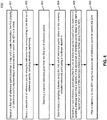
- FIG. 6 is a flow diagram illustrating a method to control an ADV according to one embodiment.
- Processing 600 may be performed by processing logic which may include software, hardware, or a combination thereof.
- processing logic may be performed by sampling module 307 of Figures 3A-3B .
- processing logic receives a first set of reference points based on a map and a route information, the first set of reference points representing a reference line in which the ADV is to follow.
- processing logic selects a second set of reference points along the reference line corresponding to the first set of reference points, including iteratively performing, at block 603, selecting a current reference point from the first set of reference points.
- processing logic plans a trajectory for the ADV using the second set of reference points to control the ADV.
- determining a sampling distance further includes determining a minimum sampling distance and determining a maximum sampling distance, where the sampling distance is determined based on the minimum sampling distance and the maximum sampling distance. In another embodiment, the sampling distance is determined further in view of a length of the reference line.
- the second set of reference points includes points that are separated by a distance approximately equal to the minimum sampling distances near the ADV and a distance approximately equal to the maximum sampling distances away from the ADV. In one embodiment, the second set of reference points has a density that gradually decreases away from the ADV.
- the nonlinear algorithm is an inverse of an exponential function.
- the nonlinear algorithm is A 1 + e Bx + C , where A is a maximum sampling distance, C is a logarithmic of A divided by a minimum sampling distance minus one, B is a logarithmic of (A/A- ⁇ )-1, minus C, divided by a length of the reference line, and ⁇ is a fractional number.
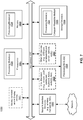
- FIG. 7 is a block diagram illustrating an example of a data processing system which may be used with one embodiment of the disclosure.
- system 1500 may represent any of data processing systems described above performing any of the processes or methods described above, such as, for example, perception and planning system 110 or servers 103-104 of Figure 1 .
- System 1500 can include many different components. These components can be implemented as integrated circuits (ICs), portions thereof, discrete electronic devices, or other modules adapted to a circuit board such as a motherboard or add-in card of the computer system, or as components otherwise incorporated within a chassis of the computer system.
- ICs integrated circuits
- System 1500 is intended to show a high level view of many components of the computer system. However, it is to be understood that additional components may be present in certain implementations and furthermore, different arrangement of the components shown may occur in other implementations.
- System 1500 may represent a desktop, a laptop, a tablet, a server, a mobile phone, a media player, a personal digital assistant (PDA), a Smartwatch, a personal communicator, a gaming device, a network router or hub, a wireless access point (AP) or repeater, a set-top box, or a combination thereof.
- PDA personal digital assistant
- AP wireless access point
- system 1500 is intended to show a high level view of many components of the computer system. However, it is to be understood that additional components may be present in certain implementations and furthermore, different arrangement of the components shown may occur in other implementations.
- System 1500 may represent a desktop, a laptop, a tablet, a server, a mobile phone, a media player, a personal digital assistant (PDA),
- system 1500 includes processor 1501, memory 1503, and devices 1505-1508 connected via a bus or an interconnect 1510.
- Processor 1501 may represent a single processor or multiple processors with a single processor core or multiple processor cores included therein.
- Processor 1501 may represent one or more general-purpose processors such as a microprocessor, a central processing unit (CPU), or the like. More particularly, processor 1501 may be a complex instruction set computing (CISC) microprocessor, reduced instruction set computing (RISC) microprocessor, very long instruction word (VLIW) microprocessor, or processor implementing other instruction sets, or processors implementing a combination of instruction sets.
- CISC complex instruction set computing
- RISC reduced instruction set computing
- VLIW very long instruction word
- Processor 1501 may also be one or more special-purpose processors such as an application specific integrated circuit (ASIC), a cellular or baseband processor, a field programmable gate array (FPGA), a digital signal processor (DSP), a network processor, a graphics processor, a communications processor, a cryptographic processor, a co-processor, an embedded processor, or any other type of logic capable of processing instructions.
- ASIC application specific integrated circuit
- FPGA field programmable gate array
- DSP digital signal processor
- network processor a graphics processor
- communications processor a cryptographic processor
- co-processor a co-processor
- embedded processor or any other type of logic capable of processing instructions.
- Processor 1501 which may be a low power multi-core processor socket such as an ultralow voltage processor, may act as a main processing unit and central hub for communication with the various components of the system. Such processor can be implemented as a system on chip (SoC). Processor 1501 is configured to execute instructions for performing the operations and steps discussed herein.
- System 1500 may further include a graphics interface that communicates with optional graphics subsystem 1504, which may include a display controller, a graphics processor, and/or a display device.
- Processor 1501 may communicate with memory 1503, which in one embodiment can be implemented via multiple memory devices to provide for a given amount of system memory.
- Memory 1503 may include one or more volatile storage (or memory) devices such as random access memory (RAM), dynamic RAM (DRAM), synchronous DRAM (SDRAM), static RAM (SRAM), or other types of storage devices.
- RAM random access memory
- DRAM dynamic RAM
- SDRAM synchronous DRAM
- SRAM static RAM
- Memory 1503 may store information including sequences of instructions that are executed by processor 1501, or any other device. For example, executable code and/or data of a variety of operating systems, device drivers, firmware (e.g., input output basic system or BIOS), and/or applications can be loaded in memory 1503 and executed by processor 1501.
- BIOS input output basic system
- An operating system can be any kind of operating systems, such as, for example, Robot Operating System (ROS), Windows® operating system from Microsoft®, Mac OS®/iOS® from Apple, Android® from Google®, LINUX, UNIX, or other real-time or embedded operating systems.
- ROS Robot Operating System
- Windows® operating system from Microsoft®
- Mac OS®/iOS® from Apple
- Android® from Google®
- LINUX LINUX
- UNIX or other real-time or embedded operating systems.
- System 1500 may further include IO devices such as devices 1505-1508, including network interface device(s) 1505, optional input device(s) 1506, and other optional IO device(s) 1507.
- Network interface device 1505 may include a wireless transceiver and/or a network interface card (NIC).
- the wireless transceiver may be a WiFi transceiver, an infrared transceiver, a Bluetooth transceiver, a WiMax transceiver, a wireless cellular telephony transceiver, a satellite transceiver (e.g., a global positioning system (GPS) transceiver), or other radio frequency (RF) transceivers, or a combination thereof.
- the NIC may be an Ethernet card.
- Input device(s) 1506 may include a mouse, a touch pad, a touch sensitive screen (which may be integrated with display device 1504), a pointer device such as a stylus, and/or a keyboard (e.g., physical keyboard or a virtual keyboard displayed as part of a touch sensitive screen).
- input device 1506 may include a touch screen controller coupled to a touch screen.
- the touch screen and touch screen controller can, for example, detect contact and movement or break thereof using any of a plurality of touch sensitivity technologies, including but not limited to capacitive, resistive, infrared, and surface acoustic wave technologies, as well as other proximity sensor arrays or other elements for determining one or more points of contact with the touch screen.
- IO devices 1507 may include an audio device.
- An audio device may include a speaker and/or a microphone to facilitate voice-enabled functions, such as voice recognition, voice replication, digital recording, and/or telephony functions.
- Other IO devices 1507 may further include universal serial bus (USB) port(s), parallel port(s), serial port(s), a printer, a network interface, a bus bridge (e.g., a PCI-PCI bridge), sensor(s) (e.g., a motion sensor such as an accelerometer, gyroscope, a magnetometer, a light sensor, compass, a proximity sensor, etc.), or a combination thereof.
- USB universal serial bus
- sensor(s) e.g., a motion sensor such as an accelerometer, gyroscope, a magnetometer, a light sensor, compass, a proximity sensor, etc.
- Devices 1507 may further include an imaging processing subsystem (e.g., a camera), which may include an optical sensor, such as a charged coupled device (CCD) or a complementary metal-oxide semiconductor (CMOS) optical sensor, utilized to facilitate camera functions, such as recording photographs and video clips.
- an imaging processing subsystem e.g., a camera
- an optical sensor such as a charged coupled device (CCD) or a complementary metal-oxide semiconductor (CMOS) optical sensor, utilized to facilitate camera functions, such as recording photographs and video clips.
- CCD charged coupled device
- CMOS complementary metal-oxide semiconductor
- Certain sensors may be coupled to interconnect 1510 via a sensor hub (not shown), while other devices such as a keyboard or thermal sensor may be controlled by an embedded controller (not shown), dependent upon the specific configuration or design of system 1500.
- a mass storage may also couple to processor 1501.
- this mass storage may be implemented via a solid state device (SSD).
- the mass storage may primarily be implemented using a hard disk drive (HDD) with a smaller amount of SSD storage to act as a SSD cache to enable non-volatile storage of context state and other such information during power down events so that a fast power up can occur on re-initiation of system activities.
- a flash device may be coupled to processor 1501, e.g., via a serial peripheral interface (SPI). This flash device may provide for non-volatile storage of system software, including BIOS as well as other firmware of the system.
- Storage device 1508 may include computer-accessible storage medium 1509 (also known as a machine-readable storage medium or a computer-readable medium) on which is stored one or more sets of instructions or software (e.g., module, unit, and/or logic 1528) embodying any one or more of the methodologies or functions described herein.
- Processing module/unit/logic 1528 may represent any of the components described above, such as, for example, routing/sampling module 307 of Figure 3 .
- Processing module/unit/logic 1528 may also reside, completely or at least partially, within memory 1503 and/or within processor 1501 during execution thereof by data processing system 1500, memory 1503 and processor 1501 also constituting machine-accessible storage media.
- Processing module/unit/logic 1528 may further be transmitted or received over a network via network interface device 1505.
- Computer-readable storage medium 1509 may also be used to store the some software functionalities described above persistently. While computer-readable storage medium 1509 is shown in an exemplary embodiment to be a single medium, the term “computer-readable storage medium” should be taken to include a single medium or multiple media (e.g., a centralized or distributed database, and/or associated caches and servers) that store the one or more sets of instructions. The terms “computer-readable storage medium” shall also be taken to include any medium that is capable of storing or encoding a set of instructions for execution by the machine and that cause the machine to perform any one or more of the methodologies of the present disclosure. The term “computer-readable storage medium” shall accordingly be taken to include, but not be limited to, solid-state memories, and optical and magnetic media, or any other non-transitory machine-readable medium.
- Processing module/unit/logic 1528, components and other features described herein can be implemented as discrete hardware components or integrated in the functionality of hardware components such as ASICS, FPGAs, DSPs or similar devices.
- processing module/unit/logic 1528 can be implemented as firmware or functional circuitry within hardware devices.
- processing module/unit/logic 1528 can be implemented in any combination hardware devices and software components.
- system 1500 is illustrated with various components of a data processing system, it is not intended to represent any particular architecture or manner of interconnecting the components; as such details are not germane to embodiments of the present disclosure. It will also be appreciated that network computers, handheld computers, mobile phones, servers, and/or other data processing systems which have fewer components or perhaps more components may also be used with embodiments of the disclosure.
- Embodiments of the disclosure also relate to an apparatus for performing the operations herein.
- a computer program is stored in a non-transitory computer readable medium.
- a machine-readable medium includes any mechanism for storing information in a form readable by a machine (e.g., a computer).
- a machine-readable (e.g., computer-readable) medium includes a machine (e.g., a computer) readable storage medium (e.g., read only memory (“ROM”), random access memory (“RAM”), magnetic disk storage media, optical storage media, flash memory devices).
- processing logic that comprises hardware (e.g. circuitry, dedicated logic, etc.), software (e.g., embodied on a non-transitory computer readable medium), or a combination of both.
- processing logic comprises hardware (e.g. circuitry, dedicated logic, etc.), software (e.g., embodied on a non-transitory computer readable medium), or a combination of both.
- Embodiments of the present disclosure are not described with reference to any particular programming language. It will be appreciated that a variety of programming languages may be used to implement the teachings of embodiments of the disclosure as described herein.
Landscapes
- Engineering & Computer Science (AREA)
- Physics & Mathematics (AREA)
- Radar, Positioning & Navigation (AREA)
- Remote Sensing (AREA)
- General Physics & Mathematics (AREA)
- Automation & Control Theory (AREA)
- Aviation & Aerospace Engineering (AREA)
- Transportation (AREA)
- Mechanical Engineering (AREA)
- Mathematical Physics (AREA)
- Electromagnetism (AREA)
- Human Computer Interaction (AREA)
- Optics & Photonics (AREA)
- Computer Vision & Pattern Recognition (AREA)
- Multimedia (AREA)
- Traffic Control Systems (AREA)
- Navigation (AREA)
- Instructional Devices (AREA)
- Control Of Driving Devices And Active Controlling Of Vehicle (AREA)
Claims (15)
- Procédé mis en œuvre par ordinateur pour commander un véhicule à conduite autonome, VCA, sur la base d'une trajectoire de conduite avec une distance d'échantillonnage progressive, le procédé comprenant les étapes consistant à :recevoir (601) un premier ensemble de points de référence sur la base d'une carte et d'une information d'itinéraire, le premier ensemble de points de référence représentant une ligne de référence que le VCA doit suivre ;sélectionner (602) un second ensemble de points de référence le long de la ligne de référence correspondant au premier ensemble de points de référence, comprenant une exécution itérative des étapes consistant à,sélectionner (603) un point de référence courant parmi le premier ensemble de points de référence ;déterminer (604) une distance d'échantillonnage le long du premier ensemble de points de référence sur la base du point de référence couramment sélectionné en utilisant un algorithme non linéaire ; etsélectionner (605) un point de référence suivant le long du premier ensemble de points de référence sur la base de la distance d'échantillonnage déterminée de telle sorte qu'une densité des points de référence sélectionnés plus proches du VCA est supérieure à une densité des points de référence sélectionnés plus éloignés du VCA ;planifier (606) une trajectoire pour le VCA en utilisant le second ensemble de points de référence ; etcommander le VCA sur la base de la trajectoire planifiée.
- Procédé mis en œuvre par ordinateur selon la revendication 1, dans lequel la détermination (604) d'une distance d'échantillonnage comprend en outre les étapes consistant à :déterminer une distance d'échantillonnage minimum ; etdéterminer une distance d'échantillonnage maximum, dans lequel la distance d'échantillonnage est déterminée sur la base de la distance d'échantillonnage minimum et de la distance d'échantillonnage maximum.
- Procédé mis en œuvre par ordinateur selon la revendication 2, dans lequel la distance d'échantillonnage est déterminée en outre eu égard à une longueur de la ligne de référence.
- Procédé mis en œuvre par ordinateur selon la revendication 1, dans lequel le second ensemble de points de référence comprend des points qui sont séparés par une distance approximativement égale aux distances d'échantillonnage minimums à proximité du VCA et une distance approximativement égale aux distances d'échantillonnage maximums loin du VCA.
- Procédé mis en œuvre par ordinateur selon la revendication 1, dans lequel le second ensemble de points de référence a une densité qui diminue progressivement en s'éloignant du VCA.
- Procédé mis en œuvre par ordinateur selon la revendication 1, dans lequel l'algorithme non linéaire est un inverse d'une fonction exponentielle.
- Procédé mis en œuvre par ordinateur selon la revendication 1, dans lequel l'algorithme non linéaire est

- Support non transitoire lisible par machine ayant des instructions stockées en son sein qui, lorsqu'elles sont exécutées par un processeur (1501), amènent le processeur (1501) à effectuer des opérations pour commander un véhicule à conduite autonome, VCA, les opérations comprenant les étapes consistant à :recevoir (601) un premier ensemble de points de référence sur la base d'une carte et d'une information d'itinéraire, le premier ensemble de points de référence représentant une ligne de référence que le VCA doit suivre ;sélectionner (602) un second ensemble de points de référence le long de la ligne de référence correspondant au premier ensemble de points de référence, comprenant une exécution itérative des étapes consistant à,sélectionner (603) un point de référence courant parmi le premier ensemble de points de référence ;déterminer (604) une distance d'échantillonnage le long du premier ensemble de points de référence sur la base du point de référence couramment sélectionné en utilisant un algorithme non linéaire ; etsélectionner (605) un point de référence suivant le long du premier ensemble de points de référence sur la base de la distance d'échantillonnage déterminée de telle sorte qu'une densité des points de référence sélectionnés plus proches du VCA est supérieure à une densité des points de référence sélectionnés plus éloignés du VCA ;planifier (606) une trajectoire pour le VCA en utilisant le second ensemble de points de référence ; etcommander le VCA sur la base de la trajectoire planifiée.
- Support non transitoire lisible par machine selon la revendication 8, dans lequel la détermination (604) d'une distance d'échantillonnage comprend en outre les étapes consistant à :déterminer une distance d'échantillonnage minimum ; etdéterminer une distance d'échantillonnage maximum, dans lequel la distance d'échantillonnage est déterminée sur la base de la distance d'échantillonnage minimum et de la distance d'échantillonnage maximum ;de préférence, la distance d'échantillonnage est déterminée en outre eu égard à une longueur de la ligne de référence.
- Support non transitoire lisible par machine selon la revendication 8, dans lequel le second ensemble de points de référence comprend des points qui sont séparés par une distance approximativement égale aux distances d'échantillonnage minimums à proximité du VCA et une distance approximativement égale aux distances d'échantillonnage maximums loin de du VCA ;
de préférence, le second ensemble de points de référence a une densité qui diminue progressivement en s'éloignant du VCA. - Support non transitoire lisible par machine selon la revendication 8, dans lequel l'algorithme non linéaire est un inverse d'une fonction exponentielle ;
de préférence, l'algorithme non linéaire est
- Système de traitement de données pour commander un véhicule à conduite autonome, VCA, comprenant :un ou plusieurs processeurs (1501) ; etune mémoire (1503) couplée aux un ou plusieurs processeurs (1501) pour stocker des instructions qui, lorsqu'elles sont exécutées par les un ou plusieurs processeurs (1501), amènent le processeur (1501) à effectuer des opérations, les opérations comprenant les étapes consistant àrecevoir (601) un premier ensemble de points de référence sur la base d'une carte et d'une information d'itinéraire, le premier ensemble de points de référence représentant une ligne de référence que le VCA doit suivre ;sélectionner (602) un second ensemble de points de référence le long de la ligne de référence correspondant au premier ensemble de points de référence, comprenant une exécution itérative des étapes consistant à,sélectionner (603) un point de référence courant à partir du premier ensemble de points de référence ;déterminer (604) une distance d'échantillonnage le long du premier ensemble de points de référence sur la base du point de référence couramment sélectionné en utilisant un algorithme non linéaire ; etsélectionner (605) un point de référence suivant le long du premier ensemble de points de référence sur la base de la distance d'échantillonnage déterminée de telle sorte qu'une densité des points de référence sélectionnés plus proches du VCA est supérieure à une densité des points de référence sélectionnés plus éloignés du VCA ;planifier (606) une trajectoire pour le VCA en utilisant le second ensemble de points de référence ; etcommander le VCA sur la base de la trajectoire planifiée.
- Système selon la revendication 12, dans lequel la détermination (604) d'une distance d'échantillonnage comprend en outre les étapes consistant à :déterminer une distance d'échantillonnage minimum ; etdéterminer une distance d'échantillonnage maximum, dans lequel la distance d'échantillonnage est déterminée sur la base de la distance d'échantillonnage minimum et de la distance d'échantillonnage maximum ; de préférence, la distance d'échantillonnage est déterminée en outre eu égard à une longueur de la ligne de référence.
- Système selon la revendication 12, dans lequel le second ensemble de points de référence comprend des points qui sont séparés d'une distance approximativement égale aux distances d'échantillonnage minimums près du VCA et d'une distance approximativement égale aux distances d'échantillonnage maximums loin du VCA ;
de préférence, le second ensemble de points de référence a une densité qui diminue progressivement en s'éloignant du VCA. - Système selon la revendication 12, dans lequel l'algorithme non linéaire est un inverse d'une fonction exponentielle ;
de préférence, l'algorithme non linéaire est
Applications Claiming Priority (1)
| Application Number | Priority Date | Filing Date | Title |
|---|---|---|---|
| US15/885,569 US10691129B2 (en) | 2018-01-31 | 2018-01-31 | Dynamically adjustable reference line sampling point density for autonomous vehicles |
Publications (2)
| Publication Number | Publication Date |
|---|---|
| EP3521963A1 EP3521963A1 (fr) | 2019-08-07 |
| EP3521963B1 true EP3521963B1 (fr) | 2021-07-07 |
Family
ID=65234405
Family Applications (1)
| Application Number | Title | Priority Date | Filing Date |
|---|---|---|---|
| EP19152965.0A Active EP3521963B1 (fr) | 2018-01-31 | 2019-01-22 | Densité de point d'échantillonnage de ligne de référence réglable dynamiquement pour véhicules autonomes |
Country Status (5)
| Country | Link |
|---|---|
| US (1) | US10691129B2 (fr) |
| EP (1) | EP3521963B1 (fr) |
| JP (1) | JP6667686B2 (fr) |
| KR (1) | KR102201045B1 (fr) |
| CN (1) | CN110096053B (fr) |
Families Citing this family (16)
| Publication number | Priority date | Publication date | Assignee | Title |
|---|---|---|---|---|
| JP6650545B1 (ja) | 2018-08-23 | 2020-02-19 | 三ツ星ベルト株式会社 | 摩擦伝動ベルト用心線および摩擦伝動ベルトならびにそれらの製造方法 |
| US11077878B2 (en) | 2018-11-02 | 2021-08-03 | Zoox, Inc. | Dynamic lane biasing |
| US11110918B2 (en) | 2018-11-02 | 2021-09-07 | Zoox, Inc. | Dynamic collision checking |
| US11048260B2 (en) * | 2018-11-02 | 2021-06-29 | Zoox, Inc. | Adaptive scaling in trajectory generation |
| US11208096B2 (en) | 2018-11-02 | 2021-12-28 | Zoox, Inc. | Cost scaling in trajectory generation |
| CN110377041B (zh) * | 2019-08-08 | 2022-03-29 | 腾讯科技(深圳)有限公司 | 参考线生成方法、装置、终端设备及存储介质 |
| CN110796707B (zh) * | 2019-09-10 | 2022-05-06 | 腾讯科技(深圳)有限公司 | 标定参数计算方法、装置以及存储介质 |
| US11958183B2 (en) | 2019-09-19 | 2024-04-16 | The Research Foundation For The State University Of New York | Negotiation-based human-robot collaboration via augmented reality |
| US11841708B2 (en) * | 2020-02-28 | 2023-12-12 | Zoox, Inc. | System and method for adjusting a planned trajectory of an autonomous vehicle |
| USD980247S1 (en) * | 2020-06-18 | 2023-03-07 | Zoox, Inc. | Display screen or portion thereof having an animated graphical user interface |
| CN112700668B (zh) * | 2020-12-22 | 2022-08-02 | 北京百度网讯科技有限公司 | 自动驾驶的远程控制方法、自动驾驶车辆及云端设备 |
| US20220258761A1 (en) * | 2021-02-18 | 2022-08-18 | Motional Ad Llc | Controlling an autonomous vehicle using variable time periods |
| CN113177665B (zh) * | 2021-05-21 | 2022-10-04 | 福建盛海智能科技有限公司 | 一种提高循迹路线精度的方法及终端 |
| CN113390431B (zh) * | 2021-06-17 | 2022-09-30 | 广东工业大学 | 动态生成参考线的方法、装置、计算机设备和存储介质 |
| CN115494833A (zh) * | 2021-06-18 | 2022-12-20 | 广州视源电子科技股份有限公司 | 机器人的控制方法和装置 |
| CN114379569B (zh) * | 2022-01-19 | 2023-11-07 | 浙江菜鸟供应链管理有限公司 | 一种生成驾驶参考线的方法及装置 |
Family Cites Families (15)
| Publication number | Priority date | Publication date | Assignee | Title |
|---|---|---|---|---|
| CN1218355A (zh) * | 1998-11-24 | 1999-06-02 | 杨更新 | 汽车自动驾驶系统 |
| US8810437B2 (en) * | 2011-02-02 | 2014-08-19 | Mapquest, Inc. | Systems and methods for generating electronic map displays with points-of-interest information based on reference locations |
| DE102011014081A1 (de) * | 2011-03-16 | 2012-09-20 | GM Global Technology Operations LLC (n. d. Gesetzen des Staates Delaware) | Verfahren zum Erkennen eines Abbiegemanövers |
| JP5766076B2 (ja) * | 2011-09-13 | 2015-08-19 | アルパイン株式会社 | 方向距離マーク使用地図表示装置 |
| CN103162702B (zh) * | 2013-03-05 | 2016-04-06 | 中山大学 | 稀疏采样下基于多重概率匹配的车辆行驶轨迹重构方法 |
| CN204303169U (zh) * | 2014-12-02 | 2015-04-29 | 曹永飞 | 一种基于车联网概念的智能车载交通信号灯信息仪 |
| CN104575004A (zh) * | 2014-12-24 | 2015-04-29 | 上海交通大学 | 基于智能移动终端的城市环境车辆测速方法及系统 |
| US9804603B1 (en) * | 2015-03-18 | 2017-10-31 | Ag Leader Technology | Curved path approximation in vehicle guidance systems and methods |
| KR101843773B1 (ko) * | 2015-06-30 | 2018-05-14 | 엘지전자 주식회사 | 차량 운전 보조 장치, 차량용 디스플레이 장치 및 차량 |
| JP6520597B2 (ja) * | 2015-09-16 | 2019-05-29 | 株式会社デンソー | 車両位置補正装置 |
| JP6558238B2 (ja) | 2015-12-22 | 2019-08-14 | アイシン・エィ・ダブリュ株式会社 | 自動運転支援システム、自動運転支援方法及びコンピュータプログラム |
| DE102016201667B4 (de) * | 2016-02-03 | 2019-06-19 | Volkswagen Aktiengesellschaft | Verfahren zum Bestimmen einer Solltrajektorie für einen ersten Verkehrsteilnehmer, insbesondere für ein Kraftfahrzeug, für einen Streckenabschnitt |
| CN107274744B (zh) * | 2016-04-07 | 2020-08-18 | 北京通汇定位科技有限公司 | 驾驶教学系统、方法和设备 |
| CN107462243B (zh) * | 2017-08-04 | 2019-09-20 | 浙江大学 | 一种基于高精度地图的云控自动驾驶任务生成方法 |
| US11126177B2 (en) * | 2018-01-24 | 2021-09-21 | Motional Ad Llc | Speed behavior planning for vehicles |
-
2018
- 2018-01-31 US US15/885,569 patent/US10691129B2/en active Active
-
2019
- 2019-01-09 CN CN201910020048.1A patent/CN110096053B/zh active Active
- 2019-01-22 EP EP19152965.0A patent/EP3521963B1/fr active Active
- 2019-01-31 JP JP2019015187A patent/JP6667686B2/ja active Active
- 2019-01-31 KR KR1020190012797A patent/KR102201045B1/ko active IP Right Grant
Non-Patent Citations (1)
| Title |
|---|
| None * |
Also Published As
| Publication number | Publication date |
|---|---|
| JP6667686B2 (ja) | 2020-03-18 |
| CN110096053B (zh) | 2022-04-29 |
| JP2019135145A (ja) | 2019-08-15 |
| CN110096053A (zh) | 2019-08-06 |
| US20190235505A1 (en) | 2019-08-01 |
| EP3521963A1 (fr) | 2019-08-07 |
| KR102201045B1 (ko) | 2021-01-08 |
| US10691129B2 (en) | 2020-06-23 |
| KR20190098914A (ko) | 2019-08-23 |
Similar Documents
| Publication | Publication Date | Title |
|---|---|---|
| EP3521963B1 (fr) | Densité de point d'échantillonnage de ligne de référence réglable dynamiquement pour véhicules autonomes | |
| EP3633408B1 (fr) | Système de perception par planification pour véhicules autonomes | |
| US10289110B2 (en) | Method to dynamically adjusting steering rates of autonomous vehicles | |
| US10579062B2 (en) | Scalable smooth reference path generator for autonomous driving vehicles | |
| EP3629121B1 (fr) | Système d'échantillonnage de trajet à courbure corrigée pour véhicules autonomes | |
| US10429849B2 (en) | Non-linear reference line optimization method using piecewise quintic polynomial spiral paths for operating autonomous driving vehicles | |
| US20200003564A1 (en) | Reference line smoothing method using piecewise spiral curves with weighted geometry costs | |
| US11230297B2 (en) | Pedestrian probability prediction system for autonomous vehicles | |
| US11099017B2 (en) | Determining driving paths for autonomous driving vehicles based on offset points | |
| US10983522B2 (en) | Emergency stop speed profile for autonomous vehicles | |
| US11561546B2 (en) | Tunnel-based planning system for autonomous driving vehicles | |
| US10908613B2 (en) | Optimal longitudinal trajectory generation under varied lateral acceleration constraints | |
| EP3652602B1 (fr) | Planification de demi-tour en trois man uvres basé sur un trajet en spirale pour véhicules à conduite autonome | |
| WO2020062033A1 (fr) | Planification de demi-tour en trois temps maitrisé par commande pour véhicules à conduite autonome (adv) | |
| US11414096B2 (en) | QP spline path and spiral path based reference line smoothing method for autonomous driving | |
| EP3655837B1 (fr) | Planification de demi-tour en trois temps à base d'énumération pour véhicules à conduite autonome | |
| EP3697659B1 (fr) | Procédé et système permettant la génération de lignes de référence pour des véhicules à conduite autonome |
Legal Events
| Date | Code | Title | Description |
|---|---|---|---|
| PUAI | Public reference made under article 153(3) epc to a published international application that has entered the european phase |
Free format text: ORIGINAL CODE: 0009012 |
|
| STAA | Information on the status of an ep patent application or granted ep patent |
Free format text: STATUS: REQUEST FOR EXAMINATION WAS MADE |
|
| 17P | Request for examination filed |
Effective date: 20190122 |
|
| AK | Designated contracting states |
Kind code of ref document: A1 Designated state(s): AL AT BE BG CH CY CZ DE DK EE ES FI FR GB GR HR HU IE IS IT LI LT LU LV MC MK MT NL NO PL PT RO RS SE SI SK SM TR |
|
| AX | Request for extension of the european patent |
Extension state: BA ME |
|
| STAA | Information on the status of an ep patent application or granted ep patent |
Free format text: STATUS: EXAMINATION IS IN PROGRESS |
|
| 17Q | First examination report despatched |
Effective date: 20200525 |
|
| STAA | Information on the status of an ep patent application or granted ep patent |
Free format text: STATUS: EXAMINATION IS IN PROGRESS |
|
| GRAP | Despatch of communication of intention to grant a patent |
Free format text: ORIGINAL CODE: EPIDOSNIGR1 |
|
| STAA | Information on the status of an ep patent application or granted ep patent |
Free format text: STATUS: GRANT OF PATENT IS INTENDED |
|
| INTG | Intention to grant announced |
Effective date: 20210303 |
|
| GRAS | Grant fee paid |
Free format text: ORIGINAL CODE: EPIDOSNIGR3 |
|
| GRAA | (expected) grant |
Free format text: ORIGINAL CODE: 0009210 |
|
| STAA | Information on the status of an ep patent application or granted ep patent |
Free format text: STATUS: THE PATENT HAS BEEN GRANTED |
|
| AK | Designated contracting states |
Kind code of ref document: B1 Designated state(s): AL AT BE BG CH CY CZ DE DK EE ES FI FR GB GR HR HU IE IS IT LI LT LU LV MC MK MT NL NO PL PT RO RS SE SI SK SM TR |
|
| REG | Reference to a national code |
Ref country code: GB Ref legal event code: FG4D |
|
| REG | Reference to a national code |
Ref country code: AT Ref legal event code: REF Ref document number: 1409196 Country of ref document: AT Kind code of ref document: T Effective date: 20210715 |
|
| REG | Reference to a national code |
Ref country code: DE Ref legal event code: R096 Ref document number: 602019005799 Country of ref document: DE |
|
| REG | Reference to a national code |
Ref country code: IE Ref legal event code: FG4D |
|
| REG | Reference to a national code |
Ref country code: LT Ref legal event code: MG9D |
|
| REG | Reference to a national code |
Ref country code: NL Ref legal event code: MP Effective date: 20210707 |
|
| REG | Reference to a national code |
Ref country code: AT Ref legal event code: MK05 Ref document number: 1409196 Country of ref document: AT Kind code of ref document: T Effective date: 20210707 |
|
| PG25 | Lapsed in a contracting state [announced via postgrant information from national office to epo] |
Ref country code: SE Free format text: LAPSE BECAUSE OF FAILURE TO SUBMIT A TRANSLATION OF THE DESCRIPTION OR TO PAY THE FEE WITHIN THE PRESCRIBED TIME-LIMIT Effective date: 20210707 Ref country code: RS Free format text: LAPSE BECAUSE OF FAILURE TO SUBMIT A TRANSLATION OF THE DESCRIPTION OR TO PAY THE FEE WITHIN THE PRESCRIBED TIME-LIMIT Effective date: 20210707 Ref country code: ES Free format text: LAPSE BECAUSE OF FAILURE TO SUBMIT A TRANSLATION OF THE DESCRIPTION OR TO PAY THE FEE WITHIN THE PRESCRIBED TIME-LIMIT Effective date: 20210707 Ref country code: FI Free format text: LAPSE BECAUSE OF FAILURE TO SUBMIT A TRANSLATION OF THE DESCRIPTION OR TO PAY THE FEE WITHIN THE PRESCRIBED TIME-LIMIT Effective date: 20210707 Ref country code: HR Free format text: LAPSE BECAUSE OF FAILURE TO SUBMIT A TRANSLATION OF THE DESCRIPTION OR TO PAY THE FEE WITHIN THE PRESCRIBED TIME-LIMIT Effective date: 20210707 Ref country code: NL Free format text: LAPSE BECAUSE OF FAILURE TO SUBMIT A TRANSLATION OF THE DESCRIPTION OR TO PAY THE FEE WITHIN THE PRESCRIBED TIME-LIMIT Effective date: 20210707 Ref country code: PT Free format text: LAPSE BECAUSE OF FAILURE TO SUBMIT A TRANSLATION OF THE DESCRIPTION OR TO PAY THE FEE WITHIN THE PRESCRIBED TIME-LIMIT Effective date: 20211108 Ref country code: NO Free format text: LAPSE BECAUSE OF FAILURE TO SUBMIT A TRANSLATION OF THE DESCRIPTION OR TO PAY THE FEE WITHIN THE PRESCRIBED TIME-LIMIT Effective date: 20211007 Ref country code: LT Free format text: LAPSE BECAUSE OF FAILURE TO SUBMIT A TRANSLATION OF THE DESCRIPTION OR TO PAY THE FEE WITHIN THE PRESCRIBED TIME-LIMIT Effective date: 20210707 Ref country code: BG Free format text: LAPSE BECAUSE OF FAILURE TO SUBMIT A TRANSLATION OF THE DESCRIPTION OR TO PAY THE FEE WITHIN THE PRESCRIBED TIME-LIMIT Effective date: 20211007 Ref country code: AT Free format text: LAPSE BECAUSE OF FAILURE TO SUBMIT A TRANSLATION OF THE DESCRIPTION OR TO PAY THE FEE WITHIN THE PRESCRIBED TIME-LIMIT Effective date: 20210707 |
|
| PG25 | Lapsed in a contracting state [announced via postgrant information from national office to epo] |
Ref country code: PL Free format text: LAPSE BECAUSE OF FAILURE TO SUBMIT A TRANSLATION OF THE DESCRIPTION OR TO PAY THE FEE WITHIN THE PRESCRIBED TIME-LIMIT Effective date: 20210707 Ref country code: LV Free format text: LAPSE BECAUSE OF FAILURE TO SUBMIT A TRANSLATION OF THE DESCRIPTION OR TO PAY THE FEE WITHIN THE PRESCRIBED TIME-LIMIT Effective date: 20210707 Ref country code: GR Free format text: LAPSE BECAUSE OF FAILURE TO SUBMIT A TRANSLATION OF THE DESCRIPTION OR TO PAY THE FEE WITHIN THE PRESCRIBED TIME-LIMIT Effective date: 20211008 |
|
| REG | Reference to a national code |
Ref country code: DE Ref legal event code: R097 Ref document number: 602019005799 Country of ref document: DE |
|
| PG25 | Lapsed in a contracting state [announced via postgrant information from national office to epo] |
Ref country code: DK Free format text: LAPSE BECAUSE OF FAILURE TO SUBMIT A TRANSLATION OF THE DESCRIPTION OR TO PAY THE FEE WITHIN THE PRESCRIBED TIME-LIMIT Effective date: 20210707 |
|
| PLBE | No opposition filed within time limit |
Free format text: ORIGINAL CODE: 0009261 |
|
| STAA | Information on the status of an ep patent application or granted ep patent |
Free format text: STATUS: NO OPPOSITION FILED WITHIN TIME LIMIT |
|
| PG25 | Lapsed in a contracting state [announced via postgrant information from national office to epo] |
Ref country code: SM Free format text: LAPSE BECAUSE OF FAILURE TO SUBMIT A TRANSLATION OF THE DESCRIPTION OR TO PAY THE FEE WITHIN THE PRESCRIBED TIME-LIMIT Effective date: 20210707 Ref country code: SK Free format text: LAPSE BECAUSE OF FAILURE TO SUBMIT A TRANSLATION OF THE DESCRIPTION OR TO PAY THE FEE WITHIN THE PRESCRIBED TIME-LIMIT Effective date: 20210707 Ref country code: RO Free format text: LAPSE BECAUSE OF FAILURE TO SUBMIT A TRANSLATION OF THE DESCRIPTION OR TO PAY THE FEE WITHIN THE PRESCRIBED TIME-LIMIT Effective date: 20210707 Ref country code: EE Free format text: LAPSE BECAUSE OF FAILURE TO SUBMIT A TRANSLATION OF THE DESCRIPTION OR TO PAY THE FEE WITHIN THE PRESCRIBED TIME-LIMIT Effective date: 20210707 Ref country code: CZ Free format text: LAPSE BECAUSE OF FAILURE TO SUBMIT A TRANSLATION OF THE DESCRIPTION OR TO PAY THE FEE WITHIN THE PRESCRIBED TIME-LIMIT Effective date: 20210707 Ref country code: AL Free format text: LAPSE BECAUSE OF FAILURE TO SUBMIT A TRANSLATION OF THE DESCRIPTION OR TO PAY THE FEE WITHIN THE PRESCRIBED TIME-LIMIT Effective date: 20210707 |
|
| 26N | No opposition filed |
Effective date: 20220408 |
|
| PG25 | Lapsed in a contracting state [announced via postgrant information from national office to epo] |
Ref country code: IT Free format text: LAPSE BECAUSE OF FAILURE TO SUBMIT A TRANSLATION OF THE DESCRIPTION OR TO PAY THE FEE WITHIN THE PRESCRIBED TIME-LIMIT Effective date: 20210707 |
|
| PG25 | Lapsed in a contracting state [announced via postgrant information from national office to epo] |
Ref country code: MC Free format text: LAPSE BECAUSE OF FAILURE TO SUBMIT A TRANSLATION OF THE DESCRIPTION OR TO PAY THE FEE WITHIN THE PRESCRIBED TIME-LIMIT Effective date: 20210707 |
|
| REG | Reference to a national code |
Ref country code: CH Ref legal event code: PL |
|
| REG | Reference to a national code |
Ref country code: BE Ref legal event code: MM Effective date: 20220131 |
|
| PG25 | Lapsed in a contracting state [announced via postgrant information from national office to epo] |
Ref country code: LU Free format text: LAPSE BECAUSE OF NON-PAYMENT OF DUE FEES Effective date: 20220122 |
|
| PG25 | Lapsed in a contracting state [announced via postgrant information from national office to epo] |
Ref country code: BE Free format text: LAPSE BECAUSE OF NON-PAYMENT OF DUE FEES Effective date: 20220131 |
|
| PG25 | Lapsed in a contracting state [announced via postgrant information from national office to epo] |
Ref country code: LI Free format text: LAPSE BECAUSE OF NON-PAYMENT OF DUE FEES Effective date: 20220131 Ref country code: CH Free format text: LAPSE BECAUSE OF NON-PAYMENT OF DUE FEES Effective date: 20220131 |
|
| PG25 | Lapsed in a contracting state [announced via postgrant information from national office to epo] |
Ref country code: IE Free format text: LAPSE BECAUSE OF NON-PAYMENT OF DUE FEES Effective date: 20220122 |
|
| P01 | Opt-out of the competence of the unified patent court (upc) registered |
Effective date: 20230526 |
|
| REG | Reference to a national code |
Ref country code: DE Ref legal event code: R079 Ref document number: 602019005799 Country of ref document: DE Free format text: PREVIOUS MAIN CLASS: G05D0001020000 Ipc: G05D0001430000 |
|
| PGFP | Annual fee paid to national office [announced via postgrant information from national office to epo] |
Ref country code: GB Payment date: 20231130 Year of fee payment: 6 |
|
| PGFP | Annual fee paid to national office [announced via postgrant information from national office to epo] |
Ref country code: FR Payment date: 20231212 Year of fee payment: 6 |
|
| PG25 | Lapsed in a contracting state [announced via postgrant information from national office to epo] |
Ref country code: MK Free format text: LAPSE BECAUSE OF FAILURE TO SUBMIT A TRANSLATION OF THE DESCRIPTION OR TO PAY THE FEE WITHIN THE PRESCRIBED TIME-LIMIT Effective date: 20210707 Ref country code: CY Free format text: LAPSE BECAUSE OF FAILURE TO SUBMIT A TRANSLATION OF THE DESCRIPTION OR TO PAY THE FEE WITHIN THE PRESCRIBED TIME-LIMIT Effective date: 20210707 |
|
| PGFP | Annual fee paid to national office [announced via postgrant information from national office to epo] |
Ref country code: DE Payment date: 20231205 Year of fee payment: 6 |