EP3521799B1 - Test result evaluating method and material tester - Google Patents
Test result evaluating method and material tester Download PDFInfo
- Publication number
- EP3521799B1 EP3521799B1 EP19154674.6A EP19154674A EP3521799B1 EP 3521799 B1 EP3521799 B1 EP 3521799B1 EP 19154674 A EP19154674 A EP 19154674A EP 3521799 B1 EP3521799 B1 EP 3521799B1
- Authority
- EP
- European Patent Office
- Prior art keywords
- test
- natural vibration
- data
- amplitude
- representative value
- Prior art date
- Legal status (The legal status is an assumption and is not a legal conclusion. Google has not performed a legal analysis and makes no representation as to the accuracy of the status listed.)
- Active
Links
Images


Classifications
-
- G—PHYSICS
- G01—MEASURING; TESTING
- G01N—INVESTIGATING OR ANALYSING MATERIALS BY DETERMINING THEIR CHEMICAL OR PHYSICAL PROPERTIES
- G01N3/00—Investigating strength properties of solid materials by application of mechanical stress
- G01N3/08—Investigating strength properties of solid materials by application of mechanical stress by applying steady tensile or compressive forces
-
- G—PHYSICS
- G01—MEASURING; TESTING
- G01H—MEASUREMENT OF MECHANICAL VIBRATIONS OR ULTRASONIC, SONIC OR INFRASONIC WAVES
- G01H1/00—Measuring characteristics of vibrations in solids by using direct conduction to the detector
- G01H1/12—Measuring characteristics of vibrations in solids by using direct conduction to the detector of longitudinal or not specified vibrations
- G01H1/16—Amplitude
-
- G—PHYSICS
- G01—MEASURING; TESTING
- G01H—MEASUREMENT OF MECHANICAL VIBRATIONS OR ULTRASONIC, SONIC OR INFRASONIC WAVES
- G01H1/00—Measuring characteristics of vibrations in solids by using direct conduction to the detector
- G01H1/12—Measuring characteristics of vibrations in solids by using direct conduction to the detector of longitudinal or not specified vibrations
- G01H1/14—Frequency
-
- G—PHYSICS
- G01—MEASURING; TESTING
- G01M—TESTING STATIC OR DYNAMIC BALANCE OF MACHINES OR STRUCTURES; TESTING OF STRUCTURES OR APPARATUS, NOT OTHERWISE PROVIDED FOR
- G01M1/00—Testing static or dynamic balance of machines or structures
- G01M1/14—Determining imbalance
-
- G—PHYSICS
- G01—MEASURING; TESTING
- G01N—INVESTIGATING OR ANALYSING MATERIALS BY DETERMINING THEIR CHEMICAL OR PHYSICAL PROPERTIES
- G01N29/00—Investigating or analysing materials by the use of ultrasonic, sonic or infrasonic waves; Visualisation of the interior of objects by transmitting ultrasonic or sonic waves through the object
- G01N29/04—Analysing solids
- G01N29/12—Analysing solids by measuring frequency or resonance of acoustic waves
-
- G—PHYSICS
- G01—MEASURING; TESTING
- G01N—INVESTIGATING OR ANALYSING MATERIALS BY DETERMINING THEIR CHEMICAL OR PHYSICAL PROPERTIES
- G01N3/00—Investigating strength properties of solid materials by application of mechanical stress
- G01N3/30—Investigating strength properties of solid materials by application of mechanical stress by applying a single impulsive force, e.g. by falling weight
-
- G—PHYSICS
- G01—MEASURING; TESTING
- G01N—INVESTIGATING OR ANALYSING MATERIALS BY DETERMINING THEIR CHEMICAL OR PHYSICAL PROPERTIES
- G01N3/00—Investigating strength properties of solid materials by application of mechanical stress
- G01N3/62—Manufacturing, calibrating, or repairing devices used in investigations covered by the preceding subgroups
-
- G—PHYSICS
- G01—MEASURING; TESTING
- G01N—INVESTIGATING OR ANALYSING MATERIALS BY DETERMINING THEIR CHEMICAL OR PHYSICAL PROPERTIES
- G01N2203/00—Investigating strength properties of solid materials by application of mechanical stress
- G01N2203/0001—Type of application of the stress
- G01N2203/001—Impulsive
-
- G—PHYSICS
- G01—MEASURING; TESTING
- G01N—INVESTIGATING OR ANALYSING MATERIALS BY DETERMINING THEIR CHEMICAL OR PHYSICAL PROPERTIES
- G01N2203/00—Investigating strength properties of solid materials by application of mechanical stress
- G01N2203/0014—Type of force applied
- G01N2203/0016—Tensile or compressive
- G01N2203/0017—Tensile
-
- G—PHYSICS
- G01—MEASURING; TESTING
- G01N—INVESTIGATING OR ANALYSING MATERIALS BY DETERMINING THEIR CHEMICAL OR PHYSICAL PROPERTIES
- G01N2203/00—Investigating strength properties of solid materials by application of mechanical stress
- G01N2203/0014—Type of force applied
- G01N2203/0021—Torsional
-
- G—PHYSICS
- G01—MEASURING; TESTING
- G01N—INVESTIGATING OR ANALYSING MATERIALS BY DETERMINING THEIR CHEMICAL OR PHYSICAL PROPERTIES
- G01N2203/00—Investigating strength properties of solid materials by application of mechanical stress
- G01N2203/003—Generation of the force
- G01N2203/0042—Pneumatic or hydraulic means
- G01N2203/0048—Hydraulic means
-
- G—PHYSICS
- G01—MEASURING; TESTING
- G01N—INVESTIGATING OR ANALYSING MATERIALS BY DETERMINING THEIR CHEMICAL OR PHYSICAL PROPERTIES
- G01N2203/00—Investigating strength properties of solid materials by application of mechanical stress
- G01N2203/02—Details not specific for a particular testing method
- G01N2203/025—Geometry of the test
- G01N2203/0252—Monoaxial, i.e. the forces being applied along a single axis of the specimen
-
- G—PHYSICS
- G01—MEASURING; TESTING
- G01N—INVESTIGATING OR ANALYSING MATERIALS BY DETERMINING THEIR CHEMICAL OR PHYSICAL PROPERTIES
- G01N2203/00—Investigating strength properties of solid materials by application of mechanical stress
- G01N2203/02—Details not specific for a particular testing method
- G01N2203/06—Indicating or recording means; Sensing means
- G01N2203/067—Parameter measured for estimating the property
- G01N2203/0676—Force, weight, load, energy, speed or acceleration
-
- G—PHYSICS
- G01—MEASURING; TESTING
- G01N—INVESTIGATING OR ANALYSING MATERIALS BY DETERMINING THEIR CHEMICAL OR PHYSICAL PROPERTIES
- G01N2203/00—Investigating strength properties of solid materials by application of mechanical stress
- G01N2203/02—Details not specific for a particular testing method
- G01N2203/06—Indicating or recording means; Sensing means
- G01N2203/067—Parameter measured for estimating the property
- G01N2203/0682—Spatial dimension, e.g. length, area, angle
-
- G—PHYSICS
- G01—MEASURING; TESTING
- G01N—INVESTIGATING OR ANALYSING MATERIALS BY DETERMINING THEIR CHEMICAL OR PHYSICAL PROPERTIES
- G01N2203/00—Investigating strength properties of solid materials by application of mechanical stress
- G01N2203/02—Details not specific for a particular testing method
- G01N2203/06—Indicating or recording means; Sensing means
- G01N2203/067—Parameter measured for estimating the property
- G01N2203/0688—Time or frequency
-
- G—PHYSICS
- G01—MEASURING; TESTING
- G01N—INVESTIGATING OR ANALYSING MATERIALS BY DETERMINING THEIR CHEMICAL OR PHYSICAL PROPERTIES
- G01N3/00—Investigating strength properties of solid materials by application of mechanical stress
- G01N3/02—Details
- G01N3/04—Chucks
Definitions
- the disclosure relates to a test result evaluating method for evaluating the reliability of a test result in a material test applying a test force to a test subject and a material tester.
- a material tester executing a material test includes a load mechanism that applies a test force to a test piece that is a testing subject and a force detector that is used for detecting a force applied to the test piece in the execution thereof (see Japanese Laid-Open No. 2004-333221 and Japanese Laid-Open 2004-333143 ).
- JP 2005 172589 discloses a test method of measuring a material property by applying a load to a test piece.
- a load output-time change characteristic and a strain output-time change characteristic are simultaneously acquired using a load cell and a strain gauge when a tensile force is applied to a test piece to measure a material property.
- the strain output in the strain output-time change characteristic is converted into an actual load, and the actual load-time change characteristic of the test piece is calculated.
- a shock of breaking or destruction of a test piece reaches the whole tester (a system including a jig and a force detector), and an amplitude according to a natural vibration of a defective tester main body is superimposed on a waveform of test data based on detection performed by the force detector.
- data is sampled over a short time interval that is 1/1000 to 1/10000 times that of a general tension test (for example, an interval of several hundred nanoseconds), and thus, superimposition of a natural vibration on test data may easily appear in a data waveform.
- the waveform represents a force that is actually applied to the test piece, and thus the reliability of a test result is degraded.
- the present disclosure has been realized for solving the problems described above, and an objective thereof is to provide a test result evaluating method and a material tester enabling a user to quantitatively acquire the reliability of a test result.
- the present invention provides a test result evaluating method according to claim 1 and a material tester according to claim 7. Further aspects of the invention are set out in the dependent claims.
- Fig. 1 is a diagram illustrating an overview of a material tester according to the disclosure.
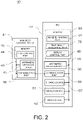
- Fig. 2 is a block diagram illustrating a main control system of the material tester according to the disclosure.
- This material tester executes a high-speed tension test of rapidly applying a shocking tensile force to a test piece TP and includes a tester main body 10 and a control device 40.
- the tester main body 10 includes a table 11, one pair of support posts 12 erected on the table 11, a cross yoke 13 stretched over the one pair of support posts 12, and a hydraulic cylinder 31 fixed to the cross yoke 13.
- the hydraulic cylinder 31 is connected to a hydraulic power source (not illustrated in the drawing) disposed inside the table 11 through a servo valve 34 and operates in accordance with a hydraulic oil supplied from the hydraulic power source.
- An upper chuck 21 is connected to a piston rod 32 of the hydraulic cylinder 31 through a run-up jig 25 and a joint 26.
- a lower chuck 22 is connected to the table 11 through a load cell 27 that is a force detector.
- the configuration of this tester main body 10 is a configuration for executing a tension test for rapidly separating one pair of chucks, which grip both end portions of the test piece TP, away from each other by disposing a run-up section in a pulling direction using the run-up jig 25 and lifting a piston rod 32 at a high speed of 0.1 to 20 m/s.
- a displacement (stroke) of a load mechanism at the time of execution of a tension test in other words, a moving amount of the piston rod 32 is detected by a stroke sensor 33, and a test force at that time is detected by the load cell 27.
- an extensometer 35 is disposed on the test piece TP.
- the extensometer 35 is directly attached to a test piece TP for measuring the expansion of the test piece TP and, for example, has a structure as disclosed in Japanese Unexamined Patent Application Publication No. 2006-10409 .
- fixing tools respectively fixed to marked lines at two positions set in the test piece TP, a pipe formed from a conductor fixed to one fixing tool, and a coil inserted into the inside of a pipe fixed to the other fixing tool to be movable are included, and a change in inductance of a coil based on a change in the amount of insertion of the coil with respect to the pipe is detected, and an expansion of the test piece TP between the marked lines is measured.
- a signal of the stroke sensor 33 may be used, or the displacement may be measured using a non-contact type extensometer such as a high-speed video camera.
- the control device 40 is composed of a main body control device 41 used for controlling the operation of the tester main body 10 and a personal computer 42.
- the main body control device 41 includes a memory 43 that stores a program, an arithmetic operation device 45 such as a micro processing unit (MPU) that executes various arithmetic operations, and a communication part 46 that communicates with the personal computer 42.
- the memory 43, the arithmetic operation device 45, and the communication part 46 are interconnected through a bus 49.
- the main body control device 41 includes a test control part 44 as a functional component.
- the test control part 44 is stored in the memory 43 as a test control program.
- a control signal is supplied to the servo valve 34, and the hydraulic cylinder 31 operates.
- Signal input/output parts respectively corresponding to the load cell 27, the stroke sensor 33, and the extensometer 35 are disposed in the main body control device 41, and an output signal of the load cell 27, an output signal of the stroke sensor 33, and an output signal of the extensometer 35 are digitalized and are taken in by the main body control device 41 at predetermined time intervals.
- the personal computer 42 includes a ROM that stores a data analysis program, a memory 53 formed by a RAM that loads a program and temporarily stores data at the time of execution of a program and the like, an arithmetic operation device 55 such as a central processing unit (CPU) executing various arithmetic operations, a communication part 56 that communicates with an externally-connected device such as the main body control device 41, a storage device 57 that stores data, a display device 51 on which a test result is displayed, and an input device 52 that is used for inputting test conditions.
- a program realizing a function by operating the arithmetic operation device 55 is stored in the memory 53.
- the storage device 57 is configured as a large-capacity storage device such as a hard disk drive (HDD) and stores time series data that is a raw data of a test force input from the load cell 27 and the like.
- the memory 53, the arithmetic operation device 55, the communication part 56, the storage device 57, the display device 51, and the input device 52 are interconnected through a bus 59.
- Fig. 2 programs that are installed in the personal computer 42 and are stored in the memory 53 are illustrated as functional blocks.
- a noise eliminating part 61 that eliminates noise components from data input from the detector
- a test result evaluating part 75 that evaluates a test result
- a display control part 69 that controls display of a test result on the display device 51 are provided as functional blocks.
- the noise eliminating part 61 includes a measurement noise eliminating part 72 that eliminates measurement noise originating from a detector such as electrical fluctuation of detectors of the load cell 27 and the extensometer 35 to be described later and a vibration noise eliminating part 74 that eliminates vibration noise assumed to be caused by an inertial force according to natural vibration of the entire tester due to the impact of breakage or destruction of the test piece TP as functional blocks.
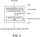
- FIG. 3 is a flowchart illustrating an overview of a test result evaluating method according to a first embodiment.
- Fig. 4 is a test force - time graph representing test data. In the graph, the vertical axis represents a test force, and the horizontal axis represents time.
- raw data which is acquired using the load cell 27, corresponding to a predetermined time period including before and after a time at which a test force is actually applied to the test piece TP is collected at a predetermined sampling rate (for example, at intervals of several hundreds of nano seconds) and is stored in the storage device 57 as time series data.
- a predetermined sampling rate for example, at intervals of several hundreds of nano seconds
- Test data used for an evaluation of a test result is that of a data period B that is data of a time period in a state in which a test force is applied to a test piece TP in data of three time periods including A: before the starting of a test at which the test force starts to be applied to a test piece, B: between a time point of starting of testing and a breaking point at which the test piece breaks in a state in which a test force is being applied to the test piece, and C: after the breaking point of the test piece illustrated in Fig. 4 .
- the test result evaluating part 75 includes a representative value calculating part 76 that sets data corresponding to a predetermined time from data of a time period representing a force applied to the test piece TP, which also includes a natural vibration, as section data and acquires a representative value in the section data and a ratio calculating part 77 that calculates a ratio between the representative value acquired by the representative value calculating part 76 and a value based on the amplitude of the natural vibration.
- the representative value calculating part 76 and the ratio calculating part 77 are disposed in the test result evaluating part 75 as programs realizing functions due to operation of the arithmetic operation device 55. Further, the arithmetic operation device 55 reads the programs from the representative value calculating part 76 and the ratio calculating part 77 and executes a representative value calculating process and a ratio calculating process, whereby the functions are realized.
- data of the data period B that is in a state in which a test force is applied to a test piece may be set as one piece of section data, or data corresponding to one period according to a natural vibration frequency in the data of the data period B, as denoted by reference sign B1 in Fig. 4 , may be set as one piece of section data.
- data of the data period B that is equally divided into four parts or the like may be set as section data.
- a representative value in section data is a value representing the section such as an average value, a moving average value, a median value, or a maximum value of the section data.
- a value representing the section such as an average value, a moving average value, a median value, or a maximum value of the section data.
- an average value of a test force in one period of the vibration or a maximum value that is a peak value may be used.
- the value based on the amplitude of a natural vibration may be a numerical value of the amplitude of the natural vibration superimposed on the test data of the data period B or a difference between a peak value and an average value in the section data.
- any other numeral value derived from the amplitude may be used.
- One period of a natural vibration used for fixing section data used for calculating a representative value using the representative value calculating part 76 is acquired as the reciprocal of the frequency of the natural vibration.
- a frequency acquired using another vibration detecting device not illustrated in the drawing by hitting the lower chuck 22 connected to the load cell 27 with a hammer or the like may be stored in the storage device 57 in advance, or a frequency acquired through a Fourier transform using the data of the data period C (see Fig. 4 ) in which a large vibration according to an impact of breakage of a test piece TP appears may be stored in the storage device 57.
- the ratio calculating part 77 calculates a ratio between the representative value of the load of the section data and the amplitude of the natural vibration (hereinafter, referred to as a load natural vibration amplitude ratio).
- the load natural vibration amplitude ratio representing a ratio of the amplitude of a natural vibration to the representative value of the load derived in this way is displayed in the display device 51 in accordance with an operation of the display control part 69 and is provided for a user as information.
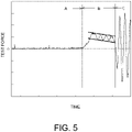
- Fig. 5 is a test force - time graph illustrating amplitude detection according to the first embodiment.
- a numerical value of the amplitude of a natural vibration that is required for the ratio calculating part 77 to acquire the load natural vibration amplitude ratio is stored in the storage device 57 in advance.
- a user may extract raw data stored in the storage device 57 of a material tester which is a result of the test, print a test force - time graph as illustrated in Fig. 5 , and acquire a straight line joining upper peak values of the waveform of the data period B and a straight line joining lower peak values on the printed graph. Thereafter, an approximate amplitude is calculated from a width between the upper and lower straight lines, and a value thereof is stored in the storage device 57.
- FIG. 6 is a flowchart illustrating a test result evaluating method according to a second embodiment.
- the same reference sign will be assigned to components similar to those of the first embodiment, and detailed description thereof will not be presented.
- This embodiment includes an amplitude detecting part 64 that calculates an amplitude of a natural vibration superimposed in the data period B (see Fig. 4 ).
- the test result evaluating part 75 includes a determination part 78 that determines reliability of a test result on the basis of the load natural vibration amplitude ratio calculated by the ratio calculating part 77.
- the amplitude detecting part 64 and the determination part 78 are arranged in the test result evaluating part 75 as a program that realizes a function by operating the arithmetic operation device 55. Then, the arithmetic operation device 55 reads programs from the amplitude detecting part 64 and the determination part 78 and executes an amplitude detecting process and a determination process, whereby the functions are realized.
- the amplitude is automatically detected from test data. Therefore, it is possible to quantitatively determine the amplitude of a natural vibration applied to the test piece TP superimposed on a test force set for a test independently of visual observation of a user.
- Fig. 7 is a flowchart illustrating amplitude detection executed by the amplitude detecting part 64.
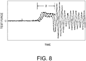
- Fig. 8 is a test force - time graph illustrating amplitude detection executed by the amplitude detecting part 64.
- the vertical axis represents a test force
- the horizontal axis represents time.
- raw data from which measurement noise has not been eliminated is denoted by a solid line.
- This amplitude detecting part 64 acquires the amplitude of a natural vibration that is superimposed on the test data of the data period B.
- Test data used for amplitude detection may be either data from which measurement noise has been eliminated by a measurement noise eliminating part 72 of the noise eliminating part 61 or raw data from which noise has not been eliminated.
- the measurement noise eliminating part 72 is configured as a noise cutting filter that eliminates a measurement noise frequency.
- the measurement noise frequency a frequency acquired by using data collected for verifying the state of the load cell 27 in advance before a test may be stored in the storage device 57, or a frequency acquired using the raw data of the data period A before a time point of test starting may be stored in the storage device 57.
- the amplitude detecting part 64 includes a period determining part 65, a maximum value/minimum value calculating part 67, and an amplitude determining part 68.
- the amplitude detection in the data period B is realized by the arithmetic operation device 55 that reads programs from the period determining part 65, the maximum value/minimum value calculating part 67, and the amplitude determining part 68 of the amplitude detecting part 64 of the memory 53 and executes a period determining process, a maximum/minimum value calculating process, and an amplitude determining process.
- the period determining part 65 acquires one period of the waveform of a natural vibration from the reciprocal of the natural vibration frequency.
- a natural vibration frequency used when one period is acquired may be acquired by another vibration detecting device in advance and stored in the storage device 57 or may be acquired by executing a Fourier transform using the data of the data period C after the breaking point.
- the maximum value/minimum value calculating part 67 calculates a maximum value and a minimum value in a time interval while moving the time interval on the data of the data period B at predetermined time intervals with reference to a time interval of one period of the waveform of the natural vibration.
- moving on the data of the data period B at predetermined time intervals represents that an operation of sliding a time interval on the data at an interval of five sampling points is repeated by assuming that there are 100 data points in the time interval of one period and an area for the calculation of a maximum value and a minimum value is moved with the time interval maintained.
- the maximum value and the minimum value acquired in this way are denoted by broken lines in Fig. 8 .
- the amplitude determining part 68 calculates a difference between the maximum value and the minimum value (the maximum value - the minimum value) denoted by the broken lines in Fig. 8 .
- a value of the difference between the maximum value and the minimum value corresponds to a wave height of the waveform of a vibration having a natural cycle that is superimposed on the test data of the data period B, and a value that is 1/2 of this value is the amplitude of the natural vibration.
- An amplitude value determined by the amplitude determining part 68 in this way is used for calculating a load natural vibration amplitude ratio using the ratio calculating part 77.
- the amplitude value is displayed in the display device 51 in accordance with an operation of the display control part 69.
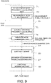
- FIG. 9 is a flowchart illustrating another method of detecting an amplitude
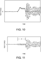
- Figs. 10 and 11 are test force - time graphs.
- the vertical axis represents a test force
- the horizontal axis represents time.
- the noise eliminating part 61 includes a measurement noise frequency calculating part 71, a measurement noise eliminating part 72, a natural vibration frequency calculating part 73, and a vibration noise eliminating part 74.
- a measurement noise frequency can be acquired for each test by the operation of the measurement noise frequency calculating part 71.
- a natural vibration frequency can be acquired for each test in accordance with an operation of the natural vibration frequency calculating part 73.
- raw data may be directly used as test data for amplitude detection without performing measurement noise elimination.
- the measurement noise frequency required for configuring a noise cutoff filter in the measurement noise eliminating part 72 a measurement noise frequency that is acquired using another method and stored in the storage device 57 in advance may be used.
- the vibration noise eliminating part 74 as the natural vibration frequency used for configuring a low pass filter for eliminating vibration noise, a frequency acquired by another vibration detecting device in advance and is stored in the storage device 57 may be used.
- vibration noise-eliminated data in which a natural vibration has been eliminated is used for amplitude detection.
- the arithmetic operation device 55 reads a program from the vibration noise eliminating part 63 of the memory 53, and vibration noise-eliminated data acquired by eliminating a natural vibration from test data is acquired.
- test data is denoted by a solid line
- vibration noise-eliminated data is denoted by a broken line.
- the amplitude detecting part 64 includes a subtraction part 66, a maximum value/minimum value calculating part 67, and the amplitude determining part 68.
- the amplitude detection in the data period B is realized by an arithmetic operation device 55 that reads programs from the subtraction part 66, the maximum value/minimum value calculating part 67, and the amplitude determining part 68 of the amplitude detecting part 64 of the memory 53 and executes a subtraction process, a maximum value/minimum value calculating process, and an amplitude determining process.
- the subtraction part 66 subtracts the vibration noise-eliminated data from the test data in the data period B. Then, the test data in the data period B, as illustrated in Fig. 11 , is converted into a waveform having an amplitude of which upper and lower widths having the test force of zero as its center are the same.
- the maximum value/minimum value calculating part 67 acquires a maximum value and a minimum value of the subtraction data of the data period B acquired by an operation of the subtraction part 66.
- maximum values and minimum values acquired by an operation of the maximum value/minimum value calculating part 67 are denoted by broken lines.
- the amplitude determining part 68 calculates a difference between the maximum value and the minimum value denoted by broken lines in Fig. 11 (the maximum value - the minimum value).
- a value of the difference between the maximum value and the minimum value corresponds to a wave height of the vibration waveform having a natural cycle that is superimposed on the test data of the data period B, and a value that is 1/2 of this value is an amplitude of the natural vibration.
- the amplitude value determined by the amplitude determining part 68 in this way is used for calculating a load natural vibration amplitude ratio using the ratio calculating part 77.
- the amplitude value is displayed on the display device 51 by an operation of the display control part 69.
- both a measurement noise frequency and a natural vibration frequency can be acquired from raw data that is acquired through an actual test. Accordingly, also even in a case in which a natural frequency of a system including a force detector and a jig of a tester main body has not been checked in advance using another vibration detecting device, amplitude detection using the natural vibration frequency can be performed, and, even in a case in which measurement noise of a detector has not been checked in advance, an appropriate noise cutoff filter can be installed using a measurement noise frequency acquired from data that has been acquired through a test.
- a representative value calculated by the representative value calculating part 76 and an amplitude value calculated by the amplitude detecting part 64 are input to the ratio calculating part 77.
- the ratio calculating part 77 receives inputs of the representative value and the amplitude value and calculates a load natural vibration amplitude ratio. Then, the load natural vibration amplitude ratio calculated by the ratio calculating part 77 is input to the determination part 78.
- the determination part 78 executes determination on the basis of one load natural vibration amplitude ratio acquired using the one representative value and an amplitude value. In the determination here, if the load natural vibration amplitude ratio exceeds a set threshold, a determination is made to evaluate the test result as defective regarding the test result evaluation, and a determination is made to evaluate the test result as good is made in a case in which the load natural vibration amplitude ratio does not exceed the threshold.
- a result of the determination output from the determination part 78 is displayed in the display device 51 by an operation of the display control part 69.
- a case in which there is one representative value calculated by the representative value calculating part 76 is a case in which a representative value is calculated by the representative value calculating part 76 using the data period B as one piece of section data or a case in which a representative value of only initial section data (represented using reference numeral B1 in Fig. 4 ) when data of the data period B corresponding to one period of the natural vibration is set as section data is calculated by the representative value calculating part 76.
- the determination part 78 executes determination on the basis of a plurality of load natural vibration amplitude ratios acquired using a representative value of each section and an amplitude value. As the determination made here, determination of two types is executed in which a determination is made to evaluate the test result as good in a case in which the load natural vibration amplitude ratio exceeds a threshold, and a determination is made to evaluate the test result as good in a case in which the load natural vibration amplitude ratio does not exceed the threshold, and comprehensive determination of whether or not there is a determination of being good with a predetermined ratio from the plurality of determination results is executed.
- a result of the comprehensive determination output from the determination part 78 is displayed in the display device 51 by an operation of the display control part 69.
- a case in which there are a plurality of representative values calculated by the representative value calculating part 76 for example, is a case in which representative values of a plurality of pieces of section data (three sections in Fig. 8 ) when data of the data period B corresponding to one period of the natural vibration is set as section data are calculated by the representative value calculating part 76 or a case in which a representative value of section data acquired by dividing the data period B into four parts is calculated by the representative value calculating part 76.
- Whether one or a plurality of pieces of section data used for calculating a representative value by the representative value calculating part 76 is set can be determined by seeing the waveform of the data period B of actual test data. Particularly, since a wave height of a waveform corresponding to the initial period of the natural vibration tends to have a high wave height, in a case in which a wave height of a subsequent waveform cycle of the natural vibration is small, a representative value may be acquired from section data corresponding to the initial period, or a maximum value may be set as the representative value with the data of the data period B regarded as section data. In addition, in a case in which a waveform having periodicity is seen from the waveform of the data period B of actual test data, a representative value of a plurality of pieces of section data may be acquired.
- test method evaluating method described above although an example in which an amplitude value of the natural vibration is acquired by a user's manual operation and an example in which an amplitude value of the natural vibration is acquired using a program installed in a personal computer have been described, the calculation of a value based on the amplitude of the natural vibration is not limited to such examples. A value based on the amplitude of the natural vibration may be supplied using other techniques.
- a load natural vibration amplitude ratio that can be quantitatively acquired is employed as an index used for evaluating a test result, and, by presenting the load natural vibration amplitude ratio to the user, an objective evaluation of a test result can be executed.
- an objective evaluation of a test result can be executed.
- displaying a result determined by the determination part 78 in the display device 51 no individual differences in the determination occur between users.
- the disclosure can be applied for checking a force according to resonance having a likelihood of participating in a test subject with being superimposed on a test force set in a test such as a high-speed compression test in which a compressive load is applied to a test body such as concrete.
Landscapes
- Physics & Mathematics (AREA)
- General Physics & Mathematics (AREA)
- Health & Medical Sciences (AREA)
- Life Sciences & Earth Sciences (AREA)
- Chemical & Material Sciences (AREA)
- Analytical Chemistry (AREA)
- Biochemistry (AREA)
- General Health & Medical Sciences (AREA)
- Immunology (AREA)
- Pathology (AREA)
- Engineering & Computer Science (AREA)
- Manufacturing & Machinery (AREA)
- Acoustics & Sound (AREA)
- Investigating Strength Of Materials By Application Of Mechanical Stress (AREA)
Applications Claiming Priority (1)
| Application Number | Priority Date | Filing Date | Title |
|---|---|---|---|
| JP2018016576A JP6911783B2 (ja) | 2018-02-01 | 2018-02-01 | 試験結果評価方法および材料試験機 |
Publications (2)
| Publication Number | Publication Date |
|---|---|
| EP3521799A1 EP3521799A1 (en) | 2019-08-07 |
| EP3521799B1 true EP3521799B1 (en) | 2022-04-20 |
Family
ID=65268890
Family Applications (1)
| Application Number | Title | Priority Date | Filing Date |
|---|---|---|---|
| EP19154674.6A Active EP3521799B1 (en) | 2018-02-01 | 2019-01-31 | Test result evaluating method and material tester |
Country Status (4)
| Country | Link |
|---|---|
| US (1) | US10690537B2 (enExample) |
| EP (1) | EP3521799B1 (enExample) |
| JP (1) | JP6911783B2 (enExample) |
| CN (1) | CN110108554B (enExample) |
Families Citing this family (7)
| Publication number | Priority date | Publication date | Assignee | Title |
|---|---|---|---|---|
| JP6866830B2 (ja) * | 2017-11-22 | 2021-04-28 | 株式会社島津製作所 | 材料試験機および把持力検出方法 |
| US11143545B2 (en) * | 2019-02-12 | 2021-10-12 | Computational Systems, Inc. | Thinning of scalar vibration data |
| JP7135932B2 (ja) * | 2019-02-26 | 2022-09-13 | 株式会社島津製作所 | 引張試験機、及び引張試験機の制御方法 |
| EP4043153A1 (en) * | 2021-02-11 | 2022-08-17 | Sandvik Mining and Construction Oy | Percussion device and method for controlling the same |
| CN114010353A (zh) * | 2021-11-05 | 2022-02-08 | 深圳市云顶信息技术有限公司 | 电动牙刷压力检测方法和电动牙刷 |
| EP4253946B1 (en) * | 2022-02-18 | 2025-10-08 | Contemporary Amperex Technology (Hong Kong) Limited | Method and device for testing electrode sheet |
| US20240219278A1 (en) * | 2022-12-23 | 2024-07-04 | Illinois Tool Works Inc. | Strut assembly for high frequency elastomer testing in a test machine used for damper testing |
Family Cites Families (20)
| Publication number | Priority date | Publication date | Assignee | Title |
|---|---|---|---|---|
| JPH0765954B2 (ja) * | 1986-10-30 | 1995-07-19 | ジャパンセンサー株式会社 | 計装化シャルピー試験機を用いた動的特性測定装置 |
| US5425276A (en) * | 1993-10-26 | 1995-06-20 | Mts Systems Corporation | Material testing system providing simultaneous force loads |
| JP2004333143A (ja) | 2003-04-30 | 2004-11-25 | Shimadzu Corp | 衝撃試験機およびその設置構造 |
| JP4062163B2 (ja) | 2003-05-02 | 2008-03-19 | 株式会社島津製作所 | 衝撃引張試験機用スパナ |
| JP4033119B2 (ja) * | 2003-12-10 | 2008-01-16 | 株式会社島津製作所 | 材料の試験方法、材料試験機 |
| JP4808936B2 (ja) * | 2004-06-03 | 2011-11-02 | 大和製衡株式会社 | 計量装置 |
| JP4164684B2 (ja) | 2004-06-23 | 2008-10-15 | 株式会社島津製作所 | 伸び計 |
| CN100480670C (zh) * | 2006-03-10 | 2009-04-22 | 浙江工业大学 | 一种基础结构测试信号的动态检测方法 |
| CN101566677A (zh) * | 2009-05-26 | 2009-10-28 | 中国电力科学研究院 | 一种故障录波器的试验结果评价方法 |
| EP2549261B1 (en) * | 2010-03-16 | 2022-06-08 | NTN Corporation | Method and device using rolling contact metallic material shear stress fatigue values in order to estimate fatigue limit surface pressure |
| CN102778394B (zh) * | 2011-05-10 | 2015-02-18 | 株式会社岛津制作所 | 材料试验机 |
| JP2013094261A (ja) * | 2011-10-28 | 2013-05-20 | Omron Healthcare Co Ltd | 測定装置、評価方法、および評価プログラム |
| US9927404B2 (en) * | 2013-03-11 | 2018-03-27 | United Technologies Corporation | Phased array billet data evaluation software |
| CN103257362B (zh) * | 2013-04-25 | 2015-07-22 | 孙赞东 | 基于压噪密度差异反演的碳酸盐岩高效井预测方法 |
| JP6460560B2 (ja) * | 2013-12-07 | 2019-01-30 | 株式会社デルタツーリング | 音・振動情報収集機構及び音・振動情報センシングシステム |
| JP6007947B2 (ja) * | 2014-06-20 | 2016-10-19 | Jfeスチール株式会社 | 自動車車体の剛性試験方法及び装置 |
| IL240316B (en) * | 2015-08-03 | 2018-10-31 | Technion Res & Dev Foundation | Method and system for parametric amplification |
| CN106353655A (zh) * | 2016-10-28 | 2017-01-25 | 西安浩能电气科技有限公司 | 电力电缆局部放电双端定位用特征脉冲发生装置及其系统和方法 |
| JP6219545B1 (ja) * | 2017-03-10 | 2017-10-25 | 住友精密工業株式会社 | 振動型角速度センサ |
| CN107121497B (zh) * | 2017-06-02 | 2019-10-08 | 东莞理工学院 | 基于Duffing系统的随机共振特性的超声导波检测方法 |
-
2018
- 2018-02-01 JP JP2018016576A patent/JP6911783B2/ja active Active
-
2019
- 2019-01-31 CN CN201910096804.9A patent/CN110108554B/zh active Active
- 2019-01-31 EP EP19154674.6A patent/EP3521799B1/en active Active
- 2019-01-31 US US16/262,952 patent/US10690537B2/en active Active
Also Published As
| Publication number | Publication date |
|---|---|
| US20190234793A1 (en) | 2019-08-01 |
| CN110108554A (zh) | 2019-08-09 |
| JP6911783B2 (ja) | 2021-07-28 |
| US10690537B2 (en) | 2020-06-23 |
| CN110108554B (zh) | 2021-09-24 |
| JP2019132766A (ja) | 2019-08-08 |
| EP3521799A1 (en) | 2019-08-07 |
Similar Documents
| Publication | Publication Date | Title |
|---|---|---|
| EP3521799B1 (en) | Test result evaluating method and material tester | |
| EP3521801B1 (en) | Test result evaluating method and a kit comprising a material tester and a hammer | |
| CN103900826B (zh) | 实时监测汽车底盘结构疲劳损伤的方法 | |
| EP3415893A1 (en) | Evaluation method of impact test and impact tester | |
| CN113358498A (zh) | 一种绳缆抗冲击性能在线实时监测装置及监测方法 | |
| CN106767475B (zh) | 一种基于横向布贴光纤光栅光谱图像分析的孔边裂纹诊断方法 | |
| DE102010023727A1 (de) | Verfahren zur schwingungsarmen optischen Kraftmessung, insbesondere auch bei hohen Temperaturen | |
| EP3415894A1 (en) | Evaluation method of impact test and impact tester | |
| JP6885276B2 (ja) | 材料試験機 | |
| KR20160055630A (ko) | 유리소재 안전성 평가 장치 및 평가 방법 | |
| EP3521802A2 (en) | Test result evaluating method and material tester | |
| Spyrakos et al. | Evaluating structural deterioration using dynamic response characterization | |
| KR101337954B1 (ko) | 금속 재료의 이축 인장 변형량 측정 장치 및 방법 | |
| JP4033119B2 (ja) | 材料の試験方法、材料試験機 | |
| EP3141305A1 (en) | Experimental method to detect the elastic modulus of objects, samples or semi-worked products of various materials | |
| CN109716100A (zh) | 材料样品、用于确定样品几何形状的方法、用于测定材料特性和/或材料特征值的方法、材料的应力应变曲线和产品 | |
| EP3875940A1 (en) | Material testing machine | |
| CN118190600B (zh) | 一种建筑混凝土的强度检测方法及系统 | |
| CN118194665B (zh) | 岩石声发射数值模拟实现方法、装置及介质 | |
| JP7396327B2 (ja) | 鋼管の加工性評価方法 | |
| JP2008197065A (ja) | 試験結果のグラフ表示装置 | |
| CN120009056A (zh) | 一种基于bim的铝合金方管变形压力检测装置及其使用方法 | |
| Golubovic-Bugarski | One approach to correlation between structural damage and dynamic response of the cantilever | |
| JP2010243322A (ja) | 材料試験機 | |
| Verleysen et al. | Advances in high strain rate material testing |
Legal Events
| Date | Code | Title | Description |
|---|---|---|---|
| PUAI | Public reference made under article 153(3) epc to a published international application that has entered the european phase |
Free format text: ORIGINAL CODE: 0009012 |
|
| STAA | Information on the status of an ep patent application or granted ep patent |
Free format text: STATUS: REQUEST FOR EXAMINATION WAS MADE |
|
| 17P | Request for examination filed |
Effective date: 20190131 |
|
| AK | Designated contracting states |
Kind code of ref document: A1 Designated state(s): AL AT BE BG CH CY CZ DE DK EE ES FI FR GB GR HR HU IE IS IT LI LT LU LV MC MK MT NL NO PL PT RO RS SE SI SK SM TR |
|
| AX | Request for extension of the european patent |
Extension state: BA ME |
|
| GRAP | Despatch of communication of intention to grant a patent |
Free format text: ORIGINAL CODE: EPIDOSNIGR1 |
|
| STAA | Information on the status of an ep patent application or granted ep patent |
Free format text: STATUS: GRANT OF PATENT IS INTENDED |
|
| RIC1 | Information provided on ipc code assigned before grant |
Ipc: G01N 3/04 20060101ALN20210830BHEP Ipc: G01N 3/30 20060101ALI20210830BHEP Ipc: G01M 7/08 20060101ALI20210830BHEP Ipc: G01N 29/04 20060101ALI20210830BHEP Ipc: G01N 3/08 20060101AFI20210830BHEP |
|
| INTG | Intention to grant announced |
Effective date: 20210924 |
|
| RIC1 | Information provided on ipc code assigned before grant |
Ipc: G01N 3/04 20060101ALN20210910BHEP Ipc: G01N 3/30 20060101ALI20210910BHEP Ipc: G01M 7/08 20060101ALI20210910BHEP Ipc: G01N 29/04 20060101ALI20210910BHEP Ipc: G01N 3/08 20060101AFI20210910BHEP |
|
| GRAJ | Information related to disapproval of communication of intention to grant by the applicant or resumption of examination proceedings by the epo deleted |
Free format text: ORIGINAL CODE: EPIDOSDIGR1 |
|
| STAA | Information on the status of an ep patent application or granted ep patent |
Free format text: STATUS: REQUEST FOR EXAMINATION WAS MADE |
|
| GRAP | Despatch of communication of intention to grant a patent |
Free format text: ORIGINAL CODE: EPIDOSNIGR1 |
|
| STAA | Information on the status of an ep patent application or granted ep patent |
Free format text: STATUS: GRANT OF PATENT IS INTENDED |
|
| INTC | Intention to grant announced (deleted) | ||
| RIC1 | Information provided on ipc code assigned before grant |
Ipc: G01N 3/04 20060101ALN20211223BHEP Ipc: G01N 3/30 20060101ALI20211223BHEP Ipc: G01M 7/08 20060101ALI20211223BHEP Ipc: G01N 29/04 20060101ALI20211223BHEP Ipc: G01N 3/08 20060101AFI20211223BHEP |
|
| INTG | Intention to grant announced |
Effective date: 20220114 |
|
| GRAS | Grant fee paid |
Free format text: ORIGINAL CODE: EPIDOSNIGR3 |
|
| GRAA | (expected) grant |
Free format text: ORIGINAL CODE: 0009210 |
|
| STAA | Information on the status of an ep patent application or granted ep patent |
Free format text: STATUS: THE PATENT HAS BEEN GRANTED |
|
| AK | Designated contracting states |
Kind code of ref document: B1 Designated state(s): AL AT BE BG CH CY CZ DE DK EE ES FI FR GB GR HR HU IE IS IT LI LT LU LV MC MK MT NL NO PL PT RO RS SE SI SK SM TR |
|
| REG | Reference to a national code |
Ref country code: GB Ref legal event code: FG4D |
|
| REG | Reference to a national code |
Ref country code: CH Ref legal event code: EP |
|
| REG | Reference to a national code |
Ref country code: DE Ref legal event code: R096 Ref document number: 602019013789 Country of ref document: DE |
|
| REG | Reference to a national code |
Ref country code: IE Ref legal event code: FG4D |
|
| REG | Reference to a national code |
Ref country code: AT Ref legal event code: REF Ref document number: 1485503 Country of ref document: AT Kind code of ref document: T Effective date: 20220515 |
|
| REG | Reference to a national code |
Ref country code: LT Ref legal event code: MG9D |
|
| REG | Reference to a national code |
Ref country code: NL Ref legal event code: MP Effective date: 20220420 |
|
| REG | Reference to a national code |
Ref country code: AT Ref legal event code: MK05 Ref document number: 1485503 Country of ref document: AT Kind code of ref document: T Effective date: 20220420 |
|
| PG25 | Lapsed in a contracting state [announced via postgrant information from national office to epo] |
Ref country code: NL Free format text: LAPSE BECAUSE OF FAILURE TO SUBMIT A TRANSLATION OF THE DESCRIPTION OR TO PAY THE FEE WITHIN THE PRESCRIBED TIME-LIMIT Effective date: 20220420 |
|
| PG25 | Lapsed in a contracting state [announced via postgrant information from national office to epo] |
Ref country code: SE Free format text: LAPSE BECAUSE OF FAILURE TO SUBMIT A TRANSLATION OF THE DESCRIPTION OR TO PAY THE FEE WITHIN THE PRESCRIBED TIME-LIMIT Effective date: 20220420 Ref country code: PT Free format text: LAPSE BECAUSE OF FAILURE TO SUBMIT A TRANSLATION OF THE DESCRIPTION OR TO PAY THE FEE WITHIN THE PRESCRIBED TIME-LIMIT Effective date: 20220822 Ref country code: NO Free format text: LAPSE BECAUSE OF FAILURE TO SUBMIT A TRANSLATION OF THE DESCRIPTION OR TO PAY THE FEE WITHIN THE PRESCRIBED TIME-LIMIT Effective date: 20220720 Ref country code: LT Free format text: LAPSE BECAUSE OF FAILURE TO SUBMIT A TRANSLATION OF THE DESCRIPTION OR TO PAY THE FEE WITHIN THE PRESCRIBED TIME-LIMIT Effective date: 20220420 Ref country code: HR Free format text: LAPSE BECAUSE OF FAILURE TO SUBMIT A TRANSLATION OF THE DESCRIPTION OR TO PAY THE FEE WITHIN THE PRESCRIBED TIME-LIMIT Effective date: 20220420 Ref country code: GR Free format text: LAPSE BECAUSE OF FAILURE TO SUBMIT A TRANSLATION OF THE DESCRIPTION OR TO PAY THE FEE WITHIN THE PRESCRIBED TIME-LIMIT Effective date: 20220721 Ref country code: FI Free format text: LAPSE BECAUSE OF FAILURE TO SUBMIT A TRANSLATION OF THE DESCRIPTION OR TO PAY THE FEE WITHIN THE PRESCRIBED TIME-LIMIT Effective date: 20220420 Ref country code: ES Free format text: LAPSE BECAUSE OF FAILURE TO SUBMIT A TRANSLATION OF THE DESCRIPTION OR TO PAY THE FEE WITHIN THE PRESCRIBED TIME-LIMIT Effective date: 20220420 Ref country code: BG Free format text: LAPSE BECAUSE OF FAILURE TO SUBMIT A TRANSLATION OF THE DESCRIPTION OR TO PAY THE FEE WITHIN THE PRESCRIBED TIME-LIMIT Effective date: 20220720 Ref country code: AT Free format text: LAPSE BECAUSE OF FAILURE TO SUBMIT A TRANSLATION OF THE DESCRIPTION OR TO PAY THE FEE WITHIN THE PRESCRIBED TIME-LIMIT Effective date: 20220420 |
|
| PG25 | Lapsed in a contracting state [announced via postgrant information from national office to epo] |
Ref country code: RS Free format text: LAPSE BECAUSE OF FAILURE TO SUBMIT A TRANSLATION OF THE DESCRIPTION OR TO PAY THE FEE WITHIN THE PRESCRIBED TIME-LIMIT Effective date: 20220420 Ref country code: PL Free format text: LAPSE BECAUSE OF FAILURE TO SUBMIT A TRANSLATION OF THE DESCRIPTION OR TO PAY THE FEE WITHIN THE PRESCRIBED TIME-LIMIT Effective date: 20220420 Ref country code: LV Free format text: LAPSE BECAUSE OF FAILURE TO SUBMIT A TRANSLATION OF THE DESCRIPTION OR TO PAY THE FEE WITHIN THE PRESCRIBED TIME-LIMIT Effective date: 20220420 Ref country code: IS Free format text: LAPSE BECAUSE OF FAILURE TO SUBMIT A TRANSLATION OF THE DESCRIPTION OR TO PAY THE FEE WITHIN THE PRESCRIBED TIME-LIMIT Effective date: 20220820 |
|
| REG | Reference to a national code |
Ref country code: DE Ref legal event code: R097 Ref document number: 602019013789 Country of ref document: DE |
|
| PG25 | Lapsed in a contracting state [announced via postgrant information from national office to epo] |
Ref country code: SM Free format text: LAPSE BECAUSE OF FAILURE TO SUBMIT A TRANSLATION OF THE DESCRIPTION OR TO PAY THE FEE WITHIN THE PRESCRIBED TIME-LIMIT Effective date: 20220420 Ref country code: SK Free format text: LAPSE BECAUSE OF FAILURE TO SUBMIT A TRANSLATION OF THE DESCRIPTION OR TO PAY THE FEE WITHIN THE PRESCRIBED TIME-LIMIT Effective date: 20220420 Ref country code: RO Free format text: LAPSE BECAUSE OF FAILURE TO SUBMIT A TRANSLATION OF THE DESCRIPTION OR TO PAY THE FEE WITHIN THE PRESCRIBED TIME-LIMIT Effective date: 20220420 Ref country code: EE Free format text: LAPSE BECAUSE OF FAILURE TO SUBMIT A TRANSLATION OF THE DESCRIPTION OR TO PAY THE FEE WITHIN THE PRESCRIBED TIME-LIMIT Effective date: 20220420 Ref country code: DK Free format text: LAPSE BECAUSE OF FAILURE TO SUBMIT A TRANSLATION OF THE DESCRIPTION OR TO PAY THE FEE WITHIN THE PRESCRIBED TIME-LIMIT Effective date: 20220420 Ref country code: CZ Free format text: LAPSE BECAUSE OF FAILURE TO SUBMIT A TRANSLATION OF THE DESCRIPTION OR TO PAY THE FEE WITHIN THE PRESCRIBED TIME-LIMIT Effective date: 20220420 |
|
| PLBE | No opposition filed within time limit |
Free format text: ORIGINAL CODE: 0009261 |
|
| STAA | Information on the status of an ep patent application or granted ep patent |
Free format text: STATUS: NO OPPOSITION FILED WITHIN TIME LIMIT |
|
| 26N | No opposition filed |
Effective date: 20230123 |
|
| PG25 | Lapsed in a contracting state [announced via postgrant information from national office to epo] |
Ref country code: AL Free format text: LAPSE BECAUSE OF FAILURE TO SUBMIT A TRANSLATION OF THE DESCRIPTION OR TO PAY THE FEE WITHIN THE PRESCRIBED TIME-LIMIT Effective date: 20220420 |
|
| PG25 | Lapsed in a contracting state [announced via postgrant information from national office to epo] |
Ref country code: SI Free format text: LAPSE BECAUSE OF FAILURE TO SUBMIT A TRANSLATION OF THE DESCRIPTION OR TO PAY THE FEE WITHIN THE PRESCRIBED TIME-LIMIT Effective date: 20220420 |
|
| REG | Reference to a national code |
Ref country code: CH Ref legal event code: PL |
|
| GBPC | Gb: european patent ceased through non-payment of renewal fee |
Effective date: 20230131 |
|
| PG25 | Lapsed in a contracting state [announced via postgrant information from national office to epo] |
Ref country code: LU Free format text: LAPSE BECAUSE OF NON-PAYMENT OF DUE FEES Effective date: 20230131 |
|
| REG | Reference to a national code |
Ref country code: BE Ref legal event code: MM Effective date: 20230131 |
|
| PG25 | Lapsed in a contracting state [announced via postgrant information from national office to epo] |
Ref country code: LI Free format text: LAPSE BECAUSE OF NON-PAYMENT OF DUE FEES Effective date: 20230131 Ref country code: GB Free format text: LAPSE BECAUSE OF NON-PAYMENT OF DUE FEES Effective date: 20230131 Ref country code: CH Free format text: LAPSE BECAUSE OF NON-PAYMENT OF DUE FEES Effective date: 20230131 |
|
| PG25 | Lapsed in a contracting state [announced via postgrant information from national office to epo] |
Ref country code: FR Free format text: LAPSE BECAUSE OF NON-PAYMENT OF DUE FEES Effective date: 20230131 Ref country code: BE Free format text: LAPSE BECAUSE OF NON-PAYMENT OF DUE FEES Effective date: 20230131 |
|
| PG25 | Lapsed in a contracting state [announced via postgrant information from national office to epo] |
Ref country code: IT Free format text: LAPSE BECAUSE OF FAILURE TO SUBMIT A TRANSLATION OF THE DESCRIPTION OR TO PAY THE FEE WITHIN THE PRESCRIBED TIME-LIMIT Effective date: 20220420 Ref country code: IE Free format text: LAPSE BECAUSE OF NON-PAYMENT OF DUE FEES Effective date: 20230131 |
|
| PGFP | Annual fee paid to national office [announced via postgrant information from national office to epo] |
Ref country code: DE Payment date: 20231205 Year of fee payment: 6 |
|
| PG25 | Lapsed in a contracting state [announced via postgrant information from national office to epo] |
Ref country code: MC Free format text: LAPSE BECAUSE OF FAILURE TO SUBMIT A TRANSLATION OF THE DESCRIPTION OR TO PAY THE FEE WITHIN THE PRESCRIBED TIME-LIMIT Effective date: 20220420 |
|
| PG25 | Lapsed in a contracting state [announced via postgrant information from national office to epo] |
Ref country code: MC Free format text: LAPSE BECAUSE OF FAILURE TO SUBMIT A TRANSLATION OF THE DESCRIPTION OR TO PAY THE FEE WITHIN THE PRESCRIBED TIME-LIMIT Effective date: 20220420 |
|
| PG25 | Lapsed in a contracting state [announced via postgrant information from national office to epo] |
Ref country code: BG Free format text: LAPSE BECAUSE OF FAILURE TO SUBMIT A TRANSLATION OF THE DESCRIPTION OR TO PAY THE FEE WITHIN THE PRESCRIBED TIME-LIMIT Effective date: 20220420 |
|
| PG25 | Lapsed in a contracting state [announced via postgrant information from national office to epo] |
Ref country code: BG Free format text: LAPSE BECAUSE OF FAILURE TO SUBMIT A TRANSLATION OF THE DESCRIPTION OR TO PAY THE FEE WITHIN THE PRESCRIBED TIME-LIMIT Effective date: 20220420 |
|
| PG25 | Lapsed in a contracting state [announced via postgrant information from national office to epo] |
Ref country code: CY Free format text: LAPSE BECAUSE OF FAILURE TO SUBMIT A TRANSLATION OF THE DESCRIPTION OR TO PAY THE FEE WITHIN THE PRESCRIBED TIME-LIMIT; INVALID AB INITIO Effective date: 20190131 |
|
| REG | Reference to a national code |
Ref country code: DE Ref legal event code: R119 Ref document number: 602019013789 Country of ref document: DE |
|
| PG25 | Lapsed in a contracting state [announced via postgrant information from national office to epo] |
Ref country code: HU Free format text: LAPSE BECAUSE OF FAILURE TO SUBMIT A TRANSLATION OF THE DESCRIPTION OR TO PAY THE FEE WITHIN THE PRESCRIBED TIME-LIMIT; INVALID AB INITIO Effective date: 20190131 |
|
| PG25 | Lapsed in a contracting state [announced via postgrant information from national office to epo] |
Ref country code: DE Free format text: LAPSE BECAUSE OF NON-PAYMENT OF DUE FEES Effective date: 20250801 |
|
| PG25 | Lapsed in a contracting state [announced via postgrant information from national office to epo] |
Ref country code: TR Free format text: LAPSE BECAUSE OF FAILURE TO SUBMIT A TRANSLATION OF THE DESCRIPTION OR TO PAY THE FEE WITHIN THE PRESCRIBED TIME-LIMIT Effective date: 20220420 |