EP3521702A1 - An ein haushaltsgerät angepasstes gassicherheitsventil - Google Patents
An ein haushaltsgerät angepasstes gassicherheitsventil Download PDFInfo
- Publication number
- EP3521702A1 EP3521702A1 EP18155227.4A EP18155227A EP3521702A1 EP 3521702 A1 EP3521702 A1 EP 3521702A1 EP 18155227 A EP18155227 A EP 18155227A EP 3521702 A1 EP3521702 A1 EP 3521702A1
- Authority
- EP
- European Patent Office
- Prior art keywords
- phase
- terminal
- safety valve
- support
- gas safety
- Prior art date
- Legal status (The legal status is an assumption and is not a legal conclusion. Google has not performed a legal analysis and makes no representation as to the accuracy of the status listed.)
- Granted
Links
- 238000004804 winding Methods 0.000 claims description 11
- 239000000853 adhesive Substances 0.000 claims description 7
- 230000001070 adhesive effect Effects 0.000 claims description 7
- 238000002347 injection Methods 0.000 claims description 3
- 239000007924 injection Substances 0.000 claims description 3
- 230000002093 peripheral effect Effects 0.000 claims description 3
- 238000004891 communication Methods 0.000 claims description 2
- 238000003466 welding Methods 0.000 description 7
- 238000007789 sealing Methods 0.000 description 5
- 239000000463 material Substances 0.000 description 2
- 229910001369 Brass Inorganic materials 0.000 description 1
- 229910052782 aluminium Inorganic materials 0.000 description 1
- XAGFODPZIPBFFR-UHFFFAOYSA-N aluminium Chemical compound [Al] XAGFODPZIPBFFR-UHFFFAOYSA-N 0.000 description 1
- 238000004873 anchoring Methods 0.000 description 1
- 239000010951 brass Substances 0.000 description 1
- 239000004020 conductor Substances 0.000 description 1
- 238000010276 construction Methods 0.000 description 1
- 239000003302 ferromagnetic material Substances 0.000 description 1
- 238000002955 isolation Methods 0.000 description 1
- 238000004519 manufacturing process Methods 0.000 description 1
- 239000002184 metal Substances 0.000 description 1
- 229910052751 metal Inorganic materials 0.000 description 1
- 239000007769 metal material Substances 0.000 description 1
- 238000000034 method Methods 0.000 description 1
- 238000000926 separation method Methods 0.000 description 1
- 239000000243 solution Substances 0.000 description 1
Images


Classifications
-
- F—MECHANICAL ENGINEERING; LIGHTING; HEATING; WEAPONS; BLASTING
- F16—ENGINEERING ELEMENTS AND UNITS; GENERAL MEASURES FOR PRODUCING AND MAINTAINING EFFECTIVE FUNCTIONING OF MACHINES OR INSTALLATIONS; THERMAL INSULATION IN GENERAL
- F16K—VALVES; TAPS; COCKS; ACTUATING-FLOATS; DEVICES FOR VENTING OR AERATING
- F16K31/00—Actuating devices; Operating means; Releasing devices
- F16K31/02—Actuating devices; Operating means; Releasing devices electric; magnetic
- F16K31/06—Actuating devices; Operating means; Releasing devices electric; magnetic using a magnet, e.g. diaphragm valves, cutting off by means of a liquid
- F16K31/0675—Electromagnet aspects, e.g. electric supply therefor
-
- H—ELECTRICITY
- H01—ELECTRIC ELEMENTS
- H01F—MAGNETS; INDUCTANCES; TRANSFORMERS; SELECTION OF MATERIALS FOR THEIR MAGNETIC PROPERTIES
- H01F5/00—Coils
- H01F5/04—Arrangements of electric connections to coils, e.g. leads
-
- F—MECHANICAL ENGINEERING; LIGHTING; HEATING; WEAPONS; BLASTING
- F16—ENGINEERING ELEMENTS AND UNITS; GENERAL MEASURES FOR PRODUCING AND MAINTAINING EFFECTIVE FUNCTIONING OF MACHINES OR INSTALLATIONS; THERMAL INSULATION IN GENERAL
- F16K—VALVES; TAPS; COCKS; ACTUATING-FLOATS; DEVICES FOR VENTING OR AERATING
- F16K17/00—Safety valves; Equalising valves, e.g. pressure relief valves
-
- F—MECHANICAL ENGINEERING; LIGHTING; HEATING; WEAPONS; BLASTING
- F16—ENGINEERING ELEMENTS AND UNITS; GENERAL MEASURES FOR PRODUCING AND MAINTAINING EFFECTIVE FUNCTIONING OF MACHINES OR INSTALLATIONS; THERMAL INSULATION IN GENERAL
- F16K—VALVES; TAPS; COCKS; ACTUATING-FLOATS; DEVICES FOR VENTING OR AERATING
- F16K31/00—Actuating devices; Operating means; Releasing devices
- F16K31/02—Actuating devices; Operating means; Releasing devices electric; magnetic
- F16K31/06—Actuating devices; Operating means; Releasing devices electric; magnetic using a magnet, e.g. diaphragm valves, cutting off by means of a liquid
- F16K31/0644—One-way valve
- F16K31/0655—Lift valves
-
- F—MECHANICAL ENGINEERING; LIGHTING; HEATING; WEAPONS; BLASTING
- F23—COMBUSTION APPARATUS; COMBUSTION PROCESSES
- F23N—REGULATING OR CONTROLLING COMBUSTION
- F23N1/00—Regulating fuel supply
- F23N1/005—Regulating fuel supply using electrical or electromechanical means
-
- F—MECHANICAL ENGINEERING; LIGHTING; HEATING; WEAPONS; BLASTING
- F23—COMBUSTION APPARATUS; COMBUSTION PROCESSES
- F23N—REGULATING OR CONTROLLING COMBUSTION
- F23N5/00—Systems for controlling combustion
- F23N5/02—Systems for controlling combustion using devices responsive to thermal changes or to thermal expansion of a medium
- F23N5/10—Systems for controlling combustion using devices responsive to thermal changes or to thermal expansion of a medium using thermocouples
- F23N5/105—Systems for controlling combustion using devices responsive to thermal changes or to thermal expansion of a medium using thermocouples using electrical or electromechanical means
-
- H—ELECTRICITY
- H01—ELECTRIC ELEMENTS
- H01F—MAGNETS; INDUCTANCES; TRANSFORMERS; SELECTION OF MATERIALS FOR THEIR MAGNETIC PROPERTIES
- H01F7/00—Magnets
- H01F7/06—Electromagnets; Actuators including electromagnets
- H01F7/08—Electromagnets; Actuators including electromagnets with armatures
- H01F7/081—Magnetic constructions
-
- H—ELECTRICITY
- H01—ELECTRIC ELEMENTS
- H01F—MAGNETS; INDUCTANCES; TRANSFORMERS; SELECTION OF MATERIALS FOR THEIR MAGNETIC PROPERTIES
- H01F7/00—Magnets
- H01F7/06—Electromagnets; Actuators including electromagnets
- H01F7/08—Electromagnets; Actuators including electromagnets with armatures
- H01F7/16—Rectilinearly-movable armatures
-
- F—MECHANICAL ENGINEERING; LIGHTING; HEATING; WEAPONS; BLASTING
- F23—COMBUSTION APPARATUS; COMBUSTION PROCESSES
- F23K—FEEDING FUEL TO COMBUSTION APPARATUS
- F23K2900/00—Special features of, or arrangements for fuel supplies
- F23K2900/05002—Valves for gaseous fuel supply lines
-
- F—MECHANICAL ENGINEERING; LIGHTING; HEATING; WEAPONS; BLASTING
- F23—COMBUSTION APPARATUS; COMBUSTION PROCESSES
- F23N—REGULATING OR CONTROLLING COMBUSTION
- F23N2235/00—Valves, nozzles or pumps
-
- F—MECHANICAL ENGINEERING; LIGHTING; HEATING; WEAPONS; BLASTING
- F23—COMBUSTION APPARATUS; COMBUSTION PROCESSES
- F23N—REGULATING OR CONTROLLING COMBUSTION
- F23N2235/00—Valves, nozzles or pumps
- F23N2235/12—Fuel valves
- F23N2235/14—Fuel valves electromagnetically operated
-
- F—MECHANICAL ENGINEERING; LIGHTING; HEATING; WEAPONS; BLASTING
- F23—COMBUSTION APPARATUS; COMBUSTION PROCESSES
- F23N—REGULATING OR CONTROLLING COMBUSTION
- F23N2235/00—Valves, nozzles or pumps
- F23N2235/12—Fuel valves
- F23N2235/24—Valve details
-
- H—ELECTRICITY
- H01—ELECTRIC ELEMENTS
- H01F—MAGNETS; INDUCTANCES; TRANSFORMERS; SELECTION OF MATERIALS FOR THEIR MAGNETIC PROPERTIES
- H01F7/00—Magnets
- H01F7/06—Electromagnets; Actuators including electromagnets
- H01F2007/062—Details of terminals or connectors for electromagnets
-
- H—ELECTRICITY
- H01—ELECTRIC ELEMENTS
- H01F—MAGNETS; INDUCTANCES; TRANSFORMERS; SELECTION OF MATERIALS FOR THEIR MAGNETIC PROPERTIES
- H01F7/00—Magnets
- H01F7/06—Electromagnets; Actuators including electromagnets
- H01F7/08—Electromagnets; Actuators including electromagnets with armatures
- H01F7/16—Rectilinearly-movable armatures
- H01F7/1638—Armatures not entering the winding
Definitions
- the present invention relates to a gas safety valve adapted to a domestic appliance.
- Gas safety valves adapted to a domestic appliance comprising an electromagnet with a fixed core, a support of the electromagnet, and a mobile armature coupled to the plug and movable with respect to the electromagnet between an open valve position in which the electromagnet is energized and the mobile armature is in contact with the electromagnet, and a closed valve position wherein the electromagnet is not energized.
- Safety valves today are limited in terms of electrical connection systems given their constructive shapes and the reduced size of their parts which have to perform many functions.
- the support or seat (which is the largest metal part that is commonly made of brass or aluminum) performs functions for supporting the assembly of the remaining parts of the safety valve, as a support for anchoring the safety valve in the gas valve of which it is a part, for the internal tightness in the safety valve to prevent gas from leaking out, as a support for the system for the electrical connection and isolation of the phase and/or ground terminals.
- safety valves By performing the function for the tightness and electrical connection in the lower area of the support of the gas safety valve, and given the reduced available space and the difficulty in welding electrical connections inside the support, safety valves perform the electrical connection on the outside by means of welding the phase wire and the ground wire of the coil to the corresponding terminal.
- Other solutions consist of performing electrical connections in the area of the core and the coil of the electromagnet of the gas safety valve, but this takes away space for the coil and it does not allow reducing the distance between terminals either.
- EP3222914A1 describes a gas safety valve adapted to a domestic appliance, comprising a electromagnet comprising a core, a reel inserted in the core, the reel comprising a projection extending axially and comprising a first electrical contact area, and a second electrical contact area, and a winding supported on the reel, the winding comprising a phase wire and a ground wire, a segment of the phase wire being arranged in the first electrical contact area, and a segment of the ground wire being arranged in the second electrical contact area, a support of the electromagnet being electrically conductive, and a phase closure, which is a phase connector, wherein the first electrical contact area is arranged inserted in the phase closure and the second electrical contact area is arranged inserted in the support, both electrical contact areas exerting an elastic force against the phase closure and the support, respectively, which assures the electrical connection between the phase wire and the phase closure, and between the ground wire and the support, respectively, the support comprising a housing in which the phase closure is arranged.
- the object of the invention is to provide a gas safety valve adapted to a domestic appliance, as defined in the claims.
- the gas safety valve of the invention describes a gas safety valve adapted to a domestic appliance, comprising an electromagnet comprising a core, a reel inserted in the core, the reel comprising a projection extending axially and comprising a first electrical contact area, and a second electrical contact area, and a winding supported on the reel, the winding comprising a phase wire and a ground wire, a segment of the phase wire being arranged in the first electrical contact area, and a segment of the ground wire being arranged in the second electrical contact area, a support of the electromagnet being electrically conductive, and a phase closure, which is a phase connector, wherein the first electrical contact area is arranged inserted in the phase closure and the second electrical contact area is arranged inserted in the support, both electrical contact areas exerting an elastic force against the phase closure and the support, respectively, which assures the electrical connection between the phase wire and the phase closure, and between the ground wire and the support, respectively, the support comprising a housing in which the phase closure is arranged.
- the gas safety valve comprises a connector comprising a base at least partially inserted in the housing of the support, said connector comprising, inserted in the base, a first end of a phase terminal and a first end of a ground terminal, the phase closure being electrically connected with the first end of the phase terminal, an inner area of the support being electrically connected with the first end of the ground terminal, and a second end of the phase terminal and a second end of the ground terminal being in contact with the outside of the gas safety valve, where the second end of the phase terminal and the second end of the ground terminal can form a standard connector.
- a gas safety valve is thereby obtained in which the electrical connections of the phase wire and the ground wire of the coil of the electromagnet with the phase closure and the support of the electromagnet of the safety valve, respectively, are performed in an inner housing of the support of the electromagnet.
- Said connectors comprise a base comprising the phase and ground terminals which is inserted in the space obtained inside the support of the electromagnet.
- FIG. 1 shows a schematic view of a known electrical connection of the prior art between a known gas safety valve 1' of the prior art and a thermocouple 50 arranged in a domestic appliance to determine the temperature in an enclosure.
- the electrical connection is performed through a chip card 60.
- the thermocouple 50 is connected to a standard connector 20e of the chip card 60 by means of a standard connector 20d.
- the output of the chip card 60 is by means of a standard connector 20e to which a cable with a standard connector 20d at one end and a standard connector 20c at the other end is connected.
- this standard connector 20c to which a cable with a standard connector 20b at one end, and a special connector 20a' at the other end is connected.
- the special connector 20a' is connected to a special output connector 20' of the gas safety valve 1'.
- FIG. 2 shows a schematic view of an electrical connection between an embodiment of the gas safety valve 1 according to the invention and a thermocouple 50 arranged in a domestic appliance to determine the temperature in an enclosure.
- the electrical connection is also performed through a chip card 60.
- the thermocouple 50 is connected to a standard connector 20e of the chip card 60 by means of a standard connector 20d.
- the output of the chip card 60 is by means of a standard connector 20e to which a cable with a standard connector 20d at one end and a standard connector 20a at the other end is connected.
- This standard connector 20a is connected to a standard output connector 20 of the gas safety valve 1 of the invention.
- the gas safety valve and the thermocouple are thereby electrically connected with exclusively standard connectors existing on the market.
- the connection is less expensive and more reliable because in addition to being performed with standard connectors out of a catalogue, and as can be seen in the embodiment shown, the number of elements used in the connection is even reduced by one cable and two connectors, one of which is a special connector.
- a gas safety valve 1 has been developed in which the internal tightness and the manner of performing the electrical connections with the phase and ground terminals is integrated inside the support of the gas safety valve 1, achieving more space to integrate different standard connector models with different electrical terminal shapes and sizes.
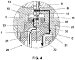
- Figure 3 shows a section view of an embodiment of an electromagnetic gas safety valve 1 according to the invention, shown in two longitudinal halves in the two valve positions, i.e., closed and open valve positions, and Figure 4 shows detail C of the gas safety valve 1 shown in Figure 3 .
- the gas safety valve 1 allows or blocks the passage of gas to a burner of the domestic appliance.
- the gas safety valve 1 comprises an electromagnet 2 supported in a support 3 or seat, a phase closure 30, a plug 4, a mobile armature 5 coupled to the plug 4 and movable between a position corresponding to the open valve (shown on the left side of Figure 3 ) and a position corresponding to the closed valve (shown on the right side of Figure 3 ), and a spring 6 suitable for returning the plug 4 together with the mobile armature 5 to the closed valve position.
- the gas safety valve 1 further comprises a case 7 enclosing therein the electromagnet 2, the mobile armature 5 and partially the support 3.
- the plug 4 is arranged coupled to the mobile armature 5 through a rod 8.
- the plug 4 is configured for being moved when it is pushed and for keeping the mobile armature 5 attracted to the electromagnet 2 when said electromagnet 2 is energized, opening the gas passage to a position in which the mobile armature 5 comes into contact with the electromagnet 2 (open valve position shown on the left side of Figure 3 ).
- the spring 6 acts on the plug 4, moving it together with the mobile armature 5 to the closed valve position (shown on the right side of Figure 3 ), closing the gas passage.
- the electromagnet 2 comprises a core 9 supported in the seat 3, a reel 10 which is arranged inserted in the core 9, and a winding 11 which arranged wound on the reel 10 and comprising a phase wire 12 and a ground wire 13.
- the core 9 has a U-shaped geometry defined by two arms attached through a base.
- the reel 10 is arranged inserted in one of the arms of the core 9.
- the core 9 and the mobile armature 5 are made of ferromagnetic materials.
- the support 3 is made of an electrically conductive material, preferably a metallic material, whereas the reel 10 is made of an electrically isolating material, preferably a plastic material.
- the reel 10 comprises a projection 17 extending axially and comprising a first electrical contact area A in which a segment of the phase wire 12 is arranged, and a second electrical contact area B in which a segment of the ground wire 13 is arranged. Both the first electrical contact area A and the second electrical contact area B are arranged inserted and compressed, respectively, against the phase closure 30 electrically connecting the phase wire 12 with the phase closure 30, and against the support 3 electrically connecting the ground wire 13 with the support 3. Both electrical contact areas A and B exert a constant elastic force against the phase closure 30 and the support 3, respectively, which assures the electrical connection between the phase wire 12 and the phase closure 30, and between the ground wire 13 and the support 3.
- the reel 10 comprises a base 14 and a hollow tubular body extending continuously and orthogonally from the base 14, and which one of the arms of the core 9 traverses.
- the projection 17 extends from the base 14, in the longitudinal direction of the gas safety valve 1, traversing the base of the core 9 and the support 3.
- the support 3, which is a substantially cylindrical part in this embodiment, is internally hollow, comprising a housing 15.
- the support 3 In its upper portion, where the electromagnet 2 is supported, the support 3 comprises a through opening communicated with the housing 15, the projection 17 of the reel 10 traversing said opening.
- a first portion of the projection 17 in which the electrical area B is located, is in electrical contact with the support 3, and a second portion of the projection 17 in which the electrical area A is located, close to the end of the projection 17, is arranged inserted in and electrical contact with in the phase closure 30, the phase closure therefore being arranged in the housing 15 of the support 3.
- the gas safety valve 1 comprises a connector 20 comprising a base 23 which is partially inserted in the housing 15 of the support 3, being inserted from the lower portion of said support 3.
- Said connector 20 comprises, inserted in the base 23, a first end of a male phase terminal 21 and a first end of a male ground terminal 22, the phase closure 30 being electrically connected with the first end of the phase terminal 21, and an inner area 31 of the support 3, which is the inner face of the support 3 in the housing 15, being electrically connected with the first end of the ground terminal 22.
- a second end of the phase terminal 21 and a second end of the ground terminal 22 are in contact with the outside of said gas safety valve 1.
- the second end of the phase terminal 21 and the second end of the ground terminal 22 can thereby form a standard connector.
- the separation of the phase terminal 21 and ground terminal 22 varies, and the inner shape of the housing 15 of the support 3 therefore varies, but the function of a connection with the external standard connector 20a is the same.
- Said function of the support 3 is to serve as a support for the phase terminal 21 and ground terminal 22, and for the base 23 of the connector 20, and on the other hand to allow for a space for the electrical connection of the phase closure 30 with the phase terminal 21, and the electrical connection of the inner area 31 of the support 3 with the ground terminal 22.
- the first end of the phase terminal 21 and the first end of the ground terminal 22 are bent at an angle, said first end of the phase terminal 21 being arranged inside the base 23 of the connector 20.
- the connector 20 comprises an opening 25 in the upper portion of the base 23, in communication with the first end of the phase terminal 21.
- One end of the phase closure 30 is introduced in the opening 25 and electrically connected with the first end of the phase terminal 21.
- the connector 20 comprises a peripheral shoulder 24 extending axially from the base 23 to the outside of the gas safety valve 1.
- the phase terminal 21 and the ground terminal 22 comprise a respective straight second end projecting from the base 23 of the connector 20 to the outside.
- the shoulder 24 of the connector 20 surrounds the phase terminal 21 and the ground terminal 22. This shoulder 24 aids in the connection with the outer standard connector 20a, which is a standard female connector in this embodiment of the gas safety valve 1.
- the phase terminal 21 and the ground terminal 22 are female, the second end of the phase terminal 21 and the second end of the ground terminal 22 being arranged inside the base 23, but in contact with the outside.
- the outer standard connector 20a in this embodiment of the gas safety valve 1 is a standard male connector.
- the gas safety valve 1 comprises a sealing gasket 40, which is annular in this embodiment.
- the phase closure 30 is cup-shaped and acts as an intermediate phase connector, differing from the phase connector of EP3222914A1 in that it has a short length and does not project from the support 3 to the outside, being arranged in the housing 15.
- said phase closure 30 is cup-shaped, with a closed end opposite the base 23 of the connector 20, and the other end being open, the projection 17 in which electrical area A is arranged being tightened introduced through said open end. This attachment enables transmitting the electrical signal.
- the closed end of the phase closure 30 is introduced in the opening 25 of the base 23 of the connector 20 and electrically connected with the first end of the phase terminal 21, such that the electrical signal can be received from the outside.
- the electrical phase signal f reaches the outer standard connector 20a from the thermocouple 50 through the chip card 60.
- the signal f is transmitted to the phase terminal 21, and it is transmitted from this phase terminal 21 to the phase closure 30 and then to electrical area A of the projection 17, and then to the winding 11 of the electromagnet 2.
- the electrical ground signal m returns from said winding 11 to the support 3 through electrical area B of the projection 17, and the signal m is transmitted from said support 3 to the ground terminal 22, and the signal m is transmitted from said ground terminal 22 to the outer standard connector 20a.
- the first end of the phase terminal 21 is welded to the phase closure 30, for example by means of a heat weld
- the first end of the ground terminal 22 of the connector 20 comprises a small semi-spherical area and is directly brought into contact under pressure against the support 3.
- the electrical connection between the first end of the phase terminal 21 and the phase closure 30 is performed by means of direct contact by means of pressure or in an elastic manner, or by means of applying an electrically conductive adhesive.
- the electrical connection between the first end of the ground terminal 22 and the inner area 31 of the support 3 is performed by means of welding, direct contact in an elastic manner, or by means of applying an electrically conductive adhesive.
- the sealing gasket 40 is arranged tightened in the housing 15 of the support 3 surrounding the phase closure 30 and against the inner area 31 of the support 3, exerting an elastic force against said inner area 31 of the support 3.
- the gas located in the gas safety valve 1 therefore cannot come out when it is open because the gasket 40 prevents it from doing so and because the phase closure 30 is closed, tightness being maintained in the support 3.
- the connector 20 is preferably made of plastic, and in the process of manufacturing the connector 20 said plastic is injection molded onto the phase terminal 21, which has previously been welded with the phase closure 30, and the ground terminal 22, forming a single part. Said part is introduced in the housing 15 of the support 3, the projection 17 being introduced in the phase closure 30.
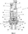
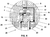
- Figure 5 shows a section view of a second embodiment of the gas safety valve 1 according to the invention, shown in two longitudinal halves in the two valve positions, i.e., closed and open valve positions, and Figure 6 shows detail D of the gas safety valve 1 shown in Figure 5 .
- This second embodiment of the gas safety valve 1 differs from the embodiment of the gas safety valve 1 previously shown in the construction of the connector 20.
- the connector 20 of this second embodiment of the gas safety valve 1 also comprises a base 23 which is partially inserted in the lower portion of the housing 15 of the support 3, being inserted from the lower portion of said support 3, and also comprises a peripheral shoulder 24 extending axially from the base 23 to the outside of the gas safety valve 1.
- Said connector 20 comprises, inserted in the base 23, a first end of a male phase terminal 21 and a first end of a male ground terminal 22, the phase closure 30 being electrically connected with the first end of the phase terminal 21, and an inner area 31 of the support 3 being electrically connected with the first end of the ground terminal 22.
- a second end of the phase terminal 21 and a second end of the ground terminal 22 are in contact with the outside of said gas safety valve 1, the shoulder 24 surrounding said second ends.
- the second end of the phase terminal 21 and the second end of the ground terminal 22 can thereby also form a standard connector.
- the support 3 also has the function of serving as a support for the phase terminal 21 and ground terminal 22, and for the base 23 of the connector 20, and on the other hand allowing for a space for the electrical connection of the phase closure 30 with the phase terminal 21, and the electrical connection of the inner area 31 of the support 3 with the ground terminal 22.
- the first end of the phase terminal 21 and the first end of the ground terminal 22 are straight and project from the base 23 of the connector 20.
- the phase terminal 21 and the ground terminal 22 are female, comprising a first end projecting from the base 23, and a second end inside the base 23, but in contact with the outside.
- the outer standard connector 20a in this embodiment of the gas safety valve 1 is a standard male connector.
- the gas safety valve 1 comprises a sealing gasket 40
- the phase closure 30 is substantially cross-shaped and acts as an intermediate phase connector, differing from the phase connector of EP3222914A1 in that it has a short length and does not project from the support 3 to the outside, being arranged in the housing 15.
- the phase closure 30 comprises a closed end opposite the base 23 of the connector 20, and the other end is open, the projection 17 in which the electrical area A is arranged being tightened introduced through said end open.
- the cross-shaped arms of the phase closure 30 allow for the support of the sealing gasket 40.
- the sealing gasket 40 is arranged surrounding the phase closure 30 and against the inner area 31 of the support 3, exerting an elastic force against said inner area 31 of the support 3.Thus, the gas that is maintained the tightness in the support 3.
- the gas safety valve 1 comprises a printed circuit board 26 comprising a printed circuit 33, as shown in the plan view of Figure 7 , and is fixed to the upper portion of the base 23 of the connector 20, the printed circuit 33 being opposite the phase closure 30.
- the first end of the phase terminal 21 and the first end of the ground terminal 22, projecting from the base 23, are inserted in the printed circuit board 26 and are in electrical contact with the printed circuit 33.
- the first end of the phase terminal 21 is electrically connected with the phase closure 30 and the first end of the ground terminal 22 is electrically connected with the inner area 31 of the support 3 through the printed circuit 33 of the printed circuit board 26.
- the printed circuit board 26 comprises an opening 32 opposite the phase closure 30, the closed end of the phase closure 30 being introduced in the opening 32.
- the attachment of the phase closure 30 with the printed circuit board 26, and therefore with the connector 20, is thereby secured and the electrical connection improved.
- the printed circuit 33 comprises an electrical phase bus 28 and an electrical ground bus 29, the first end of the phase terminal 21 being electrically connected with the electrical phase bus 28 by means of welding, and the phase closure 30 being electrically connected with the electrical bus 28 by means of welding.
- the first end of the ground terminal 22 is electrically connected with the electrical ground bus 29 by means of welding
- the inner area 31 of the support 3 is electrically connected with the electrical ground bus 29 by means of welding.
- the electrical connection between the phase closure 30 and the printed circuit board 26 is performed by means of direct contact by means of pressure or in an elastic manner, or by means of applying an electrically conductive adhesive. Furthermore, the electrical connection between the inner area 31 of the support 3 and the printed circuit board 26 is performed by means of direct contact by means of pressure or in an elastic manner, or by means of applying an electrically conductive adhesive.
- the electrical phase signal f reaches the outer standard connector 20a from the thermocouple 50 through the chip card 60.
- the signal f is transmitted to the phase terminal 21, and it is transmitted from this phase terminal 21 through the electrical phase bus 28 to the phase closure 30, and then to electrical area A of the projection 17, and finally to the winding 11 of the electromagnet 2.
- the electrical ground signal m returns from said winding 11 to the support 3 through electrical area B of the projection 17, and the signal m is transmitted from said support 3 through the electrical bus 29 of the printed circuit board 26 to the ground terminal 22, and the signal m is transmitted from said ground terminal 22 to the outer standard connector 20a.
- the connector 20 is made of injected plastic.
- the phase terminal 21 and ground terminal 22 are inserted in said connector 20, and then the formed part is assembled with the printed circuit board 26 in which the first end of the phase terminal 21 and of the ground terminal 22 are welded together.
- the plastic of the connector 20 is injection molded onto the phase terminal 21 and the ground terminal 22, forming a single part, after which the printed circuit board is assembled in said part.
Landscapes
- Engineering & Computer Science (AREA)
- General Engineering & Computer Science (AREA)
- Mechanical Engineering (AREA)
- Physics & Mathematics (AREA)
- Electromagnetism (AREA)
- Chemical & Material Sciences (AREA)
- Combustion & Propulsion (AREA)
- Power Engineering (AREA)
- Magnetically Actuated Valves (AREA)
- Feeding And Controlling Fuel (AREA)
- Electromagnets (AREA)
- Reciprocating, Oscillating Or Vibrating Motors (AREA)
- Connector Housings Or Holding Contact Members (AREA)
Priority Applications (8)
| Application Number | Priority Date | Filing Date | Title |
|---|---|---|---|
| EP18155227.4A EP3521702B1 (de) | 2018-02-06 | 2018-02-06 | An ein haushaltsgerät angepasstes gassicherheitsventil |
| KR1020190011659A KR102595390B1 (ko) | 2018-02-06 | 2019-01-30 | 가정용 기기에 적합한 가스 안전 밸브 |
| ARP190100201A AR114530A1 (es) | 2018-02-06 | 2019-01-30 | Válvula de seguridad de gas adaptada a un aparato doméstico |
| CN201910097376.1A CN110118279B (zh) | 2018-02-06 | 2019-01-31 | 适用于家用电器的气体安全阀 |
| BR102019002124A BR102019002124A2 (pt) | 2018-02-06 | 2019-02-01 | registro de segurança de gás adaptado a aparelhos domésticos |
| RU2019103202A RU2776908C2 (ru) | 2018-02-06 | 2019-02-05 | Предохранительный клапан для газа, приспособленный для бытового прибора |
| US16/267,885 US10839997B2 (en) | 2018-02-06 | 2019-02-05 | Gas safety valve |
| JP2019020093A JP7344645B2 (ja) | 2018-02-06 | 2019-02-06 | 家庭用電化製品に適合したガス安全弁 |
Applications Claiming Priority (1)
| Application Number | Priority Date | Filing Date | Title |
|---|---|---|---|
| EP18155227.4A EP3521702B1 (de) | 2018-02-06 | 2018-02-06 | An ein haushaltsgerät angepasstes gassicherheitsventil |
Publications (2)
| Publication Number | Publication Date |
|---|---|
| EP3521702A1 true EP3521702A1 (de) | 2019-08-07 |
| EP3521702B1 EP3521702B1 (de) | 2020-07-08 |
Family
ID=61692176
Family Applications (1)
| Application Number | Title | Priority Date | Filing Date |
|---|---|---|---|
| EP18155227.4A Active EP3521702B1 (de) | 2018-02-06 | 2018-02-06 | An ein haushaltsgerät angepasstes gassicherheitsventil |
Country Status (7)
| Country | Link |
|---|---|
| US (1) | US10839997B2 (de) |
| EP (1) | EP3521702B1 (de) |
| JP (1) | JP7344645B2 (de) |
| KR (1) | KR102595390B1 (de) |
| CN (1) | CN110118279B (de) |
| AR (1) | AR114530A1 (de) |
| BR (1) | BR102019002124A2 (de) |
Cited By (1)
| Publication number | Priority date | Publication date | Assignee | Title |
|---|---|---|---|---|
| WO2024189241A1 (es) | 2023-03-15 | 2024-09-19 | Orkli, S.Coop. | Válvula de seguridad de gas adaptada a un aparato doméstico |
Citations (3)
| Publication number | Priority date | Publication date | Assignee | Title |
|---|---|---|---|---|
| EP1063474A1 (de) * | 1999-06-21 | 2000-12-27 | Orkli, S. Coop. | Elektromagneteinheit für einer Sicherheitsventil |
| US20090078901A1 (en) * | 2007-09-20 | 2009-03-26 | Mondragon Componentes, S. Coop | Electromagnetic safety valve |
| EP3222914A1 (de) | 2016-03-23 | 2017-09-27 | Orkli, S. Coop. | Gassicherheitsventil |
Family Cites Families (11)
| Publication number | Priority date | Publication date | Assignee | Title |
|---|---|---|---|---|
| JPS5322126U (de) * | 1976-07-31 | 1978-02-24 | ||
| JPH0689857B2 (ja) * | 1988-03-10 | 1994-11-14 | リンナイ株式会社 | 電磁弁 |
| US5331730A (en) * | 1992-09-03 | 1994-07-26 | Siemens Automotive L.P. | Method of making a coil molded into a magnetic stator |
| JP3400187B2 (ja) * | 1995-06-05 | 2003-04-28 | パロマ工業株式会社 | 電磁弁 |
| ES2327993B1 (es) * | 2006-10-04 | 2010-09-06 | Orkli, S.Coop | Valvula electromagnetica de gas de seguridad con muelle interno. |
| ES2394611B1 (es) * | 2010-07-09 | 2013-11-28 | Orkli, S.Coop. | Acoplamiento para conectar un termopar a una válvula electromagnética adaptada a un aparato de gas. |
| DE102012101232B4 (de) * | 2012-02-16 | 2013-11-07 | Borgwarner Beru Systems Gmbh | Glühkerzensteckverbinder |
| EP2634485A1 (de) * | 2012-02-28 | 2013-09-04 | Coprececitec, S.L. | Gasventil und Methode zur Montage eines Gasventils |
| KR101886728B1 (ko) * | 2012-06-19 | 2018-08-09 | 한온시스템 주식회사 | 고전압 커넥터 조립체 |
| ES1138869Y (es) * | 2015-04-08 | 2015-07-28 | Orkli S Coop Ltda | Válvula de seguridad adaptada a un aparato de combustión a gas |
| CN104896169A (zh) * | 2015-05-11 | 2015-09-09 | 奥可利电子(昆山)有限公司 | 一种燃气熄火保护电磁阀 |
-
2018
- 2018-02-06 EP EP18155227.4A patent/EP3521702B1/de active Active
-
2019
- 2019-01-30 AR ARP190100201A patent/AR114530A1/es active IP Right Grant
- 2019-01-30 KR KR1020190011659A patent/KR102595390B1/ko active Active
- 2019-01-31 CN CN201910097376.1A patent/CN110118279B/zh active Active
- 2019-02-01 BR BR102019002124A patent/BR102019002124A2/pt not_active Application Discontinuation
- 2019-02-05 US US16/267,885 patent/US10839997B2/en active Active
- 2019-02-06 JP JP2019020093A patent/JP7344645B2/ja active Active
Patent Citations (3)
| Publication number | Priority date | Publication date | Assignee | Title |
|---|---|---|---|---|
| EP1063474A1 (de) * | 1999-06-21 | 2000-12-27 | Orkli, S. Coop. | Elektromagneteinheit für einer Sicherheitsventil |
| US20090078901A1 (en) * | 2007-09-20 | 2009-03-26 | Mondragon Componentes, S. Coop | Electromagnetic safety valve |
| EP3222914A1 (de) | 2016-03-23 | 2017-09-27 | Orkli, S. Coop. | Gassicherheitsventil |
Cited By (1)
| Publication number | Priority date | Publication date | Assignee | Title |
|---|---|---|---|---|
| WO2024189241A1 (es) | 2023-03-15 | 2024-09-19 | Orkli, S.Coop. | Válvula de seguridad de gas adaptada a un aparato doméstico |
Also Published As
| Publication number | Publication date |
|---|---|
| US10839997B2 (en) | 2020-11-17 |
| KR20190095129A (ko) | 2019-08-14 |
| EP3521702B1 (de) | 2020-07-08 |
| JP7344645B2 (ja) | 2023-09-14 |
| BR102019002124A2 (pt) | 2019-08-27 |
| CN110118279B (zh) | 2022-05-03 |
| KR102595390B1 (ko) | 2023-10-31 |
| CN110118279A (zh) | 2019-08-13 |
| US20190242490A1 (en) | 2019-08-08 |
| AR114530A1 (es) | 2020-09-16 |
| JP2019178777A (ja) | 2019-10-17 |
| RU2019103202A (ru) | 2020-08-05 |
Similar Documents
| Publication | Publication Date | Title |
|---|---|---|
| JP3592370B2 (ja) | 電磁弁 | |
| EP2766649B1 (de) | Magnetventil mit einer metallrohrspule | |
| CN110410554A (zh) | 电磁阀及其制造方法 | |
| EP3521702B1 (de) | An ein haushaltsgerät angepasstes gassicherheitsventil | |
| KR102089939B1 (ko) | 조리 기기용 안전 밸브 | |
| US5808255A (en) | Fluid pressure responsive electric switch | |
| RU2776908C2 (ru) | Предохранительный клапан для газа, приспособленный для бытового прибора | |
| JP2014020542A (ja) | 電磁弁 | |
| US6805569B2 (en) | Unit consisting of a proximity switch and a cable terminal part and a process for its manufacture | |
| KR200479375Y1 (ko) | 요리 기구에 적용된 안전 밸브 | |
| KR970000283B1 (ko) | 전기 커넥터 시스템 | |
| CN102313304B (zh) | 用于将热电偶与适用于燃气具的电磁阀连接的联接器 | |
| CN205618786U (zh) | 适用于气体燃烧器具的气体安全阀 | |
| US4429706A (en) | Safety device for gas-fired heating apparatus | |
| CN120826571A (zh) | 适用于家用电器的燃气安全阀 | |
| CN111678175B (zh) | 电磁致动器及熄火安全装置 | |
| CN218996539U (zh) | 一种开关、天线开关电路以及电子设备 | |
| US20170292623A1 (en) | Heat staked solenoid valve assembly and method | |
| JP2973240B2 (ja) | モールドコイル | |
| JP3192830U (ja) | 調理器具に適する安全弁 | |
| CN103828141B (zh) | 用在炉灶内将热电偶连接到安全电磁体和气龙头组件的设备 | |
| ES1050816U (es) | Valvula de gas de seguridad con un conector electrico | |
| JPH06181117A (ja) | 電磁石コイルのケース | |
| JP2002043124A (ja) | ソレノイド |
Legal Events
| Date | Code | Title | Description |
|---|---|---|---|
| PUAI | Public reference made under article 153(3) epc to a published international application that has entered the european phase |
Free format text: ORIGINAL CODE: 0009012 |
|
| STAA | Information on the status of an ep patent application or granted ep patent |
Free format text: STATUS: THE APPLICATION HAS BEEN PUBLISHED |
|
| AK | Designated contracting states |
Kind code of ref document: A1 Designated state(s): AL AT BE BG CH CY CZ DE DK EE ES FI FR GB GR HR HU IE IS IT LI LT LU LV MC MK MT NL NO PL PT RO RS SE SI SK SM TR |
|
| AX | Request for extension of the european patent |
Extension state: BA ME |
|
| STAA | Information on the status of an ep patent application or granted ep patent |
Free format text: STATUS: REQUEST FOR EXAMINATION WAS MADE |
|
| 17P | Request for examination filed |
Effective date: 20200207 |
|
| RBV | Designated contracting states (corrected) |
Designated state(s): AL AT BE BG CH CY CZ DE DK EE ES FI FR GB GR HR HU IE IS IT LI LT LU LV MC MK MT NL NO PL PT RO RS SE SI SK SM TR |
|
| RIC1 | Information provided on ipc code assigned before grant |
Ipc: H01F 7/16 20060101ALI20200227BHEP Ipc: H01F 7/08 20060101ALI20200227BHEP Ipc: F23N 5/10 20060101AFI20200227BHEP Ipc: F23N 1/00 20060101ALI20200227BHEP Ipc: F16K 31/06 20060101ALI20200227BHEP |
|
| GRAP | Despatch of communication of intention to grant a patent |
Free format text: ORIGINAL CODE: EPIDOSNIGR1 |
|
| STAA | Information on the status of an ep patent application or granted ep patent |
Free format text: STATUS: GRANT OF PATENT IS INTENDED |
|
| INTG | Intention to grant announced |
Effective date: 20200415 |
|
| GRAS | Grant fee paid |
Free format text: ORIGINAL CODE: EPIDOSNIGR3 |
|
| GRAA | (expected) grant |
Free format text: ORIGINAL CODE: 0009210 |
|
| STAA | Information on the status of an ep patent application or granted ep patent |
Free format text: STATUS: THE PATENT HAS BEEN GRANTED |
|
| AK | Designated contracting states |
Kind code of ref document: B1 Designated state(s): AL AT BE BG CH CY CZ DE DK EE ES FI FR GB GR HR HU IE IS IT LI LT LU LV MC MK MT NL NO PL PT RO RS SE SI SK SM TR |
|
| REG | Reference to a national code |
Ref country code: AT Ref legal event code: REF Ref document number: 1288861 Country of ref document: AT Kind code of ref document: T Effective date: 20200715 Ref country code: CH Ref legal event code: EP |
|
| REG | Reference to a national code |
Ref country code: DE Ref legal event code: R096 Ref document number: 602018005763 Country of ref document: DE |
|
| REG | Reference to a national code |
Ref country code: IE Ref legal event code: FG4D |
|
| REG | Reference to a national code |
Ref country code: LT Ref legal event code: MG4D |
|
| REG | Reference to a national code |
Ref country code: AT Ref legal event code: MK05 Ref document number: 1288861 Country of ref document: AT Kind code of ref document: T Effective date: 20200708 |
|
| REG | Reference to a national code |
Ref country code: NL Ref legal event code: MP Effective date: 20200708 |
|
| PG25 | Lapsed in a contracting state [announced via postgrant information from national office to epo] |
Ref country code: BG Free format text: LAPSE BECAUSE OF FAILURE TO SUBMIT A TRANSLATION OF THE DESCRIPTION OR TO PAY THE FEE WITHIN THE PRESCRIBED TIME-LIMIT Effective date: 20201008 Ref country code: HR Free format text: LAPSE BECAUSE OF FAILURE TO SUBMIT A TRANSLATION OF THE DESCRIPTION OR TO PAY THE FEE WITHIN THE PRESCRIBED TIME-LIMIT Effective date: 20200708 Ref country code: PT Free format text: LAPSE BECAUSE OF FAILURE TO SUBMIT A TRANSLATION OF THE DESCRIPTION OR TO PAY THE FEE WITHIN THE PRESCRIBED TIME-LIMIT Effective date: 20201109 Ref country code: FI Free format text: LAPSE BECAUSE OF FAILURE TO SUBMIT A TRANSLATION OF THE DESCRIPTION OR TO PAY THE FEE WITHIN THE PRESCRIBED TIME-LIMIT Effective date: 20200708 Ref country code: GR Free format text: LAPSE BECAUSE OF FAILURE TO SUBMIT A TRANSLATION OF THE DESCRIPTION OR TO PAY THE FEE WITHIN THE PRESCRIBED TIME-LIMIT Effective date: 20201009 Ref country code: SE Free format text: LAPSE BECAUSE OF FAILURE TO SUBMIT A TRANSLATION OF THE DESCRIPTION OR TO PAY THE FEE WITHIN THE PRESCRIBED TIME-LIMIT Effective date: 20200708 Ref country code: AT Free format text: LAPSE BECAUSE OF FAILURE TO SUBMIT A TRANSLATION OF THE DESCRIPTION OR TO PAY THE FEE WITHIN THE PRESCRIBED TIME-LIMIT Effective date: 20200708 Ref country code: NO Free format text: LAPSE BECAUSE OF FAILURE TO SUBMIT A TRANSLATION OF THE DESCRIPTION OR TO PAY THE FEE WITHIN THE PRESCRIBED TIME-LIMIT Effective date: 20201008 Ref country code: LT Free format text: LAPSE BECAUSE OF FAILURE TO SUBMIT A TRANSLATION OF THE DESCRIPTION OR TO PAY THE FEE WITHIN THE PRESCRIBED TIME-LIMIT Effective date: 20200708 Ref country code: ES Free format text: LAPSE BECAUSE OF FAILURE TO SUBMIT A TRANSLATION OF THE DESCRIPTION OR TO PAY THE FEE WITHIN THE PRESCRIBED TIME-LIMIT Effective date: 20200708 |
|
| PG25 | Lapsed in a contracting state [announced via postgrant information from national office to epo] |
Ref country code: IS Free format text: LAPSE BECAUSE OF FAILURE TO SUBMIT A TRANSLATION OF THE DESCRIPTION OR TO PAY THE FEE WITHIN THE PRESCRIBED TIME-LIMIT Effective date: 20201108 Ref country code: PL Free format text: LAPSE BECAUSE OF FAILURE TO SUBMIT A TRANSLATION OF THE DESCRIPTION OR TO PAY THE FEE WITHIN THE PRESCRIBED TIME-LIMIT Effective date: 20200708 Ref country code: LV Free format text: LAPSE BECAUSE OF FAILURE TO SUBMIT A TRANSLATION OF THE DESCRIPTION OR TO PAY THE FEE WITHIN THE PRESCRIBED TIME-LIMIT Effective date: 20200708 Ref country code: RS Free format text: LAPSE BECAUSE OF FAILURE TO SUBMIT A TRANSLATION OF THE DESCRIPTION OR TO PAY THE FEE WITHIN THE PRESCRIBED TIME-LIMIT Effective date: 20200708 |
|
| PG25 | Lapsed in a contracting state [announced via postgrant information from national office to epo] |
Ref country code: NL Free format text: LAPSE BECAUSE OF FAILURE TO SUBMIT A TRANSLATION OF THE DESCRIPTION OR TO PAY THE FEE WITHIN THE PRESCRIBED TIME-LIMIT Effective date: 20200708 |
|
| REG | Reference to a national code |
Ref country code: DE Ref legal event code: R097 Ref document number: 602018005763 Country of ref document: DE |
|
| PG25 | Lapsed in a contracting state [announced via postgrant information from national office to epo] |
Ref country code: RO Free format text: LAPSE BECAUSE OF FAILURE TO SUBMIT A TRANSLATION OF THE DESCRIPTION OR TO PAY THE FEE WITHIN THE PRESCRIBED TIME-LIMIT Effective date: 20200708 Ref country code: DK Free format text: LAPSE BECAUSE OF FAILURE TO SUBMIT A TRANSLATION OF THE DESCRIPTION OR TO PAY THE FEE WITHIN THE PRESCRIBED TIME-LIMIT Effective date: 20200708 Ref country code: CZ Free format text: LAPSE BECAUSE OF FAILURE TO SUBMIT A TRANSLATION OF THE DESCRIPTION OR TO PAY THE FEE WITHIN THE PRESCRIBED TIME-LIMIT Effective date: 20200708 Ref country code: EE Free format text: LAPSE BECAUSE OF FAILURE TO SUBMIT A TRANSLATION OF THE DESCRIPTION OR TO PAY THE FEE WITHIN THE PRESCRIBED TIME-LIMIT Effective date: 20200708 Ref country code: SM Free format text: LAPSE BECAUSE OF FAILURE TO SUBMIT A TRANSLATION OF THE DESCRIPTION OR TO PAY THE FEE WITHIN THE PRESCRIBED TIME-LIMIT Effective date: 20200708 |
|
| PLBE | No opposition filed within time limit |
Free format text: ORIGINAL CODE: 0009261 |
|
| STAA | Information on the status of an ep patent application or granted ep patent |
Free format text: STATUS: NO OPPOSITION FILED WITHIN TIME LIMIT |
|
| PG25 | Lapsed in a contracting state [announced via postgrant information from national office to epo] |
Ref country code: AL Free format text: LAPSE BECAUSE OF FAILURE TO SUBMIT A TRANSLATION OF THE DESCRIPTION OR TO PAY THE FEE WITHIN THE PRESCRIBED TIME-LIMIT Effective date: 20200708 |
|
| 26N | No opposition filed |
Effective date: 20210409 |
|
| PG25 | Lapsed in a contracting state [announced via postgrant information from national office to epo] |
Ref country code: SK Free format text: LAPSE BECAUSE OF FAILURE TO SUBMIT A TRANSLATION OF THE DESCRIPTION OR TO PAY THE FEE WITHIN THE PRESCRIBED TIME-LIMIT Effective date: 20200708 |
|
| PG25 | Lapsed in a contracting state [announced via postgrant information from national office to epo] |
Ref country code: SI Free format text: LAPSE BECAUSE OF FAILURE TO SUBMIT A TRANSLATION OF THE DESCRIPTION OR TO PAY THE FEE WITHIN THE PRESCRIBED TIME-LIMIT Effective date: 20200708 |
|
| PG25 | Lapsed in a contracting state [announced via postgrant information from national office to epo] |
Ref country code: MC Free format text: LAPSE BECAUSE OF FAILURE TO SUBMIT A TRANSLATION OF THE DESCRIPTION OR TO PAY THE FEE WITHIN THE PRESCRIBED TIME-LIMIT Effective date: 20200708 |
|
| REG | Reference to a national code |
Ref country code: BE Ref legal event code: MM Effective date: 20210228 |
|
| PG25 | Lapsed in a contracting state [announced via postgrant information from national office to epo] |
Ref country code: LI Free format text: LAPSE BECAUSE OF NON-PAYMENT OF DUE FEES Effective date: 20210228 Ref country code: LU Free format text: LAPSE BECAUSE OF NON-PAYMENT OF DUE FEES Effective date: 20210206 Ref country code: CH Free format text: LAPSE BECAUSE OF NON-PAYMENT OF DUE FEES Effective date: 20210228 |
|
| PG25 | Lapsed in a contracting state [announced via postgrant information from national office to epo] |
Ref country code: FR Free format text: LAPSE BECAUSE OF NON-PAYMENT OF DUE FEES Effective date: 20210228 Ref country code: IE Free format text: LAPSE BECAUSE OF NON-PAYMENT OF DUE FEES Effective date: 20210206 |
|
| PGFP | Annual fee paid to national office [announced via postgrant information from national office to epo] |
Ref country code: DE Payment date: 20220225 Year of fee payment: 5 |
|
| PGFP | Annual fee paid to national office [announced via postgrant information from national office to epo] |
Ref country code: TR Payment date: 20220201 Year of fee payment: 5 Ref country code: IT Payment date: 20220222 Year of fee payment: 5 |
|
| PG25 | Lapsed in a contracting state [announced via postgrant information from national office to epo] |
Ref country code: BE Free format text: LAPSE BECAUSE OF NON-PAYMENT OF DUE FEES Effective date: 20210228 |
|
| GBPC | Gb: european patent ceased through non-payment of renewal fee |
Effective date: 20220206 |
|
| PG25 | Lapsed in a contracting state [announced via postgrant information from national office to epo] |
Ref country code: GB Free format text: LAPSE BECAUSE OF NON-PAYMENT OF DUE FEES Effective date: 20220206 |
|
| PG25 | Lapsed in a contracting state [announced via postgrant information from national office to epo] |
Ref country code: CY Free format text: LAPSE BECAUSE OF FAILURE TO SUBMIT A TRANSLATION OF THE DESCRIPTION OR TO PAY THE FEE WITHIN THE PRESCRIBED TIME-LIMIT Effective date: 20200708 |
|
| PG25 | Lapsed in a contracting state [announced via postgrant information from national office to epo] |
Ref country code: HU Free format text: LAPSE BECAUSE OF FAILURE TO SUBMIT A TRANSLATION OF THE DESCRIPTION OR TO PAY THE FEE WITHIN THE PRESCRIBED TIME-LIMIT; INVALID AB INITIO Effective date: 20180206 |
|
| REG | Reference to a national code |
Ref country code: DE Ref legal event code: R119 Ref document number: 602018005763 Country of ref document: DE |
|
| PG25 | Lapsed in a contracting state [announced via postgrant information from national office to epo] |
Ref country code: IT Free format text: LAPSE BECAUSE OF NON-PAYMENT OF DUE FEES Effective date: 20230206 Ref country code: DE Free format text: LAPSE BECAUSE OF NON-PAYMENT OF DUE FEES Effective date: 20230901 |
|
| PG25 | Lapsed in a contracting state [announced via postgrant information from national office to epo] |
Ref country code: MK Free format text: LAPSE BECAUSE OF FAILURE TO SUBMIT A TRANSLATION OF THE DESCRIPTION OR TO PAY THE FEE WITHIN THE PRESCRIBED TIME-LIMIT Effective date: 20200708 |
|
| PG25 | Lapsed in a contracting state [announced via postgrant information from national office to epo] |
Ref country code: MT Free format text: LAPSE BECAUSE OF FAILURE TO SUBMIT A TRANSLATION OF THE DESCRIPTION OR TO PAY THE FEE WITHIN THE PRESCRIBED TIME-LIMIT Effective date: 20200708 |