EP3521267A1 - Procédé d'obtention de diméthyléther et de dioxyde de carbone - Google Patents
Procédé d'obtention de diméthyléther et de dioxyde de carbone Download PDFInfo
- Publication number
- EP3521267A1 EP3521267A1 EP18020582.5A EP18020582A EP3521267A1 EP 3521267 A1 EP3521267 A1 EP 3521267A1 EP 18020582 A EP18020582 A EP 18020582A EP 3521267 A1 EP3521267 A1 EP 3521267A1
- Authority
- EP
- European Patent Office
- Prior art keywords
- carbon dioxide
- separation
- hydrogen
- dimethyl ether
- carbon monoxide
- Prior art date
- Legal status (The legal status is an assumption and is not a legal conclusion. Google has not performed a legal analysis and makes no representation as to the accuracy of the status listed.)
- Granted
Links
- CURLTUGMZLYLDI-UHFFFAOYSA-N Carbon dioxide Chemical compound O=C=O CURLTUGMZLYLDI-UHFFFAOYSA-N 0.000 title claims abstract description 231
- LCGLNKUTAGEVQW-UHFFFAOYSA-N Dimethyl ether Chemical compound COC LCGLNKUTAGEVQW-UHFFFAOYSA-N 0.000 title claims abstract description 202
- 229910002092 carbon dioxide Inorganic materials 0.000 title claims abstract description 118
- 239000001569 carbon dioxide Substances 0.000 title claims abstract description 117
- 238000000034 method Methods 0.000 title claims abstract description 65
- 238000004519 manufacturing process Methods 0.000 title claims abstract description 17
- 238000000926 separation method Methods 0.000 claims abstract description 151
- OKKJLVBELUTLKV-UHFFFAOYSA-N Methanol Chemical compound OC OKKJLVBELUTLKV-UHFFFAOYSA-N 0.000 claims abstract description 141
- 230000015572 biosynthetic process Effects 0.000 claims abstract description 63
- UGFAIRIUMAVXCW-UHFFFAOYSA-N Carbon monoxide Chemical compound [O+]#[C-] UGFAIRIUMAVXCW-UHFFFAOYSA-N 0.000 claims abstract description 61
- 229910002091 carbon monoxide Inorganic materials 0.000 claims abstract description 61
- 229910052739 hydrogen Inorganic materials 0.000 claims abstract description 61
- 239000001257 hydrogen Substances 0.000 claims abstract description 61
- 239000000203 mixture Substances 0.000 claims abstract description 61
- UFHFLCQGNIYNRP-UHFFFAOYSA-N Hydrogen Chemical compound [H][H] UFHFLCQGNIYNRP-UHFFFAOYSA-N 0.000 claims abstract description 60
- 238000006243 chemical reaction Methods 0.000 claims abstract description 48
- 238000003786 synthesis reaction Methods 0.000 claims abstract description 48
- 239000007788 liquid Substances 0.000 claims abstract description 45
- XLYOFNOQVPJJNP-UHFFFAOYSA-N water Substances O XLYOFNOQVPJJNP-UHFFFAOYSA-N 0.000 claims abstract description 37
- 239000012043 crude product Substances 0.000 claims abstract description 13
- 239000007789 gas Substances 0.000 claims description 116
- 238000001816 cooling Methods 0.000 claims description 23
- 239000000047 product Substances 0.000 claims description 15
- 238000010310 metallurgical process Methods 0.000 claims description 7
- 229910052799 carbon Inorganic materials 0.000 claims description 4
- 238000009833 condensation Methods 0.000 claims description 3
- 230000005494 condensation Effects 0.000 claims description 3
- OKTJSMMVPCPJKN-UHFFFAOYSA-N Carbon Chemical compound [C] OKTJSMMVPCPJKN-UHFFFAOYSA-N 0.000 claims description 2
- 239000002032 methanolic fraction Substances 0.000 claims description 2
- 230000002950 deficient Effects 0.000 claims 1
- 238000004821 distillation Methods 0.000 claims 1
- 210000003918 fraction a Anatomy 0.000 claims 1
- 239000012530 fluid Substances 0.000 description 20
- 239000003507 refrigerant Substances 0.000 description 11
- RTZKZFJDLAIYFH-UHFFFAOYSA-N Diethyl ether Chemical compound CCOCC RTZKZFJDLAIYFH-UHFFFAOYSA-N 0.000 description 8
- ATUOYWHBWRKTHZ-UHFFFAOYSA-N Propane Chemical compound CCC ATUOYWHBWRKTHZ-UHFFFAOYSA-N 0.000 description 6
- QQONPFPTGQHPMA-UHFFFAOYSA-N Propene Chemical compound CC=C QQONPFPTGQHPMA-UHFFFAOYSA-N 0.000 description 6
- 238000009835 boiling Methods 0.000 description 6
- VNWKTOKETHGBQD-UHFFFAOYSA-N methane Chemical compound C VNWKTOKETHGBQD-UHFFFAOYSA-N 0.000 description 6
- 238000011084 recovery Methods 0.000 description 6
- 239000003054 catalyst Substances 0.000 description 5
- 239000000463 material Substances 0.000 description 5
- 239000000126 substance Substances 0.000 description 5
- 239000000498 cooling water Substances 0.000 description 4
- 238000010992 reflux Methods 0.000 description 4
- 239000004215 Carbon black (E152) Substances 0.000 description 3
- 239000006227 byproduct Substances 0.000 description 3
- 239000000571 coke Substances 0.000 description 3
- 238000005516 engineering process Methods 0.000 description 3
- 238000002309 gasification Methods 0.000 description 3
- 238000010438 heat treatment Methods 0.000 description 3
- 229930195733 hydrocarbon Natural products 0.000 description 3
- 150000002430 hydrocarbons Chemical class 0.000 description 3
- 239000001294 propane Substances 0.000 description 3
- 238000011144 upstream manufacturing Methods 0.000 description 3
- 239000002028 Biomass Substances 0.000 description 2
- 239000003245 coal Substances 0.000 description 2
- 238000002485 combustion reaction Methods 0.000 description 2
- 238000007796 conventional method Methods 0.000 description 2
- 239000000446 fuel Substances 0.000 description 2
- 230000010354 integration Effects 0.000 description 2
- 239000003345 natural gas Substances 0.000 description 2
- 238000003860 storage Methods 0.000 description 2
- CIWBSHSKHKDKBQ-JLAZNSOCSA-N Ascorbic acid Chemical compound OC[C@H](O)[C@H]1OC(=O)C(O)=C1O CIWBSHSKHKDKBQ-JLAZNSOCSA-N 0.000 description 1
- RWSOTUBLDIXVET-UHFFFAOYSA-N Dihydrogen sulfide Chemical compound S RWSOTUBLDIXVET-UHFFFAOYSA-N 0.000 description 1
- OTMSDBZUPAUEDD-UHFFFAOYSA-N Ethane Chemical compound CC OTMSDBZUPAUEDD-UHFFFAOYSA-N 0.000 description 1
- NINIDFKCEFEMDL-UHFFFAOYSA-N Sulfur Chemical compound [S] NINIDFKCEFEMDL-UHFFFAOYSA-N 0.000 description 1
- 230000032683 aging Effects 0.000 description 1
- 150000001298 alcohols Chemical class 0.000 description 1
- 230000001588 bifunctional effect Effects 0.000 description 1
- 239000002551 biofuel Substances 0.000 description 1
- 238000003889 chemical engineering Methods 0.000 description 1
- 238000001311 chemical methods and process Methods 0.000 description 1
- 239000000356 contaminant Substances 0.000 description 1
- 208000012839 conversion disease Diseases 0.000 description 1
- 239000002826 coolant Substances 0.000 description 1
- 230000018044 dehydration Effects 0.000 description 1
- 238000006297 dehydration reaction Methods 0.000 description 1
- 230000001419 dependent effect Effects 0.000 description 1
- 230000000779 depleting effect Effects 0.000 description 1
- 238000006477 desulfuration reaction Methods 0.000 description 1
- 230000023556 desulfurization Effects 0.000 description 1
- -1 desulfurization Substances 0.000 description 1
- 239000003599 detergent Substances 0.000 description 1
- 238000010586 diagram Methods 0.000 description 1
- 238000007700 distillative separation Methods 0.000 description 1
- 238000001035 drying Methods 0.000 description 1
- 239000002737 fuel gas Substances 0.000 description 1
- 150000002431 hydrogen Chemical class 0.000 description 1
- 238000002386 leaching Methods 0.000 description 1
- 230000007774 longterm Effects 0.000 description 1
- 238000010327 methods by industry Methods 0.000 description 1
- 125000002496 methyl group Chemical group [H]C([H])([H])* 0.000 description 1
- 150000007524 organic acids Chemical class 0.000 description 1
- 235000005985 organic acids Nutrition 0.000 description 1
- 239000011368 organic material Substances 0.000 description 1
- 229910052760 oxygen Inorganic materials 0.000 description 1
- 238000010248 power generation Methods 0.000 description 1
- 238000002360 preparation method Methods 0.000 description 1
- 238000000746 purification Methods 0.000 description 1
- 239000013014 purified material Substances 0.000 description 1
- 238000000197 pyrolysis Methods 0.000 description 1
- 238000004064 recycling Methods 0.000 description 1
- 238000005057 refrigeration Methods 0.000 description 1
- 239000011435 rock Substances 0.000 description 1
- 238000013341 scale-up Methods 0.000 description 1
- 239000007787 solid Substances 0.000 description 1
- 239000002904 solvent Substances 0.000 description 1
- 239000004071 soot Substances 0.000 description 1
- 238000000629 steam reforming Methods 0.000 description 1
- 229910052717 sulfur Inorganic materials 0.000 description 1
- 239000011593 sulfur Substances 0.000 description 1
- 239000002699 waste material Substances 0.000 description 1
Images
Classifications
-
- C—CHEMISTRY; METALLURGY
- C07—ORGANIC CHEMISTRY
- C07C—ACYCLIC OR CARBOCYCLIC COMPOUNDS
- C07C41/00—Preparation of ethers; Preparation of compounds having groups, groups or groups
- C07C41/01—Preparation of ethers
-
- C—CHEMISTRY; METALLURGY
- C07—ORGANIC CHEMISTRY
- C07C—ACYCLIC OR CARBOCYCLIC COMPOUNDS
- C07C29/00—Preparation of compounds having hydroxy or O-metal groups bound to a carbon atom not belonging to a six-membered aromatic ring
- C07C29/15—Preparation of compounds having hydroxy or O-metal groups bound to a carbon atom not belonging to a six-membered aromatic ring by reduction of oxides of carbon exclusively
- C07C29/151—Preparation of compounds having hydroxy or O-metal groups bound to a carbon atom not belonging to a six-membered aromatic ring by reduction of oxides of carbon exclusively with hydrogen or hydrogen-containing gases
- C07C29/1516—Multisteps
- C07C29/1518—Multisteps one step being the formation of initial mixture of carbon oxides and hydrogen for synthesis
-
- C—CHEMISTRY; METALLURGY
- C07—ORGANIC CHEMISTRY
- C07C—ACYCLIC OR CARBOCYCLIC COMPOUNDS
- C07C29/00—Preparation of compounds having hydroxy or O-metal groups bound to a carbon atom not belonging to a six-membered aromatic ring
- C07C29/15—Preparation of compounds having hydroxy or O-metal groups bound to a carbon atom not belonging to a six-membered aromatic ring by reduction of oxides of carbon exclusively
- C07C29/151—Preparation of compounds having hydroxy or O-metal groups bound to a carbon atom not belonging to a six-membered aromatic ring by reduction of oxides of carbon exclusively with hydrogen or hydrogen-containing gases
- C07C29/152—Preparation of compounds having hydroxy or O-metal groups bound to a carbon atom not belonging to a six-membered aromatic ring by reduction of oxides of carbon exclusively with hydrogen or hydrogen-containing gases characterised by the reactor used
-
- C—CHEMISTRY; METALLURGY
- C07—ORGANIC CHEMISTRY
- C07C—ACYCLIC OR CARBOCYCLIC COMPOUNDS
- C07C41/00—Preparation of ethers; Preparation of compounds having groups, groups or groups
- C07C41/01—Preparation of ethers
- C07C41/09—Preparation of ethers by dehydration of compounds containing hydroxy groups
-
- C—CHEMISTRY; METALLURGY
- C07—ORGANIC CHEMISTRY
- C07C—ACYCLIC OR CARBOCYCLIC COMPOUNDS
- C07C41/00—Preparation of ethers; Preparation of compounds having groups, groups or groups
- C07C41/01—Preparation of ethers
- C07C41/34—Separation; Purification; Stabilisation; Use of additives
- C07C41/40—Separation; Purification; Stabilisation; Use of additives by change of physical state, e.g. by crystallisation
- C07C41/42—Separation; Purification; Stabilisation; Use of additives by change of physical state, e.g. by crystallisation by distillation
Definitions
- the invention relates to a method and a plant for the production of dimethyl ether and carbon dioxide according to the preambles of the independent claims.
- Dimethyl ether is the structurally simplest ether. Dimethyl ether contains two methyl groups as organic radicals. Dimethyl ether is polar and is conventionally used in liquid form as a solvent. Dimethyl ether can also be used as a coolant and replace conventional chlorofluorocarbons.
- dimethyl ether is increasingly used as a substitute for fuel gas (LPG) and conventional fuels such as diesel. Because of its comparatively high cetane number of 55 to 60, for example, conventional diesel engines for operation with dimethyl ether need only be modified slightly. Dimethyl ether burns relatively clean and without soot formation. If dimethyl ether is produced from biomass, it is considered a so-called biofuel and can therefore be marketed for tax purposes.
- LPG fuel gas
- diesel diesel engines for operation with dimethyl ether need only be modified slightly.
- Dimethyl ether burns relatively clean and without soot formation. If dimethyl ether is produced from biomass, it is considered a so-called biofuel and can therefore be marketed for tax purposes.
- Dimethyl ether is conventionally recovered from synthesis gas via the intermediate methanol, which is separated and further dehydrated to dimethyl ether.
- the present invention relates to the one-stage or direct recovery of dimethyl ether from synthesis gas.
- a direct recovery is understood here as a recovery without intermediate separation of methanol, as is done in the conventional method.
- the reactions occurring in the direct recovery of dimethyl ether from synthesis gas can also provide methanol as an intermediate, which is not separated but at least in part immediately further reacted to dimethyl ether. Corresponding methods have been known for some time and are also explained in more detail below.
- the synthesis gas in turn can be produced by means of known processes, for example steam reforming, from natural gas or biogas.
- Other processes for the production of synthesis gas for example by pyrolysis of waste, biomass or other organic materials, are known.
- the present invention proposes a method and a plant for the production of dimethyl ether and carbon dioxide according to the features of the independent claims.
- Preferred embodiments are subject of the dependent claims and the following description.
- dimethyl ether is conventionally produced by the dehydration of methanol, synthesis gas being used for the preparation of the methanol.
- the synthesis gas used for the production of methanol is characterized by a stoichiometry number (Stoichiometric Number, SN) of the synthesis gas used as a fresh feed, which is slightly above 2, from.
- dimethyl ether can be obtained directly from synthesis gas.
- the catalysts for methanol and Dimethyl ether synthesis combined in a reactor. Details are also included in the DME Handbook of the Japan DME Forum, for example Ogawa, T. et al., "Direct Dimethyl Ether Synthesis", J. Nat. Gas Chem. 2003, 12, 219-227 . Lee, S.-H., "Scale Up Study of DME Direct Synthesis Technology", In: Proceedings of the 24th World Gas Conference, wholesome Aires, Argentina, 2009 , and the WO 2015/104238 A1 specified.
- a synthesis gas from a carbonaceous feedstock such as natural gas
- a carbonaceous feedstock such as natural gas
- the present invention is based in particular on the finding that, for example, in steelworks processes resulting gases or gas mixtures can also be used particularly advantageously for the production of dimethyl ether by direct synthesis instead of synthesis gas, if they contain the required components hydrogen and carbon monoxide.
- resulting gases or gas mixtures can also be used particularly advantageously for the production of dimethyl ether by direct synthesis instead of synthesis gas, if they contain the required components hydrogen and carbon monoxide.
- pure or high-purity carbon dioxide can be obtained as a further process product in this context.
- rich in carbon monoxide and hydrogen gases or gas mixtures are formed, for example coke oven gas (often rich in hydrogen) and blast furnace gas (often rich in carbon monoxide). These gases or gas mixtures are often used in metallurgical plants for heat integration and power generation by combustion in a gas turbine.
- corresponding gases or gas mixtures used instead for the production of synthesis products in the present case dimethyl ether, can be reduced in the conventionally occurring combustion released carbon dioxide emissions.
- the consumption of fossil carbonaceous feedstocks for syngas production and the production of products derived therefrom can be reduced accordingly.
- the present invention proposes to separate the carbon dioxide formed in the direct dimethyl ether synthesis from a corresponding alternative use, which may originate from one or more metallurgical processes, but also from other processes, and to provide it as a further product.
- the present invention shows a possibility by means of which it is comparatively easy possible, high-purity carbon dioxide, for example, for the use in the food industry or in chemical syntheses is suitable to produce.
- the present invention for the production of dimethyl ether gases or gas mixtures can be used as fresh inserts, in which the molar ratio of hydrogen to carbon monoxide (which corresponds to the stoichiometric number in the absence of carbon dioxide) is significantly less than 2, and in which small amounts , For example, less than 1,000 ppm, carbon dioxide.
- the molar ratio of hydrogen to carbon monoxide or the stoichiometric number in the invention may be about 1.15.
- the present invention is based on a process for producing dimethyl ether which comprises forming a reaction insert containing hydrogen and carbon monoxide and subjecting the reaction feed to direct dimethyl ether direct synthesis to yield a dimethyl ether, water, methanol, carbon dioxide, carbon monoxide and hydrogen-containing crude product.
- the crude product may also comprise further components, in particular by-products of dimethyl ether direct synthesis, which in the separation proceed in each case according to their volatility to the corresponding fractions. These are in particular smaller amounts of methane, ethane, organic acids and higher alcohols.
- reaction use is understood as meaning the gas mixture fed directly to the reactor or reactors used in the dimethyl ether direct synthesis, that is to say the gas mixture which is reacted in the reactor (s).
- the reaction insert is formed from a fresh feed and one or more recirculated gases or gas mixtures or fluids, as also below still explained in detail.
- a “fresh application” or “make-up” represents a gas or gas mixture which does not have any components separated from a gas mixture present downstream of the reactor (s), ie, the dimethyl ether direct synthesis, that is to say from another chemical or process engineering process. In other words, the fresh use does not include any portions formed in the dimethyl ether direct synthesis.
- gas mixtures which occur in one or more metallurgical processes, for example from coke oven and / or blast furnace gas.
- gas mixture (s) prior to appropriate use in the present invention may be subjected to suitable treatment, such as drying, removal of typical metallurgical process contaminants, desulfurization, water gas shift reaction, sour gas removal, and the like, as basically is known from the prior art.
- the crude product or a part thereof is subjected as a separation insert to a separation in which at least the majority of dimethyl ether, water and methanol and a minor proportion of carbon monoxide and hydrogen from the separation insert are removed a carbon dioxide, carbon monoxide and hydrogen-containing and is formed on dimethyl ether, water and methanol poor or free intermediate mixture.
- the crude product can therefore be subjected to the separation completely or only to a defined part (namely in the form of the separation insert) in the context of the present invention.
- the intermediate mixture can already be rich in carbon dioxide and be formed in a corresponding manner.
- the content of carbon dioxide in the intermediate mixture may be more than 95 mole percent, especially more than 96, 97 or 98 mole percent.
- the content of dimethyl ether is less than 1 mole percent, in particular less than 0.1 mole percent. At most, water and methanol are present in traces, ie less than 0.1 mole percent, in particular less than 0.01 mole percent.
- Fluids of any kind are generally referred to herein as "rich” in one or more contained components when the content of the one or more components is at least 50%, 60%, 70%, 80%, 90%, 95%, 99%, or 99.5% on a molar, weight or volume basis.
- they are said to be “poor” in the one or more components when the content of the one or more components is at most 30%, 20%, 10%, 5%, 1%, or 0.5% by molar weight or volume basis.
- they may be "enriched” or “depleted” in one or more components, which terms refer to a corresponding level in an output fluid from which the particular fluid was formed.
- the fluid is said to be enriched if it has at least 2, 5, 10, 100, 100 or 1000 times the content of the one or more components, based on the starting fluid.
- the fluid is said to be depleted if it has at most 0.5 times, 0.1 times, 0.01 times or 0.001 times the content of the one or more components, based on the starting fluid.
- a fluid containing "predominantly" one or more components is rich in this or these as defined above.
- a fluid (the term fluid is also used to represent corresponding flows, fractions, etc.) is, as used herein, derived from or formed from another fluid (also referred to herein as the output fluid) when there are at least some in the fluid Having output fluid contained or obtained from this components.
- a fluid derived in this sense may be formed from the source fluid by separating or branching off a portion or one or more components, enriching or depleting one or more components, chemically or physically reacting one or more components, heating, cooling, pressurizing, and the like receive or be formed.
- a material stream can also be formed, for example, simply by withdrawing it from a storage container or separating it from another material stream.
- the intermediate mixture is provided liquid in the separation, that separating at least the majority of the carbon dioxide from the intermediate mixture or a part thereof and to obtain a predominantly or exclusively carbon dioxide-containing carbon dioxide fraction, a carbon monoxide and hydrogen-containing and low-carbon dioxide or free residual mixture is formed, that at least the residual mixture or a part thereof is used in the formation of the reaction feed, and that the reaction feed is formed such that a molar ratio of hydrogen to carbon monoxide in the reaction feed less than 2, in particular less than 1.8 , or 1.6 and more than 1.2 or 1.4.
- the reaction feed has a carbon dioxide content of 2 to 10 mole percent carbon dioxide, in particular 6 to 8 mole percent carbon dioxide.
- the carbon dioxide content in the separation insert results from a content of carbon dioxide in one or more, explained in detail below, recycled gases or gas mixtures that are used in the formation of the reaction use.
- the latter content of carbon dioxide is influenced in particular by the separation conditions in the separation mentioned several times, in particular the minimum temperature which is used in the separation. The latter will be explained below.
- An essential aspect of the present invention is that the intermediate mixture and the carbon dioxide fraction without the use of a chemical or physical laundry, as it is conventionally used for the separation of carbon dioxide, are formed.
- the separation is carried out in which, with separation of at least the major part of the dimethyl ether, the water and the methanol and a smaller proportion of carbon monoxide and hydrogen from the separation insert containing carbon dioxide, carbon monoxide and hydrogen and poor in dimethyl ether, water and methanol or free intermediate mixture is formed, purely condensing and / or distillative. It is understood, however, that in a distillative separation condensates are recycled from a separation column in this and can be used for leaching of components from a gas mixture present in the separation column.
- the condensate in particular as condensate from a top condenser of an upstream separation column, the condensate can be separated in a particularly simple and inexpensive to provide because comparatively simple structure, further separation column, which can be formed with a low number of plates and without top condenser. In this essentially the lighter components such as carbon monoxide and hydrogen contained in the intermediate fraction are still separated from this intermediate fraction.
- the liquid provided intermediate mixture can also be subjected to only a relaxation in which volatile than the carbon dioxide volatile components from the intermediate mixture are evaporated or outgas.
- the molar ratio of hydrogen to carbon monoxide in the reaction feed is increased in a cycle formed around the synthesis reactor or reactors, for example, to a value of approximately 1 , 15 to a value of approx. 1.5.
- the stoichiometry number may even be reduced, depending on the content of carbon dioxide in one or more recirculated gases or gas mixtures.
- a more stable operation of the catalyst used can be achieved in this way, because its long-term stability against aging can be increased. This is especially true for the mentioned carbon dioxide levels of 2 to 10 mole percent.
- Corresponding compositions also lead to improved selectivity and reaction rate.
- the carbon dioxide produced in the context of the present invention can, in particular, be used, as mentioned, for food purposes. It is also possible to feed the carbon dioxide partially or before or alternatively to a corresponding use as a product as a refrigerant in a refrigerant circuit and to use for the provision of process refrigeration. In such a method variant, an external process medium may possibly be reduced to a corresponding extent or completely eliminated.
- Fields of application of the carbon dioxide produced according to the invention include use in chemical processes, greenhouses and oil production (so-called Enhanced Oil Recovery). Corresponding carbon dioxide can also be stored and compressed, for example, in rock layers (so-called carbon capture and storage).
- a defined amount of carbon dioxide is returned to the process, resulting in the mentioned contents in the reaction feed.
- This can be done in particular by adjusting the temperatures used for the separation of condensates in a separation process used, in particular the minimum temperature used there.
- the content of carbon dioxide in the recirculated stream Q depends in particular on the temperatures which are used in the heat exchanger upstream of the separator S3.
- the apparatus used in a corresponding plant substantially smaller than in a conventional arrangement for the direct synthesis of dimethyl ether, in which a fresh insert with a stoichiometric number of 2 or a correspondingly higher molar ratio of hydrogen to carbon monoxide is used to form.
- a fresh insert with a stoichiometric number of 2 or a correspondingly higher molar ratio of hydrogen to carbon monoxide is used to form.
- the emissions of the overall process can be significantly reduced in the context of the present invention, since the resulting carbon dioxide is not concentrated in the atmosphere is emitted.
- gases or gas mixtures which can be used as fresh feeds in the present invention.
- the inventive method when in the formation of the reaction use also a hydrogen and carbon monoxide-containing and low-carbon dioxide or free fresh use is used, wherein a molar ratio of hydrogen to carbon monoxide in the fresh use 1.0 to 1, 8, in particular 1.05 to 1.6, preferably 1.1 to 1.3. Since the fresh use of carbon dioxide is poor or free, the molar ratio of hydrogen to carbon monoxide (substantially or completely) corresponds to the stoichiometric number.
- Such fresh inserts may, as mentioned, be present in particular in the form of gases or gas mixtures which are or will be provided by means of one or more metallurgical processes.
- the fresh feed may also be provided (alternatively or in part) using a coal gasification process.
- a synthesis gas is produced which, depending on the process variant used (in particular in dry gasification), has a molar ratio of hydrogen to carbon monoxide of about 1: 3.
- this synthesis gas is subjected to a water gas shift and then, for example in a wash, in particular a Rectisol wash, freed from sulfur components and carbon dioxide.
- the apparatus used for the water gas shift and the upstream laundry can therefore be made significantly smaller, which reduces the costs of producing and reducing carbon dioxide emissions.
- a predominantly or exclusively methanol-containing methanol fraction in the separation, in particular, a predominantly or exclusively methanol-containing methanol fraction can be formed and used in the formation of the reaction feed.
- the methanol formed as a by-product in the dimethyl ether direct synthesis can be advantageously converted to dimethyl ether.
- dimethyl ether is also synthesized via the intermediate methanol in a dimethyl ether direct synthesis by using a bifunctional catalyst. Therefore, methanol can be reacted accordingly.
- the carbon dioxide fraction may be formed to have at least 99, 99.9, 99.99 or 99.995 mole percent carbon dioxide.
- carbon dioxide 4.5 which is suitable for use in food production in accordance with relevant standards such as DIN EN ISO 14175: C1.
- the separation of at least the predominant portion of the carbon dioxide from the intermediate mixture or its proportion takes place in particular using a carbon dioxide separation column.
- This carbon dioxide separation column may in particular be a separation column which is operated with a bottom evaporator and without a top condenser and can therefore be produced simply and inexpensively.
- a separation column can be used as the carbon dioxide separation column, which has a comparatively small number of theoretical plates, in particular 5 to 20 theoretical plates.
- a carbon dioxide separation column instead of a carbon dioxide separation column, only one device for the expansion of the intermediate mixture can be used. Such relaxation may be sufficient to separate the lighter gases in the intermediate mixture from the carbon dioxide.
- the separating insert in the separation is advantageously processed in a first separation column comprising a first bottom liquid enriched in carbon dioxide, carbon monoxide and hydrogen and containing water and methanol and one enriched in carbon dioxide, carbon monoxide and hydrogen and in water and methanol poor or free first Head gas are formed. If further lighter or heavier components are contained in the separation insert, these pass into the first bottoms liquid or the first head gas according to their volatility. Dimethyl ether is distributed in the first separation column depending on the specific separation properties used between the head gas and the bottoms liquid, but passes to certain proportions both in the head gas and in the bottoms liquid.
- the first separation column has a top condenser in which, for example, cooling water can be used as the refrigerant, and by means of which a part of the first top gas can be condensed and returned to the first separation column.
- the first separation column is operated in particular at a pressure level of 30 to 100 bar (abs.) And at a temperature level of 10 to 70 ° C (overhead).
- the first bottoms liquid or a part thereof is advantageously processed in the separation in a second separation column in which a second bottoms liquid containing water and methanol and free of dimethyl ether, carbon dioxide, carbon monoxide and hydrogen and a dimethyl ether, carbon dioxide, Carbon monoxide and hydrogen-containing and poor in water and methanol or free second head gas are formed.
- a second bottoms liquid containing water and methanol and free of dimethyl ether, carbon dioxide, carbon monoxide and hydrogen and a dimethyl ether, carbon dioxide, Carbon monoxide and hydrogen-containing and poor in water and methanol or free second head gas are formed.
- the second separation column has a top condenser, in which cooling water can be used as the refrigerant, and by means of which a part of the second overhead gas can be condensed and returned to the second separation column.
- the second separation column further comprises, in particular, a bottom evaporator in which steam can be used as the heating medium, and by means of which a part of the second bottoms liquid can be vaporized and returned to the third separation column.
- the second separation column is operated in particular at a pressure level of 15 to 40 bar (abs.) And at a temperature level of 10 to 100 ° C (at the top).
- the second bottom liquid or its part not evaporated and recycled to the second separation column is advantageously processed in the separation in a third separation column in which a predominantly or exclusively water-containing third bottom liquid and a predominantly or exclusively methanol-containing third top gas be formed.
- the third head gas can in particular be condensed and partly recycled to the third separation column.
- Another part of the condensed third overhead gas can be compressed, in particular by means of a pump to a suitable pressure, evaporated and returned to the direct dimethyl ether ether synthesis.
- the third separation column has a top condenser, in which cooling water can be used as the refrigerant, and by means of which a part of the third overhead gas can be condensed and returned to the third separation column.
- the third separation column furthermore has, in particular, a bottom evaporator in which steam can be used as the heating medium, and by means of which a part of the third bottoms liquid can be vaporized and returned to the third separation column.
- the third separation column is operated in particular at a pressure level of 1 to 10 bar (abs.) And at a temperature level of 30 to 140 ° C (at the top).
- the first top gas or a part thereof, in particular an uncondensed part thereof, is subjected to a stepwise cooling to form condensates.
- the cooling can in particular a first cooling step to a temperature level of 20 to -10 ° C, is used in the cooling water, carbon dioxide or a hydrocarbon-rich refrigerant such as propane or propene as a refrigerant, a second cooling step to a temperature level of -10 to -30 ° C, in which carbon dioxide or a hydrocarbon-rich refrigerant such as propane or propene is used as a refrigerant, and a third cooling step to a temperature level of -20 to -50 ° C, used in the carbon dioxide or a hydrocarbon-rich refrigerant such as propane or propene as a refrigerant will include.
- the correspondingly cooled fluid can be fed in particular into a separator, from which a liquid and a gaseous fraction can be taken.
- the gaseous fractions are in each case supplied to the next cooling step.
- a higher or lower number of cooling steps can be carried out, but in particular in the last cooling step, a temperature does not fall below a temperature level of -55 ° C, in order not to obtain solid carbon dioxide.
- a residue remaining gaseous in the stepwise cooling of the overhead gas or its portion i. the fraction which remains gaseous even after the last cooling step, or a part thereof, is advantageously used in the formation of the reaction feed, ie recycled as part of the reaction feed to the dimethyl ether direct synthesis.
- a content of carbon dioxide in the fraction remaining gaseous after the last cooling step depends on the temperatures in the separation.
- the fourth separation column can also be operated such that a certain proportion of the carbon dioxide passes into the fourth overhead gas, so that this too can be recycled to the direct dimethyl ether ether synthesis.
- a part of the fourth overhead gas is condensed and partly recycled to the fourth separation column and used in part as the intermediate mixture, wherein a non-condensed part of the fourth overhead gas or a part thereof in the formation of the Reaction use is used.
- the liquid separating insert for the carbon dioxide separation can be provided, which can be particularly easily and efficiently processed in the carbon dioxide separation column.
- the present invention also extends to a plant for the production of dimethyl ether, as indicated in the corresponding independent claim.
- a plant for the production of dimethyl ether as indicated in the corresponding independent claim.
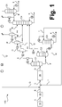
- FIG. 1 illustrates a method according to an embodiment of the invention.
- FIG. 1 a method according to an embodiment of the invention in the form of a simplified process flow diagram is illustrated schematically and designated overall by 100.
- a mass flow A is provided by means of one or more metallurgical processes, which are or will be denoted overall by 10 here.
- the stream A may also be suitably purified to obtain a purified stream B.
- the stream B in the embodiment illustrated here has a molar ratio of hydrogen to carbon monoxide of significantly less than 2, for example from 1 to 1.5 or 1.1 to 1.2, in particular about 1.15. Further possible values have already been explained.
- the purified stream B is combined in the example shown with two recirculated streams I and Q, whose composition is explained below.
- a feed stream C formed in this manner is fed to a direct dimethyl ether ether synthesis 30 using one or more reactors equipped with suitable catalysts.
- a crude product stream D is obtained, which, as not separately illustrated here, is cooled.
- the cooling can, for example, at least partially by a heat integration with one or more streams, such as the purified stream B or the feed stream C, are performed.
- the correspondingly cooled crude product stream D is fed into a first separation column C1.
- Top gas of the first separation column C1 is cooled and partially condensed.
- the condensed fraction of the top gas of the first separation column C1 is recycled as reflux to the first separation column C1.
- the uncondensed fraction of the top gas of the first separation column C1 is subjected in the form of a stream E to a gradual further cooling, as further explained below.
- Bottom liquid of the first separation column C1 is fed via a not separately designated valve in the form of a stream F of a second separation column C2.
- the liquid supplied in the form of the stream F of the second separation column contains predominantly or exclusively methanol and water, as well as dimethyl ether and further dissolved gases.
- the liquid fed into the second separation column C2 in the form of the material stream F is freed from dimethyl ether and further dissolved gases, which pass into a top gas of the second separation column.
- a bottoms liquid of the second separation column C2 therefore contains predominantly or exclusively methanol and water and possibly higher-boiling components. It is partially vaporized in a bottom evaporator and recycled in gaseous form into the second separation column C2.
- the top gas of the second separation column C2 is cooled and partially condensed. The condensed fraction of the top gas of the second separation column C2 is recycled as reflux to the second separation column C2.
- the noncondensed fraction of the top gas of the second separation column C2 is subjected to further separation in the form of a stream G, as further explained below.
- the Bottom liquid of the second separation column C2 or its portion not vaporized and returned to the second separation column C2 is fed via a not separately designated valve in the form of a stream H of a third separation column C3.
- the liquid fed into the third separation column C3 in the form of the stream H is separated into a head gas containing predominantly or exclusively methanol and a bottoms liquid containing predominantly or exclusively water. Also, heavier components may be included.
- the top gas of the third separation column C3 is cooled, condensed, and fed in part as reflux to the third separation column C3 and recycled to another part in the form of the already mentioned stream I in the process 100.
- the stream I can be brought to liquid pressure and evaporated.
- the bottom liquid of the third separation column C3 is vaporized in part in a bottom evaporator and recycled in gaseous form into the third separation column C3 and carried out partly in the form of a stream K from the process 100.
- top gas of the first separation column C1 contains predominantly or exclusively dimethyl ether, carbon dioxide and lower boiling dissolved gases, especially hydrogen and carbon monoxide, but is poor or free of water and methanol.
- the stream E is fed to a gradual cooling, wherein after each cooling stage in each of separators S1, S2 and S3 condensates deposited and withdrawn in the form of streams L, M and N from the separators S1, S2 and S3.
- more or fewer cooling and condensation steps can also be used.
- the remaining gaseous in the separators S1 and S2 shares are further cooled and supplied in the form of streams O and P respectively to the next separator S2 and S3.
- a fraction which remains gaseous also in the separator S3 is returned to the process 100 as part of the already mentioned material flow.
- Stream Q may be utilized for cold recovery in a heat exchanger not specifically referred to and is compressed to recycle it at a suitable pressure to the dimethyl ether direct synthesis.
- the provided in the form of the illustrated streams G, L, M and N, rich in dimethyl ether fluids, which also still carbon dioxide and lighter than carbon dioxide and lower boiling dissolved gases, especially hydrogen and carbon monoxide, but poor in or free of water and methanol are fed to separate DME a fourth separation column C4.
- a predominantly or exclusively dimethyl ether-containing bottoms liquid and a predominantly or exclusively carbon dioxide and lower-boiling gases, in particular hydrogen and carbon monoxide, containing overhead gas are formed.
- the top gas of the fourth separation column C4 is cooled and partially condensed.
- a condensed portion of the top gas of the fourth separation column C4 is partly fed as reflux to the fourth separation column C4 and fed to a part in the form of a stream R in a fifth separation column C5.
- An uncondensed portion of the top gas of the fourth separation column C4 is returned to the process 100 as part of the already mentioned material flow Q.
- the bottom liquid of the fourth separation column C4 is vaporized in part in a bottom evaporator and recycled in gaseous form into the fourth separation column C4 and carried out partly in the form of a stream S as dimethyl ether product from the process 100.
- the dimethyl ether product may in particular have fuel quality.
- the condensed overhead gas of the fourth separation column C4 fed into the fifth separation column C5 in the fifth separation column C5 is separated in the fifth separation column C5 into a bottoms liquid containing predominantly or exclusively carbon dioxide and a head gas containing predominantly or exclusively the lower boiling gases, in particular hydrogen and carbon monoxide ,
- the head gas can be recycled as part of the stream Q in the process 100. It may in particular be combined with the uncondensed fraction of the top gas of the fourth separation column C4 and compressed before it is combined with the gaseous fraction remaining in the separator S3.
- the bottom liquid of the fifth separation column C5 is partly vaporized in a bottom evaporator and recycled in gaseous form to the fifth separation column C5 and carried out partly in the form of a stream T as carbon dioxide product from the process 100.
- the fifth separation column C5 can be comparatively simple and have only a small number of separating trays. On a top condenser can be omitted. Nevertheless, using the fifth separation column C5 in the form of the stream T exported carbon dioxide product can be obtained in highly pure form and provided, for example, in food quality as so-called carbon dioxide 4.5.
- a corresponding purification can also be effected only by a relaxation with subsequent gas-liquid separation.
- the advantage of complete or near-complete removal of carbon dioxide while simultaneously providing an attractive carbon dioxide product can be achieved.
- the mentioned process conditions can be adjusted.
- a molar ratio of hydrogen to carbon monoxide in the range mentioned, in particular of approximately 1.5 can be set or increased to such a value.
Landscapes
- Chemical & Material Sciences (AREA)
- Organic Chemistry (AREA)
- Crystallography & Structural Chemistry (AREA)
- Organic Low-Molecular-Weight Compounds And Preparation Thereof (AREA)
Applications Claiming Priority (1)
| Application Number | Priority Date | Filing Date | Title |
|---|---|---|---|
| DE102017010788.2A DE102017010788A1 (de) | 2017-11-22 | 2017-11-22 | Verfahren und Anlage zur Gewinnung von Dimethylether und Kohlendioxid |
Publications (2)
| Publication Number | Publication Date |
|---|---|
| EP3521267A1 true EP3521267A1 (fr) | 2019-08-07 |
| EP3521267B1 EP3521267B1 (fr) | 2020-12-30 |
Family
ID=64401953
Family Applications (1)
| Application Number | Title | Priority Date | Filing Date |
|---|---|---|---|
| EP18020582.5A Active EP3521267B1 (fr) | 2017-11-22 | 2018-11-07 | Procédé d'obtention de diméthyléther et de dioxyde de carbone |
Country Status (6)
| Country | Link |
|---|---|
| EP (1) | EP3521267B1 (fr) |
| CN (1) | CN109809963A (fr) |
| DE (1) | DE102017010788A1 (fr) |
| ES (1) | ES2856258T3 (fr) |
| RU (1) | RU2018140857A (fr) |
| ZA (1) | ZA201807845B (fr) |
Cited By (2)
| Publication number | Priority date | Publication date | Assignee | Title |
|---|---|---|---|---|
| EP4276086A1 (fr) | 2022-05-10 | 2023-11-15 | Linde GmbH | Procédé et installation de production d'éther diméthylique |
| EP4311824A1 (fr) | 2022-07-25 | 2024-01-31 | Linde GmbH | Procédé et installation de production d'éther diméthylique |
Families Citing this family (2)
| Publication number | Priority date | Publication date | Assignee | Title |
|---|---|---|---|---|
| CA3203689A1 (fr) | 2021-01-15 | 2022-07-21 | Ingi Mar JONSSON | Reacteur de synthese du methanol |
| EP4116285A1 (fr) | 2021-07-08 | 2023-01-11 | Linde GmbH | Procédé et installation de production d'éther diméthylique |
Citations (3)
| Publication number | Priority date | Publication date | Assignee | Title |
|---|---|---|---|---|
| WO2015104290A1 (fr) * | 2014-01-07 | 2015-07-16 | Linde Aktiengesellschaft | Traitement séparatif d'un mélange gazeux formé à partir d'un courant de produit d'un réacteur de production de diméthyléther |
| WO2015104238A1 (fr) | 2014-01-07 | 2015-07-16 | Linde Aktiengesellschaft | Procédé de traitement séparatif d'un courant de produit d'un réacteur de production de diméthyléther |
| WO2015106952A1 (fr) * | 2014-01-16 | 2015-07-23 | Linde Aktiengesellschaft | Procédé et dispositif de production de diméthyle éther |
Family Cites Families (2)
| Publication number | Priority date | Publication date | Assignee | Title |
|---|---|---|---|---|
| CN1190405C (zh) * | 2002-05-15 | 2005-02-23 | 中国科学院工程热物理研究所 | 精制二甲醚同时回收二氧化碳的分离工艺 |
| EP2898943B1 (fr) * | 2014-01-28 | 2016-11-16 | Linde Aktiengesellschaft | Porcédé et dispositif pur l'obtention du dimethyléther à partir du gaz de synthèse |
-
2017
- 2017-11-22 DE DE102017010788.2A patent/DE102017010788A1/de not_active Withdrawn
-
2018
- 2018-11-07 EP EP18020582.5A patent/EP3521267B1/fr active Active
- 2018-11-07 ES ES18020582T patent/ES2856258T3/es active Active
- 2018-11-20 RU RU2018140857A patent/RU2018140857A/ru unknown
- 2018-11-21 ZA ZA2018/07845A patent/ZA201807845B/en unknown
- 2018-11-22 CN CN201811397720.0A patent/CN109809963A/zh active Pending
Patent Citations (3)
| Publication number | Priority date | Publication date | Assignee | Title |
|---|---|---|---|---|
| WO2015104290A1 (fr) * | 2014-01-07 | 2015-07-16 | Linde Aktiengesellschaft | Traitement séparatif d'un mélange gazeux formé à partir d'un courant de produit d'un réacteur de production de diméthyléther |
| WO2015104238A1 (fr) | 2014-01-07 | 2015-07-16 | Linde Aktiengesellschaft | Procédé de traitement séparatif d'un courant de produit d'un réacteur de production de diméthyléther |
| WO2015106952A1 (fr) * | 2014-01-16 | 2015-07-23 | Linde Aktiengesellschaft | Procédé et dispositif de production de diméthyle éther |
Non-Patent Citations (4)
| Title |
|---|
| "CHEMYSTEMS PERP Program", November 2008, NEXANT INC., article "Dimethyl Ether Technology and Markets" |
| "DME Handbook des Japan DME Forum", 2007 |
| LEE, S.-H.: "Scale Up Study of DME Direct Synthesis Technology", PROCEEDINGS OF THE 24TH WORLD GAS CONFERENCE, 2009 |
| OGAWA, T. ET AL.: "Direct Dimethyl Ether Synthesis", J. NAT. GAS CHEM., vol. 12, 2003, pages 219 - 227 |
Cited By (3)
| Publication number | Priority date | Publication date | Assignee | Title |
|---|---|---|---|---|
| EP4276086A1 (fr) | 2022-05-10 | 2023-11-15 | Linde GmbH | Procédé et installation de production d'éther diméthylique |
| WO2023217408A1 (fr) | 2022-05-10 | 2023-11-16 | Linde Gmbh | Procédé et système de préparation d'éther diméthylique |
| EP4311824A1 (fr) | 2022-07-25 | 2024-01-31 | Linde GmbH | Procédé et installation de production d'éther diméthylique |
Also Published As
| Publication number | Publication date |
|---|---|
| RU2018140857A (ru) | 2020-05-20 |
| ZA201807845B (en) | 2019-08-28 |
| ES2856258T3 (es) | 2021-09-27 |
| CN109809963A (zh) | 2019-05-28 |
| EP3521267B1 (fr) | 2020-12-30 |
| DE102017010788A1 (de) | 2019-05-23 |
Similar Documents
| Publication | Publication Date | Title |
|---|---|---|
| EP3521267B1 (fr) | Procédé d'obtention de diméthyléther et de dioxyde de carbone | |
| EP3847146B1 (fr) | Procédé de production de méthanol à partir de gaz de synthèse sans émission de dioxyde de carbone | |
| EP2094371A1 (fr) | Procédé de récupération de dioxyde de carbone | |
| DE2824840A1 (de) | Integriertes verfahren zur teiloxidation und thermischen krackung | |
| EP3092054B1 (fr) | Traitement de séparation d'un mélange gazeux constitué d'un flux de produit d'un réacteur à diméthyléther | |
| EP3558912B1 (fr) | Procédé et installation de production d'une oléfine | |
| EP3092053B1 (fr) | Procédé de séparation d'un flux de produit d'un réacteur à diméthyléther | |
| WO2017088981A1 (fr) | Procédé et dispositif de séparation du dioxyde de carbone à partir d'un gaz de synthèse | |
| EP3102309B1 (fr) | Méthode pour produire des composes à poids moléculaire élevés en utilisant un tsa-co2 indirectement chauffé | |
| EP2898943B1 (fr) | Porcédé et dispositif pur l'obtention du dimethyléther à partir du gaz de synthèse | |
| DE102018003343A1 (de) | Verfahren und Anlage zur Herstellung von Ethanol | |
| EP3020696B1 (fr) | Procede de fabrication d'un ou plusieurs produits de reaction | |
| WO2022042875A1 (fr) | Procédé et installation de préparation d'éther diméthylique | |
| DE3220995A1 (de) | Verfahren zur gewinnung von methanol | |
| EP4311824A1 (fr) | Procédé et installation de production d'éther diméthylique | |
| EP2913320A1 (fr) | Procédé et installation de collecte de produits oxygénés avec un échange de chaleur continu entre le flux d'alimentation et le flux de produit brut | |
| EP4276086A1 (fr) | Procédé et installation de production d'éther diméthylique | |
| WO2009130046A2 (fr) | Traitement de gaz de recyclage pour la transformation thermochimique directe de substances organiques de poids moléculaire élevé en matières premières, combustibles et carburants liquides peu visqueux | |
| DE2655132A1 (de) | Verfahren zum erzeugen von ersatzerdgas | |
| DE102016204331A1 (de) | Verfahren zur Herstellung von Ammoniak aus Rohgas | |
| EP4083258A1 (fr) | Procédé et installation de production d'hydrocarbures | |
| WO2023011753A1 (fr) | Procédé et installation de préparation d'éther diméthylique | |
| DE3345027A1 (de) | Verfahren zur aufbereitung von synthesegasen | |
| EP4066921A1 (fr) | Procédé et installation de production de méthanol et d'ammoniaque | |
| DE3244302A1 (de) | Verfahren zur herstellung von methanol |
Legal Events
| Date | Code | Title | Description |
|---|---|---|---|
| PUAI | Public reference made under article 153(3) epc to a published international application that has entered the european phase |
Free format text: ORIGINAL CODE: 0009012 |
|
| STAA | Information on the status of an ep patent application or granted ep patent |
Free format text: STATUS: THE APPLICATION HAS BEEN PUBLISHED |
|
| AK | Designated contracting states |
Kind code of ref document: A1 Designated state(s): AL AT BE BG CH CY CZ DE DK EE ES FI FR GB GR HR HU IE IS IT LI LT LU LV MC MK MT NL NO PL PT RO RS SE SI SK SM TR |
|
| AX | Request for extension of the european patent |
Extension state: BA ME |
|
| STAA | Information on the status of an ep patent application or granted ep patent |
Free format text: STATUS: REQUEST FOR EXAMINATION WAS MADE |
|
| 17P | Request for examination filed |
Effective date: 20200205 |
|
| RBV | Designated contracting states (corrected) |
Designated state(s): AL AT BE BG CH CY CZ DE DK EE ES FI FR GB GR HR HU IE IS IT LI LT LU LV MC MK MT NL NO PL PT RO RS SE SI SK SM TR |
|
| RAP1 | Party data changed (applicant data changed or rights of an application transferred) |
Owner name: LINDE GMBH |
|
| GRAP | Despatch of communication of intention to grant a patent |
Free format text: ORIGINAL CODE: EPIDOSNIGR1 |
|
| STAA | Information on the status of an ep patent application or granted ep patent |
Free format text: STATUS: GRANT OF PATENT IS INTENDED |
|
| RIC1 | Information provided on ipc code assigned before grant |
Ipc: C07C 41/42 20060101ALI20200925BHEP Ipc: C07C 43/04 20060101ALI20200925BHEP Ipc: C07C 41/01 20060101AFI20200925BHEP Ipc: C07C 31/04 20060101ALI20200925BHEP Ipc: C07C 41/09 20060101ALI20200925BHEP Ipc: C07C 29/151 20060101ALI20200925BHEP Ipc: C07C 29/15 20060101ALI20200925BHEP |
|
| INTG | Intention to grant announced |
Effective date: 20201014 |
|
| GRAS | Grant fee paid |
Free format text: ORIGINAL CODE: EPIDOSNIGR3 |
|
| GRAA | (expected) grant |
Free format text: ORIGINAL CODE: 0009210 |
|
| STAA | Information on the status of an ep patent application or granted ep patent |
Free format text: STATUS: THE PATENT HAS BEEN GRANTED |
|
| AK | Designated contracting states |
Kind code of ref document: B1 Designated state(s): AL AT BE BG CH CY CZ DE DK EE ES FI FR GB GR HR HU IE IS IT LI LT LU LV MC MK MT NL NO PL PT RO RS SE SI SK SM TR |
|
| REG | Reference to a national code |
Ref country code: GB Ref legal event code: FG4D Free format text: NOT ENGLISH |
|
| REG | Reference to a national code |
Ref country code: AT Ref legal event code: REF Ref document number: 1349792 Country of ref document: AT Kind code of ref document: T Effective date: 20210115 |
|
| REG | Reference to a national code |
Ref country code: DE Ref legal event code: R096 Ref document number: 502018003423 Country of ref document: DE |
|
| REG | Reference to a national code |
Ref country code: IE Ref legal event code: FG4D Free format text: LANGUAGE OF EP DOCUMENT: GERMAN |
|
| PG25 | Lapsed in a contracting state [announced via postgrant information from national office to epo] |
Ref country code: GR Free format text: LAPSE BECAUSE OF FAILURE TO SUBMIT A TRANSLATION OF THE DESCRIPTION OR TO PAY THE FEE WITHIN THE PRESCRIBED TIME-LIMIT Effective date: 20210331 Ref country code: NO Free format text: LAPSE BECAUSE OF FAILURE TO SUBMIT A TRANSLATION OF THE DESCRIPTION OR TO PAY THE FEE WITHIN THE PRESCRIBED TIME-LIMIT Effective date: 20210330 Ref country code: FI Free format text: LAPSE BECAUSE OF FAILURE TO SUBMIT A TRANSLATION OF THE DESCRIPTION OR TO PAY THE FEE WITHIN THE PRESCRIBED TIME-LIMIT Effective date: 20201230 Ref country code: RS Free format text: LAPSE BECAUSE OF FAILURE TO SUBMIT A TRANSLATION OF THE DESCRIPTION OR TO PAY THE FEE WITHIN THE PRESCRIBED TIME-LIMIT Effective date: 20201230 |
|
| PG25 | Lapsed in a contracting state [announced via postgrant information from national office to epo] |
Ref country code: BG Free format text: LAPSE BECAUSE OF FAILURE TO SUBMIT A TRANSLATION OF THE DESCRIPTION OR TO PAY THE FEE WITHIN THE PRESCRIBED TIME-LIMIT Effective date: 20210330 Ref country code: SE Free format text: LAPSE BECAUSE OF FAILURE TO SUBMIT A TRANSLATION OF THE DESCRIPTION OR TO PAY THE FEE WITHIN THE PRESCRIBED TIME-LIMIT Effective date: 20201230 Ref country code: LV Free format text: LAPSE BECAUSE OF FAILURE TO SUBMIT A TRANSLATION OF THE DESCRIPTION OR TO PAY THE FEE WITHIN THE PRESCRIBED TIME-LIMIT Effective date: 20201230 |
|
| REG | Reference to a national code |
Ref country code: NL Ref legal event code: MP Effective date: 20201230 |
|
| PG25 | Lapsed in a contracting state [announced via postgrant information from national office to epo] |
Ref country code: HR Free format text: LAPSE BECAUSE OF FAILURE TO SUBMIT A TRANSLATION OF THE DESCRIPTION OR TO PAY THE FEE WITHIN THE PRESCRIBED TIME-LIMIT Effective date: 20201230 |
|
| REG | Reference to a national code |
Ref country code: LT Ref legal event code: MG9D |
|
| PG25 | Lapsed in a contracting state [announced via postgrant information from national office to epo] |
Ref country code: RO Free format text: LAPSE BECAUSE OF FAILURE TO SUBMIT A TRANSLATION OF THE DESCRIPTION OR TO PAY THE FEE WITHIN THE PRESCRIBED TIME-LIMIT Effective date: 20201230 Ref country code: PT Free format text: LAPSE BECAUSE OF FAILURE TO SUBMIT A TRANSLATION OF THE DESCRIPTION OR TO PAY THE FEE WITHIN THE PRESCRIBED TIME-LIMIT Effective date: 20210430 Ref country code: SK Free format text: LAPSE BECAUSE OF FAILURE TO SUBMIT A TRANSLATION OF THE DESCRIPTION OR TO PAY THE FEE WITHIN THE PRESCRIBED TIME-LIMIT Effective date: 20201230 Ref country code: EE Free format text: LAPSE BECAUSE OF FAILURE TO SUBMIT A TRANSLATION OF THE DESCRIPTION OR TO PAY THE FEE WITHIN THE PRESCRIBED TIME-LIMIT Effective date: 20201230 Ref country code: CZ Free format text: LAPSE BECAUSE OF FAILURE TO SUBMIT A TRANSLATION OF THE DESCRIPTION OR TO PAY THE FEE WITHIN THE PRESCRIBED TIME-LIMIT Effective date: 20201230 Ref country code: LT Free format text: LAPSE BECAUSE OF FAILURE TO SUBMIT A TRANSLATION OF THE DESCRIPTION OR TO PAY THE FEE WITHIN THE PRESCRIBED TIME-LIMIT Effective date: 20201230 |
|
| PG25 | Lapsed in a contracting state [announced via postgrant information from national office to epo] |
Ref country code: PL Free format text: LAPSE BECAUSE OF FAILURE TO SUBMIT A TRANSLATION OF THE DESCRIPTION OR TO PAY THE FEE WITHIN THE PRESCRIBED TIME-LIMIT Effective date: 20201230 |
|
| REG | Reference to a national code |
Ref country code: ES Ref legal event code: FG2A Ref document number: 2856258 Country of ref document: ES Kind code of ref document: T3 Effective date: 20210927 |
|
| PG25 | Lapsed in a contracting state [announced via postgrant information from national office to epo] |
Ref country code: IS Free format text: LAPSE BECAUSE OF FAILURE TO SUBMIT A TRANSLATION OF THE DESCRIPTION OR TO PAY THE FEE WITHIN THE PRESCRIBED TIME-LIMIT Effective date: 20210430 |
|
| REG | Reference to a national code |
Ref country code: DE Ref legal event code: R097 Ref document number: 502018003423 Country of ref document: DE |
|
| PG25 | Lapsed in a contracting state [announced via postgrant information from national office to epo] |
Ref country code: AL Free format text: LAPSE BECAUSE OF FAILURE TO SUBMIT A TRANSLATION OF THE DESCRIPTION OR TO PAY THE FEE WITHIN THE PRESCRIBED TIME-LIMIT Effective date: 20201230 |
|
| PLBE | No opposition filed within time limit |
Free format text: ORIGINAL CODE: 0009261 |
|
| STAA | Information on the status of an ep patent application or granted ep patent |
Free format text: STATUS: NO OPPOSITION FILED WITHIN TIME LIMIT |
|
| PG25 | Lapsed in a contracting state [announced via postgrant information from national office to epo] |
Ref country code: DK Free format text: LAPSE BECAUSE OF FAILURE TO SUBMIT A TRANSLATION OF THE DESCRIPTION OR TO PAY THE FEE WITHIN THE PRESCRIBED TIME-LIMIT Effective date: 20201230 |
|
| 26N | No opposition filed |
Effective date: 20211001 |
|
| PG25 | Lapsed in a contracting state [announced via postgrant information from national office to epo] |
Ref country code: SI Free format text: LAPSE BECAUSE OF FAILURE TO SUBMIT A TRANSLATION OF THE DESCRIPTION OR TO PAY THE FEE WITHIN THE PRESCRIBED TIME-LIMIT Effective date: 20201230 |
|
| PG25 | Lapsed in a contracting state [announced via postgrant information from national office to epo] |
Ref country code: IS Free format text: LAPSE BECAUSE OF FAILURE TO SUBMIT A TRANSLATION OF THE DESCRIPTION OR TO PAY THE FEE WITHIN THE PRESCRIBED TIME-LIMIT Effective date: 20210430 |
|
| PG25 | Lapsed in a contracting state [announced via postgrant information from national office to epo] |
Ref country code: MC Free format text: LAPSE BECAUSE OF FAILURE TO SUBMIT A TRANSLATION OF THE DESCRIPTION OR TO PAY THE FEE WITHIN THE PRESCRIBED TIME-LIMIT Effective date: 20201230 |
|
| REG | Reference to a national code |
Ref country code: CH Ref legal event code: PL |
|
| PG25 | Lapsed in a contracting state [announced via postgrant information from national office to epo] |
Ref country code: LU Free format text: LAPSE BECAUSE OF NON-PAYMENT OF DUE FEES Effective date: 20211107 Ref country code: BE Free format text: LAPSE BECAUSE OF NON-PAYMENT OF DUE FEES Effective date: 20211130 |
|
| REG | Reference to a national code |
Ref country code: BE Ref legal event code: MM Effective date: 20211130 |
|
| PG25 | Lapsed in a contracting state [announced via postgrant information from national office to epo] |
Ref country code: LI Free format text: LAPSE BECAUSE OF NON-PAYMENT OF DUE FEES Effective date: 20211130 Ref country code: CH Free format text: LAPSE BECAUSE OF NON-PAYMENT OF DUE FEES Effective date: 20211130 |
|
| PG25 | Lapsed in a contracting state [announced via postgrant information from national office to epo] |
Ref country code: IE Free format text: LAPSE BECAUSE OF NON-PAYMENT OF DUE FEES Effective date: 20211107 |
|
| PGFP | Annual fee paid to national office [announced via postgrant information from national office to epo] |
Ref country code: IT Payment date: 20221130 Year of fee payment: 5 Ref country code: GB Payment date: 20221123 Year of fee payment: 5 Ref country code: FR Payment date: 20221118 Year of fee payment: 5 Ref country code: ES Payment date: 20221216 Year of fee payment: 5 Ref country code: DE Payment date: 20221121 Year of fee payment: 5 |
|
| PG25 | Lapsed in a contracting state [announced via postgrant information from national office to epo] |
Ref country code: NL Free format text: LAPSE BECAUSE OF NON-PAYMENT OF DUE FEES Effective date: 20201230 Ref country code: CY Free format text: LAPSE BECAUSE OF FAILURE TO SUBMIT A TRANSLATION OF THE DESCRIPTION OR TO PAY THE FEE WITHIN THE PRESCRIBED TIME-LIMIT Effective date: 20201230 |
|
| PG25 | Lapsed in a contracting state [announced via postgrant information from national office to epo] |
Ref country code: SM Free format text: LAPSE BECAUSE OF FAILURE TO SUBMIT A TRANSLATION OF THE DESCRIPTION OR TO PAY THE FEE WITHIN THE PRESCRIBED TIME-LIMIT Effective date: 20201230 Ref country code: HU Free format text: LAPSE BECAUSE OF FAILURE TO SUBMIT A TRANSLATION OF THE DESCRIPTION OR TO PAY THE FEE WITHIN THE PRESCRIBED TIME-LIMIT; INVALID AB INITIO Effective date: 20181107 |
|
| PG25 | Lapsed in a contracting state [announced via postgrant information from national office to epo] |
Ref country code: MK Free format text: LAPSE BECAUSE OF FAILURE TO SUBMIT A TRANSLATION OF THE DESCRIPTION OR TO PAY THE FEE WITHIN THE PRESCRIBED TIME-LIMIT Effective date: 20201230 |