EP3521106B1 - Behälter für kraftfahrzeuge zur aufnahme und zum transport von paletten - Google Patents
Behälter für kraftfahrzeuge zur aufnahme und zum transport von paletten Download PDFInfo
- Publication number
- EP3521106B1 EP3521106B1 EP18155315.7A EP18155315A EP3521106B1 EP 3521106 B1 EP3521106 B1 EP 3521106B1 EP 18155315 A EP18155315 A EP 18155315A EP 3521106 B1 EP3521106 B1 EP 3521106B1
- Authority
- EP
- European Patent Office
- Prior art keywords
- container
- side wall
- piece
- cross
- stop means
- Prior art date
- Legal status (The legal status is an assumption and is not a legal conclusion. Google has not performed a legal analysis and makes no representation as to the accuracy of the status listed.)
- Active
Links
Images

Classifications
-
- B—PERFORMING OPERATIONS; TRANSPORTING
- B60—VEHICLES IN GENERAL
- B60R—VEHICLES, VEHICLE FITTINGS, OR VEHICLE PARTS, NOT OTHERWISE PROVIDED FOR
- B60R9/00—Supplementary fittings on vehicle exterior for carrying loads, e.g. luggage, sports gear or the like
- B60R9/02—Supplementary fittings on vehicle exterior for carrying loads, e.g. luggage, sports gear or the like at the sides, e.g. on running-board
-
- B—PERFORMING OPERATIONS; TRANSPORTING
- B65—CONVEYING; PACKING; STORING; HANDLING THIN OR FILAMENTARY MATERIAL
- B65D—CONTAINERS FOR STORAGE OR TRANSPORT OF ARTICLES OR MATERIALS, e.g. BAGS, BARRELS, BOTTLES, BOXES, CANS, CARTONS, CRATES, DRUMS, JARS, TANKS, HOPPERS, FORWARDING CONTAINERS; ACCESSORIES, CLOSURES, OR FITTINGS THEREFOR; PACKAGING ELEMENTS; PACKAGES
- B65D19/00—Pallets or like platforms, with or without side walls, for supporting loads to be lifted or lowered
- B65D19/38—Details or accessories
- B65D19/385—Frames, corner posts or pallet converters, e.g. for facilitating stacking of charged pallets
-
- B—PERFORMING OPERATIONS; TRANSPORTING
- B65—CONVEYING; PACKING; STORING; HANDLING THIN OR FILAMENTARY MATERIAL
- B65D—CONTAINERS FOR STORAGE OR TRANSPORT OF ARTICLES OR MATERIALS, e.g. BAGS, BARRELS, BOTTLES, BOXES, CANS, CARTONS, CRATES, DRUMS, JARS, TANKS, HOPPERS, FORWARDING CONTAINERS; ACCESSORIES, CLOSURES, OR FITTINGS THEREFOR; PACKAGING ELEMENTS; PACKAGES
- B65D21/00—Nestable, stackable or joinable containers; Containers of variable capacity
- B65D21/02—Containers specially shaped, or provided with fittings or attachments, to facilitate nesting, stacking, or joining together
- B65D21/0201—Containers specially shaped, or provided with fittings or attachments, to facilitate nesting, stacking, or joining together stackable or joined together side-by-side
- B65D21/0204—Containers specially shaped, or provided with fittings or attachments, to facilitate nesting, stacking, or joining together stackable or joined together side-by-side and joined together by interconnecting formations forming part of the container, e.g. dove-tail, snap connections, hook elements
-
- B—PERFORMING OPERATIONS; TRANSPORTING
- B65—CONVEYING; PACKING; STORING; HANDLING THIN OR FILAMENTARY MATERIAL
- B65D—CONTAINERS FOR STORAGE OR TRANSPORT OF ARTICLES OR MATERIALS, e.g. BAGS, BARRELS, BOTTLES, BOXES, CANS, CARTONS, CRATES, DRUMS, JARS, TANKS, HOPPERS, FORWARDING CONTAINERS; ACCESSORIES, CLOSURES, OR FITTINGS THEREFOR; PACKAGING ELEMENTS; PACKAGES
- B65D7/00—Containers having bodies formed by interconnecting or uniting two or more rigid, or substantially rigid, components made wholly or mainly of metal
- B65D7/02—Containers having bodies formed by interconnecting or uniting two or more rigid, or substantially rigid, components made wholly or mainly of metal characterised by shape
- B65D7/06—Containers having bodies formed by interconnecting or uniting two or more rigid, or substantially rigid, components made wholly or mainly of metal characterised by shape of polygonal cross-section, e.g. tins, boxes
Definitions
- the invention relates to a container for motor vehicles for receiving and transporting goods, in particular pallets, with a cuboid casing body that can be closed with at least one lid and consists of side walls extending over the depth of the container, with a container base connecting the side walls and with a side walls connecting upper container part, the casing body being assigned stop means.
- Such containers are storage containers which are usually fastened in a suitable manner under the main frame of vehicles, in particular trucks, semi-trailers, trailers or the like. In this additional storage space, Euro pallets or other goods can be transported without reducing the actual loading space of the vehicle.
- the containers should be as light and robust as possible and be integratable into the vehicle. These containers can be attached both in front of the axles of the vehicle and between and / or behind the axles.
- the containers are fastened in particular by means of screws, clamps, beam clamps or the like and bores in the casing of the storage box, in particular in the side walls and / or in the upper part of the container directly or indirectly on the frame of the vehicle.
- the seal is inadequate or damaged, water and dirt can penetrate the container through said holes in the jacket for fastening.
- the assembly must be carried out from inside the container, which in practice is cumbersome and difficult. Due to aggressive environmental influences (salt, sand, water, etc.), permanent sealing of the relevant bores is only possible to a limited extent and is hardly possible in a satisfactory manner.
- the document DE9110254 U1 discloses a container according to the preamble of claim 1.
- the invention is therefore based on the object of avoiding the aforementioned disadvantages and of specifying a container which can not only be securely attached to the vehicle, but in which the penetration of liquids through the container jacket is also reliably prevented. In addition, it should be possible to easily assemble the storage box from the outside.
- the invention solves the problem in that along the longitudinal edge of the side wall on the upper side of the container, an edge section protruding towards the inside of the container is provided, which on the upper side of the container merges into a web whose edge section width corresponds to the recess depth and that the stop means are assigned to the web.
- the end of the web can merge into a flank pointing towards the side wall and plane-parallel to the side wall. This results in a stiffening of the container jacket and also the possibility of a particularly advantageous cover storage or an attachment option for other attachments.
- the cover can be displaced in a guide between an open and a closed position, which is arranged on the flank, said guide is also attached to the container jacket in such a way that liquids are reliably prevented from penetrating through the container jacket from this side as well.
- the guide a guide plate, guide profile or the like with the flank screwed, riveted or otherwise fastened and also mountable from the outside on the casing body.
- the connecting profiles can have any suitable shape, that is, they can be designed as an edge profile, an extruded profile or a rolled profile. In the following exemplary embodiment, the connecting profiles are fishhook-shaped.
- the dimensions of the connection profile are variable according to the technical possibilities and requirements of the connection profile.
- the connecting profile stiffens the container, simplifies its assembly and is part of a particularly robust stop for the container itself, for guiding the lid and / or for other attachments.
- the connecting profile integrated into the container is preferably designed as a combination profile and serves on the one hand to attach the container to the frame of the vehicle and on the other hand also as a holder for the cover guide or various add-on parts.
- the invention relates to a container 1 for motor vehicles for receiving and transporting pallets 2, with a cuboid casing body 4, which can be closed with at least one cover 3, extending over the depth of the container extending side walls 5, with a container bottom 6 connecting the side walls 5 and with an upper container part 7 connecting the side walls 5, the casing body 4 being assigned stop means 8.
- the container 1 is fastened via the stop means 8, for example, to the frame of a vehicle (not shown) and in particular is screwed, riveted or connected in any other suitable manner to the frame, a fastening bracket or the like.
- an edge section 10 Provided along the longitudinal edge of the side wall 5 on the upper side of the container is an edge section 10, a type of fold, which protrudes towards the interior of the container 9 and which merges into a web 11 on the upper side of the container, the edge section width 12 of which corresponds to the recess depth.
- the stop means 8 are holes which break through the web 11 and into which screws, rivets or the like can be inserted for fastening the container 1 to the motor vehicle.
- the end of the web 11 merges into a flank 13 pointing towards the side wall 5 and plane-parallel to the side wall 5, with which the side wall is stiffened.
- the cover 3 can be displaced in a guide 14 between an open and a closed position, which is arranged and fastened on the flank 13.
- the longitudinal edge of the side wall 5 on the side of the upper part of the container and the longitudinal edge of the upper part 7, which forms the web 11 and extends over the depth of the container, are connected via a connecting profile 15, to which stop means 8 in the form of connecting profile 15 and web 11 are assigned through holes.
Landscapes
- Engineering & Computer Science (AREA)
- Mechanical Engineering (AREA)
- Pallets (AREA)
Description
- Die Erfindung bezieht sich auf einen Behälter für Kraftfahrzeuge zur Aufnahme und zum Transport von Gütern, insbesondere Paletten, mit einem, mit wenigstens einem Deckel verschließbaren, quaderförmigen Mantelkörper aus sich über die Behältertiefe ersteckenden Seitenwänden, mit einem die Seitenwände verbindenden Behälterboden und mit einem die Seitenwände verbindenden Behälteroberteil, wobei dem Mantelkörper Anschlagmittel zugeordnet sind.
- Bei derartigen Behältern, insbesondere Palettenstaukästen, handelt es sich um Staubehälter welche üblicherweise unter dem Hauptrahmen von Fahrzeugen, insbesondere Lastkraftfahrzeugen, Sattelauflieger, Anhänger od. dgl., in geeigneter Weise befestigt werden. In diesem zusätzlichen Stauraum können Europaletten oder andere Güter transportiert werden, ohne den eigentlichen Laderaum des Fahrzeuges zu verringern. Die Behälter sollen möglichst leicht und robust, sowie in das Fahrzeug integrierbar sein. Diese Behälter können sowohl vor den Achsen des Fahrzeuges, als auch zwischen und/oder hinter den Achsen angebracht sein.
- Die Befestigung der Behälter erfolgt insbesondere mittels Schrauben, Spannpratzen, Trägerklemmen od. dgl. und Bohrungen im Mantel des Staukastens, insbesondere in Seitenwänden und/oder im Behälteroberteil mittelbar oder unmittelbar am Rahmen des Fahrzeuges. Durch besagte Bohrungen im Mantel für die Befestigung können allerdings bei mangelhafter oder beschädigter Abdichtung Wasser und Schmutz in den Behälter eindringen. Zudem muss die Montage über das Behälterinnere her erfolgen, was sich in der Praxis als umständlich und schwierig darstellt. Dauerhafte Abdichtungen der betreffenden Bohrungen sind aufgrund aggressiver Umwelteinflüsse (Salz, Sand, Wasser etc.) nur bedingt und kaum befriedigend möglich. Das Dokument
DE9110254 U1 offenbart einen Behälter nach dem Oberbegriff des Anspruchs 1. - Der Erfindung liegt somit die Aufgabe zugrunde, die vorgenannten Nachteile zu vermeiden und einen Behälter anzugeben, der nicht nur sicher am Fahrzeug festlegbar ist, sondern bei dem auch ein Eindringen von Flüssigkeiten durch den Behältermantel sicher vermieden wird. Zudem soll eine einfache Montage des Staukastens von außen möglich sein.
- Die Erfindung löst die gestellte Aufgabe dadurch, dass entlang des behälteroberteilseitigen Längsrandes der Seitenwand ein gegen das Behälterinnere vorspringender Randabschnitt vorgesehen ist, der behälteroberteilseitig in einen Steg übergeht, dessen Randabschnittbreite der Einsprungtiefe entspricht und dass die Anschlagmittel dem Steg zugeordnet sind.
- Damit ist es möglich einen Behälter anzugeben, der nicht nur sicher am Fahrzeug festlegbar ist, sondern bei dem auch ein Eindringen von Flüssigkeiten durch den Behältermantel sicher vermieden werden kann, da die Anschlagmittel, also beispielsweise Löcher oder Langlöcher dem jeweiligen Steg zugeordnet sind und somit wieder ins freie an der Seitenwandaußenfläche münden und nicht in das Behälterinnere. Eine Abdichtung der Anschlagmittel ist somit nicht notwendig. Zudem ist damit eine einfache Montage des Staukastens von außen möglich, da Anschlagmittel, wie Schrauben oder Nieten, von der Behälterau-ßenseite her zugänglich sind.
- Der Steg kann endseitig in eine zur Seitenwand hinweisende, zur Seitenwand planparallele Flanke übergehen. Damit ergibt sich eine Aussteifung des Behältermantels und zudem die Möglichkeit einer besonders vorteilhaften Deckellagerung oder eine Befestigungsmöglichkeit für andere Anbauteile.
- Ist der Deckel in einer Führung zwischen einer Offen- und einer Geschlossenlage verlagerbar, die an der Flanke angeordnet ist, so ist auch die besagte Führung derart am Behältermantel befestigt, dass auch von dieser Seite her ein Eindringen von Flüssigkeiten durch den Behältermantel sicher unterbunden wird. Dazu ist die Führung, ein Führungsblech, -profil od. dgl. mit der Flanke verschraubt, vernietet oder anderweitig befestigt und dabei ebenfalls von außen am Mantelkörper montierbar.
- Besonders vorteilhaft ist es, wenn der behälteroberteilseitige Längsrand der Seitenwand und der den Steg bildende Längsrand des Behälteroberteils über ein Verbindungsprofil verbunden sind, dem vorzugsweise ebenfalls Anschlagmittel in Form von Verbindungsprofil und Steg durchbrechender Löcher zugeordnet sind. Die Verbindungsprofile können jegliche geeignete Form haben, also als Kantprofil, als Strangpressprofil oder Walzprofil ausgeführt sein. Im folgenden Ausführungsbeispiel sind die Verbindungsprofile Angelhakenförmig ausgebildet. Die Abmessungen des Verbindungsprofils sind nach Maßgabe der technischen Möglichkeiten und Anforderungen an das Verbindungsprofil variabel. Das Verbindungsprofil steift den Behälter aus, vereinfacht dessen Montage und ist Teil eines besonders robusten Anschlages für den Behälter selbst, für die Führung des Deckels und/oder für andere Anbauteile. Das in den Behälter integrierte Verbindungsprofil ist vorzugsweise als Kombiprofil ausgeführt und dient einerseits der Befestigung des Behälters am Rahmen des Fahrzeuges und anderseits zusätzlich als Halterung für die Deckelführung bzw. diverser Anbauteile.
- In der Zeichnung ist der Erfindungsgegenstand beispielsweise dargestellt. Es zeigen
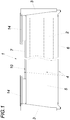
- Fig. 1
- einen Behälter für Kraftfahrzeuge zur Aufnahme und zum Transport von Paletten in Seitenansicht,
- Fig. 2
- den Behälter aus
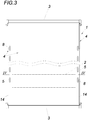
Fig. 1 in Vorderansicht, - Fig. 3
- den Behälter aus
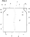
Fig. 1 in Draufsicht, - Fig. 4
- den Behälter aus
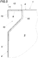
Fig. 3 im Schnitt nach der Linie IV-IV und - Fig. 5
- den linken oberen Eckbereich des Behälters aus
Fig. 4 in vergrößertem Maßstab. - Die Erfindung betrifft einen Behälter 1 für Kraftfahrzeuge zur Aufnahme und zum Transport von Paletten 2, mit einem, mit wenigstens einem Deckel 3 verschließbaren, quaderförmigen Mantelkörper 4 aus sich über die Behältertiefe ersteckenden Seitenwänden 5, mit einem die Seitenwände 5 verbindenden Behälterboden 6 und mit einem die Seitenwände 5 verbindenden Behälteroberteil 7, wobei dem Mantelkörper 4 Anschlagmittel 8 zugeordnet sind. Der Behälter 1 ist über die Anschlagmittel 8 beispielsweise am Rahmen eines nicht dargestellten Fahrzeuges befestigt und hierbei insbesondere mit dem Rahmen, einer Befestigungskonsole od. dgl. verschraubt, vernietet oder in sonstiger geeigneter Weise verbunden.
- Entlang des behälteroberteilseitigen Längsrandes der Seitenwand 5 ist ein gegen das Behälterinnere 9 vorspringender Randabschnitt 10, eine Art Falz, vorgesehen, der behälteroberteilseitig in einen Steg 11 übergeht, dessen Randabschnittbreite 12 der Einsprungtiefe entspricht. Die Anschlagmittel 8 sind den Steg 11 durchbrechende Löcher, in welche Schrauben, Nieten od. dgl. zur Befestigung des Behälters 1 am Kraftfahrzeug einsetzbar sind.
- Der Steg 11 geht endseitig in eine zur Seitenwand 5 hinweisende, zur Seitenwand 5 planparallele Flanke 13 über, womit die Seitenwand ausgesteift wird.
- Der Deckel 3 ist in einer Führung 14 zwischen einer Offen- und einer Geschlossenlage verlagerbar ist, die an der Flanke 13 angeordnet und befestigt ist.
- Der behälteroberteilseitige Längsrand der Seitenwand 5 und der den Steg 11 bildende, sich über die Behältertiefe ersteckende Längsrand des Behälteroberteils 7 sind über ein Verbindungsprofil 15 verbunden, dem ebenfalls Anschlagmittel 8 in Form von Verbindungsprofil 15 und Steg 11 durchbrechender Löcher zugeordnet sind.
Claims (4)
- Behälter (1) für Kraftfahrzeuge zur Aufnahme und zum Transport von Gütern, insbesondere Paletten (2), mit einem, mit wenigstens einem Deckel (3) verschließbaren, quaderförmigen Mantelkörper (4) aus sich über die Behältertiefe ersteckenden Seitenwänden (5), mit einem die Seitenwände (5) verbindenden Behälterboden (6) und mit einem die Seitenwände (5) verbindenden Behälteroberteil (7), wobei dem Mantelkörper (4) Anschlagmittel (8) zugeordnet sind, dadurch gekennzeichnet, dass entlang des behälteroberteilseitigen Längsrandes der Seitenwand (5) ein gegen das Behälterinnere (9) vorspringender Randabschnitt (10) vorgesehen ist, der behälteroberteilseitig in einen Steg (11) übergeht, dessen Randabschnittbreite (12) der Einsprungtiefe entspricht und dass die Anschlagmittel (8) dem Steg (11) zugeordnet sind.
- Behälter nach Anspruch 1, dadurch gekennzeichnet, dass der Steg (11) endseitig in eine zur Seitenwand (5) hinweisende, zur Seitenwand (5) planparallele Flanke (13) übergeht.
- Behälter nach Anspruch 2, dadurch gekennzeichnet, dass der Deckel (3) in einer Führung (14) zwischen einer Offen- und einer Geschlossenlage verlagerbar ist, die an der Flanke (13) angeordnet ist.
- Behälter nach einem der Ansprüche 1 bis 3, dadurch gekennzeichnet, dass der behälteroberteilseitige Längsrand der Seitenwand (5) und der den Steg (11) bildende Längsrand des Behälteroberteils (7) über ein Verbindungsprofil (15) verbunden sind, dem vorzugsweise ebenfalls Anschlagmittel (8) in Form von Verbindungsprofil (15) und Steg (11) durchbrechender Löcher zugeordnet sind.
Priority Applications (2)
| Application Number | Priority Date | Filing Date | Title |
|---|---|---|---|
| HUE18155315A HUE053330T2 (hu) | 2018-02-06 | 2018-02-06 | Tartály gépjármûvek számára raklapok befogadására és szállítására |
| EP18155315.7A EP3521106B1 (de) | 2018-02-06 | 2018-02-06 | Behälter für kraftfahrzeuge zur aufnahme und zum transport von paletten |
Applications Claiming Priority (1)
| Application Number | Priority Date | Filing Date | Title |
|---|---|---|---|
| EP18155315.7A EP3521106B1 (de) | 2018-02-06 | 2018-02-06 | Behälter für kraftfahrzeuge zur aufnahme und zum transport von paletten |
Publications (2)
| Publication Number | Publication Date |
|---|---|
| EP3521106A1 EP3521106A1 (de) | 2019-08-07 |
| EP3521106B1 true EP3521106B1 (de) | 2020-11-11 |
Family
ID=61187095
Family Applications (1)
| Application Number | Title | Priority Date | Filing Date |
|---|---|---|---|
| EP18155315.7A Active EP3521106B1 (de) | 2018-02-06 | 2018-02-06 | Behälter für kraftfahrzeuge zur aufnahme und zum transport von paletten |
Country Status (2)
| Country | Link |
|---|---|
| EP (1) | EP3521106B1 (de) |
| HU (1) | HUE053330T2 (de) |
Family Cites Families (3)
| Publication number | Priority date | Publication date | Assignee | Title |
|---|---|---|---|---|
| DE9110254U1 (de) * | 1991-08-20 | 1991-10-24 | Zimmermann, Klaus Rainer, 24217 Schönberg | Kleincontainer |
| DE19505193A1 (de) * | 1995-02-16 | 1996-08-22 | Baumann Verwertungs Gmbh | Insbesondere im Bauwesen zu verwendende Vorrichtung zum Lagern oder Transportieren von Gerätschaften oder sonstigen Teilen |
| DE10358243A1 (de) * | 2003-11-17 | 2005-06-16 | Hs-Schoch Gmbh | Palettenstaukasten |
-
2018
- 2018-02-06 HU HUE18155315A patent/HUE053330T2/hu unknown
- 2018-02-06 EP EP18155315.7A patent/EP3521106B1/de active Active
Non-Patent Citations (1)
| Title |
|---|
| None * |
Also Published As
| Publication number | Publication date |
|---|---|
| HUE053330T2 (hu) | 2021-06-28 |
| EP3521106A1 (de) | 2019-08-07 |
Similar Documents
| Publication | Publication Date | Title |
|---|---|---|
| DE202009018780U1 (de) | Großcontainer | |
| DE102010002789A1 (de) | Säulenstruktur eines Fahrzeugaufbaus | |
| EP3521106B1 (de) | Behälter für kraftfahrzeuge zur aufnahme und zum transport von paletten | |
| EP2923887B1 (de) | Fahrzeug zum Transport von Flüssigkeiten und/oder Feststoffen | |
| DE202007017140U1 (de) | Wechselrahmensystem für Aufbauten von Kraftfahrzeugen | |
| DE102012111287A1 (de) | Bordwand für Nutzfahrzeug-Ladeflächen | |
| DE102014107133A1 (de) | Behälter, insbesondere Palettenbehälter | |
| DE102014111814A1 (de) | Rahmenanordnung und Tankcontainer mit einer solchen | |
| EP0226000B1 (de) | Fahrerhaus für Lastkraftwagen | |
| DE10129066B4 (de) | Stoßfängerschürze mit in diesem Bereich vorgesehenem Flüssigkeitsbehälter | |
| DE202005019240U1 (de) | Container mit wenigstens einem Stützprofil | |
| DE8902413U1 (de) | Kraftwagen | |
| DE102014111540A1 (de) | System zum Aufbau von Regalen in Fahrzeugen | |
| DE10328024B4 (de) | Beladbarer Einstieg für ein Nutzfahrzeug | |
| DE202011005211U1 (de) | Kippfahrzeug | |
| EP0205848B1 (de) | Transport- und Vorratsbehälter für flüssige Druckfarben | |
| DE102013014257A1 (de) | Deckel für einen Wischwasserbehälter | |
| DE29912338U1 (de) | Behälter zur Befestigung an einem Fahrzeug | |
| EP0646532B1 (de) | Lager- und Transportbehälter | |
| DE102012215767B4 (de) | Stirnwandbauteil mit integrierter Stirnwandstütze und Pressenlageraufnahme | |
| DE961788C (de) | Behaelter zum Transport von Stueckgut und/oder Fluessigkeiten | |
| DE102016113857B3 (de) | Transportbox | |
| DE19929134A1 (de) | Wohnfahrzeug, insbesondere Wohnmobil oder Wohnanhänger | |
| WO2026087705A1 (de) | Fahrzeugstausystem mit tank | |
| DE102008010817A1 (de) | Flüssigkeits- oder Gasbehälter für quaderförmige Frachtbehälter |
Legal Events
| Date | Code | Title | Description |
|---|---|---|---|
| PUAI | Public reference made under article 153(3) epc to a published international application that has entered the european phase |
Free format text: ORIGINAL CODE: 0009012 |
|
| STAA | Information on the status of an ep patent application or granted ep patent |
Free format text: STATUS: THE APPLICATION HAS BEEN PUBLISHED |
|
| AK | Designated contracting states |
Kind code of ref document: A1 Designated state(s): AL AT BE BG CH CY CZ DE DK EE ES FI FR GB GR HR HU IE IS IT LI LT LU LV MC MK MT NL NO PL PT RO RS SE SI SK SM TR |
|
| AX | Request for extension of the european patent |
Extension state: BA ME |
|
| STAA | Information on the status of an ep patent application or granted ep patent |
Free format text: STATUS: REQUEST FOR EXAMINATION WAS MADE |
|
| 17P | Request for examination filed |
Effective date: 20200108 |
|
| RBV | Designated contracting states (corrected) |
Designated state(s): AL AT BE BG CH CY CZ DE DK EE ES FI FR GB GR HR HU IE IS IT LI LT LU LV MC MK MT NL NO PL PT RO RS SE SI SK SM TR |
|
| GRAP | Despatch of communication of intention to grant a patent |
Free format text: ORIGINAL CODE: EPIDOSNIGR1 |
|
| STAA | Information on the status of an ep patent application or granted ep patent |
Free format text: STATUS: GRANT OF PATENT IS INTENDED |
|
| RIC1 | Information provided on ipc code assigned before grant |
Ipc: B65D 6/02 20060101ALI20200519BHEP Ipc: B60R 9/02 20060101AFI20200519BHEP Ipc: B65D 19/38 20060101ALI20200519BHEP Ipc: B65D 21/02 20060101ALI20200519BHEP |
|
| INTG | Intention to grant announced |
Effective date: 20200618 |
|
| GRAS | Grant fee paid |
Free format text: ORIGINAL CODE: EPIDOSNIGR3 |
|
| GRAA | (expected) grant |
Free format text: ORIGINAL CODE: 0009210 |
|
| STAA | Information on the status of an ep patent application or granted ep patent |
Free format text: STATUS: THE PATENT HAS BEEN GRANTED |
|
| AK | Designated contracting states |
Kind code of ref document: B1 Designated state(s): AL AT BE BG CH CY CZ DE DK EE ES FI FR GB GR HR HU IE IS IT LI LT LU LV MC MK MT NL NO PL PT RO RS SE SI SK SM TR |
|
| REG | Reference to a national code |
Ref country code: GB Ref legal event code: FG4D Free format text: NOT ENGLISH |
|
| REG | Reference to a national code |
Ref country code: CH Ref legal event code: EP |
|
| REG | Reference to a national code |
Ref country code: AT Ref legal event code: REF Ref document number: 1333153 Country of ref document: AT Kind code of ref document: T Effective date: 20201115 |
|
| REG | Reference to a national code |
Ref country code: DE Ref legal event code: R096 Ref document number: 502018002948 Country of ref document: DE |
|
| REG | Reference to a national code |
Ref country code: IE Ref legal event code: FG4D Free format text: LANGUAGE OF EP DOCUMENT: GERMAN |
|
| REG | Reference to a national code |
Ref country code: NL Ref legal event code: MP Effective date: 20201111 |
|
| PG25 | Lapsed in a contracting state [announced via postgrant information from national office to epo] |
Ref country code: RS Free format text: LAPSE BECAUSE OF FAILURE TO SUBMIT A TRANSLATION OF THE DESCRIPTION OR TO PAY THE FEE WITHIN THE PRESCRIBED TIME-LIMIT Effective date: 20201111 Ref country code: PT Free format text: LAPSE BECAUSE OF FAILURE TO SUBMIT A TRANSLATION OF THE DESCRIPTION OR TO PAY THE FEE WITHIN THE PRESCRIBED TIME-LIMIT Effective date: 20210311 Ref country code: FI Free format text: LAPSE BECAUSE OF FAILURE TO SUBMIT A TRANSLATION OF THE DESCRIPTION OR TO PAY THE FEE WITHIN THE PRESCRIBED TIME-LIMIT Effective date: 20201111 Ref country code: NO Free format text: LAPSE BECAUSE OF FAILURE TO SUBMIT A TRANSLATION OF THE DESCRIPTION OR TO PAY THE FEE WITHIN THE PRESCRIBED TIME-LIMIT Effective date: 20210211 Ref country code: GR Free format text: LAPSE BECAUSE OF FAILURE TO SUBMIT A TRANSLATION OF THE DESCRIPTION OR TO PAY THE FEE WITHIN THE PRESCRIBED TIME-LIMIT Effective date: 20210212 |
|
| PG25 | Lapsed in a contracting state [announced via postgrant information from national office to epo] |
Ref country code: BG Free format text: LAPSE BECAUSE OF FAILURE TO SUBMIT A TRANSLATION OF THE DESCRIPTION OR TO PAY THE FEE WITHIN THE PRESCRIBED TIME-LIMIT Effective date: 20210211 Ref country code: SE Free format text: LAPSE BECAUSE OF FAILURE TO SUBMIT A TRANSLATION OF THE DESCRIPTION OR TO PAY THE FEE WITHIN THE PRESCRIBED TIME-LIMIT Effective date: 20201111 Ref country code: IS Free format text: LAPSE BECAUSE OF FAILURE TO SUBMIT A TRANSLATION OF THE DESCRIPTION OR TO PAY THE FEE WITHIN THE PRESCRIBED TIME-LIMIT Effective date: 20210311 Ref country code: LV Free format text: LAPSE BECAUSE OF FAILURE TO SUBMIT A TRANSLATION OF THE DESCRIPTION OR TO PAY THE FEE WITHIN THE PRESCRIBED TIME-LIMIT Effective date: 20201111 Ref country code: PL Free format text: LAPSE BECAUSE OF FAILURE TO SUBMIT A TRANSLATION OF THE DESCRIPTION OR TO PAY THE FEE WITHIN THE PRESCRIBED TIME-LIMIT Effective date: 20201111 |
|
| REG | Reference to a national code |
Ref country code: LT Ref legal event code: MG9D |
|
| REG | Reference to a national code |
Ref country code: HU Ref legal event code: AG4A Ref document number: E053330 Country of ref document: HU |
|
| PG25 | Lapsed in a contracting state [announced via postgrant information from national office to epo] |
Ref country code: HR Free format text: LAPSE BECAUSE OF FAILURE TO SUBMIT A TRANSLATION OF THE DESCRIPTION OR TO PAY THE FEE WITHIN THE PRESCRIBED TIME-LIMIT Effective date: 20201111 |
|
| PG25 | Lapsed in a contracting state [announced via postgrant information from national office to epo] |
Ref country code: SK Free format text: LAPSE BECAUSE OF FAILURE TO SUBMIT A TRANSLATION OF THE DESCRIPTION OR TO PAY THE FEE WITHIN THE PRESCRIBED TIME-LIMIT Effective date: 20201111 Ref country code: RO Free format text: LAPSE BECAUSE OF FAILURE TO SUBMIT A TRANSLATION OF THE DESCRIPTION OR TO PAY THE FEE WITHIN THE PRESCRIBED TIME-LIMIT Effective date: 20201111 Ref country code: SM Free format text: LAPSE BECAUSE OF FAILURE TO SUBMIT A TRANSLATION OF THE DESCRIPTION OR TO PAY THE FEE WITHIN THE PRESCRIBED TIME-LIMIT Effective date: 20201111 Ref country code: EE Free format text: LAPSE BECAUSE OF FAILURE TO SUBMIT A TRANSLATION OF THE DESCRIPTION OR TO PAY THE FEE WITHIN THE PRESCRIBED TIME-LIMIT Effective date: 20201111 Ref country code: LT Free format text: LAPSE BECAUSE OF FAILURE TO SUBMIT A TRANSLATION OF THE DESCRIPTION OR TO PAY THE FEE WITHIN THE PRESCRIBED TIME-LIMIT Effective date: 20201111 |
|
| REG | Reference to a national code |
Ref country code: DE Ref legal event code: R097 Ref document number: 502018002948 Country of ref document: DE |
|
| PG25 | Lapsed in a contracting state [announced via postgrant information from national office to epo] |
Ref country code: DK Free format text: LAPSE BECAUSE OF FAILURE TO SUBMIT A TRANSLATION OF THE DESCRIPTION OR TO PAY THE FEE WITHIN THE PRESCRIBED TIME-LIMIT Effective date: 20201111 |
|
| PLBE | No opposition filed within time limit |
Free format text: ORIGINAL CODE: 0009261 |
|
| STAA | Information on the status of an ep patent application or granted ep patent |
Free format text: STATUS: NO OPPOSITION FILED WITHIN TIME LIMIT |
|
| PG25 | Lapsed in a contracting state [announced via postgrant information from national office to epo] |
Ref country code: MC Free format text: LAPSE BECAUSE OF FAILURE TO SUBMIT A TRANSLATION OF THE DESCRIPTION OR TO PAY THE FEE WITHIN THE PRESCRIBED TIME-LIMIT Effective date: 20201111 |
|
| 26N | No opposition filed |
Effective date: 20210812 |
|
| REG | Reference to a national code |
Ref country code: BE Ref legal event code: MM Effective date: 20210228 |
|
| PG25 | Lapsed in a contracting state [announced via postgrant information from national office to epo] |
Ref country code: LU Free format text: LAPSE BECAUSE OF NON-PAYMENT OF DUE FEES Effective date: 20210206 Ref country code: LI Free format text: LAPSE BECAUSE OF NON-PAYMENT OF DUE FEES Effective date: 20210228 Ref country code: NL Free format text: LAPSE BECAUSE OF FAILURE TO SUBMIT A TRANSLATION OF THE DESCRIPTION OR TO PAY THE FEE WITHIN THE PRESCRIBED TIME-LIMIT Effective date: 20201111 Ref country code: CH Free format text: LAPSE BECAUSE OF NON-PAYMENT OF DUE FEES Effective date: 20210228 Ref country code: AL Free format text: LAPSE BECAUSE OF FAILURE TO SUBMIT A TRANSLATION OF THE DESCRIPTION OR TO PAY THE FEE WITHIN THE PRESCRIBED TIME-LIMIT Effective date: 20201111 |
|
| PG25 | Lapsed in a contracting state [announced via postgrant information from national office to epo] |
Ref country code: SI Free format text: LAPSE BECAUSE OF FAILURE TO SUBMIT A TRANSLATION OF THE DESCRIPTION OR TO PAY THE FEE WITHIN THE PRESCRIBED TIME-LIMIT Effective date: 20201111 |
|
| PG25 | Lapsed in a contracting state [announced via postgrant information from national office to epo] |
Ref country code: FR Free format text: LAPSE BECAUSE OF NON-PAYMENT OF DUE FEES Effective date: 20210228 Ref country code: IE Free format text: LAPSE BECAUSE OF NON-PAYMENT OF DUE FEES Effective date: 20210206 Ref country code: ES Free format text: LAPSE BECAUSE OF FAILURE TO SUBMIT A TRANSLATION OF THE DESCRIPTION OR TO PAY THE FEE WITHIN THE PRESCRIBED TIME-LIMIT Effective date: 20201111 |
|
| PG25 | Lapsed in a contracting state [announced via postgrant information from national office to epo] |
Ref country code: IS Free format text: LAPSE BECAUSE OF FAILURE TO SUBMIT A TRANSLATION OF THE DESCRIPTION OR TO PAY THE FEE WITHIN THE PRESCRIBED TIME-LIMIT Effective date: 20210311 |
|
| PG25 | Lapsed in a contracting state [announced via postgrant information from national office to epo] |
Ref country code: BE Free format text: LAPSE BECAUSE OF NON-PAYMENT OF DUE FEES Effective date: 20210228 |
|
| GBPC | Gb: european patent ceased through non-payment of renewal fee |
Effective date: 20220206 |
|
| PG25 | Lapsed in a contracting state [announced via postgrant information from national office to epo] |
Ref country code: GB Free format text: LAPSE BECAUSE OF NON-PAYMENT OF DUE FEES Effective date: 20220206 |
|
| P01 | Opt-out of the competence of the unified patent court (upc) registered |
Effective date: 20230518 |
|
| PG25 | Lapsed in a contracting state [announced via postgrant information from national office to epo] |
Ref country code: CY Free format text: LAPSE BECAUSE OF FAILURE TO SUBMIT A TRANSLATION OF THE DESCRIPTION OR TO PAY THE FEE WITHIN THE PRESCRIBED TIME-LIMIT Effective date: 20201111 |
|
| PG25 | Lapsed in a contracting state [announced via postgrant information from national office to epo] |
Ref country code: MK Free format text: LAPSE BECAUSE OF FAILURE TO SUBMIT A TRANSLATION OF THE DESCRIPTION OR TO PAY THE FEE WITHIN THE PRESCRIBED TIME-LIMIT Effective date: 20201111 |
|
| PG25 | Lapsed in a contracting state [announced via postgrant information from national office to epo] |
Ref country code: MT Free format text: LAPSE BECAUSE OF FAILURE TO SUBMIT A TRANSLATION OF THE DESCRIPTION OR TO PAY THE FEE WITHIN THE PRESCRIBED TIME-LIMIT Effective date: 20201111 |
|
| PG25 | Lapsed in a contracting state [announced via postgrant information from national office to epo] |
Ref country code: TR Free format text: LAPSE BECAUSE OF FAILURE TO SUBMIT A TRANSLATION OF THE DESCRIPTION OR TO PAY THE FEE WITHIN THE PRESCRIBED TIME-LIMIT Effective date: 20201111 |
|
| PGFP | Annual fee paid to national office [announced via postgrant information from national office to epo] |
Ref country code: HU Payment date: 20260211 Year of fee payment: 9 |
|
| PGFP | Annual fee paid to national office [announced via postgrant information from national office to epo] |
Ref country code: DE Payment date: 20260213 Year of fee payment: 9 |
|
| PGFP | Annual fee paid to national office [announced via postgrant information from national office to epo] |
Ref country code: AT Payment date: 20260213 Year of fee payment: 9 |
|
| PGFP | Annual fee paid to national office [announced via postgrant information from national office to epo] |
Ref country code: IT Payment date: 20260220 Year of fee payment: 9 |
|
| PGFP | Annual fee paid to national office [announced via postgrant information from national office to epo] |
Ref country code: CZ Payment date: 20260204 Year of fee payment: 9 |