EP3521082A1 - Battery box locking structure of electric vehicle - Google Patents
Battery box locking structure of electric vehicle Download PDFInfo
- Publication number
- EP3521082A1 EP3521082A1 EP19151741.6A EP19151741A EP3521082A1 EP 3521082 A1 EP3521082 A1 EP 3521082A1 EP 19151741 A EP19151741 A EP 19151741A EP 3521082 A1 EP3521082 A1 EP 3521082A1
- Authority
- EP
- European Patent Office
- Prior art keywords
- battery box
- vehicle body
- tread
- electric vehicle
- tube
- Prior art date
- Legal status (The legal status is an assumption and is not a legal conclusion. Google has not performed a legal analysis and makes no representation as to the accuracy of the status listed.)
- Withdrawn
Links
Images


Classifications
-
- B—PERFORMING OPERATIONS; TRANSPORTING
- B60—VEHICLES IN GENERAL
- B60K—ARRANGEMENT OR MOUNTING OF PROPULSION UNITS OR OF TRANSMISSIONS IN VEHICLES; ARRANGEMENT OR MOUNTING OF PLURAL DIVERSE PRIME-MOVERS IN VEHICLES; AUXILIARY DRIVES FOR VEHICLES; INSTRUMENTATION OR DASHBOARDS FOR VEHICLES; ARRANGEMENTS IN CONNECTION WITH COOLING, AIR INTAKE, GAS EXHAUST OR FUEL SUPPLY OF PROPULSION UNITS IN VEHICLES
- B60K1/00—Arrangement or mounting of electrical propulsion units
- B60K1/04—Arrangement or mounting of electrical propulsion units of the electric storage means for propulsion
-
- B—PERFORMING OPERATIONS; TRANSPORTING
- B60—VEHICLES IN GENERAL
- B60L—PROPULSION OF ELECTRICALLY-PROPELLED VEHICLES; SUPPLYING ELECTRIC POWER FOR AUXILIARY EQUIPMENT OF ELECTRICALLY-PROPELLED VEHICLES; ELECTRODYNAMIC BRAKE SYSTEMS FOR VEHICLES IN GENERAL; MAGNETIC SUSPENSION OR LEVITATION FOR VEHICLES; MONITORING OPERATING VARIABLES OF ELECTRICALLY-PROPELLED VEHICLES; ELECTRIC SAFETY DEVICES FOR ELECTRICALLY-PROPELLED VEHICLES
- B60L50/00—Electric propulsion with power supplied within the vehicle
- B60L50/50—Electric propulsion with power supplied within the vehicle using propulsion power supplied by batteries or fuel cells
- B60L50/60—Electric propulsion with power supplied within the vehicle using propulsion power supplied by batteries or fuel cells using power supplied by batteries
- B60L50/64—Constructional details of batteries specially adapted for electric vehicles
-
- B—PERFORMING OPERATIONS; TRANSPORTING
- B60—VEHICLES IN GENERAL
- B60L—PROPULSION OF ELECTRICALLY-PROPELLED VEHICLES; SUPPLYING ELECTRIC POWER FOR AUXILIARY EQUIPMENT OF ELECTRICALLY-PROPELLED VEHICLES; ELECTRODYNAMIC BRAKE SYSTEMS FOR VEHICLES IN GENERAL; MAGNETIC SUSPENSION OR LEVITATION FOR VEHICLES; MONITORING OPERATING VARIABLES OF ELECTRICALLY-PROPELLED VEHICLES; ELECTRIC SAFETY DEVICES FOR ELECTRICALLY-PROPELLED VEHICLES
- B60L50/00—Electric propulsion with power supplied within the vehicle
- B60L50/50—Electric propulsion with power supplied within the vehicle using propulsion power supplied by batteries or fuel cells
- B60L50/60—Electric propulsion with power supplied within the vehicle using propulsion power supplied by batteries or fuel cells using power supplied by batteries
- B60L50/66—Arrangements of batteries
-
- B—PERFORMING OPERATIONS; TRANSPORTING
- B60—VEHICLES IN GENERAL
- B60R—VEHICLES, VEHICLE FITTINGS, OR VEHICLE PARTS, NOT OTHERWISE PROVIDED FOR
- B60R25/00—Fittings or systems for preventing or indicating unauthorised use or theft of vehicles
- B60R25/40—Features of the power supply for the anti-theft system, e.g. anti-theft batteries, back-up power supply or means to save battery power
-
- B—PERFORMING OPERATIONS; TRANSPORTING
- B62—LAND VEHICLES FOR TRAVELLING OTHERWISE THAN ON RAILS
- B62J—CYCLE SADDLES OR SEATS; AUXILIARY DEVICES OR ACCESSORIES SPECIALLY ADAPTED TO CYCLES AND NOT OTHERWISE PROVIDED FOR, e.g. ARTICLE CARRIERS OR CYCLE PROTECTORS
- B62J43/00—Arrangements of batteries
- B62J43/10—Arrangements of batteries for propulsion
- B62J43/16—Arrangements of batteries for propulsion on motorcycles or the like
-
- B—PERFORMING OPERATIONS; TRANSPORTING
- B62—LAND VEHICLES FOR TRAVELLING OTHERWISE THAN ON RAILS
- B62K—CYCLES; CYCLE FRAMES; CYCLE STEERING DEVICES; RIDER-OPERATED TERMINAL CONTROLS SPECIALLY ADAPTED FOR CYCLES; CYCLE AXLE SUSPENSIONS; CYCLE SIDE-CARS, FORECARS, OR THE LIKE
- B62K11/00—Motorcycles, engine-assisted cycles or motor scooters with one or two wheels
- B62K11/02—Frames
- B62K11/04—Frames characterised by the engine being between front and rear wheels
-
- B—PERFORMING OPERATIONS; TRANSPORTING
- B62—LAND VEHICLES FOR TRAVELLING OTHERWISE THAN ON RAILS
- B62M—RIDER PROPULSION OF WHEELED VEHICLES OR SLEDGES; POWERED PROPULSION OF SLEDGES OR SINGLE-TRACK CYCLES; TRANSMISSIONS SPECIALLY ADAPTED FOR SUCH VEHICLES
- B62M6/00—Rider propulsion of wheeled vehicles with additional source of power, e.g. combustion engine or electric motor
- B62M6/80—Accessories, e.g. power sources; Arrangements thereof
- B62M6/90—Batteries
-
- H—ELECTRICITY
- H01—ELECTRIC ELEMENTS
- H01M—PROCESSES OR MEANS, e.g. BATTERIES, FOR THE DIRECT CONVERSION OF CHEMICAL ENERGY INTO ELECTRICAL ENERGY
- H01M50/00—Constructional details or processes of manufacture of the non-active parts of electrochemical cells other than fuel cells, e.g. hybrid cells
- H01M50/20—Mountings; Secondary casings or frames; Racks, modules or packs; Suspension devices; Shock absorbers; Transport or carrying devices; Holders
- H01M50/249—Mountings; Secondary casings or frames; Racks, modules or packs; Suspension devices; Shock absorbers; Transport or carrying devices; Holders specially adapted for aircraft or vehicles, e.g. cars or trains
-
- H—ELECTRICITY
- H01—ELECTRIC ELEMENTS
- H01M—PROCESSES OR MEANS, e.g. BATTERIES, FOR THE DIRECT CONVERSION OF CHEMICAL ENERGY INTO ELECTRICAL ENERGY
- H01M50/00—Constructional details or processes of manufacture of the non-active parts of electrochemical cells other than fuel cells, e.g. hybrid cells
- H01M50/20—Mountings; Secondary casings or frames; Racks, modules or packs; Suspension devices; Shock absorbers; Transport or carrying devices; Holders
- H01M50/262—Mountings; Secondary casings or frames; Racks, modules or packs; Suspension devices; Shock absorbers; Transport or carrying devices; Holders with fastening means, e.g. locks
-
- B—PERFORMING OPERATIONS; TRANSPORTING
- B60—VEHICLES IN GENERAL
- B60K—ARRANGEMENT OR MOUNTING OF PROPULSION UNITS OR OF TRANSMISSIONS IN VEHICLES; ARRANGEMENT OR MOUNTING OF PLURAL DIVERSE PRIME-MOVERS IN VEHICLES; AUXILIARY DRIVES FOR VEHICLES; INSTRUMENTATION OR DASHBOARDS FOR VEHICLES; ARRANGEMENTS IN CONNECTION WITH COOLING, AIR INTAKE, GAS EXHAUST OR FUEL SUPPLY OF PROPULSION UNITS IN VEHICLES
- B60K1/00—Arrangement or mounting of electrical propulsion units
- B60K1/04—Arrangement or mounting of electrical propulsion units of the electric storage means for propulsion
- B60K2001/0405—Arrangement or mounting of electrical propulsion units of the electric storage means for propulsion characterised by their position
- B60K2001/0416—Arrangement in the rear part of the vehicle
-
- B—PERFORMING OPERATIONS; TRANSPORTING
- B60—VEHICLES IN GENERAL
- B60K—ARRANGEMENT OR MOUNTING OF PROPULSION UNITS OR OF TRANSMISSIONS IN VEHICLES; ARRANGEMENT OR MOUNTING OF PLURAL DIVERSE PRIME-MOVERS IN VEHICLES; AUXILIARY DRIVES FOR VEHICLES; INSTRUMENTATION OR DASHBOARDS FOR VEHICLES; ARRANGEMENTS IN CONNECTION WITH COOLING, AIR INTAKE, GAS EXHAUST OR FUEL SUPPLY OF PROPULSION UNITS IN VEHICLES
- B60K1/00—Arrangement or mounting of electrical propulsion units
- B60K1/04—Arrangement or mounting of electrical propulsion units of the electric storage means for propulsion
- B60K2001/0405—Arrangement or mounting of electrical propulsion units of the electric storage means for propulsion characterised by their position
- B60K2001/0438—Arrangement under the floor
-
- B—PERFORMING OPERATIONS; TRANSPORTING
- B60—VEHICLES IN GENERAL
- B60K—ARRANGEMENT OR MOUNTING OF PROPULSION UNITS OR OF TRANSMISSIONS IN VEHICLES; ARRANGEMENT OR MOUNTING OF PLURAL DIVERSE PRIME-MOVERS IN VEHICLES; AUXILIARY DRIVES FOR VEHICLES; INSTRUMENTATION OR DASHBOARDS FOR VEHICLES; ARRANGEMENTS IN CONNECTION WITH COOLING, AIR INTAKE, GAS EXHAUST OR FUEL SUPPLY OF PROPULSION UNITS IN VEHICLES
- B60K1/00—Arrangement or mounting of electrical propulsion units
- B60K1/04—Arrangement or mounting of electrical propulsion units of the electric storage means for propulsion
- B60K2001/0455—Removal or replacement of the energy storages
- B60K2001/0466—Removal or replacement of the energy storages from above
-
- B—PERFORMING OPERATIONS; TRANSPORTING
- B60—VEHICLES IN GENERAL
- B60K—ARRANGEMENT OR MOUNTING OF PROPULSION UNITS OR OF TRANSMISSIONS IN VEHICLES; ARRANGEMENT OR MOUNTING OF PLURAL DIVERSE PRIME-MOVERS IN VEHICLES; AUXILIARY DRIVES FOR VEHICLES; INSTRUMENTATION OR DASHBOARDS FOR VEHICLES; ARRANGEMENTS IN CONNECTION WITH COOLING, AIR INTAKE, GAS EXHAUST OR FUEL SUPPLY OF PROPULSION UNITS IN VEHICLES
- B60K1/00—Arrangement or mounting of electrical propulsion units
- B60K1/04—Arrangement or mounting of electrical propulsion units of the electric storage means for propulsion
- B60K2001/0455—Removal or replacement of the energy storages
- B60K2001/0488—Removal or replacement of the energy storages with arrangements for pivoting
-
- B—PERFORMING OPERATIONS; TRANSPORTING
- B60—VEHICLES IN GENERAL
- B60Y—INDEXING SCHEME RELATING TO ASPECTS CROSS-CUTTING VEHICLE TECHNOLOGY
- B60Y2200/00—Type of vehicle
- B60Y2200/10—Road Vehicles
- B60Y2200/12—Motorcycles, Trikes; Quads; Scooters
-
- B—PERFORMING OPERATIONS; TRANSPORTING
- B60—VEHICLES IN GENERAL
- B60Y—INDEXING SCHEME RELATING TO ASPECTS CROSS-CUTTING VEHICLE TECHNOLOGY
- B60Y2200/00—Type of vehicle
- B60Y2200/10—Road Vehicles
- B60Y2200/12—Motorcycles, Trikes; Quads; Scooters
- B60Y2200/126—Scooters
-
- B—PERFORMING OPERATIONS; TRANSPORTING
- B62—LAND VEHICLES FOR TRAVELLING OTHERWISE THAN ON RAILS
- B62K—CYCLES; CYCLE FRAMES; CYCLE STEERING DEVICES; RIDER-OPERATED TERMINAL CONTROLS SPECIALLY ADAPTED FOR CYCLES; CYCLE AXLE SUSPENSIONS; CYCLE SIDE-CARS, FORECARS, OR THE LIKE
- B62K2202/00—Motorised scooters
-
- B—PERFORMING OPERATIONS; TRANSPORTING
- B62—LAND VEHICLES FOR TRAVELLING OTHERWISE THAN ON RAILS
- B62K—CYCLES; CYCLE FRAMES; CYCLE STEERING DEVICES; RIDER-OPERATED TERMINAL CONTROLS SPECIALLY ADAPTED FOR CYCLES; CYCLE AXLE SUSPENSIONS; CYCLE SIDE-CARS, FORECARS, OR THE LIKE
- B62K2204/00—Adaptations for driving cycles by electric motor
Definitions
- the present invention generally relates to a battery box locking structure of an electric vehicle, and more particularly to a battery box locking structure of an electric vehicle that improves easiness of locking operation and burglarproofness of a battery box.
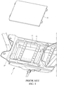
- An electric vehicle 1 is often provided with a receiving space 12 under a tread board 11 that is arranged for supporting user's feet to rest thereon. As shown in FIG 1 , the receiving space 12 receives and holds therein a battery 13 that supplies electrical power source to the electric vehicle 1. The battery 13 is received and stored in a battery box 14.
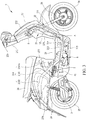
- TW533150 patent As shown in FIG. 2 , to make the battery 13 burglarproof, manufacturers have proposed an electric vehicle in TW533150 patent.
- the electric vehicle patent of TW533150 generally provides a tread board 11 having an end pivotally connected and an opposite end provided with a lock 15. Locking achieved with the lock 15 prevents the tread board 11 from being readily lifted open, so as to offer easy burglarproofness as being received and stored in the receiving space 12.
- the lock 15 since the lock 15 is arranged at an end of the tread board 11, the lock 15 may be easily contaminated as being treaded by a user and may also be stained by external dust. On the one hand, the lock 15 may be readily soiled and damaged and become hard to unlock and a user may get the soil attached in opening the lock 15, and on the other hand, the lock 15, being a simply structured lock that is exposed, may be of insufficiency in burglarproofness.
- the primary objective of the present invention is to provide a battery box locking structure of an electric vehicle, which helps overcome the drawbacks of inconvenience of locking operation and poor burglarproofness of a conventional battery box of an electric vehicle.
- the primary technical solution of the present invention as proposed in claim 1 is to provide a battery box locking structure of an electric vehicle, wherein the electric vehicle at least comprises a frame unit and a vehicle body cover unit that covers the frame unit; the frame unit comprises tread tubes and rear frames extending toward a rear side of a vehicle body, the tread tubes being arranged in a left and right pairwise form as a left tread tube and a right tread tube; the vehicle body cover unit at least comprises a tread board that shields the left tread tube and the right tread tube; a receiving space is defined under the tread board and receiving space receives therein a battery box, the battery box receiving and holding therein a battery that supplies electrical power to a driving motor that drives the electric vehicle, wherein the battery box has two sides that are provided with support shafts, and the battery box are shaft-supported on the left tread tube and the right tread tube by the support shafts in a vehicle body left-right direction, so that the battery box is rotatable about a rotation center defined by the support shafts in a vehicle
- the efficacy that the primary technical solution of the present invention proposed in claim 1 may achieve is that easiness of lifting and removal of a battery is improved and an effect of locking and positioning of a battery box is ensured so that burglarproofness of a battery is enhanced.
- the present invention provides a battery box locking structure of an electric vehicle.
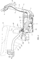
- a frame unit 21 of the electric vehicle 2 is provided, at a front side, with a head tube 22.
- the head tube 22 is provided, at an upper side thereof, with a steering mechanism 221.
- the steering mechanism 221 is connected, at a lower side thereof, to a front fork unit (front shock absorber) 23.
- the front fork unit 23 is provided, at a lower side thereof and in a rotatable manner, with a front wheel 24.
- the frame unit 21 is provided with a main tube 211 extending from the head tube 22 in a direction toward a rear side of a vehicle body.
- the main tube 211 is provided, as being further extended toward the rear side of the vehicle body, with tread tubes.
- the tread tubes are arranged pairwise in a left-right direction as a left tread tube 212 and a right tread tube 213.
- the left tread tube 212 and the right tread tube 213 are provided with rear frames 214 that are arranged pairwise in the left-right direction and extend toward the rear side of the vehicle body.
- the rear frames 214 comprise a rise section 2141 and a side frame section 2142.
- a transverse tube 2141a is arranged between the rise sections 2141.
- a rear wheel 25 is arranged rearward of and under the rear frames 214.
- a driving motor 3 is arranged at one side of the rear wheel 25 such that the driving motor 3 is operable to drive the rear wheel 25 in order to cause the electric vehicle 2 to more forward.
- a seat section 26 that is located above the rear wheel 25 is arranged rearward of the steering mechanism 221 such that a spacing distance is provided between the seat section 26 and the steering mechanism 221.
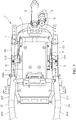
- the electric vehicle 2 is provided, on an outside thereof, with a vehicle body cover unit 27.
- the vehicle body cover unit 27 comprises a head cover 271 housing the steering mechanism 221, a front head cover 272 arranged at a lower side of the head cover 271 and housing a front end of the vehicle body, and a knee-shielding cover 273 arranged at a rear side of the front head cover 272.
- a tread board 274 is arranged between the steering mechanism 221 and the seat section 26 at a lower side thereof.
- a bottom cover 275 is arranged at a lower side of the tread board 274.
- the electric vehicle 2 is provided, on two sides thereof, with side vehicle body covers 276 at a lower side of the seat section 26.
- a central vehicle body cover 277 is provided in front of and at a lower side of the seat section 26.
- An article storage box 28 is provided at a lower side of the seat section 26 and an upper side of the article storage box 28 is shielded by the seat section 26.
- the electric vehicle 2 is provided with a power source, of which an example that is shown in the drawings includes a driving motor 3 driving the rear wheel 25.
- the electric vehicle 2 of the present invention can alternatively provided with a frontward-arranged motor that drives, by means of a chain or a belt, the rear wheel 25, or a driving mechanism that is made up of a motor and a transmission box to drive the rear wheel 25. It is noted here that the present invention is not limited to the specific way of driving the rear wheel 25 with the driving motor 3.
- the tread board 274 forms a foot support section 29, and the foot support section 29 functions to receive a rider's feet to place thereon.
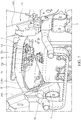
- the tread board 274, the bottom cover 275, and the left tread tube 212 and the right tread tube 213 define a receiving space A.
- the receiving space A receives therein a battery box 5, and the battery box 5 functions to receive and hold therein a battery 4.
- the battery 4 is electrically connected with the driving motor 3, in order to provide electrical power to the driving motor 3 to drive the rear wheel 25 to rotate.
- a control device (not shown in the drawings) provided on the steering mechanism 221 can be operated to activate the driving motor 3 to drive the rear wheel 25 to rotate so as to cause the electric vehicle 2 to move.
- the battery box 5 is received in the receiving space A defined by the tread board 274, the bottom cover 275, the left tread tube 212 and the right tread tube 213 in a manner of being arranged in a vehicle body front-rear direction of the electric vehicle 2.
- the left tread tube 212 is provided with a left shaft support section 2121
- the right tread tube 213 is provided with a right shaft support section 2131.
- the battery box 5 is provided, on two opposite sides thereof, with support shafts 51 projecting therefrom in a vehicle body left-right direction.
- the support shafts 51 that are arranged on the two sides of the battery box 5 are arranged above a battery box center axis 5a of the battery box 5 that extends in the vehicle body front-rear direction.
- the battery box 5 is shaft-supported by the support shafts 51 in the vehicle body left-right direction on the left shaft support section 2121 of the left tread tube 212 and the right shaft support section 2131 of the right tread tube 213.
- An upper surface of the battery box 5 is fixed to the tread board 274, and a lower surface of the battery box 5 is fixed to the bottom cover 275.
- One side of the battery box 5 is provided with an opening device 6.
- an electrical power source of the opening device 6 is supplied with a second battery 42 arranged at a lower side of a front portion of the article storage box 28.
- the steering mechanism 221 is provided with a control button (not shown in the drawings) that controls operation of the opening device 6.
- the control button can be operated to put the opening device 6 into operation for causing the battery box 5 to rotate, about a rotation center defined by the support shafts 51, toward the vehicle body front-rear direction, to an open position or a storage position in order to be opened in a condition of generally defining a right angle with respect to a ground surface, thereby allowing a user to withdraw and remove the battery 4 from the battery box 5.
- the opening device 6 can be arranged at the left side or the right side of the battery box 5, and in other words, the opening device 6 can be arranged on the left tread tube 212 or the right tread tube 213. Being arranged on the right tread tube 213 as shown in the instant embodiment is taken as an example for illustration; however, this invention is not limited to such an embodiment.
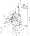
- the battery box 5 is provided on an external upper surface thereof with a positioning member 52 facing a rear side of the vehicle body.
- the positioning member 52 is arranged on the external upper surface of the battery box 5 and located closer to the rear side of the vehicle body than the support shafts 51 of the battery box 51.
- the positioning member 52 is embodied as a U-shaped buckle.
- the positioning member 52 is arranged in a manner of slightly inclining toward a frontward direction of the vehicle body.
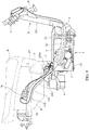
- a locking device 7 is provided on the transverse tube 2141a that is arranged between the rise sections 2141 of the frame unit 21.
- the locking device 7 is arranged on the transverse tube 2141a in a manner of slightly inclining in a direction toward the rearward direction of the vehicle body and the battery box 5. Further, as viewed from a lateral side, the locking device 7 is located between the article storage box 28 and the battery box 5.
- the locking device 7 comprises a positioning seat 71, a positioning hook 72 pivotally mounted on the positioning seat 71, a torsion spring 73 arranged at one side of the positioning hook 72 to provide the positioning hook 72 with a returning operation, and a constraint slide block 74 that is mounted on the positioning seat 71 and constrains the positioning hook 72 to locking engagement and locking release.
- the positioning seat 71 is mounted on the transverse tube 2141a in a manner of downward inclining so that the positioning hook 72 can be arranged in a manner of inclining toward the frontward direction of the vehicle body to allow the positioning hook 72 to smoothly hook on and lock to the positioning member 52 of the battery box 5.
- the constraint slide block 74 of the locking device 7 has an end that is provided with a connection section 741.
- the connection section 741 is connected to a control cable 75.
- An opposite end of the control cable 75 is connected to a main switch lock or a pull bar or a button of an operation unit 8 at one side of the head tube 22.
- a main switch lock is taken as an example of the operation unit 8 in the drawings for illustration.
- the operation unit 8 may drive the control cable 75 to move to cause the constraint slide block 75 to release a constrained condition of the positioning hook 72 so that the positioning hook 72 may be, under the action of a spring force of the torsion sprint 73, released from a hooking state.
- the control cable 75 may make the constraint slide block 74 release the constrained condition of the positioning hook 72 to thereby release the positioning hook 72 from the hooking state to achieve a mechanical control measure.
- the present invention further provides the control cable 75 connected to an electro-mechanical controller 76.
- the electro-mechanical controller 76 can be embodied as an electromagnetic valve in an example of reduction into practice.
- the electro-mechanical controller 76 is electrically connected through an electrical cable 761 to the operation unit 8 as a main switch lock or a bar or an electronic switch.
- a main switch lock is taken as an example of the operation unit 8 in the drawings for illustration.
- the operation unit 8 may control operation of the electro-mechanical controller 76 and the electro-mechanical controller 76 drives the control cable 75 to move, and the control cable 75 may make the constraint slide block 74 release the constrained condition of the positioning hook 72 to thereby release the positioning hook 72 from the hooking state to achieve a mechanical control measure.
- a user may operate the operation unit 8 to cause the locking device 7 to release the hooking state of the battery box 5.
- the battery box 5 may be moved by the opening device 6 (or turned manually) to cause the battery box 5 to rotate about a rotation center defined by the support shafts 51 toward the vehicle body front-rear direction to an open position, in order to be opened in a condition of generally defining a right angle with respect to a ground surface.
- a rear end (lower end) of the battery box 5 projects beyond a lower edge of the receiving space A in a direction toward the ground surface, so that the user may withdraw and remove the battery 4 from the battery box 5.
- the battery box 5 can be moved by the opening device 6 (or turned manually) to cause the battery box 5 to rotate about the rotation center defined by the support shafts 51 toward the vehicle body front-rear direction to a storage position.
- the positioning member 52 on the battery box 5 pushes an upper hook section 721 of the positioning hook 72 of the locking device 7 such that a lower hook section 722 of the positioning hook 72 hooks onto the positioning member 52 to form a locking and positioning condition of the battery box 5.
- lifting and removing the battery is made easy, and on the other hand, an effect of locking the battery box 5 is ensured to thereby improve burglarproofness of the battery 4.
- the battery box 5 further can be arranged, in a manner of being shaft-supported leftward and rightward, on the side frame sections 2142 of the left and right pairwise rear frames 214 of the frame unit 21.
- the battery box 5 is shaft-supported in the article storage box 28, so that a space of the electric vehicle 2 can be fully utilized and the battery 4 that is received in the battery box 5 is provided with feature of shielding.
- the head tube 22 of the frame unit 21 is provided, on a front side thereof, with a mounting frame 222.
- the mounting frame 222 allows the battery box 5 to arrange in a manner of being shaft-supported leftward and rightward, so that a space of the electric vehicle 2 can be fully utilized and the battery 4 that is received in the battery box 5 is provided with feature of shielding.
- the primary efficacy of the present invention is that a battery box 5 is provided with a positioning member 52 and a transverse tube 2141a of a frame unit 21 is provided with a locking device 7.
- the locking device comprises a positioning hook 72 and the positioning hook 72 is operable to apply an action of hooking and locking to the positioning member 52 so that an effect of locking and positioning is achieved for a battery box 5 that receives and holds a battery 4 in a stored condition to thereby improve the easiness of lifting and removal of the battery 4 and to ensure an effect of locking of the battery box 4 to thus improve burglarproofness of the battery 4.
- the second efficacy of the present invention is that a locking device 7 is mounted on a transverse tube 2141a of a frame unit 21 and a positioning member 52 is mounted on a battery box 5 so that easiness of arrangement of the locking device 7 and the positioning member 52 can be enhanced and a space of the electric vehicle 2 can be fully used.
- the third efficacy of the present invention is that rear frames 214 are provided with rise sections 2141 and side frame sections 2141 and a transverse tube 2141a is arranged on the rise sections 2141, the locking device being mounted on the transverse tube 2141a; a battery box 5 has a positioning member 52 that is provided on an external upper surface thereof at a location that is closer to a rear side of a vehicle body than support shafts 51 of the battery box 5 so that easiness of arrangement of the locking device 7 and the positioning member 52 can be enhanced and a space of the electric vehicle 2 can be fully used.
- the fourth efficacy of the present invention is that a locking device 7 is arranged on a transverse tube 2141a in a manner of slightly inclining in a direction toward a rear side of a vehicle body and a battery box 5 and a positioning member 52 is arranged on an external surface of the battery box 5 in a manner of slightly inclining toward a front side of the vehicle body so that an effect of locking between the locking device 7 and the positioning member 52 can be enhanced and a space of the electric vehicle 2 can be fully used.
- a locking device 7 comprises a positioning seat 71, a positioning hook 72 pivotally mounted on the positioning seat 71, a torsion spring 73 arranged at one side of the positioning hook 72 to cause the positioning hook 72 to take a position returning operation, and a constraint slide block 74 that is mounted on the positioning seat 71 and constrains the positioning hook 72 to locking engagement and locking release, the positioning member 52 being a U-shaped buckle so that an effect of locking between the locking device 7 and the positioning member 52 can be enhanced.
- the sixth efficacy of the present invention is that an article storage box 28 is mounted on a frame unit 21 and a locking device 7 is arranged between the article storage box 28 and a battery box 5 so that a space of the electric vehicle can be fully used.
- the seventh efficacy of the present invention is that a constraint slide block 7 has an end connected to a control cable 75 and the control cable 75 is connected to an operation unit 8, the operation unit 8 being a main switch lock or a pull bar or a button, so that operability of the locking device 7 can be enhanced.
- a constraint slide block 74 has an end connected to a control cable 75 and the control cable 75 is connected to an electro-mechanical controller 76, the electro-mechanical controller 76 being connected to an operation unit 8, the operation unit 8 being a main switch lock or a bar or en electronic switch, so that operability of the locking device 7 can be enhanced.
- the ninth efficacy of the present invention is that a central vehicle body cover 277 is arranged at a lower side of a front end of a seat section 26 and a battery box 5 is received and stored in a receiving space A defined by a left tread tube 212, a right tread tube 213, a tread board 274 and a bottom cover 275, such that at least a portion of a rear end of the battery box 5 is extended further toward a rear side of a vehicle body than the central vehicle body cover 277, so that a battery box 5, after being enlarged, interfering with other components can be avoided, thereby enhancing utilization of the battery box 5.
- the tenth efficacy of the present invention is that a tread board 274 is fixed to an upper surface of a battery box 5 and a bottom cover 275 is arranged on a lower surface of the battery box 5; the tread board 274 on the upper surface of the battery box 5 and the bottom cover 275 on the lower surface of the battery box 5 are openable in synchronization with the battery box 5 and thus, when the battery box 5 is opened in a condition of being generally at a right angle with respect to a ground surface, a rear end of the battery box 5 projects beyond a lower edge of a receiving space A in a direction toward the ground surface, so that withdrawal of a battery 4 from the battery box 5 by a user is made easy and at the same time, the battery box 5, after being enlarged, interfering with other components can be avoided, thereby enhancing utilization of the battery box 5.
- the eleventh efficacy of the present invention is that an article storage box 28 is provided on side frame sections 2142 of a frame unit 21 and a battery box 5 is shaft-supported on the side frame sections 2142 of the frame unit 21 in a manner of being shaft-supported in a vehicle body left-right direction, and is received in the article storage box 28, so that a space of an electric vehicle 2 can be fully used and a battery 4 received in the battery box 5 is provided with a feature of shielding.
- the twelfth efficacy of the present invention is that a head tube 22 of a frame unit 21 is provided with a mounting frame 222 and a battery box 5 is shaft-supported on the mounting frame 222, in a manner of being shaft-supported in a vehicle body left-right direction, so that a space of an electric vehicle 2 can be fully used and a battery 4 received in the battery box 5 is provided with a feature of shielding.
- the thirteenth efficacy of the present invention is that an electro-mechanical controller 75 is provided as an electromagnetic valve and an operation unit 8 controls operation of the electromagnetic valve so that the electromagnetic valve drives a control cable 75 and the control cable 75 is caused to make a constraint slide block 74 to release a constrained condition of a positioning hook 72 to allow the positioning hook 72 to release a hooking state, so that operability of a locking device 7 is enhanced.
Abstract
Description
- The present invention generally relates to a battery box locking structure of an electric vehicle, and more particularly to a battery box locking structure of an electric vehicle that improves easiness of locking operation and burglarproofness of a battery box.
- An
electric vehicle 1 is often provided with areceiving space 12 under atread board 11 that is arranged for supporting user's feet to rest thereon. As shown inFIG 1 , thereceiving space 12 receives and holds therein abattery 13 that supplies electrical power source to theelectric vehicle 1. Thebattery 13 is received and stored in abattery box 14. - As shown in
FIG. 2 , to make thebattery 13 burglarproof, manufacturers have proposed an electric vehicle inTW533150 TW533150 tread board 11 having an end pivotally connected and an opposite end provided with alock 15. Locking achieved with thelock 15 prevents thetread board 11 from being readily lifted open, so as to offer easy burglarproofness as being received and stored in thereceiving space 12. - Although storage of the
battery 13 as provided in the above knownelectric vehicle 1 provides thebattery 13 with easiness of storage and easy burglarproofness, since thelock 15 is arranged at an end of thetread board 11, thelock 15 may be easily contaminated as being treaded by a user and may also be stained by external dust. On the one hand, thelock 15 may be readily soiled and damaged and become hard to unlock and a user may get the soil attached in opening thelock 15, and on the other hand, thelock 15, being a simply structured lock that is exposed, may be of insufficiency in burglarproofness. - Thus, it is a challenge of the electric vehicle industry to provide a battery box locking structure of an electric vehicle that helps improve withdrawal and burglarproofness of a battery of an electric vehicle.
- The primary objective of the present invention is to provide a battery box locking structure of an electric vehicle, which helps overcome the drawbacks of inconvenience of locking operation and poor burglarproofness of a conventional battery box of an electric vehicle.
- For such a purpose, the primary technical solution of the present invention as proposed in
claim 1 is to provide a battery box locking structure of an electric vehicle, wherein the electric vehicle at least comprises a frame unit and a vehicle body cover unit that covers the frame unit; the frame unit comprises tread tubes and rear frames extending toward a rear side of a vehicle body, the tread tubes being arranged in a left and right pairwise form as a left tread tube and a right tread tube; the vehicle body cover unit at least comprises a tread board that shields the left tread tube and the right tread tube; a receiving space is defined under the tread board and receiving space receives therein a battery box, the battery box receiving and holding therein a battery that supplies electrical power to a driving motor that drives the electric vehicle, wherein the battery box has two sides that are provided with support shafts, and the battery box are shaft-supported on the left tread tube and the right tread tube by the support shafts in a vehicle body left-right direction, so that the battery box is rotatable about a rotation center defined by the support shafts in a vehicle body front-rear direction to an open position or a storage position; a locking device is mounted to the frame unit and the locking device is connected to a control cable, the control cable being connected to an operation unit; a positioning member is provided on an outside of the battery box and the locking device is operable to hook and lock the positioning member so that the operation unit is operable to cause the locking device to hook and lock the positioning member or to release the positioning member from being hooked and locked. - The efficacy that the primary technical solution of the present invention proposed in
claim 1 may achieve is that easiness of lifting and removal of a battery is improved and an effect of locking and positioning of a battery box is ensured so that burglarproofness of a battery is enhanced. -
-
FIG. 1 is a schematic view illustrating a conventional electric vehicle battery box. -
FIG. 2 illustrates the prior art patent document ofTW533150 -
FIG. 3 is a side elevational view illustrating an electric vehicle according to the present invention. -
FIG. 4 is a schematic view illustrating an arrangement of a battery box of the electric vehicle according to the present invention. -
FIG. 5 is a top plan view illustrating the arrangement of the battery box of the electric vehicle according to the present invention. -
FIG. 6 is a side elevational view, in a schematic form, illustrating the battery box of the electric vehicle according to the present invention. -
FIG. 7 is a rear view, in a schematic form, illustrating a positioning member and a locking device of the battery box according to the present invention. -
FIG. 8 is a perspective view illustrating the locking device according to the present invention. -
FIG. 9 is a side elevational view, in a schematic form, illustrating the positioning member and the locking device of the battery box according to the present invention. -
FIGS. 10 and11 are schematic views illustrating a locking operation of the positioning member and the locking device of the battery box according to the present invention. -
FIG. 12 is a schematic view illustrating opening of the battery box the electric vehicle according to the present invention. -
FIG. 13 shows another embodiment of the arrangement of the battery box of the electric vehicle according to the present invention. -
FIG. 14 shows a further embodiment of the arrangement of the battery box of the electric vehicle according to the present invention. - Firstly, referring to
FIGS. 3 ,4 , and5 , the present invention provides a battery box locking structure of an electric vehicle. Aframe unit 21 of theelectric vehicle 2 is provided, at a front side, with ahead tube 22. Thehead tube 22 is provided, at an upper side thereof, with asteering mechanism 221. Thesteering mechanism 221 is connected, at a lower side thereof, to a front fork unit (front shock absorber) 23. Thefront fork unit 23 is provided, at a lower side thereof and in a rotatable manner, with afront wheel 24. Theframe unit 21 is provided with amain tube 211 extending from thehead tube 22 in a direction toward a rear side of a vehicle body. Themain tube 211 is provided, as being further extended toward the rear side of the vehicle body, with tread tubes. The tread tubes are arranged pairwise in a left-right direction as aleft tread tube 212 and aright tread tube 213. Theleft tread tube 212 and theright tread tube 213 are provided withrear frames 214 that are arranged pairwise in the left-right direction and extend toward the rear side of the vehicle body. Therear frames 214 comprise arise section 2141 and aside frame section 2142. Atransverse tube 2141a is arranged between therise sections 2141. Arear wheel 25 is arranged rearward of and under therear frames 214. A drivingmotor 3 is arranged at one side of therear wheel 25 such that the drivingmotor 3 is operable to drive therear wheel 25 in order to cause theelectric vehicle 2 to more forward. Aseat section 26 that is located above therear wheel 25 is arranged rearward of thesteering mechanism 221 such that a spacing distance is provided between theseat section 26 and thesteering mechanism 221. Theelectric vehicle 2 is provided, on an outside thereof, with a vehiclebody cover unit 27. The vehiclebody cover unit 27 comprises ahead cover 271 housing thesteering mechanism 221, afront head cover 272 arranged at a lower side of thehead cover 271 and housing a front end of the vehicle body, and a knee-shielding cover 273 arranged at a rear side of thefront head cover 272. Atread board 274 is arranged between thesteering mechanism 221 and theseat section 26 at a lower side thereof. Abottom cover 275 is arranged at a lower side of thetread board 274. Theelectric vehicle 2 is provided, on two sides thereof, with side vehicle body covers 276 at a lower side of theseat section 26. A centralvehicle body cover 277 is provided in front of and at a lower side of theseat section 26. Anarticle storage box 28 is provided at a lower side of theseat section 26 and an upper side of thearticle storage box 28 is shielded by theseat section 26. Theelectric vehicle 2 is provided with a power source, of which an example that is shown in the drawings includes a drivingmotor 3 driving therear wheel 25. In practice, theelectric vehicle 2 of the present invention can alternatively provided with a frontward-arranged motor that drives, by means of a chain or a belt, therear wheel 25, or a driving mechanism that is made up of a motor and a transmission box to drive therear wheel 25. It is noted here that the present invention is not limited to the specific way of driving therear wheel 25 with thedriving motor 3. - As shown in
FIGS. 3 ,4 , and5 , thetread board 274 forms afoot support section 29, and thefoot support section 29 functions to receive a rider's feet to place thereon. Thetread board 274, thebottom cover 275, and theleft tread tube 212 and theright tread tube 213 define a receiving space A. The receiving space A receives therein abattery box 5, and thebattery box 5 functions to receive and hold therein abattery 4. Thebattery 4 is electrically connected with thedriving motor 3, in order to provide electrical power to the drivingmotor 3 to drive therear wheel 25 to rotate. As such, a control device (not shown in the drawings) provided on thesteering mechanism 221 can be operated to activate the drivingmotor 3 to drive therear wheel 25 to rotate so as to cause theelectric vehicle 2 to move. - As shown in
FIGS. 3 ,4 ,5 , and6 , thebattery box 5 is received in the receiving space A defined by thetread board 274, thebottom cover 275, theleft tread tube 212 and theright tread tube 213 in a manner of being arranged in a vehicle body front-rear direction of theelectric vehicle 2. Theleft tread tube 212 is provided with a leftshaft support section 2121, and theright tread tube 213 is provided with a rightshaft support section 2131. Speaking more specifically, thebattery box 5 is provided, on two opposite sides thereof, withsupport shafts 51 projecting therefrom in a vehicle body left-right direction. Thesupport shafts 51 that are arranged on the two sides of thebattery box 5 are arranged above a batterybox center axis 5a of thebattery box 5 that extends in the vehicle body front-rear direction. As such, thebattery box 5 is shaft-supported by thesupport shafts 51 in the vehicle body left-right direction on the leftshaft support section 2121 of theleft tread tube 212 and the rightshaft support section 2131 of theright tread tube 213. An upper surface of thebattery box 5 is fixed to thetread board 274, and a lower surface of thebattery box 5 is fixed to thebottom cover 275. One side of thebattery box 5 is provided with anopening device 6. - As shown in
FIGS. 3 ,4 ,5 , and6 , an electrical power source of theopening device 6 is supplied with a second battery 42 arranged at a lower side of a front portion of thearticle storage box 28. Further, thesteering mechanism 221 is provided with a control button (not shown in the drawings) that controls operation of theopening device 6. As such, the control button can be operated to put theopening device 6 into operation for causing thebattery box 5 to rotate, about a rotation center defined by thesupport shafts 51, toward the vehicle body front-rear direction, to an open position or a storage position in order to be opened in a condition of generally defining a right angle with respect to a ground surface, thereby allowing a user to withdraw and remove thebattery 4 from thebattery box 5. Theopening device 6 can be arranged at the left side or the right side of thebattery box 5, and in other words, theopening device 6 can be arranged on theleft tread tube 212 or theright tread tube 213. Being arranged on theright tread tube 213 as shown in the instant embodiment is taken as an example for illustration; however, this invention is not limited to such an embodiment. - As shown in
FIGS. 4 ,6 ,7 , and8 , thebattery box 5 is provided on an external upper surface thereof with a positioningmember 52 facing a rear side of the vehicle body. The positioningmember 52 is arranged on the external upper surface of thebattery box 5 and located closer to the rear side of the vehicle body than thesupport shafts 51 of thebattery box 51. The positioningmember 52 is embodied as a U-shaped buckle. The positioningmember 52 is arranged in a manner of slightly inclining toward a frontward direction of the vehicle body. Alocking device 7 is provided on thetransverse tube 2141a that is arranged between therise sections 2141 of theframe unit 21. Thelocking device 7 is arranged on thetransverse tube 2141a in a manner of slightly inclining in a direction toward the rearward direction of the vehicle body and thebattery box 5. Further, as viewed from a lateral side, thelocking device 7 is located between thearticle storage box 28 and thebattery box 5. Thelocking device 7 comprises apositioning seat 71, apositioning hook 72 pivotally mounted on thepositioning seat 71, atorsion spring 73 arranged at one side of thepositioning hook 72 to provide thepositioning hook 72 with a returning operation, and aconstraint slide block 74 that is mounted on thepositioning seat 71 and constrains thepositioning hook 72 to locking engagement and locking release. As viewed in a lateral side, the positioningseat 71 is mounted on thetransverse tube 2141a in a manner of downward inclining so that thepositioning hook 72 can be arranged in a manner of inclining toward the frontward direction of the vehicle body to allow thepositioning hook 72 to smoothly hook on and lock to the positioningmember 52 of thebattery box 5. Theconstraint slide block 74 of thelocking device 7 has an end that is provided with aconnection section 741. Theconnection section 741 is connected to acontrol cable 75. An opposite end of thecontrol cable 75 is connected to a main switch lock or a pull bar or a button of anoperation unit 8 at one side of thehead tube 22. A main switch lock is taken as an example of theoperation unit 8 in the drawings for illustration. As such, theoperation unit 8 may drive thecontrol cable 75 to move to cause theconstraint slide block 75 to release a constrained condition of thepositioning hook 72 so that thepositioning hook 72 may be, under the action of a spring force of thetorsion sprint 73, released from a hooking state. With the above-describedoperation unit 8 driving thecontrol cable 75 to move, thecontrol cable 75 may make theconstraint slide block 74 release the constrained condition of thepositioning hook 72 to thereby release thepositioning hook 72 from the hooking state to achieve a mechanical control measure. - As shown in
FIG. 9 , the present invention further provides thecontrol cable 75 connected to an electro-mechanical controller 76. The electro-mechanical controller 76 can be embodied as an electromagnetic valve in an example of reduction into practice. The electro-mechanical controller 76 is electrically connected through anelectrical cable 761 to theoperation unit 8 as a main switch lock or a bar or an electronic switch. A main switch lock is taken as an example of theoperation unit 8 in the drawings for illustration. As such, theoperation unit 8 may control operation of the electro-mechanical controller 76 and the electro-mechanical controller 76 drives thecontrol cable 75 to move, and thecontrol cable 75 may make theconstraint slide block 74 release the constrained condition of thepositioning hook 72 to thereby release thepositioning hook 72 from the hooking state to achieve a mechanical control measure. - As shown in
FIGS. 4 ,7 ,10 ,11 , and12 , to lift and remove thebattery 4 that is received and stored in thebattery box 5 for maintenance or charging, a user may operate theoperation unit 8 to cause thelocking device 7 to release the hooking state of thebattery box 5. Under this condition, thebattery box 5 may be moved by the opening device 6 (or turned manually) to cause thebattery box 5 to rotate about a rotation center defined by thesupport shafts 51 toward the vehicle body front-rear direction to an open position, in order to be opened in a condition of generally defining a right angle with respect to a ground surface. Under this condition, a rear end (lower end) of thebattery box 5 projects beyond a lower edge of the receiving space A in a direction toward the ground surface, so that the user may withdraw and remove thebattery 4 from thebattery box 5. When thebattery 4 is put into and stored in thebattery box 5 again and thebattery box 5 is once again received in the receiving space A of thetread section 29, thebattery box 5 can be moved by the opening device 6 (or turned manually) to cause thebattery box 5 to rotate about the rotation center defined by thesupport shafts 51 toward the vehicle body front-rear direction to a storage position. Under this condition, the positioningmember 52 on thebattery box 5 pushes anupper hook section 721 of thepositioning hook 72 of thelocking device 7 such that alower hook section 722 of thepositioning hook 72 hooks onto the positioningmember 52 to form a locking and positioning condition of thebattery box 5. As such, on the one hand, lifting and removing the battery is made easy, and on the other hand, an effect of locking thebattery box 5 is ensured to thereby improve burglarproofness of thebattery 4. - As shown in
FIG. 13 , in putting the present invention into practice, thebattery box 5 further can be arranged, in a manner of being shaft-supported leftward and rightward, on theside frame sections 2142 of the left and right pairwise rear frames 214 of theframe unit 21. Speaking more precisely, thebattery box 5 is shaft-supported in thearticle storage box 28, so that a space of theelectric vehicle 2 can be fully utilized and thebattery 4 that is received in thebattery box 5 is provided with feature of shielding. - As shown in
FIG. 14 , in putting the present invention into practice, thehead tube 22 of theframe unit 21 is provided, on a front side thereof, with a mountingframe 222. The mountingframe 222 allows thebattery box 5 to arrange in a manner of being shaft-supported leftward and rightward, so that a space of theelectric vehicle 2 can be fully utilized and thebattery 4 that is received in thebattery box 5 is provided with feature of shielding. - The primary efficacy of the present invention is that a
battery box 5 is provided with a positioningmember 52 and atransverse tube 2141a of aframe unit 21 is provided with alocking device 7. The locking device comprises apositioning hook 72 and thepositioning hook 72 is operable to apply an action of hooking and locking to the positioningmember 52 so that an effect of locking and positioning is achieved for abattery box 5 that receives and holds abattery 4 in a stored condition to thereby improve the easiness of lifting and removal of thebattery 4 and to ensure an effect of locking of thebattery box 4 to thus improve burglarproofness of thebattery 4. - The second efficacy of the present invention is that a
locking device 7 is mounted on atransverse tube 2141a of aframe unit 21 and a positioningmember 52 is mounted on abattery box 5 so that easiness of arrangement of thelocking device 7 and the positioningmember 52 can be enhanced and a space of theelectric vehicle 2 can be fully used. - The third efficacy of the present invention is that
rear frames 214 are provided withrise sections 2141 andside frame sections 2141 and atransverse tube 2141a is arranged on therise sections 2141, the locking device being mounted on thetransverse tube 2141a; abattery box 5 has a positioningmember 52 that is provided on an external upper surface thereof at a location that is closer to a rear side of a vehicle body thansupport shafts 51 of thebattery box 5 so that easiness of arrangement of thelocking device 7 and the positioningmember 52 can be enhanced and a space of theelectric vehicle 2 can be fully used. - The fourth efficacy of the present invention is that a
locking device 7 is arranged on atransverse tube 2141a in a manner of slightly inclining in a direction toward a rear side of a vehicle body and abattery box 5 and a positioningmember 52 is arranged on an external surface of thebattery box 5 in a manner of slightly inclining toward a front side of the vehicle body so that an effect of locking between the lockingdevice 7 and the positioningmember 52 can be enhanced and a space of theelectric vehicle 2 can be fully used. - The fifth efficacy of the present invention is that a
locking device 7 comprises apositioning seat 71, apositioning hook 72 pivotally mounted on thepositioning seat 71, atorsion spring 73 arranged at one side of thepositioning hook 72 to cause thepositioning hook 72 to take a position returning operation, and aconstraint slide block 74 that is mounted on thepositioning seat 71 and constrains thepositioning hook 72 to locking engagement and locking release, the positioningmember 52 being a U-shaped buckle so that an effect of locking between the lockingdevice 7 and the positioningmember 52 can be enhanced. - The sixth efficacy of the present invention is that an
article storage box 28 is mounted on aframe unit 21 and alocking device 7 is arranged between thearticle storage box 28 and abattery box 5 so that a space of the electric vehicle can be fully used. - The seventh efficacy of the present invention is that a
constraint slide block 7 has an end connected to acontrol cable 75 and thecontrol cable 75 is connected to anoperation unit 8, theoperation unit 8 being a main switch lock or a pull bar or a button, so that operability of thelocking device 7 can be enhanced. - The eighth efficacy of the present invention is that a
constraint slide block 74 has an end connected to acontrol cable 75 and thecontrol cable 75 is connected to an electro-mechanical controller 76, the electro-mechanical controller 76 being connected to anoperation unit 8, theoperation unit 8 being a main switch lock or a bar or en electronic switch, so that operability of thelocking device 7 can be enhanced. - The ninth efficacy of the present invention is that a central
vehicle body cover 277 is arranged at a lower side of a front end of aseat section 26 and abattery box 5 is received and stored in a receiving space A defined by aleft tread tube 212, aright tread tube 213, atread board 274 and abottom cover 275, such that at least a portion of a rear end of thebattery box 5 is extended further toward a rear side of a vehicle body than the centralvehicle body cover 277, so that abattery box 5, after being enlarged, interfering with other components can be avoided, thereby enhancing utilization of thebattery box 5. - The tenth efficacy of the present invention is that a
tread board 274 is fixed to an upper surface of abattery box 5 and abottom cover 275 is arranged on a lower surface of thebattery box 5; thetread board 274 on the upper surface of thebattery box 5 and thebottom cover 275 on the lower surface of thebattery box 5 are openable in synchronization with thebattery box 5 and thus, when thebattery box 5 is opened in a condition of being generally at a right angle with respect to a ground surface, a rear end of thebattery box 5 projects beyond a lower edge of a receiving space A in a direction toward the ground surface, so that withdrawal of abattery 4 from thebattery box 5 by a user is made easy and at the same time, thebattery box 5, after being enlarged, interfering with other components can be avoided, thereby enhancing utilization of thebattery box 5. - The eleventh efficacy of the present invention is that an
article storage box 28 is provided onside frame sections 2142 of aframe unit 21 and abattery box 5 is shaft-supported on theside frame sections 2142 of theframe unit 21 in a manner of being shaft-supported in a vehicle body left-right direction, and is received in thearticle storage box 28, so that a space of anelectric vehicle 2 can be fully used and abattery 4 received in thebattery box 5 is provided with a feature of shielding. - The twelfth efficacy of the present invention is that a
head tube 22 of aframe unit 21 is provided with a mountingframe 222 and abattery box 5 is shaft-supported on the mountingframe 222, in a manner of being shaft-supported in a vehicle body left-right direction, so that a space of anelectric vehicle 2 can be fully used and abattery 4 received in thebattery box 5 is provided with a feature of shielding. - The thirteenth efficacy of the present invention is that an electro-
mechanical controller 75 is provided as an electromagnetic valve and anoperation unit 8 controls operation of the electromagnetic valve so that the electromagnetic valve drives acontrol cable 75 and thecontrol cable 75 is caused to make aconstraint slide block 74 to release a constrained condition of apositioning hook 72 to allow thepositioning hook 72 to release a hooking state, so that operability of alocking device 7 is enhanced.
Claims (13)
- A battery box locking structure of an electric vehicle, wherein the electric vehicle (2) at least comprises a frame unit (21) and a vehicle body cover unit (27) that covers the frame unit (21); the frame unit (21) comprises tread tubes (212, 213) and rear frames (214) extending toward a rear side of a vehicle body, the tread tubes (212, 213) being arranged in a left and right pairwise form as a left tread tube (212) and a right tread tube (213); the vehicle body cover unit (27) at least comprises a tread board (274) that shields the left tread tube (212) and the right tread tube (213); a receiving space (A) is defined under the tread board (274) and receiving space (A) receives therein a battery box (5), the battery box (5) receiving and holding therein a battery (4) that supplies electrical power to a driving motor (3) that drives the electric vehicle (2), characterized in that the battery box (5) has two sides that are provided with support shafts (51), and the battery box (5) are shaft-supported on the left tread tube (212) and the right tread tube (213) by the support shafts (51) in a vehicle body left-right direction, so that the battery box (5) is rotatable about a rotation center defined by the support shafts (51) in a vehicle body front-rear direction to an open position or a storage position; a locking device (7) is mounted to the frame unit (21) and the locking device (7) is connected to a control cable (75), the control cable (75) being connected to an operation unit (8); a positioning member (52) is provided on an outside of the battery box (5) and the locking device (7) is operable to hook and lock the positioning member (52) so that the operation unit (8) is operable to cause the locking device (7) to hook and lock the positioning member (52) or to release the positioning member (52) from being hooked and locked.
- A battery box locking structure of an electric vehicle, wherein the electric vehicle (2) at least comprises a frame unit (21) and a vehicle body cover unit (27) that covers the frame unit (21); the frame unit (21) comprises tread tubes (212, 213) and rear frames (214) extending toward a rear side of a vehicle body, the tread tubes (212, 213) being arranged in a left and right pairwise form as a left tread tube (212) and a right tread tube (213); the vehicle body cover unit (27) at least comprises a tread board (274) that shields the left tread tube (212) and the right tread tube (213); a receiving space (A) is defined under the tread board (274) and receiving space (A) receives therein a battery box (5), the battery box (5) receiving and holding therein a battery (4) that supplies electrical power to a driving motor (3) that drives the electric vehicle (2), characterized in that the battery box (5) has two sides that are provided with support shafts (51), and the battery box (5) are shaft-supported on the left tread tube (212) and the right tread tube (213) by the support shafts (51) in a vehicle body left-right direction, so that the battery box (5) is rotatable about a rotation center defined by the support shafts (51) in a vehicle body front-rear direction to an open position or a storage position; the frame unit (21) comprises a transverse tube (2141a) and a locking device (7) is mounted to the transverse tube (2141a), a positioning member (52) being provided on an outside of the battery box (5); the locking device (7) is connected to a control cable (75), the control cable (75) being connected to an operation unit (8); the locking device (7) is operable to hook and lock the positioning member (52) so that the operation unit (8) is operable to cause the locking device (7) to hook and lock the positioning member (52) or to release the positioning member (52) from being hooked and locked.
- The battery box locking structure of the electric vehicle according to claim 1, wherein the rear frames (214) comprise rise sections (2141) and side frame sections (2142), a transverse tube (2141a) being arranged on the rise sections (2141), the locking device (7) being mounted to the transverse tube (2141a); and the positioning member (52) is provided on an external upper surface of the battery box (5) at a location closer to the rear side of the vehicle body than the support shafts (51) of the battery box (5).
- The battery box locking structure of the electric vehicle according to claim 3, wherein the locking device (7) is arranged on the transverse tube (2141a) in a manner of slightly inclining in a direction toward the rear side of the vehicle body and the battery box (5) and the positioning member (52) is arranged on the external surface of the battery box (5) in a manner of slightly inclining toward a front side of the vehicle body.
- The battery box locking structure of the electric vehicle according to claim 1, 2, 3, or 4, wherein the locking device (7) comprises a positioning seat (71), a positioning hook (72) pivotally mounted on the positioning seat (71), a torsion spring (73) arranged at one side of the positioning hook (72) to cause the positioning hook (72) to take a position returning operation, and a constraint slide block (74) that is mounted on the positioning seat (71) and constrains the positioning hook (72) to locking engagement and locking release, the positioning member (52) being a U-shaped buckle.
- The battery box locking structure of the electric vehicle according to claim 1 or 2, wherein an article storage box (28) is mounted on the frame unit (21) and the locking device (7) s arranged between the article storage box (28) and the battery box (5).
- The battery box locking structure of the electric vehicle according to claim 5, wherein the constraint slide block (74) has an end connected to the control cable (75) and the control cable (75) is connected to the operation unit (8), the operation unit (8) being a main switch lock or a pull bar or a button.
- The battery box locking structure of the electric vehicle according to claim 5, wherein the constraint slide block (74) has an end connected to the control cable (75), the control cable (75) being connected to an electro-mechanical controller (76), the electro-mechanical controller (76) being connected to the operation unit (8), the operation unit (8) being a main switch lock or a bar or an electronic switch.
- The battery box locking structure of the electric vehicle according to claim 1 or 2, wherein the frame unit (21) comprises a seat section (26), and the vehicle body cover unit (27) comprises a central vehicle body cover (277); the central vehicle body cover (277) is arranged at a lower side of a front end of the seat section (26), the battery box (5) being received in the receiving space (A) defined by the left tread tube (212), the right tread tube (213), the tread board (274) and a bottom cover (275), at least a portion of a rear end of the battery box (5) extending further toward the rear side of the vehicle body than the central vehicle body cover (277).
- The battery box locking structure of the electric vehicle according to claim 1 or 2, wherein a bottom cover (275) is arranged below of the tread board (274); the tread board (274) is fixed to an upper surface of the battery box (5) and the bottom cover (275) is fixed to a lower surface of the battery box (5); the tread board (274) on the upper surface of the battery box (5) and the bottom cover (275) on the lower surface of the battery box (5) are openable in synchronization with the battery box (5), so that when the battery box (5) is opened to a condition of being generally at a right angle with respect to a ground surface, a rear end of the battery box (5) projects beyond a lower edge of the receiving space (A) in a direction toward the ground surface.
- The battery box locking structure of the electric vehicle according to claim 1 or 2, wherein the frame unit (21) comprises side frame sections (2142) arranged in a left and right pairwise form, an article storage box (28) being provided on the side frame sections (2142) of the frame unit (21), the battery box (5) being shaft-supported on the side frame sections (2142) of the frame unit (21) in a manner of being shaft-supported in the vehicle body left-right direction, and is received in the article storage box (28).
- The battery box locking structure of the electric vehicle according to claim 1 or 2, wherein the frame unit (21) further comprises a head tube (22), the head tube (22) of the frame unit (21) being provided with a mounting frame (222), the battery box (5) being shaft-supported on the mounting frame (222) in a manner of being shaft-supported in the vehicle body left-right direction.
- The battery box locking structure of the electric vehicle according to claim 8, wherein the electro-mechanical controller (76) comprises an electromagnetic valve; the operation unit (8) controls operation of the electromagnetic valve, the electromagnetic valve driving the control cable (75), the control cable (75) causing the constraint slide block (74) to release a constrained condition of the positioning hook (72) to allow the positioning hook (72) to release a hooking state.
Applications Claiming Priority (1)
| Application Number | Priority Date | Filing Date | Title |
|---|---|---|---|
| TW107103527A TWI663089B (en) | 2018-01-31 | 2018-01-31 | Battery box locking device for electric vehicle |
Publications (2)
| Publication Number | Publication Date |
|---|---|
| EP3521082A1 true EP3521082A1 (en) | 2019-08-07 |
| EP3521082A8 EP3521082A8 (en) | 2020-02-26 |
Family
ID=65030934
Family Applications (1)
| Application Number | Title | Priority Date | Filing Date |
|---|---|---|---|
| EP19151741.6A Withdrawn EP3521082A1 (en) | 2018-01-31 | 2019-01-15 | Battery box locking structure of electric vehicle |
Country Status (6)
| Country | Link |
|---|---|
| US (1) | US10351017B1 (en) |
| EP (1) | EP3521082A1 (en) |
| JP (1) | JP6777770B2 (en) |
| CN (1) | CN110091956B (en) |
| CA (1) | CA3030034A1 (en) |
| TW (1) | TWI663089B (en) |
Families Citing this family (7)
| Publication number | Priority date | Publication date | Assignee | Title |
|---|---|---|---|---|
| JP6670814B2 (en) * | 2017-11-21 | 2020-03-25 | 本田技研工業株式会社 | Saddle type vehicle |
| DE102018123252A1 (en) * | 2018-09-21 | 2020-03-26 | Share your BICAR AG | COMPACT THREE-WHEEL ELECTRIC VEHICLE |
| US11370319B2 (en) * | 2019-06-21 | 2022-06-28 | Acton, Inc. | Electric scooter with top-swappable battery |
| CN110690385A (en) * | 2019-11-06 | 2020-01-14 | 天津富士达自行车工业有限公司 | Fixing structure of electric bicycle frame tube downward-placing type battery pack |
| TWI738425B (en) * | 2020-07-20 | 2021-09-01 | 英屬開曼群島商睿能創意公司 | Battery fixing structure and carrier including battery fixing structure |
| CN114039159A (en) * | 2020-07-20 | 2022-02-11 | 睿能创意公司 | Battery fixing structure and carrier |
| CN114122604A (en) * | 2021-11-29 | 2022-03-01 | 金鸿松 | Electric automobile battery safety anti-theft device convenient to change battery package |
Citations (6)
| Publication number | Priority date | Publication date | Assignee | Title |
|---|---|---|---|---|
| JPH0872558A (en) * | 1994-07-01 | 1996-03-19 | Tokyo R & D:Kk | Method and device for exchanging mounting battery between motorcars |
| EP0741060A2 (en) * | 1995-05-01 | 1996-11-06 | Yamaha Hatsudoki Kabushiki Kaisha | Battery powered motor scooter and battery exchange device |
| TW533150B (en) | 1999-03-01 | 2003-05-21 | Tokyo R & D Kk | Electric vehicle |
| EP2623404A1 (en) * | 2010-09-30 | 2013-08-07 | Suzuki Motor Corporation | Electric two-wheeled vehicle |
| CN102874083B (en) * | 2011-07-12 | 2016-08-31 | 光阳工业股份有限公司 | The battery assembling device of battery-operated motor cycle |
| WO2016156895A1 (en) * | 2015-03-31 | 2016-10-06 | Honda Motor Company Limited | Headlight mounting structure for a motorcycle |
Family Cites Families (28)
| Publication number | Priority date | Publication date | Assignee | Title |
|---|---|---|---|---|
| JPH06278667A (en) * | 1993-01-26 | 1994-10-04 | Honda Motor Co Ltd | Electric vehicle |
| JP3412701B2 (en) * | 1993-10-19 | 2003-06-03 | 本田技研工業株式会社 | Cover structure and battery storage case structure for electric vehicles |
| JP3231551B2 (en) * | 1994-06-11 | 2001-11-26 | 本田技研工業株式会社 | Battery detachable structure for electric assist bicycle |
| JP3420349B2 (en) * | 1994-09-07 | 2003-06-23 | セイコーエプソン株式会社 | Electric power unit and power transmission unit for electric vehicle |
| JPH08276880A (en) * | 1995-04-05 | 1996-10-22 | Tokyo R & D:Kk | Motor-driven bicycle |
| JPH09216588A (en) * | 1996-02-13 | 1997-08-19 | Suzuki Motor Corp | Battery installing structure of electric bicycle |
| TW463402B (en) * | 1999-03-12 | 2001-11-11 | Toshiba Battery | Battery pack and power tool |
| US7469760B2 (en) * | 2000-03-02 | 2008-12-30 | Deka Products Limited Partnership | Hybrid electric vehicles using a stirling engine |
| JP2001354179A (en) * | 2000-06-14 | 2001-12-25 | Honda Motor Co Ltd | Fuel cell-mounted motorcycle |
| US6568496B1 (en) * | 2001-11-20 | 2003-05-27 | Yung Ho Huang | Electromotive motorcycle arranged with power system using fuel cell |
| US7249644B2 (en) * | 2003-05-30 | 2007-07-31 | Honda Motor Co., Ltd. | Electric vehicle |
| US6814172B1 (en) * | 2003-07-21 | 2004-11-09 | Oanh Ngoc Vu | Electric power unit for two-wheel vehicles |
| JP5167055B2 (en) * | 2008-09-30 | 2013-03-21 | 本田技研工業株式会社 | Electric motorcycle |
| US8376075B2 (en) * | 2008-09-30 | 2013-02-19 | Honda Motor Co., Ltd. | Saddle-ride electric vehicle |
| JP5253951B2 (en) * | 2008-09-30 | 2013-07-31 | 本田技研工業株式会社 | Straddle-type electric vehicle |
| JP4908490B2 (en) * | 2008-12-26 | 2012-04-04 | 本田技研工業株式会社 | Battery storage box structure for saddle riding type electric vehicle |
| EP2412622B1 (en) * | 2009-03-27 | 2013-09-11 | Honda Motor Co., Ltd. | Electric straddled vehicle |
| CN201647053U (en) * | 2009-11-24 | 2010-11-24 | 谢庆生 | Electric bicycle in form with battery embedded in bicycle frame sprit |
| JP5608032B2 (en) * | 2010-09-30 | 2014-10-15 | 本田技研工業株式会社 | Vehicle approach notification device for electric motorcycles |
| JP5460545B2 (en) * | 2010-09-30 | 2014-04-02 | 本田技研工業株式会社 | Battery module mounting structure for electric motorcycles |
| CN103140366B (en) * | 2010-11-12 | 2016-01-20 | 川崎重工业株式会社 | The carrying structure of the electrical storage device of elec. vehicle |
| KR101506410B1 (en) * | 2010-11-19 | 2015-03-26 | 혼다 기켄 고교 가부시키가이샤 | Electric saddled vehicle, and drive device for electric vehicle |
| CN202054089U (en) * | 2011-04-07 | 2011-11-30 | 绿源电动车(山东)有限公司 | Vehicle basket structure provided with storage battery and electric vehicle |
| CA2852195C (en) * | 2011-10-26 | 2016-04-19 | Honda Motor Co., Ltd. | Electric vehicle |
| JP5847559B2 (en) * | 2011-11-25 | 2016-01-27 | 三洋電機株式会社 | Battery pack |
| JP5846992B2 (en) * | 2012-03-30 | 2016-01-20 | 本田技研工業株式会社 | Straddle-type electric vehicle |
| CN203358801U (en) * | 2013-06-20 | 2013-12-25 | 谢晓斌 | Electric bicycle and battery device thereof |
| JP2015089756A (en) * | 2013-11-06 | 2015-05-11 | ヤマハ発動機株式会社 | Saddle-riding type electric vehicle |
-
2018
- 2018-01-31 TW TW107103527A patent/TWI663089B/en active
- 2018-10-16 CN CN201811201487.4A patent/CN110091956B/en active Active
-
2019
- 2019-01-15 JP JP2019004179A patent/JP6777770B2/en active Active
- 2019-01-15 EP EP19151741.6A patent/EP3521082A1/en not_active Withdrawn
- 2019-01-15 US US16/247,571 patent/US10351017B1/en not_active Expired - Fee Related
- 2019-01-15 CA CA3030034A patent/CA3030034A1/en not_active Abandoned
Patent Citations (6)
| Publication number | Priority date | Publication date | Assignee | Title |
|---|---|---|---|---|
| JPH0872558A (en) * | 1994-07-01 | 1996-03-19 | Tokyo R & D:Kk | Method and device for exchanging mounting battery between motorcars |
| EP0741060A2 (en) * | 1995-05-01 | 1996-11-06 | Yamaha Hatsudoki Kabushiki Kaisha | Battery powered motor scooter and battery exchange device |
| TW533150B (en) | 1999-03-01 | 2003-05-21 | Tokyo R & D Kk | Electric vehicle |
| EP2623404A1 (en) * | 2010-09-30 | 2013-08-07 | Suzuki Motor Corporation | Electric two-wheeled vehicle |
| CN102874083B (en) * | 2011-07-12 | 2016-08-31 | 光阳工业股份有限公司 | The battery assembling device of battery-operated motor cycle |
| WO2016156895A1 (en) * | 2015-03-31 | 2016-10-06 | Honda Motor Company Limited | Headlight mounting structure for a motorcycle |
Also Published As
| Publication number | Publication date |
|---|---|
| US10351017B1 (en) | 2019-07-16 |
| JP6777770B2 (en) | 2020-10-28 |
| CN110091956A (en) | 2019-08-06 |
| CA3030034A1 (en) | 2019-07-31 |
| US20190232803A1 (en) | 2019-08-01 |
| TWI663089B (en) | 2019-06-21 |
| TW201934399A (en) | 2019-09-01 |
| JP2019131169A (en) | 2019-08-08 |
| CN110091956B (en) | 2021-03-12 |
| EP3521082A8 (en) | 2020-02-26 |
Similar Documents
| Publication | Publication Date | Title |
|---|---|---|
| US10351017B1 (en) | Battery box locking structure of electric vehicle | |
| US10668827B2 (en) | Battery box structure of electric vehicle | |
| US10384740B1 (en) | Opening control structure of electric vehicle battery box | |
| EP3521077A1 (en) | Battery box structure of electric vehicle | |
| JP2015069823A (en) | Battery attachment structure for electric vehicles | |
| US10071782B2 (en) | Electric vehicle | |
| EP3521148B1 (en) | Structure of electric vehicle | |
| US10384563B1 (en) | Protection cover of battery box of electric vehicle | |
| EP3885173B1 (en) | Electric powered work vehicle | |
| JP5746600B2 (en) | Work vehicle | |
| JP5284541B2 (en) | Container handling vehicle | |
| EP3521081A1 (en) | Battery box opening structure of electric vehicle | |
| KR100466120B1 (en) | Spare tire carrier device in vehicle | |
| JP5866252B2 (en) | Work vehicle | |
| JP2014101203A (en) | Hand lifter | |
| JP2004269237A (en) | Forklift | |
| JP2005297691A (en) | Carrier |
Legal Events
| Date | Code | Title | Description |
|---|---|---|---|
| PUAI | Public reference made under article 153(3) epc to a published international application that has entered the european phase |
Free format text: ORIGINAL CODE: 0009012 |
|
| STAA | Information on the status of an ep patent application or granted ep patent |
Free format text: STATUS: THE APPLICATION HAS BEEN PUBLISHED |
|
| AK | Designated contracting states |
Kind code of ref document: A1 Designated state(s): AL AT BE BG CH CY CZ DE DK EE ES FI FR GB GR HR HU IE IS IT LI LT LU LV MC MK MT NL NO PL PT RO RS SE SI SK SM TR |
|
| AX | Request for extension of the european patent |
Extension state: BA ME |
|
| STAA | Information on the status of an ep patent application or granted ep patent |
Free format text: STATUS: REQUEST FOR EXAMINATION WAS MADE |
|
| 17P | Request for examination filed |
Effective date: 20191023 |
|
| RBV | Designated contracting states (corrected) |
Designated state(s): AL AT BE BG CH CY CZ DE DK EE ES FI FR GB GR HR HU IE IS IT LI LT LU LV MC MK MT NL NO PL PT RO RS SE SI SK SM TR |
|
| STAA | Information on the status of an ep patent application or granted ep patent |
Free format text: STATUS: EXAMINATION IS IN PROGRESS |
|
| 17Q | First examination report despatched |
Effective date: 20200424 |
|
| GRAP | Despatch of communication of intention to grant a patent |
Free format text: ORIGINAL CODE: EPIDOSNIGR1 |
|
| STAA | Information on the status of an ep patent application or granted ep patent |
Free format text: STATUS: GRANT OF PATENT IS INTENDED |
|
| INTG | Intention to grant announced |
Effective date: 20201117 |
|
| RIN1 | Information on inventor provided before grant (corrected) |
Inventor name: CHEN, YI-TSO |
|
| STAA | Information on the status of an ep patent application or granted ep patent |
Free format text: STATUS: THE APPLICATION IS DEEMED TO BE WITHDRAWN |
|
| 18D | Application deemed to be withdrawn |
Effective date: 20210330 |