EP3520549B1 - Radio bearer switching in radio access - Google Patents
Radio bearer switching in radio access Download PDFInfo
- Publication number
- EP3520549B1 EP3520549B1 EP17769113.6A EP17769113A EP3520549B1 EP 3520549 B1 EP3520549 B1 EP 3520549B1 EP 17769113 A EP17769113 A EP 17769113A EP 3520549 B1 EP3520549 B1 EP 3520549B1
- Authority
- EP
- European Patent Office
- Prior art keywords
- radio bearer
- packets
- traffic flow
- data unit
- packet data
- Prior art date
- Legal status (The legal status is an assumption and is not a legal conclusion. Google has not performed a legal analysis and makes no representation as to the accuracy of the status listed.)
- Active
Links
Images


Classifications
-
- H—ELECTRICITY
- H04—ELECTRIC COMMUNICATION TECHNIQUE
- H04L—TRANSMISSION OF DIGITAL INFORMATION, e.g. TELEGRAPHIC COMMUNICATION
- H04L69/00—Network arrangements, protocols or services independent of the application payload and not provided for in the other groups of this subclass
- H04L69/14—Multichannel or multilink protocols
-
- H—ELECTRICITY
- H04—ELECTRIC COMMUNICATION TECHNIQUE
- H04L—TRANSMISSION OF DIGITAL INFORMATION, e.g. TELEGRAPHIC COMMUNICATION
- H04L67/00—Network arrangements or protocols for supporting network services or applications
- H04L67/14—Session management
- H04L67/141—Setup of application sessions
-
- H—ELECTRICITY
- H04—ELECTRIC COMMUNICATION TECHNIQUE
- H04L—TRANSMISSION OF DIGITAL INFORMATION, e.g. TELEGRAPHIC COMMUNICATION
- H04L67/00—Network arrangements or protocols for supporting network services or applications
- H04L67/14—Session management
- H04L67/148—Migration or transfer of sessions
-
- H—ELECTRICITY
- H04—ELECTRIC COMMUNICATION TECHNIQUE
- H04W—WIRELESS COMMUNICATION NETWORKS
- H04W28/00—Network traffic management; Network resource management
- H04W28/02—Traffic management, e.g. flow control or congestion control
- H04W28/0205—Traffic management, e.g. flow control or congestion control at the air interface
-
- H—ELECTRICITY
- H04—ELECTRIC COMMUNICATION TECHNIQUE
- H04W—WIRELESS COMMUNICATION NETWORKS
- H04W28/00—Network traffic management; Network resource management
- H04W28/02—Traffic management, e.g. flow control or congestion control
- H04W28/0252—Traffic management, e.g. flow control or congestion control per individual bearer or channel
- H04W28/0263—Traffic management, e.g. flow control or congestion control per individual bearer or channel involving mapping traffic to individual bearers or channels, e.g. traffic flow template [TFT]
-
- H—ELECTRICITY
- H04—ELECTRIC COMMUNICATION TECHNIQUE
- H04W—WIRELESS COMMUNICATION NETWORKS
- H04W76/00—Connection management
- H04W76/10—Connection setup
- H04W76/15—Setup of multiple wireless link connections
-
- H—ELECTRICITY
- H04—ELECTRIC COMMUNICATION TECHNIQUE
- H04W—WIRELESS COMMUNICATION NETWORKS
- H04W76/00—Connection management
- H04W76/20—Manipulation of established connections
-
- H—ELECTRICITY
- H04—ELECTRIC COMMUNICATION TECHNIQUE
- H04W—WIRELESS COMMUNICATION NETWORKS
- H04W84/00—Network topologies
- H04W84/02—Hierarchically pre-organised networks, e.g. paging networks, cellular networks, WLAN [Wireless Local Area Network] or WLL [Wireless Local Loop]
- H04W84/04—Large scale networks; Deep hierarchical networks
- H04W84/042—Public Land Mobile systems, e.g. cellular systems
Definitions
- the teachings in accordance with the example embodiments of this invention relate generally to QoS architecture in the 5 th generation radio access and, more specifically, relates to a new mapping structure allowing more flexible data handling with less signalling overhead in radio access technologies, such as 5 th generation radio access.
- the radio access network can create and modify data radio bearers (DRB) without requiring immediate signalling from the core network.
- DRB data radio bearers
- 4G/LTE systems where DRBs are subject of an 1:1 mapping between access and core network by means of the EPS bearers.
- this 1:1 mapping between access and core network logical structures is dissolved, and replaced by a 1:n mapping, meaning that the radio access can create and map data traffic from the core network and from the UE for a set of DRBs.
- radio technologies may also allow a similar use of radio bearers or such flexible use of data radio bearers between a transmitter and a receiver.
- This may be related to a system having access network and core/external network. But same issue may be faced also between two devices within an independent access network having no connection to core/external network. In addition, the same issue may be faced in device-to-device communication within an access network, with or without connection to core/external network
- Document GB-2525416 describes a method and apparatus for data transfer using a multipath TCP connection.
- a method comprising: performing, by a first device, a communication comprising transmitting packets of a first traffic flow and packets of a second traffic flow via a first radio bearer to a second device; detecting, by the first device, that further packets of the second traffic flow are to be transmitted via a second radio bearer to the second device; and based on the detecting, transmitting, by the first device, a packet data unit via the first radio bearer to the second device, wherein the packet data unit comprises an indication of a switch of the second traffic flow to the second radio bearer, and wherein packets of the first traffic flow continues to be transmitted via the first radio bearer.
- a method comprising the method of the previous paragraph is that, based on the second radio bearer being established between the first device and the second device, there is transmitting, by the first device, the further packets of the second traffic flow via the second radio bearer to the second device.
- An additional example embodiment is that, based on the detecting there is causing the second device to establish the second radio bearer.
- the detecting comprises detecting that the further packets of the second traffic flow are associated with an application that requires a higher priority.
- Another example embodiment includes receiving confirmation of reception of the packet data unit from the second device, wherein the confirmation of reception may be confirmation of in-order reception of the packet data unit, wherein the transmitting the further packets of the second traffic flow is based on the confirmation.
- the packet data unit comprises a sequence number.
- the sequence number causes in-sequence delivery of packets for the radio bearers at the second device.
- the packet data unit causes the second device to deliver the packets belonging to the second traffic flow to a higher layer of the second device.
- the higher layer is an application layer.
- an apparatus comprising: means for performing, a communication comprising transmitting packets of a first traffic flow and packets of a second traffic flow via a first radio bearer from a first device to a second device; means for detecting that further packets of the second traffic flow are to be transmitted via a second radio bearer to the second device; and means, based on the detecting, for transmitting a packet data unit via the first radio bearer from the first device to the second device, wherein the packet data unit comprises an indication of a switch of the second traffic flow to the second radio bearer, and wherein packets of the first traffic flow continues to be transmitted via the first radio bearer.
- an apparatus comprising: at least one processor; and at least one memory including computer program code, where the at least one memory and the computer program code are configured, with the at least one processor, to cause the apparatus to at least: perform a communication comprising transmitting packets of a first traffic flow and packets of a second traffic flow via a first radio bearer from a first device to a second device; detect that further packets of the second traffic flow are to be transmitted via a second radio bearer to the second device; and based on the detecting, transmit a packet data unit via the first radio bearer from the first device to the second device, wherein the packet data unit comprises an indication of a switch of the second traffic flow to the second radio bearer, and wherein packets of the first traffic flow continues to be transmitted via the first radio bearer.
- a further example embodiment of the invention is an apparatus comprising the apparatus of any of the previous paragraphs wherein at least one memory including computer program code is configured with at least one processor to cause the apparatus to: based on the second radio bearer being established between the first device and the second device, transmit the further packets of the second traffic flow via the second radio bearer from the first device to the second device.
- the at least one memory including the computer program code is configured with the at least one processor to cause the apparatus to: based on the detecting, causing the second device to establish the second radio bearer.
- the detecting comprises detecting that the further packets of the second traffic flow are associated with an application that requires a higher priority.
- a further example embodiment is wherein the at least one memory including the computer program code is configured with the at least one processor to cause the apparatus to: receive confirmation of reception of the packet data unit from the second device, wherein the confirmation of reception may be confirmation of in-order reception of the packet data unit, wherein the transmitting the further packets of the second traffic flow is based on the confirmation.
- the packet data unit comprises a sequence number.
- the sequence number causes in-sequence delivery of packets for the radio bearers at the second device.
- the packet data unit causes the second device to deliver the packets belonging to the second traffic flow to a higher layer of the second device.
- the higher layer is an application layer.
- a method comprising: receiving from a first device a communication comprising packets of a first traffic flow and packets of a second traffic flow via a first radio bearer; receiving from the first device a packet data unit comprising an indication that further packets of the second traffic flow are to be received via a second radio bearer, wherein the first traffic flow continues to be received via the first radio bearer; establishing the second radio bearer between a second device and the first device; and based on the establishing, receiving the further packets of the second traffic flow via the second radio bearer.
- the packet data unit comprises a sequence number.
- the sequence number enables in-sequence delivery of packets for the radio bearers.
- the packet data unit enables the second device to deliver the packets belonging to the second traffic flow to a higher layer of the communication device.
- the higher layer is an application layer.
- an apparatus comprising: means for receiving from a first device a communication comprising packets of a first traffic flow and packets of a second traffic flow via a first radio bearer; means for receiving from the first device a packet data unit comprising an indication that further packets of the second traffic flow are to be received via a second radio bearer, wherein the first traffic flow continues to be received via the first radio bearer; means for establishing the second radio bearer between the apparatus and the first device; and means, based on the establishing, for receiving the further packets of the second traffic flow via the second radio bearer.
- an apparatus comprising: at least one processor; and at least one memory including computer program code, where the at least one memory and the computer program code are configured, with the at least one processor, to cause the apparatus to at least: receive from a first device a communication comprising packets of a first traffic flow and packets of a second traffic flow via a first radio bearer; receive from the first device a packet data unit comprising an indication that further packets of the second traffic flow are to be received via a second radio bearer, wherein the first traffic flow continues to be received via the first radio bearer; establishing the second radio bearer between the apparatus and the first device; and based on the establishing, receive the further packets of the second traffic flow via the second radio bearer.
- a further example embodiment of the invention is an apparatus comprising the apparatus of any of the previous paragraphs wherein at least one memory including computer program code is configured with at least one processor to cause the apparatus to: receive instructions to establish the second radio bearer.
- the at least one memory including the computer program code is configured with the at least one processor to cause the apparatus to: send confirmation of reception of the packet data unit to the first device, wherein the confirmation of reception may be confirmation of in-order reception of the packet data unit, wherein the further packets of the second traffic flow are received based on the confirmation.
- the packet data unit comprises a sequence number.
- the sequence number enables in-sequence delivery of packets for the radio bearers.
- the packet data unit enables the second device to deliver the packets belonging to the second traffic flow to a higher layer of the communication device.
- the higher layer is an application layer.
- mapping structure allowing more flexible data handling with less signalling overhead in radio access.
- An example embodiment of the invention addresses the QoS architecture as for example in the 5 th generation radio access, also called “new radio” (NR) or “NextGen” (NG) in 3GPP standardization context.
- 5 th generation radio access also called “new radio” (NR) or “NextGen” (NG) in 3GPP standardization context.
- NR new radio
- NG NextGen
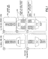
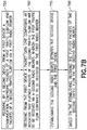
- Figure 1 shows packet handling from a transmitter to a receiver as performed in a 1.) Single DRB case, and in a 2.) New high priority DRB2.
- a data radio bearer DRB
- DRB data radio bearer
- the "split" function 110 will split the data into two DRBs, DRB 1 and DRB2.
- the prioritized data will be routed by the split function to DRB2.
- packets from the application that are to be prioritized are numbered e.g., 1, 2, 3.
- a first case i.e., single DRB case
- all the packets are transmitted in order and received at T(2).
- a second case a second DRB is created, and at T'(1), the packets #2 and #3 are handled by the new DRB.
- the packet #1 may be received by higher layers due to the reason that queues of high priority DRB are served first in receiver side, as discussed in above embodiment. However, packets sent via the low priority DRB may experience delay also in queues in transmitter side.
- An example embodiment of the invention allows keeping an in-sequence delivery of packets for a subflow that needs to be sent in another DRB, without requiring another sequence number.
- FIG. 2 illustrates a simplified block diagram illustrating some components of the wireless system shown in Figures 1 and 2 .
- a wireless network 235 is adapted for communication over a wireless link 232 with a first apparatus, such as a mobile communication device which may be referred to as an apparatus10, via second apparatus such as a network access node, e.g., a Node B (base station), and more specifically an apparatus 13 such as shown in Figure 2 .
- a first apparatus such as a mobile communication device which may be referred to as an apparatus10
- second apparatus such as a network access node, e.g., a Node B (base station)
- an apparatus 13 such as shown in Figure 2 .
- the network 235 may include a network node NN 240 that may include MME/S-GW and/or application server (AS) functionality, and which provides connectivity with a network, such as a telephone network and/or a data communications network (e.g., the internet 238).
- the NN 240 may include a WLAN access point as in accordance with an example embodiment of the invention.
- the first apparatus 10 comprise a controller, such as a computer or a data processor (DP) 214, a computer-readable memory medium embodied as a memory (MEM) 216 that stores a program of computer instructions (PROG) 218.
- the first apparatus may include also a suitable wireless interface, such as radio frequency (RF) transceiver 212, for bidirectional wireless communications with the second apparatus 13 using the data path 232.
- the PROG 218 can include computer instructions that, when executed by a processor, such as the DP 214, operates in accordance with example embodiments of the invention.
- the apparatus 13 also includes a controller, such as a computer or a data processor (DP) 224, a computer-readable memory medium embodied as a memory (MEM) 226 that stores a program of computer instructions (PROG) 228, to perform the operations in accordance with example embodiments of the invention as described herein.
- a controller such as a computer or a data processor (DP) 224, a computer-readable memory medium embodied as a memory (MEM) 226 that stores a program of computer instructions (PROG) 228, to perform the operations in accordance with example embodiments of the invention as described herein.
- a suitable wireless interface such as RF transceiver 222, for communication with the apparatus10 via one or more antennas is shown in Figure 2 .
- this wireless interface is not limiting as it may or may not be part of the apparatus 13 as shown.
- the apparatus 13 is coupled via a data/control path 234 to the NN 240.
- the path 234 may be implemented as an interface, such as an S1
- the apparatus 13 may also be coupled to other apparatus 15 via data/control path 236, which may be implemented as an interface.
- the other apparatus 15 may have similar configurations and components as the apparatus 13.
- this data/control path 234 can also be a wireless connection or can be a combination of wired and wireless connections.
- the NN 240 includes a controller and/or application server, such as a computer or a data processor (DP) 244, a computer-readable memory medium embodied as a memory (MEM) 246 that stores a program of computer instructions (PROG) 248 and possibly a suitable wireless interface, such as radio frequency (RF) transceiver 242, for bidirectional wireless communications with the apparatus 10 and the apparatus 13 via path 234.
- a controller and/or application server such as a computer or a data processor (DP) 244, a computer-readable memory medium embodied as a memory (MEM) 246 that stores a program of computer instructions (PROG) 248 and possibly a suitable wireless interface, such as radio frequency (RF) transceiver 242, for bidirectional wireless communications with the apparatus 10 and the apparatus 13 via path 234.
- DP data processor
- MEM memory
- PROG program of computer instructions
- RF radio frequency
- At least one of the PROGs 218, 228 and 248 is assumed to include program instructions that, when executed by the associated DP, enable the device to operate in accordance with example embodiments of this invention, as will be discussed below in greater detail. That is, various example embodiments of this invention may be implemented at least in part by computer software executable by the DP 214 of the apparatus 10; by the DP 224 of the apparatus 13; and/or by the DP 244 of the NN 240, or by hardware, or by a combination of software and hardware (and firmware).
- the apparatus 10 and the apparatus 13 may also include dedicated processors, for example Control module 215 and a corresponding Control module (CM) 225.
- Control module 215 and Control module 225 may be constructed so as to operate to perform at least the flow control operations as in accordance with various example embodiments in accordance with this invention.
- at least the Control modules 215 and 225 are configurable to perform at least the flow control operations as in accordance with various example embodiments in accordance with this invention
- the computer readable MEMs 216, 226 and 246 may be of any type suitable to the local technical environment and may be implemented using any suitable data storage technology, such as semiconductor based memory devices, flash memory, magnetic memory devices and systems, optical memory devices and systems, fixed memory and removable memory.
- the DPs 214, 224 and 244 may be of any type suitable to the local technical environment, and may include one or more of general purpose computers, special purpose computers, microprocessors, digital signal processors (DSPs) and processors based on a multicore processor architecture, as non-limiting examples.
- the wireless interfaces e.g., RF transceivers 212 and 222
- the example embodiments of the invention may assume that at least some packets of subflow X are sent via DRB1 before noticing that the flow requires DRB2 providing better QoS [or before being able to transmit packet of the flow to DRB2].
- Example embodiments of the invention work, for example, with a case of the addition of a second DRB (DRB2) when a first DRB (DRB1) is already established.
- All the packets belonging to the second sub flow are mapped to the second radio bearer from this moment on.
- the transmitter may become aware that the traffic comports two subflows after already starting transmission of second subflow. This may be for at least the reasons that:
- Flow Identification Indicator can use a Traffic Mark set by the CN UP on DL UP traffic sent to the (CAF-) RAN.
- This marking is based on rules received from the CN CP and may e.g. identify traffic of applications detected by the CN UP function and/or traffic subject of a specific charging.
- the FII marking is not meant to directly control the QoS behaviour in the RAN: the QoS behaviour in the RAN is controlled by QoS rules that may refer to FII and that are sent by the CN CP to the CAF-RAN.
- the FII is used on NG3 on a per-packet basis. Traffic to and from a UE may be associated with the same FII.
- different PDU within the same flow may be associated by the CN UP with different FII values. This assumes the transport protocol handles different streams for this kind of traffic
- a UE can determine the SSC mode required for an application using at least one of the following methods:
- a CAF-RAN node or device can perform these operations for new flow detection.
- the CAF-RAN can be incorporated in any of the devices apparatus 13, NN 240, and/or the apparatus 10 as shown in Figure 2 .
- detection may be performed by receiving a packet which comprises certain IP-5-tuple or marking (FII) set by CN entity.
- DL data packet itself comprises an indication that the packet is part of flow requiring higher priority.
- the CAF-RAN function can performs detection based on analytics of the application traffic based on one or more packets that identify the traffic type.
- detection of a new flow could be based on the analysis of several packets.
- the full identification of a new flow could be based on an analysis of a few consecutives packets. Note that this applies also to the case if packet marking is used: in an ongoing application flow, the application detection function (either in CN or in RAN) is able to detect the traffic type only after some time and then changes the packet marking. Then, the remaining packets of ongoing application traffic flow would need to be transferred over a new DRB.
- a QoS policy can also indicate that the identified flow requires higher priority.
- QoS framework and RRC handling of 5G can support detection of flows in Network side, and DRB configuration initiated by Network, which is then transferred to the UE.
- UE may create DRB by itself dynamically.
- Example embodiments of the invention work to provide a context and/or an application-aware function in RAN (e.g., in a base station). This provides the capability to separate flows based on several criteria, for example, from simple IP-5-tuple to advanced machine learning based approaches. Further, this function is able to guide RRC in NR BS to map traffic to DRBs. Additionally, this can also be done based on packet marking on RAN-CN IF, in case that such a function is (also) located in CN.
- a first operation in accordance with the example embodiments includes:
- the switch marker does not signal the end of the transmission, but only the end of part of it (the second flow).
- the packets continue to arrive in first RB. Which is not the case in prior art. If we apply prior art to the first option, the receiver would stop handling any packets coming from RB1.
- sequence number which is not present in prior art. This added sequence number is used because the packets may be received out of order in the receiving buffer, in case of split bearer for example. In prior art there is no possibility to have a split connection and thus out of order reception of packets.
- the transmitter is the eNB and the receiver is the UE, but the roles could be exchanged.
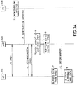
- Figure 3a illustrates a message flow in accordance with the first option of example embodiments of the invention. As shown in Figure 3a :
- the PDCP layer deliver to higher layers the SDU in the same order as they have been submitted.
- the SN is used to reorder the packets when lower layer (RLC) can't provide this function.
- the lower layer (RLC) provide in-order delivery.
- the PDCP layer reorders the PDU received out of order (because of the handover), based on the PDCP sequence number.
- the PDCP constantly re-order the PDCP PDU received from different radio links, based on the PDCP SN.
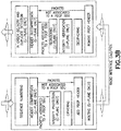
- FIG 3b represents the functional view of the PDCP entity for the PDCP sublayer which shows a PDCP layer. This figure is based on the radio interface protocol architecture. With regards to Figure 3b , the PDCP entities are located in the PDCP sublayer. Several PDCP entities may be defined for a UE. Each PDCP entity carrying user plane data may be configured to use header compression. Each PDCP entity is carrying the data of one radio bearer. In this version of the specification, only the robust header compression protocol (ROHC), is supported. Every PDCP entity uses at most one ROHC compressor instance and at most one ROHC decompressor instance. A PDCP entity is associated either to the control plane or the user plane depending on which radio bearer it is carrying data for.
- ROHC robust header compression protocol
- integrity protection and verification are also performed for the u-plane.
- routing is performed in transmitting PDCP entity, and reordering is performed in the receiving PDCP entity.
- routing is performed in the transmitting PDCP entity and reordering is performed in the receiving PDCP entity.
- the transmitting PDCP entity of the UE may only submit the PDCP PDUs to the associated AM RLC entity.
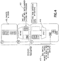
- Figure 4 shows an illustration of Packet handling in accordance with example embodiments of the invention.
- a new DRB is created and the split function will add the switch marker 430 to a packet after which DRB is going to be switched.
- the merge function will wait until the packet with the switch marker in the DRB1 is processed.
- all packets including the merged packets are scheduled with the DRB1 packets so that the packets are in an order of highest priority to lowest priority.
- Figure 5 illustrates another message flow in accordance with example embodiments of the invention. As shown in Figure 5 :
- confirmation of in-order reception of the packet data unit may be sent by the UE 510, wherein the transmitting the further packets of the second traffic flow is based on the confirmation.
- a split bearer e.g., 2 radio links
- the example embodiments may comprise one or more aspects of the following:
- example embodiments may comprise one or more aspects of the following:
- the example embodiments allow to keep the in-sequence delivery of packets for a subflow that needs to be sent in another DRB, without requiring another of Sequence Number.
- buffering may be done in receiver, until receiving message from transmitter that ok to send packets from DRB2 receiver buffer to higher layers.
- buffering may be done in transmitter, until receiving confirmation from receiver that ok to send packets via DRB2.
- Figure 6 shows another illustration of packet handling in accordance with example embodiments of the invention.
- a new DRB is created and as shown in block 615 the split function will add the switch marker to packet after which DRB is going to be switched.
- the merge function will wait until the receiver confirms the handling of packet with the switch-marker.
- all packets including the merged packets are scheduled in an order of highest priority to lowest priority.
- Figure 7a illustrates operations which may be performed by a network device such as, but not limited to, a base station or an apparatus such as the apparatus 13 and/or NN 240 as in Figure 2 .
- a network device such as, but not limited to, a base station or an apparatus such as the apparatus 13 and/or NN 240 as in Figure 2 .
- step 710 there is performing, by a first device, a communication comprising transmitting packets of a first traffic subflow and packets of a second traffic subflow via a first radio bearer to a second device; then as shown in step 720 there is detecting that further packets of the second traffic subflow are to be transmitted via a second radio bearer to the second device; then as shown in step 730 of Figure 7a there is, based on the detecting, transmitting a packet data unit of the second traffic subflow via the first radio bearer to the second device, wherein the packet data unit comprises an indication of a switch of the second traffic flow to the second radio bearer, and wherein packets of
- the detecting comprises detecting that the further packets of the second traffic subflow are associated with an application that requires a higher priority.
- the confirmation of reception may be confirmation of in-order reception of the packet data unit
- the transmitting the further packets of the second traffic flow is based on the confirmation
- the packet data unit comprises a sequence number.
- the sequence number causes in-sequence delivery of packets for the radio bearers at the second device.
- the packet data unit causes the second device to deliver the packets belonging to the second traffic subflow to a higher layer of the second device.
- the higher layer is an application layer.
- the packets are buffered at the first device.
- a non-transitory computer-readable medium (MEM 226 and/or MEM 246 as in Figure 2 ) storing program code (PROG 228 and/or PROG 248 as in Figure 2 ), the program code executed by at least one processor (DP 224 and/or DP 244 as in Figure 2 ) to perform the operations as at least described in the paragraphs above.
- an apparatus comprising: means for performing (DP 224, DP 225, and/or DP 244; PROG 228 and/or PROG 248; and MEM 226 and/or MEM 246 as in Figure 2 ), by a first device, a communication comprising transmitting packets of a first traffic subflow and packets of a second traffic subflow via a first radio bearer to a second device; means for detecting (DP 224, DP 225, and/or DP 244; PROG 228 and/or PROG 248; and MEM 226 and/or MEM 246 as in Figure 2 ) that further packets of the second traffic subflow are to be transmitted via a second radio bearer to the second device; means based on the detecting, for transmitting (DP 224, DP 225, and/or DP 244; PROG 228 and/or PROG 248; and MEM 226, MEM 246, and/or TRANS 222 as in Figure 2
- Figure 7b illustrates operations which may be performed by a device such as, but not limited to, a communication device (e.g., the apparatus 10 as in Figure 2 ).
- a communication device e.g., the apparatus 10 as in Figure 2
- step 750 there is receiving, by a second device, from a first device a communication comprising packets of a first traffic subflow and packets of a second traffic subflow via a first radio bearer;
- step 760 of Figure 7b there is receiving from the first device a packet data unit comprising an indication that further packets of the second traffic subflow are to be received via a second radio bearer, wherein the first traffic flow continues to be received via the first radio bearer ;
- step 770 there is establishing the second radio bearer between the second device and the first device ; and then as shown in step 780 of Figure 7b there is, based on the establishing, receiving the further packets of the second traffic flow via the second radio bearer.
- the confirmation of reception may be confirmation of in-order reception of the packet data unit, wherein the further packets of the second traffic flow is received based on the confirmation.
- the packet data unit comprises a sequence number.
- the sequence number enables in-sequence delivery of packets for the radio bearers.
- the packet data unit enables the second device to deliver the packets belonging to the second traffic subflow to a higher layer of the communication device.
- the higher layer is an application layer.
- the second traffic flow prior to receiving the packet data unit the second traffic flow is buffered at the second device, and wherein delivering the packets belonging to the traffic subflow to the higher layer is performed only after receiving the packet data unit.
- a non-transitory computer-readable medium (MEM 216 as in Figure 2 ) storing program code (PROG 218 as in Figure 2 ), the program code executed by at least one processor (DP 214 and/or DP 215 as in Figure 2 ) to perform the operations as at least described in the paragraphs above.
- an apparatus comprising: means for receiving (TRANS 212; DP 214 and/or DP 215; PROG 218; and MEM 216 as in Figure 2 ), by a second device, from a first device a communication comprising packets of a first traffic subflow and packets of a second traffic subflow via a first radio bearer; means for receiving (TRANS 212; DP 214 and/or DP 215; PROG 218; and MEM 216 as in Figure 2 ) from the first device a packet data unit comprising an indication that further packets of the second traffic subflow are to be received via a second radio bearer, wherein the first traffic flow continues to be received via the first radio bearer; means for establishing (TRANS 212; DP 214 and/or DP 215; PROG 218; and MEM 216 as in Figure 2 )the second radio bearer between the second device and the first device; and means for receiving (TRANS 212; DP 214
- an apparatus e.g., a first device performing a method comprising performing a communication comprising transmitting packets of a first traffic subflow and packets of a second traffic subflow via a first radio bearer to a second device; detecting that further packets of the second traffic subflow are to be transmitted via a second radio bearer to the second device; then, based on the detecting, transmitting a packet data unit via the first radio bearer to the second device, wherein the packet data unit comprises an indication of a switch of the second traffic flow to the second radio bearer, and wherein packets of the first traffic flow continues to be transmitted via the first radio bearer; and based on the second radio bearer being established between the first device and the second device, transmitting further packets of the second traffic flow via the second radio bearer to the second device.
- the apparatus performing a method comprising the method of the previous paragraph, there is: based on the detecting, causing the second device to establish the second radio bearer; receiving confirmation of reception of the packet data unit from the second device, wherein the confirmation of reception may be confirmation of in-order reception of the packet data unit, wherein the transmitting the second traffic flow is based on the confirmation;
- the packet data unit comprises a sequence number; the sequence number causes in-sequence delivery of packets for the radio bearers at the second device athe packet data unit causes the second device to deliver the packets belonging to the second traffic subflow to a higher layer of the second device; the higher layer is an application layer; and prior to transmitting the second traffic flow towards the second radio bearer of the second device, the packets are buffered at the first device.
- a non-transitory computer-readable medium (MEM 226 and/or MEM 246 as in Figure 2 ) storing program code (PROG 228 and/or PROG 248 as in Figure 2 ), the program code executed by at least one processor (DP 224 and/or DP 244 as in Figure 2 ) to perform the operations as at least described in the paragraphs above.
- an apparatus e.g., a second device performing a method comprising receiving from a first device a communication comprising packets of a first traffic subflow and packets of a second traffic subflow via a first radio bearer; receiving from the first device a packet data unit comprising an indication that further packets of the second traffic subflow are to be received via a second radio bearer, wherein the first traffic flow continues to be received via the first radio bearer; establishing the second radio bearer between the second device and the first device; and then, based on the establishing, receiving the further packets of the second traffic flow via the second radio bearer.
- the apparatus performing a method comprising the method of the previous paragraph, there is: receiving instructions to establish the different radio bearer; sending confirmation of reception of the packet data unit to the first device, wherein the confirmation of reception may be confirmation of in-order reception of the packet data unit, wherein the second traffic flow is received based on the confirmation;
- the packet data unit comprises a sequence number; the sequence number enables in-sequence delivery of packets for the second radio bearer on a priority of the packets;
- the packet data unit enables the second device to deliver the packets belonging to the second traffic subflow to a higher layer of the communication device; the higher layer is an application layer; and prior to receiving the packet data unit the second traffic flow is buffered at the second device, wherein delivering the packets belonging to the traffic subflow to the higher layer is performed only after receiving the packet data unit.
- a non-transitory computer-readable medium (MEM 216 as in Figure 2 ) storing program code (PROG 218 as in Figure 2 ), the program code executed by at least one processor (DP 214 and/or DP 215 as in Figure 2 ) to perform the operations as at least described in the paragraphs above.
- any reference to a particular user equipment (UE) and/or base station (eNB) performing an operation in accordance with the example embodiments is non-limiting. Any of the operations in accordance with the example embodiments of the invention may be performed by any suitable device or apparatus, and these suitable device or apparatus does not need to be a UE or eNB as described.
- UE user equipment
- eNB base station
- any reference to operations in accordance with the embodiments of the invention being directed to use with a particular radio network technology are not limiting.
- the example embodiments of the invention may be performed with any current, past, or future radio network technologies.
- the various embodiments may be implemented in hardware or special purpose circuits, software, logic or any combination thereof.
- some aspects may be implemented in hardware, while other aspects may be implemented in firmware or software which may be executed by a controller, microprocessor or other computing device, although the invention is not limited thereto.
- firmware or software which may be executed by a controller, microprocessor or other computing device, although the invention is not limited thereto.
- While various aspects of the invention may be illustrated and described as block diagrams, flow charts, or using some other pictorial representation, it is well understood that these blocks, apparatus, systems, techniques or methods described herein may be implemented in, as non-limiting examples, hardware, software, firmware, special purpose circuits or logic, general purpose hardware or controller or other computing devices, or some combination thereof.
- Embodiments of the inventions may be practiced in various components such as integrated circuit modules.
- the design of integrated circuits is by and large a highly automated process.
- Complex and powerful software tools are available for converting a logic level design into a semiconductor circuit design ready to be etched and formed on a semiconductor substrate.
- connection means any connection or coupling, either direct or indirect, between two or more elements, and may encompass the presence of one or more intermediate elements between two elements that are “connected” or “coupled” together.
- the coupling or connection between the elements can be physical, logical, or a combination thereof.
- two elements may be considered to be “connected” or “coupled” together by the use of one or more wires, cables and/or printed electrical connections, as well as by the use of electromagnetic energy, such as electromagnetic energy having wavelengths in the radio frequency region, the microwave region and the optical (both visible and invisible) region, as several non-limiting and non-exhaustive examples.
Landscapes
- Engineering & Computer Science (AREA)
- Computer Networks & Wireless Communication (AREA)
- Signal Processing (AREA)
- Computer Security & Cryptography (AREA)
- Mobile Radio Communication Systems (AREA)
- Input Circuits Of Receivers And Coupling Of Receivers And Audio Equipment (AREA)
- Radio Transmission System (AREA)
Priority Applications (5)
| Application Number | Priority Date | Filing Date | Title |
|---|---|---|---|
| DK21151381.7T DK3832976T3 (da) | 2016-09-29 | 2017-09-04 | Radiobæreromskiftning ved radioadgang |
| EP22207306.6A EP4181485B1 (en) | 2016-09-29 | 2017-09-04 | Radio bearer switching in radio access |
| EP24160970.0A EP4391706B1 (en) | 2016-09-29 | 2017-09-04 | Radio bearer switching in radio access |
| PL17769113T PL3520549T3 (pl) | 2016-09-29 | 2017-09-04 | Przełączanie nośników radiowych w dostępie radiowym |
| EP21151381.7A EP3832976B1 (en) | 2016-09-29 | 2017-09-04 | Radio bearer switching in radio access |
Applications Claiming Priority (2)
| Application Number | Priority Date | Filing Date | Title |
|---|---|---|---|
| US201662401385P | 2016-09-29 | 2016-09-29 | |
| PCT/FI2017/050619 WO2018060546A1 (en) | 2016-09-29 | 2017-09-04 | Radio bearer switching in radio access |
Related Child Applications (3)
| Application Number | Title | Priority Date | Filing Date |
|---|---|---|---|
| EP24160970.0A Division EP4391706B1 (en) | 2016-09-29 | 2017-09-04 | Radio bearer switching in radio access |
| EP22207306.6A Division EP4181485B1 (en) | 2016-09-29 | 2017-09-04 | Radio bearer switching in radio access |
| EP21151381.7A Division EP3832976B1 (en) | 2016-09-29 | 2017-09-04 | Radio bearer switching in radio access |
Publications (2)
| Publication Number | Publication Date |
|---|---|
| EP3520549A1 EP3520549A1 (en) | 2019-08-07 |
| EP3520549B1 true EP3520549B1 (en) | 2021-01-20 |
Family
ID=59914495
Family Applications (4)
| Application Number | Title | Priority Date | Filing Date |
|---|---|---|---|
| EP17769113.6A Active EP3520549B1 (en) | 2016-09-29 | 2017-09-04 | Radio bearer switching in radio access |
| EP22207306.6A Active EP4181485B1 (en) | 2016-09-29 | 2017-09-04 | Radio bearer switching in radio access |
| EP21151381.7A Active EP3832976B1 (en) | 2016-09-29 | 2017-09-04 | Radio bearer switching in radio access |
| EP24160970.0A Active EP4391706B1 (en) | 2016-09-29 | 2017-09-04 | Radio bearer switching in radio access |
Family Applications After (3)
| Application Number | Title | Priority Date | Filing Date |
|---|---|---|---|
| EP22207306.6A Active EP4181485B1 (en) | 2016-09-29 | 2017-09-04 | Radio bearer switching in radio access |
| EP21151381.7A Active EP3832976B1 (en) | 2016-09-29 | 2017-09-04 | Radio bearer switching in radio access |
| EP24160970.0A Active EP4391706B1 (en) | 2016-09-29 | 2017-09-04 | Radio bearer switching in radio access |
Country Status (25)
| Country | Link |
|---|---|
| US (4) | US10841829B2 (enExample) |
| EP (4) | EP3520549B1 (enExample) |
| JP (2) | JP6983877B2 (enExample) |
| KR (1) | KR102194522B1 (enExample) |
| CN (2) | CN109923845B (enExample) |
| AU (1) | AU2017334059B2 (enExample) |
| BR (1) | BR112019006321B1 (enExample) |
| CA (1) | CA3038577C (enExample) |
| CL (1) | CL2019000837A1 (enExample) |
| CO (1) | CO2019003026A2 (enExample) |
| DK (2) | DK3832976T3 (enExample) |
| ES (4) | ES3035700T3 (enExample) |
| FI (1) | FI3832976T3 (enExample) |
| HR (1) | HRP20250852T1 (enExample) |
| HU (3) | HUE071974T2 (enExample) |
| MX (2) | MX388079B (enExample) |
| MY (2) | MY203490A (enExample) |
| PH (3) | PH12022551579A1 (enExample) |
| PL (4) | PL3520549T3 (enExample) |
| PT (2) | PT3520549T (enExample) |
| RS (1) | RS66958B1 (enExample) |
| RU (1) | RU2724922C1 (enExample) |
| SM (1) | SMT202500252T1 (enExample) |
| WO (1) | WO2018060546A1 (enExample) |
| ZA (1) | ZA201902530B (enExample) |
Families Citing this family (12)
| Publication number | Priority date | Publication date | Assignee | Title |
|---|---|---|---|---|
| KR102194522B1 (ko) | 2016-09-29 | 2020-12-24 | 노키아 테크놀로지스 오와이 | 무선 액세스에서의 무선 베어러 스위칭 |
| CN110063084B (zh) * | 2016-10-07 | 2023-08-18 | Lg电子株式会社 | 在无线通信系统中选择会话和服务连续性模式的方法 |
| GB201621072D0 (en) | 2016-12-12 | 2017-01-25 | Samsung Electronics Co Ltd | NR QOS handling |
| EP3569013B1 (en) * | 2017-01-11 | 2021-05-19 | Telefonaktiebolaget LM Ericsson (publ) | 5g qos flow to radio bearer remapping |
| WO2018174521A1 (en) * | 2017-03-22 | 2018-09-27 | Lg Electronics Inc. | Method for transmitting ul packet based on quality of service (qos) framework in wireless communication system and a device therefor |
| WO2018182366A1 (ko) | 2017-03-30 | 2018-10-04 | 삼성전자 주식회사 | Tcp/ip를 고려한 데이터 처리 방법 |
| KR102293998B1 (ko) * | 2017-03-30 | 2021-08-27 | 삼성전자 주식회사 | Tcp/ip를 고려한 데이터 처리 방법 |
| US10708972B2 (en) * | 2017-08-17 | 2020-07-07 | Telefonaktiebolaget Lm Ericsson (Publ) | Radio link management in a split RAN architecture |
| US11310707B2 (en) * | 2018-04-13 | 2022-04-19 | Qualcomm Incorporated | Facilitating quality of service flow remapping utilizing a service data adaptation protocol layer |
| CN114501339B (zh) * | 2020-10-23 | 2022-11-08 | 大唐移动通信设备有限公司 | 多媒体广播业务的处理方法、装置及存储介质 |
| WO2024005334A1 (en) * | 2022-07-01 | 2024-01-04 | Lg Electronics Inc. | Method and apparatus for configuring multiple sub quality of service flows belonging to quality of service flow in wireless communication system |
| CN117692995A (zh) * | 2022-09-03 | 2024-03-12 | 上海朗帛通信技术有限公司 | 一种被用于无线通信的方法和设备 |
Family Cites Families (69)
| Publication number | Priority date | Publication date | Assignee | Title |
|---|---|---|---|---|
| CO4850605A1 (es) | 1999-03-30 | 1999-10-26 | Motorola Inc | Metodo y aparato para organizar y recuperar informacion comunicada en un sistema de comunicacion por radio |
| KR100752608B1 (ko) | 2003-06-27 | 2007-08-29 | 노키아 코포레이션 | 무선통신네트워크에서 자원 예약을 위한 방법 및 시스템 |
| KR100608844B1 (ko) | 2004-01-09 | 2006-08-08 | 엘지전자 주식회사 | VoIP 서비스를 제공하는 무선통신 시스템 |
| CN101047949B (zh) | 2006-03-27 | 2010-05-12 | 华为技术有限公司 | 业务数据流的承载控制方法 |
| CN101409951B (zh) | 2007-10-11 | 2010-08-25 | 华为技术有限公司 | 承载建立方法及相关装置 |
| US8718647B2 (en) | 2008-06-20 | 2014-05-06 | Qualcomm Incorporated | Method and apparatus for prioritizing status messages in a wireless communication system |
| US20100034083A1 (en) | 2008-08-08 | 2010-02-11 | Qualcomm Incorporated | Method and apparatus for packet differentiation in a wireless communication system |
| EP2214451B1 (en) | 2009-01-30 | 2012-10-03 | Alcatel Lucent | Method for managing resources in a wireless communication system, and control node for implementing the method |
| ES2810873T3 (es) | 2009-04-02 | 2021-03-09 | Ericsson Telefon Ab L M | Técnicas de gestión del tráfico de red |
| CN101932102B (zh) | 2009-06-19 | 2013-01-23 | 华为技术有限公司 | 业务承载映射方法及通信设备 |
| CN102640558A (zh) * | 2009-12-22 | 2012-08-15 | 富士通株式会社 | 在使用中继节点的通信系统中的传输 |
| KR101782647B1 (ko) | 2010-01-28 | 2017-09-28 | 엘지전자 주식회사 | 무선 통신 시스템에서 상향링크 제어 정보 인코딩 방법 및 장치 |
| DK2567524T3 (da) | 2010-05-03 | 2019-09-09 | Nokia Technologies Oy | Reduktion af protokolspild |
| US8891356B2 (en) | 2010-06-28 | 2014-11-18 | Qualcomm Incorporated | System and method for multi-point HSDPA communication utilizing a multi-link RLC sublayer |
| US10039032B2 (en) * | 2010-09-17 | 2018-07-31 | Xieon Networks S.A.R.L. | Method and device for processing data in a communication network |
| JP5812373B2 (ja) | 2011-07-01 | 2015-11-11 | ▲ホア▼▲ウェイ▼技術有限公司 | ベアラ処理のための方法及び装置 |
| CN102883441B (zh) * | 2011-07-15 | 2015-04-22 | 华为技术有限公司 | 一种无线宽带通信方法和装置 |
| US9883441B2 (en) | 2011-11-10 | 2018-01-30 | Nokia Technologies Oy | Method and apparatus to route packet flows over two transport radios |
| CN103166995B (zh) * | 2011-12-14 | 2016-08-10 | 华为技术有限公司 | 一种视频传输方法及装置 |
| US9071985B2 (en) | 2012-02-01 | 2015-06-30 | Qualcomm Incorporated | Apparatus and method for user equipment assisted congestion control |
| US9615388B2 (en) | 2012-03-19 | 2017-04-04 | Samsung Electronics Co., Ltd | Communication method and apparatus using wireless LAN access point |
| WO2013174422A1 (en) | 2012-05-23 | 2013-11-28 | Nokia Siemens Networks Oy | Methods, computer program products and apparatuses enabling symmetric bearer enforcement |
| IN2015DN03255A (enExample) * | 2012-11-09 | 2015-10-09 | Ericsson Telefon Ab L M | |
| CN104041110B (zh) | 2012-11-15 | 2018-03-02 | 华为技术有限公司 | 传输数据的方法、基站、接入网设备和用户设备 |
| CN103975642B (zh) | 2012-11-22 | 2018-08-21 | 华为技术有限公司 | 一种短距离通信的方法、设备和系统 |
| CN103889009A (zh) * | 2012-12-21 | 2014-06-25 | 华为技术有限公司 | 切换方法和设备 |
| CN103905378B (zh) * | 2012-12-25 | 2017-04-12 | 华为技术有限公司 | 一种传输数据的方法及装置 |
| EP2757855A1 (en) | 2013-01-17 | 2014-07-23 | Alcatel Lucent | Traffic Offload |
| CN104396302B (zh) | 2013-01-18 | 2018-10-30 | 华为技术有限公司 | 传输数据的方法、基站和用户设备 |
| CN105027511B (zh) * | 2013-03-04 | 2018-08-21 | 三星电子株式会社 | 在无线通信中用于并行化分组处理的方法和系统 |
| US9042369B2 (en) | 2013-03-13 | 2015-05-26 | Alcatel Lucent | System and method for reflecting FEC route information |
| KR102045332B1 (ko) | 2013-03-26 | 2019-11-18 | 삼성전자 주식회사 | 이동통신 시스템에서 무선랜을 이용해서 트래픽을 오프 로드하는 방법 및 장치 |
| JP6227881B2 (ja) | 2013-04-05 | 2017-11-08 | 株式会社Nttドコモ | 無線基地局 |
| US20140348080A1 (en) | 2013-05-21 | 2014-11-27 | Qualcomm Incorporated | Uplink traffic prioritization at a user equipment (ue) within the same bearer |
| US9650794B2 (en) | 2013-08-08 | 2017-05-16 | Intel IP Corporation | Apparatus, system and method of steering data radio bearer traffic to a wireless local area network link |
| US9560656B2 (en) | 2013-10-17 | 2017-01-31 | Qualcomm Incorporated | Joint support for UEs capable of communicating data of a same bearer on first and second RATs simultaneously and UEs not capable of communicating data of a same bearer on the first and second RATs simutaneously |
| CN105659690B (zh) * | 2013-10-21 | 2020-03-17 | Lg电子株式会社 | 在双连接中发送上行链路数据的方法及其设备 |
| KR20150061487A (ko) | 2013-11-27 | 2015-06-04 | 한국전자통신연구원 | 데이터 오프로딩 방법 |
| US9762702B2 (en) * | 2014-01-14 | 2017-09-12 | Apple Inc. | Multipath TCP signaling with application specific tags |
| CN104797000B (zh) * | 2014-01-21 | 2018-06-19 | 普天信息技术有限公司 | 双连接网络中的无线承载建立方法及系统 |
| US20150223107A1 (en) | 2014-01-31 | 2015-08-06 | Intel IP Corporation | User equipment and method for application specific packet filter |
| WO2015119547A1 (en) * | 2014-02-06 | 2015-08-13 | Telefonaktiebolaget Lm Ericsson (Publ) | Methods and apparatuses for handling communication in a communication system comprising an access point and a wire line network node connected via wire line to the access point |
| US20150245401A1 (en) | 2014-02-26 | 2015-08-27 | Google Technology Holdings LLC | Methods and apparatus for converting a single radio-access technology connection into a multiple radio-access technology connection |
| US9596707B2 (en) * | 2014-03-13 | 2017-03-14 | Intel Corporation | Bearer mobility and splitting in a radio access network-based, 3rd generation partnership project network having an integrated wireless local area network |
| US9787595B2 (en) | 2014-03-24 | 2017-10-10 | Intel IP Corporation | Evolved node-B and mobility management entity and user equipment and methods for supporting attended and unattended services |
| WO2015152659A1 (ko) | 2014-04-02 | 2015-10-08 | 삼성전자 주식회사 | 이동 통신 시스템에서 셀룰러 망과 무선랜 망 간 트래픽 스티어링 방법 및 장치 |
| US10716165B2 (en) * | 2014-04-24 | 2020-07-14 | Lg Electronics Inc. | Methods and apparatus for releasing a sidelink radio bearer for D2D communication system |
| GB2525416B (en) * | 2014-04-24 | 2017-11-01 | Samsung Electronics Co Ltd | Data transfer using a multipath TCP connection |
| BR112016025262A2 (pt) | 2014-04-30 | 2017-08-15 | Huawei Tech Co Ltd | sistema, aparelho e método correspondente para gerenciar recurso em rede compartilhada |
| US9860872B2 (en) | 2014-06-03 | 2018-01-02 | Intel Corporation | In-band control signaling for integrated WLAN/3GPP RAT architectures |
| US10542452B2 (en) | 2014-06-10 | 2020-01-21 | Apple Inc. | Enhancing quality of service for high priority services |
| US9392519B2 (en) | 2014-06-23 | 2016-07-12 | Intel Corporation | Apparatus, system and method of tunneling data radio bearers via a wireless local area network link |
| JP6415603B2 (ja) | 2014-06-30 | 2018-10-31 | インテル アイピー コーポレーション | Lte用のサービス品質アーキテクチャを改善する装置及び方法 |
| US9906973B2 (en) * | 2014-11-28 | 2018-02-27 | Industrial Technology Research Institute | Evolved NodeB and traffic dispatch method thereof |
| US10708810B2 (en) * | 2014-12-23 | 2020-07-07 | Interdigital Patent Holdings, Inc. | Methods for WiFi integration in cellular systems |
| US9591516B2 (en) | 2014-12-23 | 2017-03-07 | Motorola Solutions, Inc. | Method and apparatus for managing bearers in a wireless communication system |
| US9780997B2 (en) * | 2015-01-30 | 2017-10-03 | Alcatel Lucent | Method and system for controlling an operation of an application by classifying an application type using data bearer characteristics |
| US10070461B2 (en) * | 2015-05-15 | 2018-09-04 | Mediatek Inc. | QoS provisioning for LTE-WLAN aggregation |
| EP3308595B1 (en) | 2015-06-10 | 2021-08-18 | Telefonaktiebolaget LM Ericsson (publ) | Establishing an interaction session on a bearer in a radio communication network |
| EP3148285B1 (en) * | 2015-09-25 | 2019-04-17 | Panasonic Intellectual Property Corporation of America | Improved radio bearer mapping for proximity services ue to network relay with associated priority signalling |
| CN107295575B (zh) | 2016-04-01 | 2020-02-28 | 中兴通讯股份有限公司 | 一种服务质量的控制方法和装置 |
| CN107295564B (zh) | 2016-04-11 | 2023-12-05 | 中兴通讯股份有限公司 | 一种基于流的承载管理方法、数据传输方法及装置 |
| US10959240B2 (en) | 2016-04-15 | 2021-03-23 | Qualcomm Incorporated | Providing quality-of-service in wireless communications |
| US10911977B2 (en) | 2016-08-01 | 2021-02-02 | Samsung Electronics Co., Ltd. | Method and apparatus for managing data communication in wireless communication network |
| WO2018030798A1 (en) | 2016-08-09 | 2018-02-15 | Samsung Electronics Co., Ltd. | Method and apparatus for managing user plane operation in wireless communication system |
| CN110493823B (zh) | 2016-08-15 | 2020-09-04 | 华为技术有限公司 | 一种数据处理方法及装置 |
| JP6956477B2 (ja) | 2016-09-29 | 2021-11-02 | 株式会社Nttドコモ | 端末及び信号送信方法 |
| KR102194522B1 (ko) | 2016-09-29 | 2020-12-24 | 노키아 테크놀로지스 오와이 | 무선 액세스에서의 무선 베어러 스위칭 |
| EP3301845B1 (en) | 2016-09-30 | 2023-01-18 | Nokia Technologies Oy | Granting resources for uplink transmissions |
-
2017
- 2017-09-04 KR KR1020197010808A patent/KR102194522B1/ko active Active
- 2017-09-04 AU AU2017334059A patent/AU2017334059B2/en active Active
- 2017-09-04 ES ES24160970T patent/ES3035700T3/es active Active
- 2017-09-04 PL PL17769113T patent/PL3520549T3/pl unknown
- 2017-09-04 RU RU2019108881A patent/RU2724922C1/ru active
- 2017-09-04 SM SM20250252T patent/SMT202500252T1/it unknown
- 2017-09-04 WO PCT/FI2017/050619 patent/WO2018060546A1/en not_active Ceased
- 2017-09-04 BR BR112019006321-8A patent/BR112019006321B1/pt active IP Right Grant
- 2017-09-04 PL PL22207306.6T patent/PL4181485T3/pl unknown
- 2017-09-04 CN CN201780068889.9A patent/CN109923845B/zh active Active
- 2017-09-04 PT PT177691136T patent/PT3520549T/pt unknown
- 2017-09-04 CN CN202111191792.1A patent/CN113890901B/zh active Active
- 2017-09-04 CA CA3038577A patent/CA3038577C/en active Active
- 2017-09-04 HU HUE24160970A patent/HUE071974T2/hu unknown
- 2017-09-04 PH PH1/2022/551579A patent/PH12022551579A1/en unknown
- 2017-09-04 JP JP2019516593A patent/JP6983877B2/ja active Active
- 2017-09-04 EP EP17769113.6A patent/EP3520549B1/en active Active
- 2017-09-04 HU HUE17769113A patent/HUE053344T2/hu unknown
- 2017-09-04 MX MX2019003667A patent/MX388079B/es unknown
- 2017-09-04 EP EP22207306.6A patent/EP4181485B1/en active Active
- 2017-09-04 HU HUE21151381A patent/HUE061349T2/hu unknown
- 2017-09-04 MY MYPI2019001580A patent/MY203490A/en unknown
- 2017-09-04 MY MYPI2022003411A patent/MY208915A/en unknown
- 2017-09-04 PL PL21151381.7T patent/PL3832976T3/pl unknown
- 2017-09-04 ES ES22207306T patent/ES2976082T3/es active Active
- 2017-09-04 PH PH1/2022/552958A patent/PH12022552958A1/en unknown
- 2017-09-04 US US16/338,124 patent/US10841829B2/en active Active
- 2017-09-04 ES ES17769113T patent/ES2854985T3/es active Active
- 2017-09-04 EP EP21151381.7A patent/EP3832976B1/en active Active
- 2017-09-04 HR HRP20250852TT patent/HRP20250852T1/hr unknown
- 2017-09-04 PL PL24160970.0T patent/PL4391706T3/pl unknown
- 2017-09-04 DK DK21151381.7T patent/DK3832976T3/da active
- 2017-09-04 EP EP24160970.0A patent/EP4391706B1/en active Active
- 2017-09-04 FI FIEP21151381.7T patent/FI3832976T3/fi active
- 2017-09-04 ES ES21151381T patent/ES2938796T3/es active Active
- 2017-09-04 PT PT211513817T patent/PT3832976T/pt unknown
- 2017-09-04 RS RS20250642A patent/RS66958B1/sr unknown
- 2017-09-04 DK DK17769113.6T patent/DK3520549T3/da active
-
2019
- 2019-03-25 PH PH12019500653A patent/PH12019500653A1/en unknown
- 2019-03-28 MX MX2021014132A patent/MX2021014132A/es unknown
- 2019-03-28 CL CL2019000837A patent/CL2019000837A1/es unknown
- 2019-03-28 CO CONC2019/0003026A patent/CO2019003026A2/es unknown
- 2019-04-23 ZA ZA2019/02530A patent/ZA201902530B/en unknown
-
2020
- 2020-10-12 US US17/068,421 patent/US11553369B2/en active Active
-
2021
- 2021-11-24 JP JP2021190361A patent/JP7200338B2/ja active Active
-
2022
- 2022-11-23 US US18/058,566 patent/US12101659B2/en active Active
-
2024
- 2024-08-26 US US18/814,710 patent/US20240422612A1/en active Pending
Non-Patent Citations (1)
| Title |
|---|
| None * |
Also Published As
Similar Documents
| Publication | Publication Date | Title |
|---|---|---|
| US12101659B2 (en) | Radio bearer switching in radio access | |
| US11696202B2 (en) | Communication method, base station, terminal device, and system | |
| US11601227B2 (en) | Duplication and rlc operation in new radio access technology | |
| JP6496075B2 (ja) | 第1の基地局又は第2の基地局を選択してユーザ装置(ue)にパケットデータユニット(pdu)を送信する方法及び装置 | |
| CN108370523B (zh) | 来自接收分流承载的用户设备的流量控制反馈 | |
| HK40108428A (en) | Radio bearer switching in radio access | |
| HK40108428B (en) | Radio bearer switching in radio access |
Legal Events
| Date | Code | Title | Description |
|---|---|---|---|
| STAA | Information on the status of an ep patent application or granted ep patent |
Free format text: STATUS: UNKNOWN |
|
| STAA | Information on the status of an ep patent application or granted ep patent |
Free format text: STATUS: THE INTERNATIONAL PUBLICATION HAS BEEN MADE |
|
| PUAI | Public reference made under article 153(3) epc to a published international application that has entered the european phase |
Free format text: ORIGINAL CODE: 0009012 |
|
| STAA | Information on the status of an ep patent application or granted ep patent |
Free format text: STATUS: REQUEST FOR EXAMINATION WAS MADE |
|
| 17P | Request for examination filed |
Effective date: 20190325 |
|
| AK | Designated contracting states |
Kind code of ref document: A1 Designated state(s): AL AT BE BG CH CY CZ DE DK EE ES FI FR GB GR HR HU IE IS IT LI LT LU LV MC MK MT NL NO PL PT RO RS SE SI SK SM TR |
|
| AX | Request for extension of the european patent |
Extension state: BA ME |
|
| RAP1 | Party data changed (applicant data changed or rights of an application transferred) |
Owner name: NOKIA TECHNOLOGIES OY |
|
| DAV | Request for validation of the european patent (deleted) | ||
| DAX | Request for extension of the european patent (deleted) | ||
| RIC1 | Information provided on ipc code assigned before grant |
Ipc: H04W 28/02 20090101ALI20200227BHEP Ipc: H04W 76/20 20180101ALI20200227BHEP Ipc: H04L 29/06 20060101AFI20200227BHEP |
|
| GRAJ | Information related to disapproval of communication of intention to grant by the applicant or resumption of examination proceedings by the epo deleted |
Free format text: ORIGINAL CODE: EPIDOSDIGR1 |
|
| GRAP | Despatch of communication of intention to grant a patent |
Free format text: ORIGINAL CODE: EPIDOSNIGR1 |
|
| GRAP | Despatch of communication of intention to grant a patent |
Free format text: ORIGINAL CODE: EPIDOSNIGR1 |
|
| STAA | Information on the status of an ep patent application or granted ep patent |
Free format text: STATUS: GRANT OF PATENT IS INTENDED |
|
| INTG | Intention to grant announced |
Effective date: 20200421 |
|
| GRAJ | Information related to disapproval of communication of intention to grant by the applicant or resumption of examination proceedings by the epo deleted |
Free format text: ORIGINAL CODE: EPIDOSDIGR1 |
|
| STAA | Information on the status of an ep patent application or granted ep patent |
Free format text: STATUS: REQUEST FOR EXAMINATION WAS MADE |
|
| REG | Reference to a national code |
Ref country code: DE Ref legal event code: R079 Ref document number: 602017031714 Country of ref document: DE Free format text: PREVIOUS MAIN CLASS: H04W0076100000 Ipc: H04L0029080000 |
|
| INTC | Intention to grant announced (deleted) | ||
| GRAP | Despatch of communication of intention to grant a patent |
Free format text: ORIGINAL CODE: EPIDOSNIGR1 |
|
| STAA | Information on the status of an ep patent application or granted ep patent |
Free format text: STATUS: GRANT OF PATENT IS INTENDED |
|
| RIC1 | Information provided on ipc code assigned before grant |
Ipc: H04W 28/02 20090101ALI20200608BHEP Ipc: H04L 29/08 20060101AFI20200608BHEP Ipc: H04L 29/06 20060101ALI20200608BHEP Ipc: H04W 76/20 20180101ALI20200608BHEP |
|
| INTG | Intention to grant announced |
Effective date: 20200629 |
|
| GRAJ | Information related to disapproval of communication of intention to grant by the applicant or resumption of examination proceedings by the epo deleted |
Free format text: ORIGINAL CODE: EPIDOSDIGR1 |
|
| STAA | Information on the status of an ep patent application or granted ep patent |
Free format text: STATUS: REQUEST FOR EXAMINATION WAS MADE |
|
| GRAS | Grant fee paid |
Free format text: ORIGINAL CODE: EPIDOSNIGR3 |
|
| STAA | Information on the status of an ep patent application or granted ep patent |
Free format text: STATUS: GRANT OF PATENT IS INTENDED |
|
| GRAP | Despatch of communication of intention to grant a patent |
Free format text: ORIGINAL CODE: EPIDOSNIGR1 |
|
| INTC | Intention to grant announced (deleted) | ||
| GRAA | (expected) grant |
Free format text: ORIGINAL CODE: 0009210 |
|
| STAA | Information on the status of an ep patent application or granted ep patent |
Free format text: STATUS: THE PATENT HAS BEEN GRANTED |
|
| INTG | Intention to grant announced |
Effective date: 20201126 |
|
| AK | Designated contracting states |
Kind code of ref document: B1 Designated state(s): AL AT BE BG CH CY CZ DE DK EE ES FI FR GB GR HR HU IE IS IT LI LT LU LV MC MK MT NL NO PL PT RO RS SE SI SK SM TR |
|
| REG | Reference to a national code |
Ref country code: GB Ref legal event code: FG4D |
|
| REG | Reference to a national code |
Ref country code: CH Ref legal event code: NV Representative=s name: NOVAGRAAF INTERNATIONAL SA, CH Ref country code: CH Ref legal event code: EP |
|
| REG | Reference to a national code |
Ref country code: PT Ref legal event code: SC4A Ref document number: 3520549 Country of ref document: PT Date of ref document: 20210202 Kind code of ref document: T Free format text: AVAILABILITY OF NATIONAL TRANSLATION Effective date: 20210127 |
|
| REG | Reference to a national code |
Ref country code: DE Ref legal event code: R096 Ref document number: 602017031714 Country of ref document: DE |
|
| REG | Reference to a national code |
Ref country code: RO Ref legal event code: EPE |
|
| REG | Reference to a national code |
Ref country code: AT Ref legal event code: REF Ref document number: 1357338 Country of ref document: AT Kind code of ref document: T Effective date: 20210215 |
|
| REG | Reference to a national code |
Ref country code: IE Ref legal event code: FG4D |
|
| REG | Reference to a national code |
Ref country code: FI Ref legal event code: FGE |
|
| REG | Reference to a national code |
Ref country code: DK Ref legal event code: T3 Effective date: 20210216 |
|
| REG | Reference to a national code |
Ref country code: SE Ref legal event code: TRGR |
|
| REG | Reference to a national code |
Ref country code: NL Ref legal event code: FP |
|
| REG | Reference to a national code |
Ref country code: GR Ref legal event code: EP Ref document number: 20210400383 Country of ref document: GR Effective date: 20210316 |
|
| REG | Reference to a national code |
Ref country code: EE Ref legal event code: FG4A Ref document number: E020493 Country of ref document: EE Effective date: 20210215 |
|
| REG | Reference to a national code |
Ref country code: HU Ref legal event code: AG4A Ref document number: E053344 Country of ref document: HU |
|
| REG | Reference to a national code |
Ref country code: LT Ref legal event code: MG9D |
|
| PG25 | Lapsed in a contracting state [announced via postgrant information from national office to epo] |
Ref country code: NO Free format text: LAPSE BECAUSE OF FAILURE TO SUBMIT A TRANSLATION OF THE DESCRIPTION OR TO PAY THE FEE WITHIN THE PRESCRIBED TIME-LIMIT Effective date: 20210420 Ref country code: HR Free format text: LAPSE BECAUSE OF FAILURE TO SUBMIT A TRANSLATION OF THE DESCRIPTION OR TO PAY THE FEE WITHIN THE PRESCRIBED TIME-LIMIT Effective date: 20210120 Ref country code: LT Free format text: LAPSE BECAUSE OF FAILURE TO SUBMIT A TRANSLATION OF THE DESCRIPTION OR TO PAY THE FEE WITHIN THE PRESCRIBED TIME-LIMIT Effective date: 20210120 Ref country code: BG Free format text: LAPSE BECAUSE OF FAILURE TO SUBMIT A TRANSLATION OF THE DESCRIPTION OR TO PAY THE FEE WITHIN THE PRESCRIBED TIME-LIMIT Effective date: 20210420 |
|
| PG25 | Lapsed in a contracting state [announced via postgrant information from national office to epo] |
Ref country code: RS Free format text: LAPSE BECAUSE OF FAILURE TO SUBMIT A TRANSLATION OF THE DESCRIPTION OR TO PAY THE FEE WITHIN THE PRESCRIBED TIME-LIMIT Effective date: 20210120 Ref country code: LV Free format text: LAPSE BECAUSE OF FAILURE TO SUBMIT A TRANSLATION OF THE DESCRIPTION OR TO PAY THE FEE WITHIN THE PRESCRIBED TIME-LIMIT Effective date: 20210120 |
|
| REG | Reference to a national code |
Ref country code: ES Ref legal event code: FG2A Ref document number: 2854985 Country of ref document: ES Kind code of ref document: T3 Effective date: 20210923 |
|
| PG25 | Lapsed in a contracting state [announced via postgrant information from national office to epo] |
Ref country code: IS Free format text: LAPSE BECAUSE OF FAILURE TO SUBMIT A TRANSLATION OF THE DESCRIPTION OR TO PAY THE FEE WITHIN THE PRESCRIBED TIME-LIMIT Effective date: 20210520 |
|
| REG | Reference to a national code |
Ref country code: DE Ref legal event code: R097 Ref document number: 602017031714 Country of ref document: DE |
|
| PG25 | Lapsed in a contracting state [announced via postgrant information from national office to epo] |
Ref country code: SM Free format text: LAPSE BECAUSE OF FAILURE TO SUBMIT A TRANSLATION OF THE DESCRIPTION OR TO PAY THE FEE WITHIN THE PRESCRIBED TIME-LIMIT Effective date: 20210120 Ref country code: CZ Free format text: LAPSE BECAUSE OF FAILURE TO SUBMIT A TRANSLATION OF THE DESCRIPTION OR TO PAY THE FEE WITHIN THE PRESCRIBED TIME-LIMIT Effective date: 20210120 |
|
| PLBE | No opposition filed within time limit |
Free format text: ORIGINAL CODE: 0009261 |
|
| REG | Reference to a national code |
Ref country code: DE Ref legal event code: R079 Ref document number: 602017031714 Country of ref document: DE Free format text: PREVIOUS MAIN CLASS: H04L0029080000 Ipc: H04L0065000000 |
|
| STAA | Information on the status of an ep patent application or granted ep patent |
Free format text: STATUS: NO OPPOSITION FILED WITHIN TIME LIMIT |
|
| PG25 | Lapsed in a contracting state [announced via postgrant information from national office to epo] |
Ref country code: SK Free format text: LAPSE BECAUSE OF FAILURE TO SUBMIT A TRANSLATION OF THE DESCRIPTION OR TO PAY THE FEE WITHIN THE PRESCRIBED TIME-LIMIT Effective date: 20210120 |
|
| 26N | No opposition filed |
Effective date: 20211021 |
|
| PG25 | Lapsed in a contracting state [announced via postgrant information from national office to epo] |
Ref country code: AL Free format text: LAPSE BECAUSE OF FAILURE TO SUBMIT A TRANSLATION OF THE DESCRIPTION OR TO PAY THE FEE WITHIN THE PRESCRIBED TIME-LIMIT Effective date: 20210120 |
|
| PG25 | Lapsed in a contracting state [announced via postgrant information from national office to epo] |
Ref country code: SI Free format text: LAPSE BECAUSE OF FAILURE TO SUBMIT A TRANSLATION OF THE DESCRIPTION OR TO PAY THE FEE WITHIN THE PRESCRIBED TIME-LIMIT Effective date: 20210120 |
|
| PG25 | Lapsed in a contracting state [announced via postgrant information from national office to epo] |
Ref country code: IS Free format text: LAPSE BECAUSE OF FAILURE TO SUBMIT A TRANSLATION OF THE DESCRIPTION OR TO PAY THE FEE WITHIN THE PRESCRIBED TIME-LIMIT Effective date: 20210520 Ref country code: MC Free format text: LAPSE BECAUSE OF FAILURE TO SUBMIT A TRANSLATION OF THE DESCRIPTION OR TO PAY THE FEE WITHIN THE PRESCRIBED TIME-LIMIT Effective date: 20210120 |
|
| PG25 | Lapsed in a contracting state [announced via postgrant information from national office to epo] |
Ref country code: LU Free format text: LAPSE BECAUSE OF NON-PAYMENT OF DUE FEES Effective date: 20210904 |
|
| REG | Reference to a national code |
Ref country code: AT Ref legal event code: UEP Ref document number: 1357338 Country of ref document: AT Kind code of ref document: T Effective date: 20210120 |
|
| PG25 | Lapsed in a contracting state [announced via postgrant information from national office to epo] |
Ref country code: CY Free format text: LAPSE BECAUSE OF FAILURE TO SUBMIT A TRANSLATION OF THE DESCRIPTION OR TO PAY THE FEE WITHIN THE PRESCRIBED TIME-LIMIT Effective date: 20210120 |
|
| P01 | Opt-out of the competence of the unified patent court (upc) registered |
Effective date: 20230527 |
|
| PG25 | Lapsed in a contracting state [announced via postgrant information from national office to epo] |
Ref country code: MK Free format text: LAPSE BECAUSE OF FAILURE TO SUBMIT A TRANSLATION OF THE DESCRIPTION OR TO PAY THE FEE WITHIN THE PRESCRIBED TIME-LIMIT Effective date: 20210120 |
|
| PG25 | Lapsed in a contracting state [announced via postgrant information from national office to epo] |
Ref country code: MT Free format text: LAPSE BECAUSE OF FAILURE TO SUBMIT A TRANSLATION OF THE DESCRIPTION OR TO PAY THE FEE WITHIN THE PRESCRIBED TIME-LIMIT Effective date: 20210120 |
|
| PGFP | Annual fee paid to national office [announced via postgrant information from national office to epo] |
Ref country code: NL Payment date: 20250814 Year of fee payment: 9 |
|
| REG | Reference to a national code |
Ref country code: CH Ref legal event code: U11 Free format text: ST27 STATUS EVENT CODE: U-0-0-U10-U11 (AS PROVIDED BY THE NATIONAL OFFICE) Effective date: 20251001 |
|
| PGFP | Annual fee paid to national office [announced via postgrant information from national office to epo] |
Ref country code: PT Payment date: 20250903 Year of fee payment: 9 Ref country code: FI Payment date: 20250912 Year of fee payment: 9 |
|
| PGFP | Annual fee paid to national office [announced via postgrant information from national office to epo] |
Ref country code: DE Payment date: 20250730 Year of fee payment: 9 Ref country code: DK Payment date: 20250911 Year of fee payment: 9 |
|
| PGFP | Annual fee paid to national office [announced via postgrant information from national office to epo] |
Ref country code: GR Payment date: 20250818 Year of fee payment: 9 |
|
| PGFP | Annual fee paid to national office [announced via postgrant information from national office to epo] |
Ref country code: TR Payment date: 20250902 Year of fee payment: 9 Ref country code: PL Payment date: 20250805 Year of fee payment: 9 Ref country code: IT Payment date: 20250825 Year of fee payment: 9 |
|
| PGFP | Annual fee paid to national office [announced via postgrant information from national office to epo] |
Ref country code: BE Payment date: 20250818 Year of fee payment: 9 Ref country code: HU Payment date: 20250828 Year of fee payment: 9 Ref country code: GB Payment date: 20250731 Year of fee payment: 9 |
|
| PGFP | Annual fee paid to national office [announced via postgrant information from national office to epo] |
Ref country code: FR Payment date: 20250808 Year of fee payment: 9 Ref country code: AT Payment date: 20250827 Year of fee payment: 9 |
|
| PGFP | Annual fee paid to national office [announced via postgrant information from national office to epo] |
Ref country code: SE Payment date: 20250812 Year of fee payment: 9 |
|
| PGFP | Annual fee paid to national office [announced via postgrant information from national office to epo] |
Ref country code: IE Payment date: 20250812 Year of fee payment: 9 Ref country code: EE Payment date: 20250808 Year of fee payment: 9 |
|
| PGFP | Annual fee paid to national office [announced via postgrant information from national office to epo] |
Ref country code: RO Payment date: 20250828 Year of fee payment: 9 |
|
| PGFP | Annual fee paid to national office [announced via postgrant information from national office to epo] |
Ref country code: CH Payment date: 20251001 Year of fee payment: 9 |
|
| PGFP | Annual fee paid to national office [announced via postgrant information from national office to epo] |
Ref country code: ES Payment date: 20251015 Year of fee payment: 9 |