EP3520164B1 - Production of electrical energy storage devices - Google Patents
Production of electrical energy storage devices Download PDFInfo
- Publication number
- EP3520164B1 EP3520164B1 EP17808178.2A EP17808178A EP3520164B1 EP 3520164 B1 EP3520164 B1 EP 3520164B1 EP 17808178 A EP17808178 A EP 17808178A EP 3520164 B1 EP3520164 B1 EP 3520164B1
- Authority
- EP
- European Patent Office
- Prior art keywords
- electrodes
- separator
- electrode
- group
- arranging
- Prior art date
- Legal status (The legal status is an assumption and is not a legal conclusion. Google has not performed a legal analysis and makes no representation as to the accuracy of the status listed.)
- Active
Links
- 238000004519 manufacturing process Methods 0.000 title claims description 39
- 238000004146 energy storage Methods 0.000 title claims description 21
- 238000000034 method Methods 0.000 claims description 38
- 230000008878 coupling Effects 0.000 claims description 4
- 238000010168 coupling process Methods 0.000 claims description 4
- 238000005859 coupling reaction Methods 0.000 claims description 4
- 238000003475 lamination Methods 0.000 claims description 3
- 238000005520 cutting process Methods 0.000 description 8
- 238000010030 laminating Methods 0.000 description 6
- 239000000463 material Substances 0.000 description 4
- HBBGRARXTFLTSG-UHFFFAOYSA-N Lithium ion Chemical compound [Li+] HBBGRARXTFLTSG-UHFFFAOYSA-N 0.000 description 3
- 229910001416 lithium ion Inorganic materials 0.000 description 3
- 239000000047 product Substances 0.000 description 3
- 230000007547 defect Effects 0.000 description 2
- 230000015572 biosynthetic process Effects 0.000 description 1
- 238000010586 diagram Methods 0.000 description 1
- 239000012467 final product Substances 0.000 description 1
- 238000003698 laser cutting Methods 0.000 description 1
- 229920000642 polymer Polymers 0.000 description 1
- 238000000926 separation method Methods 0.000 description 1
Images


Classifications
-
- H—ELECTRICITY
- H01—ELECTRIC ELEMENTS
- H01M—PROCESSES OR MEANS, e.g. BATTERIES, FOR THE DIRECT CONVERSION OF CHEMICAL ENERGY INTO ELECTRICAL ENERGY
- H01M10/00—Secondary cells; Manufacture thereof
- H01M10/04—Construction or manufacture in general
- H01M10/0404—Machines for assembling batteries
-
- H—ELECTRICITY
- H01—ELECTRIC ELEMENTS
- H01M—PROCESSES OR MEANS, e.g. BATTERIES, FOR THE DIRECT CONVERSION OF CHEMICAL ENERGY INTO ELECTRICAL ENERGY
- H01M10/00—Secondary cells; Manufacture thereof
- H01M10/04—Construction or manufacture in general
- H01M10/0459—Cells or batteries with folded separator between plate-like electrodes
-
- H—ELECTRICITY
- H01—ELECTRIC ELEMENTS
- H01M—PROCESSES OR MEANS, e.g. BATTERIES, FOR THE DIRECT CONVERSION OF CHEMICAL ENERGY INTO ELECTRICAL ENERGY
- H01M50/00—Constructional details or processes of manufacture of the non-active parts of electrochemical cells other than fuel cells, e.g. hybrid cells
- H01M50/40—Separators; Membranes; Diaphragms; Spacing elements inside cells
-
- H—ELECTRICITY
- H01—ELECTRIC ELEMENTS
- H01M—PROCESSES OR MEANS, e.g. BATTERIES, FOR THE DIRECT CONVERSION OF CHEMICAL ENERGY INTO ELECTRICAL ENERGY
- H01M10/00—Secondary cells; Manufacture thereof
- H01M10/05—Accumulators with non-aqueous electrolyte
- H01M10/058—Construction or manufacture
- H01M10/0583—Construction or manufacture of accumulators with folded construction elements except wound ones, i.e. folded positive or negative electrodes or separators, e.g. with "Z"-shaped electrodes or separators
-
- Y—GENERAL TAGGING OF NEW TECHNOLOGICAL DEVELOPMENTS; GENERAL TAGGING OF CROSS-SECTIONAL TECHNOLOGIES SPANNING OVER SEVERAL SECTIONS OF THE IPC; TECHNICAL SUBJECTS COVERED BY FORMER USPC CROSS-REFERENCE ART COLLECTIONS [XRACs] AND DIGESTS
- Y02—TECHNOLOGIES OR APPLICATIONS FOR MITIGATION OR ADAPTATION AGAINST CLIMATE CHANGE
- Y02E—REDUCTION OF GREENHOUSE GAS [GHG] EMISSIONS, RELATED TO ENERGY GENERATION, TRANSMISSION OR DISTRIBUTION
- Y02E60/00—Enabling technologies; Technologies with a potential or indirect contribution to GHG emissions mitigation
- Y02E60/10—Energy storage using batteries
-
- Y—GENERAL TAGGING OF NEW TECHNOLOGICAL DEVELOPMENTS; GENERAL TAGGING OF CROSS-SECTIONAL TECHNOLOGIES SPANNING OVER SEVERAL SECTIONS OF THE IPC; TECHNICAL SUBJECTS COVERED BY FORMER USPC CROSS-REFERENCE ART COLLECTIONS [XRACs] AND DIGESTS
- Y02—TECHNOLOGIES OR APPLICATIONS FOR MITIGATION OR ADAPTATION AGAINST CLIMATE CHANGE
- Y02P—CLIMATE CHANGE MITIGATION TECHNOLOGIES IN THE PRODUCTION OR PROCESSING OF GOODS
- Y02P70/00—Climate change mitigation technologies in the production process for final industrial or consumer products
- Y02P70/50—Manufacturing or production processes characterised by the final manufactured product
Description
- The invention relates to a method and an apparatus for the production of electrical energy storage devices.
- Specifically, but not exclusively, the invention can be applied to producing batteries, for example lithium ion batteries or polymer lithium ion batteries.
- In particular, reference is made to the production of electrical energy storage devices by forming a plurality of single cells, each of which consists of two (cathode or anode) electrodes alternated with two separating portions. The single cells are then connected together (in series).
- The prior art comprises many examples of methods for the production of electrical energy storage devices.
- Patent publication
US 2008/0280208 A1 discloses a method for producing an electrochemical device that comprises a single continuous separating element that is folded several times on itself to separate anodes and cathodes. - Patent publication
WO 02/095858 - Patent publication
US 2002/0007552 A1 discloses a method for the production of battery cells from at least one tape of material for anodes, one tape of material for cathodes and two separating tapes. - Patent publication
US 2014/0134472 A1 discloses a cell for a secondary battery comprising a stack formed in sequence by a first electrode / separator / second electrode / separator / first electrode and by an outer separator stacked on each first electrode. - Patent publication
US 2016/006072 A1 discloses a method for producing a secondary battery comprising feeding two separating tapes with four sets of electrodes to a stacking area. - Various aspects of the prior art of the production of electrical energy storage devices are improvable. Firstly, it is desirable to increase productivity. It is further desirable to improve manufacturing precision to obtain high quality electrical energy storage devices.
- One object of the invention is to provide a method and/or an apparatus for the production of electrical energy storage devices that is able to remedy one or more of the aforesaid limits and drawbacks of the prior art.
- One advantage is to enable electrical energy storage devices to be produced with high productivity.
- One advantage is to enable electrical energy storage devices of high quality to be produced.
- One advantage is the production of electrical energy storage devices formed of a plurality of single cells, in which the end electrodes are always anodes without the need to overturn the cells in the productive process.
- One advantage is to provide a constructionally cheap and simple apparatus for producing electrical energy storage devices.
- These objects and advantages and still others are achieved by an apparatus and/or by a method according to one or more of the claims set out below.
- In one embodiment, a method for the production of electrical energy storage devices comprises the steps of feeding two separators that are next to one another, arranging a succession of anodes one after the other between the two separators, arranging a succession of cathodes one after the other on the two outer sides of the two separators in an alternate manner by superimposing a cathode on each anode. The method may comprise the step of separating various single elements, each of which comprises a (single) anode and a (single) cathode with the interposition of portions of the two separators.
- In one embodiment, an apparatus for the production of electrical energy storage devices comprises two feeders of two separators that are next to one another, two anode feeders configured for arranging alternately a succession of anodes one after the other between the two separators, two cathode feeders configured for arranging a succession of cathodes one after the other on the two outer sides of the two separators alternately by superimposing a cathode on each anode. The apparatus may comprise a device for separating various single elements, each comprising a (single) anode and a (single) cathode with the interposition of portions of the two separators.
- The invention can be better understood and implemented with reference to the attached drawings that illustrate one embodiment thereof by way of non-limiting example, in which:
-
Figure 1 is a diagram, according to a raised vertical view, of one embodiment of an apparatus for the production of electrical energy storage devices made according to the present invention; -
Figures 2 and 3 show two enlarged details ofFigure 1 ; -
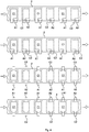
Figure 4 shows, according to top plan views, certain embodiments of configurations that electrodes may adopt during the advancement of the apparatus ofFigure 1 . - With 1, overall an apparatus has been indicated for the production of electrical energy storage devices.
- The production apparatus 1 may comprise, in particular, means for feeding a
first separator 2 and asecond separator 3 that are next to one another along a (preset) advancement path. Thefirst separator 2 may comprise a separator material in the form of a continuous tape. Thesecond separator 3 may comprise a separator material in the form of a continuous tape. - The means for feeding the first and the
second separators first feeder 4 arranged for feeding the first tape-shaped separator 2. The means for feeding the first and the second separators may comprise, in particular, at least onesecond feeder 5 arranged for feeding the second tape-shaped separator 3. Thefirst feeder 4 may comprise, for example, a (known) device for unwinding at least one tape from at least one reel. Thesecond feeder 5 may comprise, for example, a (known) device for unwinding at least one tape from at least one reel. Thefirst feeder 4 may operate, in particular, with continuous and/or intermittent advancement. Thesecond feeder 5 may operate, in particular, with continuous and/or intermittent advancement. - The production apparatus 1 may comprise, in particular, means for arranging a succession of first electrodes A1, A2 one after another on the aforesaid advancement path between the
first separator 2 and thesecond separator 3. - The aforesaid means for arranging a succession of first electrodes A1, A2 may comprise, in particular, at least one third feeder 6 arranged for feeding a succession of first electrodes A1 in an inlet zone between the two
separators - The third feeder 6 may comprise, for example, a (known) device for unwinding at least one tape from at least one reel. The fourth feeder 7 may comprise, for example, a (known) device for unwinding at least one tape from at least one reel. The third feeder 6 may operate, in particular, with continuous and/or intermittent advancement. The fourth feeder 7 may operate, in particular, with continuous and/or intermittent advancement. The third feeder 6 may comprise, for example, a (known) device for separating electrodes A1 from a tape and for applying electrodes A1 to a separator. The fourth feeder 7 may comprise, for example, a (known) device for separating electrodes A2 from a tape and for applying electrodes A2 to a separator.
- The production apparatus 1 may comprise, in particular, means for arranging a succession of second electrodes C1 one after another on the aforesaid advancement path on a side of the
first separator 2 opposite thesecond separator 3. - The aforesaid means for arranging a succession of second electrodes C1 may comprise, in particular, at least one
fifth feeder 8 arranged for feeding second electrodes C1 on a side of thefirst separator 2. Thefifth feeder 8 may comprise, for example, a (known) device for unwinding at least one tape from at least one reel. Thefifth feeder 8 may operate, in particular, with continuous and/or intermittent advancement. Thefifth feeder 8 may comprise, for example, a (known) device for separating electrodes C1 from a tape and for applying electrodes C1 to a separator. - The production apparatus 1 may comprise, in particular, means for arranging a succession of third electrodes C2 one after another on the aforesaid advancement path on a side of the
second separator 3 opposite thefirst separator 2. - The aforesaid means for arranging a succession of third electrodes C2 may comprise, in particular, at least one
sixth feeder 9 arranged for feeding third electrodes C2 on a side of thesecond separator 3. Thesixth feeder 9 may comprise, for example, a (known) device for unwinding at least one tape from at least one reel. Thesixth feeder 9 may operate, in particular, with continuous and/or intermittent advancement. Thesixth feeder 9 may comprise, for example, a (known) device for separating electrodes C2 from a tape and for applying electrodes C2 to a separator. - The production apparatus 1 may comprise, in particular, control means configured for controlling the aforesaid feeding means for feeding the separators and the electrodes such that the second electrodes C1 are superimposed on respective first electrodes A1 with the interposition of the
first separator 2. - The control means may comprise programmable electronic control means, for example an electronic processor, provided with computer programme instructions that are implementable on the control means.
- The control means may be configured, in particular, for controlling the aforesaid feeding means for feeding the separators and the electrodes in such a manner that on some portions of the
first separator 2 second electrodes C1 are not arranged (in a regular manner). The aforesaid portions of thefirst separator 2, on which the second electrodes C1 are not arranged, may be superimposed on one or more first electrodes A2. - The control means may be configured, in particular, for controlling the aforesaid feeding means for feeding the separators and the electrodes such that the third electrodes C2 are superimposed on respective first electrodes A2 with the interposition of the
second separator 3. The control means may be configured, in particular, for controlling the aforesaid feeding means for feeding the separators and the electrodes in such a manner that on some portions of thesecond separator 3 third electrodes C2 are not arranged. The aforesaid portions of thesecond separator 3, on which third electrodes C2 are not arranged, may be superimposed on one or more first electrodes A1. - The control means may be configured, in particular, for controlling the aforesaid feeding means for feeding the separators and the electrodes such that the second electrodes C1 are superimposed on first electrodes A1 that may be in turn superimposed on portions of
second separator 3 on which third electrodes C2 are not arranged. The control means may be configured, in particular, for controlling the aforesaid feeding means for feeding the separators and the electrodes such that the third electrodes C2 are superimposed on first electrodes A2 that may be in turn superimposed on portions offirst separator 2 on which second electrodes C1 are not arranged. - The production apparatus 1 may comprise, in particular, at least one laminating device 10 (for example of the roller type) arranged along the aforesaid advancement path for coupling, by lamination, the
separators laminating device 10 may be arranged, in particular, downstream of the zones in which the various feeders 6-9 introduce the electrodes A1, A2, C1, C2 onto theseparators - The production apparatus 1 may comprise, in particular, at least one
cutting device 11 arranged for separating (for example by laser cutting, twin-bladed mechanical cutting, or other types of cutting) discrete elements from a continuous product. The cuttingdevice 11 may be arranged, in particular, downstream of the zones in which the various feeders 6-9 introduce the electrodes A1, A2, C1, and C2 onto theseparators laminating device 10. - The control means may be configured in such a manner as to actuate a method for the production of electrical energy storage devices. This method of production may comprise, in particular, the step of feeding the
first separator 2 and thesecond separator 3 that are next to one another along the advancement path. - This method of production may comprise, in particular, the step of arranging a succession of first electrodes A1, A2 one after another in the advancement path between the
first separator 2 and thesecond separator 3. The first electrodes A1, A2 may be arranged so as to alternate a first electrode A1 coming from the third feeder 6 with a first electrode A2 coming from the fourth feeder 7. - This method of production may comprise, in particular, the step of arranging a succession of second electrodes C1 one after another in the advancement path on the (outer) side of the
first separator 2 opposite thesecond separator 3. Each second electrode C1 may be superimposed on a respective first electrode A1 with the interposition of thefirst separator 2. On some portions of first separator 2 (at regular intervals) it may be provided not to arrange second electrodes C1. Such portions offirst separator 2 may be superimposed on at least one first electrode A1. - This method of production may comprise, in particular, the step of arranging a succession of third electrodes C2 one after another in the advancement path on the (outer) side of the
second separator 3 opposite thefirst separator 2. Each third electrode C2 may be superimposed on a respective first electrode A2 with the interposition of thesecond separator 3. On some portions of second separator 3 (at regular intervals) it may be provided not to arrange third electrodes C2. Such portions ofsecond separator 3 may be superimposed on at least one first electrode A2. - The second electrodes C1 and the third electrodes C2 may be arranged so as to alternate a second electrode C1 (on the outer side of the first separator 2) coming from the
fifth feeder 8 with one third electrode C2 (on the outer side of the second separator 3) coming from thesixth feeder 9. The second electrodes C1 and the third electrodes C2 may be arranged so as to superimpose a second electrode C1 (coming from the fifth feeder 8) on a first electrode A1 (coming from the third feeder 6) and a third electrode C2 (coming from the sixth feeder 9) on a first electrode A2 (coming from the fourth feeder 7). - The first electrodes A1 and A2 may comprise, in particular, anodes. The second electrodes C1 may comprise, in particular, cathodes. The third electrodes C2 may comprise, in particular, cathodes.
- The method of production may provide, in particular, for each second electrode C1 being superimposed on a respective first electrode A1 (by the third feeder 6) which in turn may be superimposed on a portion of
second separator 3 on which no third electrode C2 is arranged. The method of production may provide, in particular, for each third electrode C2 being superimposed on a respective first electrode A2 (by the fourth feeder 7) which in turn is superimposed on a portion offirst separator 2 on which no second electrode C1 is arranged. - The
first separator 2 may comprise a continuous (tape) element. Thesecond separator 3 may comprise a continuous (tape) element. The method of production may comprise, in particular, the step of separating discrete elements K, J from a product that comprises the first, the second and the third electrodes A1, A2, C1, and C2 arranged on the first and on thesecond separators - Each discrete element K, J that is separated may comprise, as in this embodiment, just one first electrode A1 or A2 and only one other electrode that may consist of a second electrode C1 or a third electrode C2.
- The method may comprise, in particular, the step of forming at least one
first group 12 that comprises a plurality of discrete elements K that are coupled with one another (for example serially connected), in which the other electrode of the discrete elements K of thefirst group 12 is a second electrode C1. Thefirst group 12 may comprise, for example, a (vertical) stack of discrete elements K superimposed on one another. - The method may comprise, in particular, the step of forming at least one
second group 13 that comprises a plurality of discrete elements J that are coupled with one another (for example serially connected), in which the other electrode of the discrete elements J of thesecond group 13 is a third electrode C2. Thesecond group 13 may comprise, for example, a (vertical) stack of discrete elements J superimposed on one another. - The method may comprise, in particular, the step of separating discrete auxiliary elements H from a product comprising the first electrodes A1, A2 arranged between the
first separator 2 and thesecond separator 3, without the second and the third electrodes C1 and C2. Each discrete auxiliary element H may comprise, as in this case, just one first electrode A1 or A2 comprised between theseparators - One discrete auxiliary element H may be located at the top of the first group 12 (vertical stack) and at the base of the second group 13 (vertical stack) in such a manner that the end electrodes located at the base and at the top of the
first group 12 consist of first electrodes A1 and that the end electrodes located at the base and at the top of thesecond group 13 consist of first electrodes A2. In this manner it is possible to ensure that the end electrodes are always of the same type (anodes), without the need to overturn a discrete element K or J. - The method of production may comprise, in particular, the step of forming at least one
first magazine 14 of discrete auxiliary elements H. The step of forming thefirst magazine 14 may comprise the step of feeding theseparators first magazine 14 may comprise the step of coupling (by the laminating device 10) theseparators first magazine 14. The discrete auxiliary elements H may be withdrawn from thefirst magazine 14 according to need. - The method of production may comprise, in particular, the step of forming at least one
second magazine 15 of discrete elements K in which the other electrode of these discrete elements K consists of a second electrode C1. The method of production may comprise, in particular, the step of forming at least onethird magazine 16 of discrete elements J in which the other electrode of these discrete elements J consists of one third electrode C2. The discrete elements K and J may be withdrawn from thesecond magazine 15 or from thethird magazine 16 according to need, in particular to replace possible defects of discrete elements K or J during the normal processing process, for example because of rejects due to defects of an element or because of other process irregularities. - The method of production may comprise, in particular, the step of coupling, by lamination (for example by the laminating device 10), the first, the second and the third electrodes A1, A2, C1, C2 with the first and the
second separator - The
groups - The various feeders 4-9 may comprise, in particular, devices for feeding separators and/or electrodes of the type already in use in known apparatuses for the production of electrical energy storage devices.
- The production apparatus 1 may further comprise one or more manipulators (not shown, for example of known type) configured in such a manner as to transfer the discrete elements K and J and the discrete auxiliary elements H from the outlet of the cutting
device 11 to the desired places, in particular to the grouping zones, i.e. where thegroups magazines magazines groups - The discrete auxiliary element H could be positioned at the end of the group 12 (at the top of the stack) in a place that is different from the forming pace of the
group 12, for example in a work station into which thegroup 12 is transferred to enable thenext group 12 to be formed.
Claims (15)
- Method for the production of electrical energy storage devices, said method comprising the steps of:- feeding a first separator (2) and a second separator (3);- arranging a sequence of first electrodes (A1, A2) one after the other between said first and second separator (2; 3);- arranging a sequence of second electrodes (C1) one after the other on a side of the first separator (2) opposite to the second separator (3), the second electrodes (C1) being superimposed over respective first electrodes (A1) with the interposition of the first separator (2), second electrodes (C1) not being arranged on some portions of the first separator (2) overlapped to one or more first electrodes (A2);- arranging a sequence of third electrodes (C2) one after the other on a side of the second separator (3) opposite to the first separator (2), the third electrodes (C2) being superimposed over respective first electrodes (A2) with the interposition of the second separator (3), third electrodes (C2) not being arranged on some portions of the second separator (3) superimposed to one or more first electrodes (A1);the second electrodes (C1) being superimposed over first electrodes (A1) which in turn are superimposed over portions of the second separator (3) on which third electrodes (C2) are not arranged, the third electrodes (C2) being superimposed over first electrodes (A2) which in turn are superimposed over portions of the first separator (2) on which second electrodes (C1) are not arranged;
said first and second separators (2; 3) comprising two continuous elements, said method comprising the step of separating discrete elements (K, J) from a product comprising said first, second and third electrodes (A1, A2, C1, C2) and said first and second separators (2; 3), each discrete element (K; J) comprising only one first electrode (A1, A2) between the separators (2; 3) and only one other electrode that consists of a second electrode (C1) or a third electrode (C2). - Method according to claim 1, comprising the step of forming at least one first group (12) comprising a plurality of said discrete elements (K) coupled to each other and the step of forming at least one second group (13) comprising a plurality of said discrete elements (J) coupled to each other; the other electrode of the discrete elements (K) of said first group (12) being a second electrode (C1) and/or the other electrode of the discrete elements (J) of said second group (13) being a third electrode (C2).
- Method according to claim 2, comprising the step of separating auxiliary discrete elements (H) from a product comprising said first electrodes (A1, A2) arranged on said first and second separator (2; 3) without said second and third electrodes (C1; C2), in which each auxiliary discrete element comprises only one first electrode (A1, A2) between the separators (2; 3), without any other electrode; wherein, optionally, an auxiliary discrete element (H) is located at one end of the first group (12) and at one end of the second group (13) so that the electrodes placed at the two opposite ends of each group, that is both for the first group (12) and for the second group (13), consist of first electrodes (A1, A2).
- Method according to claim 3, comprising the step of forming at least one first magazine (14) of said auxiliary discrete elements (H).
- Method according to any one of the preceding claims, comprising the step of forming at least one second magazine (15) of said discrete elements (K) in which said other electrode is a second electrode (C1) and at least one third magazine (16) of said discrete elements (J) in which said other electrode is a third electrode (C2).
- Method according to any one of the preceding claims, wherein said first electrodes (A1, A2) comprise anodes and/or wherein said second electrodes (C1) comprise cathodes and/or wherein said third electrode (C2) comprise cathodes.
- Method according to any one of the preceding claims, comprising the step of coupling, by lamination, said first, second and third electrodes (A1, A2, C1, C2) with said first and second separator (2; 3).
- Method for the production of electrical energy storage devices, in particular according to any one of the preceding claims, said method comprising the steps of:- feeding a first separator (2) and a second separator (3) arranged side by side along an advancement path;- arranging a sequence of first electrodes (A1, A2) one after the other in said advancement path between said first and second separator (2; 3);- arranging a sequence of second electrodes (C1) one after the other in said advancement path on a side of the first separator (2) opposite to the second separator (3), the second electrodes (C1) being superimposed over respective first electrodes (A1) with the interposition of the first separator (2), second electrodes (C1) not being arranged on some portions of the first separator (2) overlapped to one or more first electrodes (A2);- arranging a sequence of third electrodes (C2) one after the other in said advancement path on a side of the second separator (3) opposite to the first separator (2), the third electrodes (C2) being superimposed over respective first electrodes (A2) with the interposition of the second separator (3), third electrodes (C2) not being arranged on some portions of the second separator (3) superimposed to one or more first electrodes (A1);the second electrodes (C1) being superimposed over first electrodes (A1) which in turn are superimposed over portions of the second separator (3) on which third electrodes (C2) are not arranged, the third electrodes (C2) being superimposed over first electrodes (A2) which in turn are superimposed over portions of the first separator (2) on which second electrodes (C1) are not arranged.
- Apparatus for the production of electrical energy storage devices, implementing a method according to any one of the preceding claims, said apparatus comprising:- means (4; 5) for feeding a first separator (2) and a second separator (3) arranged side by side along an advancement path;- means (6; 7) for arranging a sequence of first electrodes (A1, A2) one after the other interposed between the first separator (2) and the second separator (3) along said advancement path;- means (8) for arranging a sequence of second electrodes (C1) one after the other on a side of the first separator (2) opposite to the second separator (3) along said advancement path;- means (9) for arranging a sequence of third electrodes (C2) one after the other on a side of the second separator (3) opposite to the first separator (2) along said advancement path;- control means configured to control said apparatus so that:* the second electrodes (C1) are overlapped to respective first electrodes (A1) with the interposition of the first separator (2);* second electrodes (C1) are not arranged on some portions of the first separator (2), said portions of the first separator (2) being superimposed to one or more first electrodes (A2);* the third electrodes (C2) are superimposed over respective first electrodes (A2) with the interposition of the second separator (3);* third electrodes (C2) are not arranged on some portions of the second separator (3), said portions of the second separator (3) being superimposed to one or more first electrodes (A1);* the second electrodes (C1) are superimposed to first electrodes (A1) which in turn are superimposed over portions of the second separator (3) on which the third electrodes (C2) are not arranged;* the third electrodes (C2) are superimposed to first electrodes (A2) which in turn are superimposed over portions of the first separator (2) on which the second electrodes (C1) are not arranged.
- Apparatus according to claim 9, wherein said control means is configured so as to separate discrete elements (K, J) from a product comprising the first, second and third electrodes (A1, A2, C1, C2) and the first and second separators (2; 3), wherein each discrete element (K; J) comprises only one first electrode (A1, A2) between the separators (2; 3) and only one other electrode that consists of a second electrode (C1) or a third electrode (C2).
- Apparatus according to claim 10, wherein said control means is configured so as to form at least one first group (12) comprising a plurality of discrete elements (K) and at least one second group (13) comprising a plurality of discrete elements (J), in which the other electrode of the discrete elements (K) of the first group (12) is a second electrode (C1) and/or the other electrode of the discrete elements (J) of the second group (13) is a third electrode (C2).
- Apparatus according to claim 10 or 11, wherein said control means are configured so as to separate auxiliary discrete elements (H) from a product comprising the first electrodes (A1, A2) arranged on the first and second separators (2; 3) without the second and third electrodes (C1, C2), in which each auxiliary discrete element comprises only one first electrode (A1, A2) between the separators (2; 3) without any other electrode.
- Apparatus according to claims 12 and 11, wherein said control means are configured so as to place an auxiliary discrete element (H) at one end of the first group (12) and at one end of the second group (13) so that the electrodes at the two opposite ends of each group, that is both for the first group (12) and the second group (13), consist of first electrodes (A1, A2).
- Apparatus according to any one of claims 9 to 13, wherein said means for feeding a first and a second separator comprises at least one first feeder (4) provided for feeding the first separator (2) in the form of tape and at least one second feeder (5) provided for feeding the second separator (3) in the form of tape.
- Apparatus according to any one of claims 9 to 14, wherein said means for arranging a sequence of first electrodes comprises at least one third feeder (6) provided for feeding some first electrodes (A1) into an inlet area and at least one fourth feeder (7) provided for feeding some other first electrodes (A2) in said inlet area, said third and fourth feeders (6; 7) being configured so as to feed the first electrodes (A1, A2) in an alternating manner from one to the other, and/or wherein said means for arranging a sequence of second electrodes comprises at least one fifth feeder (8) provided for feeding the second electrodes (C1) on a side of the first separator (2), and/or wherein said means for arranging a sequence of third electrodes comprises at least one sixth feeder (9) provided for feeding the third electrodes (C2) on a side of the second separator (3), and/or wherein said control means comprises programmable electronic means.
Priority Applications (1)
| Application Number | Priority Date | Filing Date | Title |
|---|---|---|---|
| PL17808178T PL3520164T3 (en) | 2016-11-24 | 2017-11-20 | Production of electrical energy storage devices |
Applications Claiming Priority (2)
| Application Number | Priority Date | Filing Date | Title |
|---|---|---|---|
| IT102016000119013A IT201600119013A1 (en) | 2016-11-24 | 2016-11-24 | Production of Electrical Energy Storage Devices |
| PCT/IB2017/057244 WO2018096435A1 (en) | 2016-11-24 | 2017-11-20 | Production of electrical energy storage devices |
Publications (2)
| Publication Number | Publication Date |
|---|---|
| EP3520164A1 EP3520164A1 (en) | 2019-08-07 |
| EP3520164B1 true EP3520164B1 (en) | 2020-07-15 |
Family
ID=58401971
Family Applications (1)
| Application Number | Title | Priority Date | Filing Date |
|---|---|---|---|
| EP17808178.2A Active EP3520164B1 (en) | 2016-11-24 | 2017-11-20 | Production of electrical energy storage devices |
Country Status (9)
| Country | Link |
|---|---|
| US (1) | US11081719B2 (en) |
| EP (1) | EP3520164B1 (en) |
| JP (1) | JP6972130B2 (en) |
| KR (1) | KR102226664B1 (en) |
| CN (1) | CN109565068B (en) |
| HU (1) | HUE051291T2 (en) |
| IT (1) | IT201600119013A1 (en) |
| PL (1) | PL3520164T3 (en) |
| WO (1) | WO2018096435A1 (en) |
Families Citing this family (8)
| Publication number | Priority date | Publication date | Assignee | Title |
|---|---|---|---|---|
| IT201900003489A1 (en) | 2019-03-11 | 2020-09-11 | Manz Italy Srl | CELL ASSEMBLY METHOD AND APPARATUS |
| CN112310458A (en) * | 2019-07-31 | 2021-02-02 | 广东利元亨智能装备股份有限公司 | Lamination machine |
| CN110459796B (en) * | 2019-08-16 | 2023-06-13 | 宁德时代新能源科技股份有限公司 | Preparation method of laminated battery cell, laminated device and system |
| US20230268568A1 (en) * | 2020-07-16 | 2023-08-24 | Battelle Energy Alliance, Llc | Methods for operating energy storage devices with sulfur-based cathodes, and related systems and methods |
| DE102020124040A1 (en) * | 2020-09-15 | 2022-03-17 | Volkswagen Aktiengesellschaft | Method and device for producing a cell stack for battery cells |
| WO2023100210A1 (en) * | 2021-11-30 | 2023-06-08 | P.I.T. S.R.L. | Apparatus for forming an electrode strip for electrical energy storage devices |
| IT202100030254A1 (en) * | 2021-11-30 | 2023-05-30 | P I T S R L | EQUIPMENT FOR THE FORMATION OF AN ELECTRODE TAPE FOR ELECTRIC ENERGY STORAGE DEVICES |
| IT202100030281A1 (en) * | 2021-11-30 | 2023-05-30 | P I T S R L | EQUIPMENT FOR THE FORMATION OF AN ELECTRODE TAPE FOR ELECTRIC ENERGY STORAGE DEVICES |
Family Cites Families (17)
| Publication number | Priority date | Publication date | Assignee | Title |
|---|---|---|---|---|
| US20020007552A1 (en) | 1999-05-25 | 2002-01-24 | Singleton Robert W. | Apparatus and method of manufacturing a battery cell |
| KR100388648B1 (en) | 2001-05-23 | 2003-06-25 | 주식회사 코캄엔지니어링 | Automated manufacturing system of lithium secondary cell |
| KR101209010B1 (en) * | 2007-04-26 | 2012-12-06 | 주식회사 엘지화학 | Stacking-Typed Electrode Assembly and Process of Preparing the Same |
| JP5157244B2 (en) | 2007-05-11 | 2013-03-06 | Tdk株式会社 | Electrochemical device and manufacturing method thereof |
| US20100304198A1 (en) * | 2009-05-28 | 2010-12-02 | Samsung Sdi Co., Ltd. | Electrode assembly for secondary battery and method of manufacturing the same |
| JP2011181395A (en) * | 2010-03-02 | 2011-09-15 | Nippon Jido Seiki Kk | Laminated lithium ion secondary battery, and method and device of manufacturing the same |
| WO2011126310A2 (en) | 2010-04-06 | 2011-10-13 | 주식회사 엘지화학 | Stack-type cell, enhanced bi-cell, electrode assembly for secondary battery using same, and manufacturing method therefor |
| DE102010055402A1 (en) * | 2010-12-21 | 2012-06-21 | Li-Tec Battery Gmbh | Method and system for producing electrical cells for electrochemical energy storage devices |
| JP2012185976A (en) * | 2011-03-04 | 2012-09-27 | Ihi Corp | Laminated battery |
| JP5291811B2 (en) * | 2012-01-11 | 2013-09-18 | 東レエンジニアリング株式会社 | Secondary battery manufacturing method and manufacturing apparatus |
| KR102012957B1 (en) * | 2012-02-28 | 2019-08-21 | 나가노 오토메이션 가부시키가이샤 | Electrode body fabrication device and method |
| PL2772978T3 (en) * | 2012-05-23 | 2019-06-28 | Lg Chem, Ltd. | Electrode assembly and electrochemical device comprising same |
| ITPD20120167A1 (en) * | 2012-05-24 | 2013-11-25 | Sovema Spa | MACHINE AND PROCEDURE FOR THE CONSTRUCTION OF CELLS FOR ELECTRIC ACCUMULATORS AND CELL FOR ELECTRIC ACCUMULATOR |
| JP6106913B2 (en) * | 2013-06-28 | 2017-04-05 | エルジー・ケム・リミテッド | Method for manufacturing electrode assembly including separator cutting step |
| KR101609425B1 (en) * | 2013-09-26 | 2016-04-05 | 주식회사 엘지화학 | Method of manufacturing electrode assembly using magazine |
| KR101684590B1 (en) * | 2013-10-31 | 2016-12-08 | 주식회사 엘지화학 | Electrode assembly |
| KR102273780B1 (en) * | 2014-07-04 | 2021-07-06 | 삼성에스디아이 주식회사 | Secondary battery, manufacturing apparatus for the same and manufacturing method for the same |
-
2016
- 2016-11-24 IT IT102016000119013A patent/IT201600119013A1/en unknown
-
2017
- 2017-11-20 CN CN201780044887.6A patent/CN109565068B/en active Active
- 2017-11-20 EP EP17808178.2A patent/EP3520164B1/en active Active
- 2017-11-20 KR KR1020197001008A patent/KR102226664B1/en active IP Right Grant
- 2017-11-20 US US16/349,878 patent/US11081719B2/en active Active
- 2017-11-20 WO PCT/IB2017/057244 patent/WO2018096435A1/en unknown
- 2017-11-20 PL PL17808178T patent/PL3520164T3/en unknown
- 2017-11-20 JP JP2019527854A patent/JP6972130B2/en active Active
- 2017-11-20 HU HUE17808178A patent/HUE051291T2/en unknown
Non-Patent Citations (1)
| Title |
|---|
| None * |
Also Published As
| Publication number | Publication date |
|---|---|
| PL3520164T3 (en) | 2021-01-25 |
| CN109565068A (en) | 2019-04-02 |
| CN109565068B (en) | 2022-02-22 |
| US11081719B2 (en) | 2021-08-03 |
| US20190273279A1 (en) | 2019-09-05 |
| IT201600119013A1 (en) | 2018-05-24 |
| EP3520164A1 (en) | 2019-08-07 |
| KR102226664B1 (en) | 2021-03-12 |
| JP6972130B2 (en) | 2021-11-24 |
| KR20190031232A (en) | 2019-03-25 |
| HUE051291T2 (en) | 2021-03-01 |
| JP2020500407A (en) | 2020-01-09 |
| WO2018096435A1 (en) | 2018-05-31 |
Similar Documents
| Publication | Publication Date | Title |
|---|---|---|
| EP3520164B1 (en) | Production of electrical energy storage devices | |
| US9083007B2 (en) | Continuous prismatic cell stacking system and method | |
| EP3588653B1 (en) | Method for producing mono-cell | |
| EP3682455B1 (en) | Method and apparatus for assembling electrodes | |
| KR101349205B1 (en) | Multi-Input Stacking Apparatus for Secondary Battery and Method of the same | |
| EP2866293B1 (en) | Method for manufacturing electrode assembly including separator cutting process | |
| DE102017216213A1 (en) | Process for producing an electrode stack | |
| EP2904658B1 (en) | Device for producing electrode stacks | |
| US20120110836A1 (en) | Method for preparing secondary battery | |
| EP2569816A1 (en) | Production apparatus and method | |
| KR20110048839A (en) | Rechargeable battery and manufacturing method of the same | |
| KR20140035646A (en) | Cell stacking method for secondary battery and cell stack for using the same | |
| JP2011181395A (en) | Laminated lithium ion secondary battery, and method and device of manufacturing the same | |
| KR102067252B1 (en) | Equipment for manufacturing separator for fuel cell and method of manufacturing the same | |
| WO2019052882A1 (en) | Method for correcting the position of electrode stacks when arranging them | |
| EP3955355A1 (en) | Multi-plate laminating device for lithium battery cell and laminating method thereof | |
| KR101370801B1 (en) | Stacking Method of Cell Stack Assembly for Secondary Battery | |
| CN109921084A (en) | Laminating method and laminating equipment | |
| KR20200113579A (en) | Apparatus And Method for Manufacturing Cell Stack of Secondary Battery | |
| KR20170110364A (en) | Assembling process of secondary battery cell | |
| CN106575788B (en) | Method and apparatus for forming a wound structure | |
| WO2020094313A1 (en) | Method for manufacturing a stack of electrode elements and stack of electrode elements | |
| KR20180041529A (en) | Electrode assembly and method of manumfacturing the same | |
| CN115020823A (en) | Battery core lamination device and battery core production line | |
| KR20040079528A (en) | Apparatus and method for cell polar sheet lamination |
Legal Events
| Date | Code | Title | Description |
|---|---|---|---|
| STAA | Information on the status of an ep patent application or granted ep patent |
Free format text: STATUS: UNKNOWN |
|
| STAA | Information on the status of an ep patent application or granted ep patent |
Free format text: STATUS: THE INTERNATIONAL PUBLICATION HAS BEEN MADE |
|
| PUAI | Public reference made under article 153(3) epc to a published international application that has entered the european phase |
Free format text: ORIGINAL CODE: 0009012 |
|
| STAA | Information on the status of an ep patent application or granted ep patent |
Free format text: STATUS: REQUEST FOR EXAMINATION WAS MADE |
|
| 17P | Request for examination filed |
Effective date: 20190329 |
|
| AK | Designated contracting states |
Kind code of ref document: A1 Designated state(s): AL AT BE BG CH CY CZ DE DK EE ES FI FR GB GR HR HU IE IS IT LI LT LU LV MC MK MT NL NO PL PT RO RS SE SI SK SM TR |
|
| AX | Request for extension of the european patent |
Extension state: BA ME |
|
| GRAP | Despatch of communication of intention to grant a patent |
Free format text: ORIGINAL CODE: EPIDOSNIGR1 |
|
| STAA | Information on the status of an ep patent application or granted ep patent |
Free format text: STATUS: GRANT OF PATENT IS INTENDED |
|
| DAV | Request for validation of the european patent (deleted) | ||
| DAX | Request for extension of the european patent (deleted) | ||
| INTG | Intention to grant announced |
Effective date: 20200212 |
|
| GRAS | Grant fee paid |
Free format text: ORIGINAL CODE: EPIDOSNIGR3 |
|
| GRAA | (expected) grant |
Free format text: ORIGINAL CODE: 0009210 |
|
| STAA | Information on the status of an ep patent application or granted ep patent |
Free format text: STATUS: THE PATENT HAS BEEN GRANTED |
|
| AK | Designated contracting states |
Kind code of ref document: B1 Designated state(s): AL AT BE BG CH CY CZ DE DK EE ES FI FR GB GR HR HU IE IS IT LI LT LU LV MC MK MT NL NO PL PT RO RS SE SI SK SM TR |
|
| REG | Reference to a national code |
Ref country code: CH Ref legal event code: EP Ref country code: GB Ref legal event code: FG4D |
|
| REG | Reference to a national code |
Ref country code: IE Ref legal event code: FG4D |
|
| REG | Reference to a national code |
Ref country code: DE Ref legal event code: R096 Ref document number: 602017019964 Country of ref document: DE |
|
| REG | Reference to a national code |
Ref country code: AT Ref legal event code: REF Ref document number: 1292002 Country of ref document: AT Kind code of ref document: T Effective date: 20200815 |
|
| REG | Reference to a national code |
Ref country code: SE Ref legal event code: TRGR |
|
| REG | Reference to a national code |
Ref country code: LT Ref legal event code: MG4D |
|
| REG | Reference to a national code |
Ref country code: AT Ref legal event code: MK05 Ref document number: 1292002 Country of ref document: AT Kind code of ref document: T Effective date: 20200715 |
|
| REG | Reference to a national code |
Ref country code: NL Ref legal event code: MP Effective date: 20200715 |
|
| PG25 | Lapsed in a contracting state [announced via postgrant information from national office to epo] |
Ref country code: NO Free format text: LAPSE BECAUSE OF FAILURE TO SUBMIT A TRANSLATION OF THE DESCRIPTION OR TO PAY THE FEE WITHIN THE PRESCRIBED TIME-LIMIT Effective date: 20201015 Ref country code: BG Free format text: LAPSE BECAUSE OF FAILURE TO SUBMIT A TRANSLATION OF THE DESCRIPTION OR TO PAY THE FEE WITHIN THE PRESCRIBED TIME-LIMIT Effective date: 20201015 Ref country code: ES Free format text: LAPSE BECAUSE OF FAILURE TO SUBMIT A TRANSLATION OF THE DESCRIPTION OR TO PAY THE FEE WITHIN THE PRESCRIBED TIME-LIMIT Effective date: 20200715 Ref country code: GR Free format text: LAPSE BECAUSE OF FAILURE TO SUBMIT A TRANSLATION OF THE DESCRIPTION OR TO PAY THE FEE WITHIN THE PRESCRIBED TIME-LIMIT Effective date: 20201016 Ref country code: HR Free format text: LAPSE BECAUSE OF FAILURE TO SUBMIT A TRANSLATION OF THE DESCRIPTION OR TO PAY THE FEE WITHIN THE PRESCRIBED TIME-LIMIT Effective date: 20200715 Ref country code: FI Free format text: LAPSE BECAUSE OF FAILURE TO SUBMIT A TRANSLATION OF THE DESCRIPTION OR TO PAY THE FEE WITHIN THE PRESCRIBED TIME-LIMIT Effective date: 20200715 Ref country code: LT Free format text: LAPSE BECAUSE OF FAILURE TO SUBMIT A TRANSLATION OF THE DESCRIPTION OR TO PAY THE FEE WITHIN THE PRESCRIBED TIME-LIMIT Effective date: 20200715 Ref country code: PT Free format text: LAPSE BECAUSE OF FAILURE TO SUBMIT A TRANSLATION OF THE DESCRIPTION OR TO PAY THE FEE WITHIN THE PRESCRIBED TIME-LIMIT Effective date: 20201116 Ref country code: AT Free format text: LAPSE BECAUSE OF FAILURE TO SUBMIT A TRANSLATION OF THE DESCRIPTION OR TO PAY THE FEE WITHIN THE PRESCRIBED TIME-LIMIT Effective date: 20200715 |
|
| PG25 | Lapsed in a contracting state [announced via postgrant information from national office to epo] |
Ref country code: RS Free format text: LAPSE BECAUSE OF FAILURE TO SUBMIT A TRANSLATION OF THE DESCRIPTION OR TO PAY THE FEE WITHIN THE PRESCRIBED TIME-LIMIT Effective date: 20200715 Ref country code: LV Free format text: LAPSE BECAUSE OF FAILURE TO SUBMIT A TRANSLATION OF THE DESCRIPTION OR TO PAY THE FEE WITHIN THE PRESCRIBED TIME-LIMIT Effective date: 20200715 Ref country code: IS Free format text: LAPSE BECAUSE OF FAILURE TO SUBMIT A TRANSLATION OF THE DESCRIPTION OR TO PAY THE FEE WITHIN THE PRESCRIBED TIME-LIMIT Effective date: 20201115 |
|
| REG | Reference to a national code |
Ref country code: HU Ref legal event code: AG4A Ref document number: E051291 Country of ref document: HU |
|
| PG25 | Lapsed in a contracting state [announced via postgrant information from national office to epo] |
Ref country code: NL Free format text: LAPSE BECAUSE OF FAILURE TO SUBMIT A TRANSLATION OF THE DESCRIPTION OR TO PAY THE FEE WITHIN THE PRESCRIBED TIME-LIMIT Effective date: 20200715 |
|
| REG | Reference to a national code |
Ref country code: DE Ref legal event code: R097 Ref document number: 602017019964 Country of ref document: DE |
|
| PG25 | Lapsed in a contracting state [announced via postgrant information from national office to epo] |
Ref country code: CZ Free format text: LAPSE BECAUSE OF FAILURE TO SUBMIT A TRANSLATION OF THE DESCRIPTION OR TO PAY THE FEE WITHIN THE PRESCRIBED TIME-LIMIT Effective date: 20200715 Ref country code: DK Free format text: LAPSE BECAUSE OF FAILURE TO SUBMIT A TRANSLATION OF THE DESCRIPTION OR TO PAY THE FEE WITHIN THE PRESCRIBED TIME-LIMIT Effective date: 20200715 Ref country code: RO Free format text: LAPSE BECAUSE OF FAILURE TO SUBMIT A TRANSLATION OF THE DESCRIPTION OR TO PAY THE FEE WITHIN THE PRESCRIBED TIME-LIMIT Effective date: 20200715 Ref country code: EE Free format text: LAPSE BECAUSE OF FAILURE TO SUBMIT A TRANSLATION OF THE DESCRIPTION OR TO PAY THE FEE WITHIN THE PRESCRIBED TIME-LIMIT Effective date: 20200715 Ref country code: SM Free format text: LAPSE BECAUSE OF FAILURE TO SUBMIT A TRANSLATION OF THE DESCRIPTION OR TO PAY THE FEE WITHIN THE PRESCRIBED TIME-LIMIT Effective date: 20200715 |
|
| PLBE | No opposition filed within time limit |
Free format text: ORIGINAL CODE: 0009261 |
|
| STAA | Information on the status of an ep patent application or granted ep patent |
Free format text: STATUS: NO OPPOSITION FILED WITHIN TIME LIMIT |
|
| PG25 | Lapsed in a contracting state [announced via postgrant information from national office to epo] |
Ref country code: AL Free format text: LAPSE BECAUSE OF FAILURE TO SUBMIT A TRANSLATION OF THE DESCRIPTION OR TO PAY THE FEE WITHIN THE PRESCRIBED TIME-LIMIT Effective date: 20200715 |
|
| 26N | No opposition filed |
Effective date: 20210416 |
|
| PG25 | Lapsed in a contracting state [announced via postgrant information from national office to epo] |
Ref country code: MC Free format text: LAPSE BECAUSE OF FAILURE TO SUBMIT A TRANSLATION OF THE DESCRIPTION OR TO PAY THE FEE WITHIN THE PRESCRIBED TIME-LIMIT Effective date: 20200715 Ref country code: SK Free format text: LAPSE BECAUSE OF FAILURE TO SUBMIT A TRANSLATION OF THE DESCRIPTION OR TO PAY THE FEE WITHIN THE PRESCRIBED TIME-LIMIT Effective date: 20200715 |
|
| REG | Reference to a national code |
Ref country code: CH Ref legal event code: PL |
|
| PG25 | Lapsed in a contracting state [announced via postgrant information from national office to epo] |
Ref country code: LU Free format text: LAPSE BECAUSE OF NON-PAYMENT OF DUE FEES Effective date: 20201120 |
|
| REG | Reference to a national code |
Ref country code: BE Ref legal event code: MM Effective date: 20201130 |
|
| PG25 | Lapsed in a contracting state [announced via postgrant information from national office to epo] |
Ref country code: CH Free format text: LAPSE BECAUSE OF NON-PAYMENT OF DUE FEES Effective date: 20201130 Ref country code: LI Free format text: LAPSE BECAUSE OF NON-PAYMENT OF DUE FEES Effective date: 20201130 Ref country code: SI Free format text: LAPSE BECAUSE OF FAILURE TO SUBMIT A TRANSLATION OF THE DESCRIPTION OR TO PAY THE FEE WITHIN THE PRESCRIBED TIME-LIMIT Effective date: 20200715 |
|
| PG25 | Lapsed in a contracting state [announced via postgrant information from national office to epo] |
Ref country code: IE Free format text: LAPSE BECAUSE OF NON-PAYMENT OF DUE FEES Effective date: 20201120 |
|
| PG25 | Lapsed in a contracting state [announced via postgrant information from national office to epo] |
Ref country code: TR Free format text: LAPSE BECAUSE OF FAILURE TO SUBMIT A TRANSLATION OF THE DESCRIPTION OR TO PAY THE FEE WITHIN THE PRESCRIBED TIME-LIMIT Effective date: 20200715 Ref country code: MT Free format text: LAPSE BECAUSE OF FAILURE TO SUBMIT A TRANSLATION OF THE DESCRIPTION OR TO PAY THE FEE WITHIN THE PRESCRIBED TIME-LIMIT Effective date: 20200715 Ref country code: CY Free format text: LAPSE BECAUSE OF FAILURE TO SUBMIT A TRANSLATION OF THE DESCRIPTION OR TO PAY THE FEE WITHIN THE PRESCRIBED TIME-LIMIT Effective date: 20200715 |
|
| PG25 | Lapsed in a contracting state [announced via postgrant information from national office to epo] |
Ref country code: MK Free format text: LAPSE BECAUSE OF FAILURE TO SUBMIT A TRANSLATION OF THE DESCRIPTION OR TO PAY THE FEE WITHIN THE PRESCRIBED TIME-LIMIT Effective date: 20200715 |
|
| GBPC | Gb: european patent ceased through non-payment of renewal fee |
Effective date: 20211120 |
|
| PG25 | Lapsed in a contracting state [announced via postgrant information from national office to epo] |
Ref country code: BE Free format text: LAPSE BECAUSE OF NON-PAYMENT OF DUE FEES Effective date: 20201130 |
|
| PG25 | Lapsed in a contracting state [announced via postgrant information from national office to epo] |
Ref country code: GB Free format text: LAPSE BECAUSE OF NON-PAYMENT OF DUE FEES Effective date: 20211120 |
|
| PGFP | Annual fee paid to national office [announced via postgrant information from national office to epo] |
Ref country code: SE Payment date: 20221123 Year of fee payment: 6 Ref country code: FR Payment date: 20221122 Year of fee payment: 6 |
|
| PGFP | Annual fee paid to national office [announced via postgrant information from national office to epo] |
Ref country code: PL Payment date: 20221026 Year of fee payment: 6 Ref country code: HU Payment date: 20221102 Year of fee payment: 6 |
|
| P01 | Opt-out of the competence of the unified patent court (upc) registered |
Effective date: 20230530 |
|
| PGFP | Annual fee paid to national office [announced via postgrant information from national office to epo] |
Ref country code: IT Payment date: 20231106 Year of fee payment: 7 Ref country code: DE Payment date: 20231127 Year of fee payment: 7 |
|
| PGFP | Annual fee paid to national office [announced via postgrant information from national office to epo] |
Ref country code: PL Payment date: 20231023 Year of fee payment: 7 |