EP3520164B1 - Herstellung von energiespeichervorrichtungen - Google Patents
Herstellung von energiespeichervorrichtungen Download PDFInfo
- Publication number
- EP3520164B1 EP3520164B1 EP17808178.2A EP17808178A EP3520164B1 EP 3520164 B1 EP3520164 B1 EP 3520164B1 EP 17808178 A EP17808178 A EP 17808178A EP 3520164 B1 EP3520164 B1 EP 3520164B1
- Authority
- EP
- European Patent Office
- Prior art keywords
- electrodes
- separator
- electrode
- group
- arranging
- Prior art date
- Legal status (The legal status is an assumption and is not a legal conclusion. Google has not performed a legal analysis and makes no representation as to the accuracy of the status listed.)
- Active
Links
- 238000004519 manufacturing process Methods 0.000 title claims description 39
- 238000004146 energy storage Methods 0.000 title claims description 21
- 238000000034 method Methods 0.000 claims description 38
- 230000008878 coupling Effects 0.000 claims description 4
- 238000010168 coupling process Methods 0.000 claims description 4
- 238000005859 coupling reaction Methods 0.000 claims description 4
- 238000003475 lamination Methods 0.000 claims description 3
- 238000005520 cutting process Methods 0.000 description 8
- 238000010030 laminating Methods 0.000 description 6
- 239000000463 material Substances 0.000 description 4
- HBBGRARXTFLTSG-UHFFFAOYSA-N Lithium ion Chemical compound [Li+] HBBGRARXTFLTSG-UHFFFAOYSA-N 0.000 description 3
- 229910001416 lithium ion Inorganic materials 0.000 description 3
- 239000000047 product Substances 0.000 description 3
- 230000007547 defect Effects 0.000 description 2
- 230000015572 biosynthetic process Effects 0.000 description 1
- 238000010586 diagram Methods 0.000 description 1
- 239000012467 final product Substances 0.000 description 1
- 238000003698 laser cutting Methods 0.000 description 1
- 229920000642 polymer Polymers 0.000 description 1
- 238000000926 separation method Methods 0.000 description 1
Images


Classifications
-
- H—ELECTRICITY
- H01—ELECTRIC ELEMENTS
- H01M—PROCESSES OR MEANS, e.g. BATTERIES, FOR THE DIRECT CONVERSION OF CHEMICAL ENERGY INTO ELECTRICAL ENERGY
- H01M10/00—Secondary cells; Manufacture thereof
- H01M10/04—Construction or manufacture in general
- H01M10/0404—Machines for assembling batteries
-
- H—ELECTRICITY
- H01—ELECTRIC ELEMENTS
- H01M—PROCESSES OR MEANS, e.g. BATTERIES, FOR THE DIRECT CONVERSION OF CHEMICAL ENERGY INTO ELECTRICAL ENERGY
- H01M10/00—Secondary cells; Manufacture thereof
- H01M10/04—Construction or manufacture in general
- H01M10/0459—Cells or batteries with folded separator between plate-like electrodes
-
- H—ELECTRICITY
- H01—ELECTRIC ELEMENTS
- H01M—PROCESSES OR MEANS, e.g. BATTERIES, FOR THE DIRECT CONVERSION OF CHEMICAL ENERGY INTO ELECTRICAL ENERGY
- H01M50/00—Constructional details or processes of manufacture of the non-active parts of electrochemical cells other than fuel cells, e.g. hybrid cells
- H01M50/40—Separators; Membranes; Diaphragms; Spacing elements inside cells
-
- H—ELECTRICITY
- H01—ELECTRIC ELEMENTS
- H01M—PROCESSES OR MEANS, e.g. BATTERIES, FOR THE DIRECT CONVERSION OF CHEMICAL ENERGY INTO ELECTRICAL ENERGY
- H01M10/00—Secondary cells; Manufacture thereof
- H01M10/05—Accumulators with non-aqueous electrolyte
- H01M10/058—Construction or manufacture
- H01M10/0583—Construction or manufacture of accumulators with folded construction elements except wound ones, i.e. folded positive or negative electrodes or separators, e.g. with "Z"-shaped electrodes or separators
-
- Y—GENERAL TAGGING OF NEW TECHNOLOGICAL DEVELOPMENTS; GENERAL TAGGING OF CROSS-SECTIONAL TECHNOLOGIES SPANNING OVER SEVERAL SECTIONS OF THE IPC; TECHNICAL SUBJECTS COVERED BY FORMER USPC CROSS-REFERENCE ART COLLECTIONS [XRACs] AND DIGESTS
- Y02—TECHNOLOGIES OR APPLICATIONS FOR MITIGATION OR ADAPTATION AGAINST CLIMATE CHANGE
- Y02E—REDUCTION OF GREENHOUSE GAS [GHG] EMISSIONS, RELATED TO ENERGY GENERATION, TRANSMISSION OR DISTRIBUTION
- Y02E60/00—Enabling technologies; Technologies with a potential or indirect contribution to GHG emissions mitigation
- Y02E60/10—Energy storage using batteries
-
- Y—GENERAL TAGGING OF NEW TECHNOLOGICAL DEVELOPMENTS; GENERAL TAGGING OF CROSS-SECTIONAL TECHNOLOGIES SPANNING OVER SEVERAL SECTIONS OF THE IPC; TECHNICAL SUBJECTS COVERED BY FORMER USPC CROSS-REFERENCE ART COLLECTIONS [XRACs] AND DIGESTS
- Y02—TECHNOLOGIES OR APPLICATIONS FOR MITIGATION OR ADAPTATION AGAINST CLIMATE CHANGE
- Y02P—CLIMATE CHANGE MITIGATION TECHNOLOGIES IN THE PRODUCTION OR PROCESSING OF GOODS
- Y02P70/00—Climate change mitigation technologies in the production process for final industrial or consumer products
- Y02P70/50—Manufacturing or production processes characterised by the final manufactured product
Definitions
- the invention relates to a method and an apparatus for the production of electrical energy storage devices.
- the invention can be applied to producing batteries, for example lithium ion batteries or polymer lithium ion batteries.
- the prior art comprises many examples of methods for the production of electrical energy storage devices.
- Patent publication US 2008/0280208 A1 discloses a method for producing an electrochemical device that comprises a single continuous separating element that is folded several times on itself to separate anodes and cathodes.
- Patent publication WO 02/095858 discloses a separating tape folded into a "Z" by a laminating unit.
- Patent publication US 2002/0007552 A1 discloses a method for the production of battery cells from at least one tape of material for anodes, one tape of material for cathodes and two separating tapes.
- Patent publication US 2014/0134472 A1 discloses a cell for a secondary battery comprising a stack formed in sequence by a first electrode / separator / second electrode / separator / first electrode and by an outer separator stacked on each first electrode.
- Patent publication US 2016/006072 A1 discloses a method for producing a secondary battery comprising feeding two separating tapes with four sets of electrodes to a stacking area.
- One object of the invention is to provide a method and/or an apparatus for the production of electrical energy storage devices that is able to remedy one or more of the aforesaid limits and drawbacks of the prior art.
- One advantage is to enable electrical energy storage devices to be produced with high productivity.
- One advantage is to enable electrical energy storage devices of high quality to be produced.
- One advantage is the production of electrical energy storage devices formed of a plurality of single cells, in which the end electrodes are always anodes without the need to overturn the cells in the productive process.
- One advantage is to provide a constructionally cheap and simple apparatus for producing electrical energy storage devices.
- a method for the production of electrical energy storage devices comprises the steps of feeding two separators that are next to one another, arranging a succession of anodes one after the other between the two separators, arranging a succession of cathodes one after the other on the two outer sides of the two separators in an alternate manner by superimposing a cathode on each anode.
- the method may comprise the step of separating various single elements, each of which comprises a (single) anode and a (single) cathode with the interposition of portions of the two separators.
- an apparatus for the production of electrical energy storage devices comprises two feeders of two separators that are next to one another, two anode feeders configured for arranging alternately a succession of anodes one after the other between the two separators, two cathode feeders configured for arranging a succession of cathodes one after the other on the two outer sides of the two separators alternately by superimposing a cathode on each anode.
- the apparatus may comprise a device for separating various single elements, each comprising a (single) anode and a (single) cathode with the interposition of portions of the two separators.
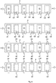
- the production apparatus 1 may comprise, in particular, means for feeding a first separator 2 and a second separator 3 that are next to one another along a (preset) advancement path.
- the first separator 2 may comprise a separator material in the form of a continuous tape.
- the second separator 3 may comprise a separator material in the form of a continuous tape.
- the means for feeding the first and the second separators 2 and 3 may comprise, in particular, at least one first feeder 4 arranged for feeding the first tape-shaped separator 2.
- the means for feeding the first and the second separators may comprise, in particular, at least one second feeder 5 arranged for feeding the second tape-shaped separator 3.
- the first feeder 4 may comprise, for example, a (known) device for unwinding at least one tape from at least one reel.
- the second feeder 5 may comprise, for example, a (known) device for unwinding at least one tape from at least one reel.
- the first feeder 4 may operate, in particular, with continuous and/or intermittent advancement.
- the second feeder 5 may operate, in particular, with continuous and/or intermittent advancement.
- the production apparatus 1 may comprise, in particular, means for arranging a succession of first electrodes A1, A2 one after another on the aforesaid advancement path between the first separator 2 and the second separator 3.
- the aforesaid means for arranging a succession of first electrodes A1, A2 may comprise, in particular, at least one third feeder 6 arranged for feeding a succession of first electrodes A1 in an inlet zone between the two separators 2 and 3 and at least one fourth feeder 7 arranged for feeding a succession of first electrodes A2 in the aforesaid inlet zone.
- the third feeder 6 and the fourth feeder 7 may be configured, in particular, in such a manner as to feed the first electrodes A1, A2 alternately one before the other, in succession.
- the third feeder 6 may comprise, for example, a (known) device for unwinding at least one tape from at least one reel.
- the fourth feeder 7 may comprise, for example, a (known) device for unwinding at least one tape from at least one reel.
- the third feeder 6 may operate, in particular, with continuous and/or intermittent advancement.
- the fourth feeder 7 may operate, in particular, with continuous and/or intermittent advancement.
- the third feeder 6 may comprise, for example, a (known) device for separating electrodes A1 from a tape and for applying electrodes A1 to a separator.
- the fourth feeder 7 may comprise, for example, a (known) device for separating electrodes A2 from a tape and for applying electrodes A2 to a separator.
- the production apparatus 1 may comprise, in particular, means for arranging a succession of second electrodes C1 one after another on the aforesaid advancement path on a side of the first separator 2 opposite the second separator 3.
- the aforesaid means for arranging a succession of second electrodes C1 may comprise, in particular, at least one fifth feeder 8 arranged for feeding second electrodes C1 on a side of the first separator 2.
- the fifth feeder 8 may comprise, for example, a (known) device for unwinding at least one tape from at least one reel.
- the fifth feeder 8 may operate, in particular, with continuous and/or intermittent advancement.
- the fifth feeder 8 may comprise, for example, a (known) device for separating electrodes C1 from a tape and for applying electrodes C1 to a separator.
- the production apparatus 1 may comprise, in particular, means for arranging a succession of third electrodes C2 one after another on the aforesaid advancement path on a side of the second separator 3 opposite the first separator 2.
- the aforesaid means for arranging a succession of third electrodes C2 may comprise, in particular, at least one sixth feeder 9 arranged for feeding third electrodes C2 on a side of the second separator 3.
- the sixth feeder 9 may comprise, for example, a (known) device for unwinding at least one tape from at least one reel.
- the sixth feeder 9 may operate, in particular, with continuous and/or intermittent advancement.
- the sixth feeder 9 may comprise, for example, a (known) device for separating electrodes C2 from a tape and for applying electrodes C2 to a separator.
- the production apparatus 1 may comprise, in particular, control means configured for controlling the aforesaid feeding means for feeding the separators and the electrodes such that the second electrodes C1 are superimposed on respective first electrodes A1 with the interposition of the first separator 2.
- the control means may comprise programmable electronic control means, for example an electronic processor, provided with computer programme instructions that are implementable on the control means.
- the control means may be configured, in particular, for controlling the aforesaid feeding means for feeding the separators and the electrodes in such a manner that on some portions of the first separator 2 second electrodes C1 are not arranged (in a regular manner).
- the aforesaid portions of the first separator 2, on which the second electrodes C1 are not arranged, may be superimposed on one or more first electrodes A2.
- the control means may be configured, in particular, for controlling the aforesaid feeding means for feeding the separators and the electrodes such that the third electrodes C2 are superimposed on respective first electrodes A2 with the interposition of the second separator 3.
- the control means may be configured, in particular, for controlling the aforesaid feeding means for feeding the separators and the electrodes in such a manner that on some portions of the second separator 3 third electrodes C2 are not arranged.
- the aforesaid portions of the second separator 3, on which third electrodes C2 are not arranged, may be superimposed on one or more first electrodes A1.
- the control means may be configured, in particular, for controlling the aforesaid feeding means for feeding the separators and the electrodes such that the second electrodes C1 are superimposed on first electrodes A1 that may be in turn superimposed on portions of second separator 3 on which third electrodes C2 are not arranged.
- the control means may be configured, in particular, for controlling the aforesaid feeding means for feeding the separators and the electrodes such that the third electrodes C2 are superimposed on first electrodes A2 that may be in turn superimposed on portions of first separator 2 on which second electrodes C1 are not arranged.
- the production apparatus 1 may comprise, in particular, at least one laminating device 10 (for example of the roller type) arranged along the aforesaid advancement path for coupling, by lamination, the separators 2 and 3 with at least the first electrodes A1, A2 and/or the second electrodes C1 and/or the third electrodes C2.
- the laminating device 10 may be arranged, in particular, downstream of the zones in which the various feeders 6-9 introduce the electrodes A1, A2, C1, C2 onto the separators 2 and 3.
- the production apparatus 1 may comprise, in particular, at least one cutting device 11 arranged for separating (for example by laser cutting, twin-bladed mechanical cutting, or other types of cutting) discrete elements from a continuous product.
- the cutting device 11 may be arranged, in particular, downstream of the zones in which the various feeders 6-9 introduce the electrodes A1, A2, C1, and C2 onto the separators 2 and 3 and/or downstream of the laminating device 10.
- the control means may be configured in such a manner as to actuate a method for the production of electrical energy storage devices.
- This method of production may comprise, in particular, the step of feeding the first separator 2 and the second separator 3 that are next to one another along the advancement path.
- This method of production may comprise, in particular, the step of arranging a succession of first electrodes A1, A2 one after another in the advancement path between the first separator 2 and the second separator 3.
- the first electrodes A1, A2 may be arranged so as to alternate a first electrode A1 coming from the third feeder 6 with a first electrode A2 coming from the fourth feeder 7.
- This method of production may comprise, in particular, the step of arranging a succession of second electrodes C1 one after another in the advancement path on the (outer) side of the first separator 2 opposite the second separator 3.
- Each second electrode C1 may be superimposed on a respective first electrode A1 with the interposition of the first separator 2.
- Such portions of first separator 2 may be superimposed on at least one first electrode A1.
- This method of production may comprise, in particular, the step of arranging a succession of third electrodes C2 one after another in the advancement path on the (outer) side of the second separator 3 opposite the first separator 2.
- Each third electrode C2 may be superimposed on a respective first electrode A2 with the interposition of the second separator 3.
- Such portions of second separator 3 may be superimposed on at least one first electrode A2.
- the second electrodes C1 and the third electrodes C2 may be arranged so as to alternate a second electrode C1 (on the outer side of the first separator 2) coming from the fifth feeder 8 with one third electrode C2 (on the outer side of the second separator 3) coming from the sixth feeder 9.
- the second electrodes C1 and the third electrodes C2 may be arranged so as to superimpose a second electrode C1 (coming from the fifth feeder 8) on a first electrode A1 (coming from the third feeder 6) and a third electrode C2 (coming from the sixth feeder 9) on a first electrode A2 (coming from the fourth feeder 7).
- the first electrodes A1 and A2 may comprise, in particular, anodes.
- the second electrodes C1 may comprise, in particular, cathodes.
- the third electrodes C2 may comprise, in particular, cathodes.
- the method of production may provide, in particular, for each second electrode C1 being superimposed on a respective first electrode A1 (by the third feeder 6) which in turn may be superimposed on a portion of second separator 3 on which no third electrode C2 is arranged.
- the method of production may provide, in particular, for each third electrode C2 being superimposed on a respective first electrode A2 (by the fourth feeder 7) which in turn is superimposed on a portion of first separator 2 on which no second electrode C1 is arranged.
- the first separator 2 may comprise a continuous (tape) element.
- the second separator 3 may comprise a continuous (tape) element.
- the method of production may comprise, in particular, the step of separating discrete elements K, J from a product that comprises the first, the second and the third electrodes A1, A2, C1, and C2 arranged on the first and on the second separators 2 and 3. Separation may be performed by a cutting device (for example by the cutting device 11).
- Each discrete element K, J that is separated may comprise, as in this embodiment, just one first electrode A1 or A2 and only one other electrode that may consist of a second electrode C1 or a third electrode C2.
- the method may comprise, in particular, the step of forming at least one first group 12 that comprises a plurality of discrete elements K that are coupled with one another (for example serially connected), in which the other electrode of the discrete elements K of the first group 12 is a second electrode C1.
- the first group 12 may comprise, for example, a (vertical) stack of discrete elements K superimposed on one another.
- the method may comprise, in particular, the step of forming at least one second group 13 that comprises a plurality of discrete elements J that are coupled with one another (for example serially connected), in which the other electrode of the discrete elements J of the second group 13 is a third electrode C2.
- the second group 13 may comprise, for example, a (vertical) stack of discrete elements J superimposed on one another.
- the method may comprise, in particular, the step of separating discrete auxiliary elements H from a product comprising the first electrodes A1, A2 arranged between the first separator 2 and the second separator 3, without the second and the third electrodes C1 and C2.
- Each discrete auxiliary element H may comprise, as in this case, just one first electrode A1 or A2 comprised between the separators 2 and 3, without any other electrode.
- One discrete auxiliary element H may be located at the top of the first group 12 (vertical stack) and at the base of the second group 13 (vertical stack) in such a manner that the end electrodes located at the base and at the top of the first group 12 consist of first electrodes A1 and that the end electrodes located at the base and at the top of the second group 13 consist of first electrodes A2. In this manner it is possible to ensure that the end electrodes are always of the same type (anodes), without the need to overturn a discrete element K or J.
- the method of production may comprise, in particular, the step of forming at least one first magazine 14 of discrete auxiliary elements H.
- the step of forming the first magazine 14 may comprise the step of feeding the separators 2 and 3 and the first electrodes A1 and A2 along the aforesaid advancement path, without feeding, for a certain period of time, the second and third electrodes C1 and C2.
- the step of forming the first magazine 14 may comprise the step of coupling (by the laminating device 10) the separators 2 and 3 with the first electrodes A1 and A2, the step of separating discrete auxiliary elements H (by the cutting device 11) and the step of conveying the discrete auxiliary elements H to the first magazine 14.
- the discrete auxiliary elements H may be withdrawn from the first magazine 14 according to need.
- the method of production may comprise, in particular, the step of forming at least one second magazine 15 of discrete elements K in which the other electrode of these discrete elements K consists of a second electrode C1.
- the method of production may comprise, in particular, the step of forming at least one third magazine 16 of discrete elements J in which the other electrode of these discrete elements J consists of one third electrode C2.
- the discrete elements K and J may be withdrawn from the second magazine 15 or from the third magazine 16 according to need, in particular to replace possible defects of discrete elements K or J during the normal processing process, for example because of rejects due to defects of an element or because of other process irregularities.
- the method of production may comprise, in particular, the step of coupling, by lamination (for example by the laminating device 10), the first, the second and the third electrodes A1, A2, C1, C2 with the first and the second separator 2 and 3.
- the groups 12 and 13 of discrete elements may undergo further processes (of known type) in order to obtain the final product, i.e. electrical energy storage devices, in particular lithium ion batteries.
- the various feeders 4-9 may comprise, in particular, devices for feeding separators and/or electrodes of the type already in use in known apparatuses for the production of electrical energy storage devices.
- the production apparatus 1 may further comprise one or more manipulators (not shown, for example of known type) configured in such a manner as to transfer the discrete elements K and J and the discrete auxiliary elements H from the outlet of the cutting device 11 to the desired places, in particular to the grouping zones, i.e. where the groups 12 and 13 are formed, or to the magazines 14, 15 and 16, or from the magazines 14, 15 and 16 to the formation zones of the groups 12 and 13.
- manipulators not shown, for example of known type
- the discrete auxiliary element H could be positioned at the end of the group 12 (at the top of the stack) in a place that is different from the forming pace of the group 12, for example in a work station into which the group 12 is transferred to enable the next group 12 to be formed.
Landscapes
- Chemical & Material Sciences (AREA)
- Chemical Kinetics & Catalysis (AREA)
- Electrochemistry (AREA)
- General Chemical & Material Sciences (AREA)
- Engineering & Computer Science (AREA)
- Manufacturing & Machinery (AREA)
- Secondary Cells (AREA)
- Separation By Low-Temperature Treatments (AREA)
- Electric Double-Layer Capacitors Or The Like (AREA)
Claims (15)
- Verfahren zur Herstellung von elektrischen Energiespeichervorrichtungen, wobei das Verfahren die folgenden Schritte aufweist:- Zuführen eines ersten Separators (2) und eines zweiten Separators (3);- Anordnen einer Abfolge von ersten Elektroden (A1, A2) nacheinander zwischen dem ersten und dem zweiten Separator (2; 3);- Anordnen einer Abfolge von zweiten Elektroden (C1) nacheinander auf einer dem zweiten Separator (3) gegenüberliegenden Seite des ersten Separators (2), wobei die zweiten Elektroden (C1) jeweiligen ersten Elektroden (Al) unter Zwischenfügung des ersten Separators (2) überlagert sind, wobei zweite Elektroden (C1) in einigen Bereichen des ersten Separators (2) nicht angeordnet sind, die mit einer oder mehreren ersten Elektroden (A2) überlappen;- Anordnen einer Abfolge von dritten Elektroden (C2) nacheinander auf einer dem ersten Separator (2) gegenüberliegenden Seite des zweiten Separators (3), wobei die dritten Elektroden (C2) jeweiligen ersten Elektroden (A2) unter Zwischenfügung des zweiten Separators (3) überlagert sind, wobei dritte Elektroden (C2) in einigen Bereichen des zweiten Separators (3) nicht angeordnet sind, die einer oder mehreren ersten Elektroden (A1) überlagert sind;wobei die zweiten Elektroden (C1) ersten Elektroden (Al) überlagert sind, die wiederum Bereichen des zweiten Separators (3) überlagert sind, in welchen dritte Elektroden (C2) nicht angeordnet sind, wobei die dritten Elektroden (C2) ersten Elektroden (A2) überlagert sind, welche wiederum Bereichen des ersten Separators (2) überlagert sind, in welchen keine zweiten Elektroden (CI) angeordnet sind;
wobei der erste und der zweite Separator (2; 3) zwei durchgehende Elemente aufweisen, wobei das Verfahren den Schritt des Trennens diskreter Elemente (K, J) von einem Produkt aufweist, das die ersten, zweiten und dritten Elektroden (A1, A2, C1, C2) und den ersten und den zweiten Separator (2; 3) aufweist, wobei jedes diskrete Element (K; J) nur eine erste Elektrode (A1, A2) zwischen den Separatoren (2; 3) und nur eine andere Elektrode aufweist, die aus einer zweiten Elektrode (C1) oder einer dritten Elektrode (C2) gebildet ist. - Verfahren nach Anspruch 1, mit dem Schritt des Bildens mindestens einer ersten Gruppe (12), die mehrere miteinander gekoppelte diskrete Elemente (K) aufweist, und mit dem Schritt des Bildens mindestens einer zweiten Gruppe (13), die mehrere miteinander gekoppelte diskrete Elemente (J) aufweist; wobei die andere Elektrode der diskreten Elemente (K) der ersten Gruppe (12) eine zweite Elektrode (C1) ist und/oder die andere Elektrode der diskreten Elemente (J) der zweiten Gruppe (13) eine dritte Elektrode (C2) ist.
- Verfahren nach Anspruch 2, mit dem Schritt des Trennens diskreter Hilfselemente (H) von einem Produkt, welches die ersten Elektroden (A1, A2), die auf dem ersten und zweiten Separator (2; 3) ohne die zweiten und dritten Elektroden (C1; C2) angeordnet sind, wobei jedes diskrete Hilfselement nur eine erste Elektrode (A1, A2) zwischen den Separatoren (2; 3) ohne eine andere Elektrode aufweist; wobei optional ein diskretes Hilfselement (H) an einem Ende der ersten Gruppe (12) und an einem Ende der zweiten Gruppe (13) angeordnet ist, so dass die an den beiden gegenüberliegenden Enden jeder Gruppe angeordneten Elektroden, das heißt sowohl der ersten Gruppe (12) als auch der zweiten Gruppe (13), aus ersten Elektroden (A1, A2) bestehen.
- Verfahren nach Anspruch 3, mit dem Schritt des Bildens mindestens eines ersten Magazins (14) von diskreten Hilfselementen (H).
- Verfahren nach einem der vorhergehenden Ansprüche, mit dem Schritt des Bildens mindestens eines zweiten Magazins (15) von diskreten Hilfselementen (K), wobei die andere Elektrode eine zweite Elektrode (C1) ist, und mindestens eines dritten Magazins (16) von diskreten Elementen (J), in denen die andere Elektrode eine dritte Elektrode (C2) ist.
- Verfahren nach einem der vorhergehenden Ansprüche, wobei die ersten Elektroden (A1, A2) Anoden aufweisen und/oder wobei die zweiten Elektroden (C1) Kathoden aufweisen und/oder wobei die dritte Elektrode (C2) Kathoden aufweist.
- Verfahren nach einem der vorhergehenden Ansprüche, mit dem Schritt des Koppelns der ersten, zweiten und dritten Elektroden (A1, A2, C1, C2) mit dem ersten und dem zweiten Separator (2; 3) durch Laminieren.
- Verfahren zur Herstellung von elektrischen Energiespeichervorrichtungen, insbesondere nach einem der vorhergehenden Ansprüche, wobei das Verfahren die folgenden Schritte aufweist:- Zuführen eines ersten Separators (2) und eines zweiten Separators (3), die nebeneinander entlang eines Vorschubwegs angeordnet sind;- Anordnen einer Abfolge von ersten Elektroden (A1, A2) nacheinander in dem Vorschubweg zwischen dem ersten und dem zweiten Separator (2; 3);- Anordnen einer Abfolge von zweiten Elektroden (C1) nacheinander in dem Vorschubweg auf einer dem zweiten Separator (3) gegenüberliegenden Seite des ersten Separators (2), wobei die zweiten Elektroden (C1) jeweiligen ersten Elektroden (A1) unter Zwischenfügung des ersten Separators (2) überlagert sind, wobei zweite Elektroden (CI) nicht in einigen Bereichen des ersten Separators (2) angeordnet sind, die mit einer oder mehreren ersten Elektroden (A2) überlappen;- Anordnen einer Folge von dritten Elektroden (C2) nacheinander in dem Vorschubweg auf einer dem ersten Separator (2) gegenüberliegenden Seite des zweiten Separators (3), wobei die dritten Elektroden (C2) jeweiligen ersten Elektroden (A2) unter Zwischenfügung des zweiten Separators (3) überlagert sind, wobei die dritten Elektroden (C2) nicht in einigen Bereichen des zweiten Separators (3) angeordnet, die einer oder mehreren ersten Elektroden (Al) überlagert sind;wobei die zweiten Elektroden (C1) den ersten Elektroden (A1) überlagert sind, die wiederum Bereiche des zweiten Separators (3) überlagern, in denen die dritten Elektroden (C2) nicht angeordnet sind, wobei die dritten Elektroden (C2) den ersten Elektroden überlagert sind (A2), die wiederum Bereiche des ersten Separators (2) überlagern, in denen keine zweiten Elektroden (C1) angeordnet sind.
- Vorrichtung zur Herstellung von elektrischen Energiespeichervorrichtungen, insbesondere zum Implementieren eines Verfahrens nach einem der vorhergehenden Ansprüche, wobei die Vorrichtung aufweist:- Einrichtungen (4; 5) zum Zuführen eines ersten Separators (2) und eines zweiten Separators (3), die nebeneinander entlang eines Vorschubweges angeordnet sind;- Einrichtungen (6; 7) zum Anordnen einer Abfolge erster Elektroden (Al, A2) nacheinander, die zwischen dem ersten Separator (2) und dem zweiten Separator (3) entlang des Vorschubwegs angeordnet sind;- Einrichtungen (8) zum Anordnen einer Abfolge zweiter Elektroden (C1) nacheinander auf einer dem zweiten Separator (3) gegenüberliegenden Seite des ersten Separators (2) entlang des Vorschubweges;- Einrichtungen (9) zum Anordnen einer Abfolge dritter Elektroden (C2) nacheinander auf einer dem ersten Separator (2) gegenüberliegenden Seite des zweiten Separators (3) entlang des Vorschubweges;- Steuereinrichtungen, die dazu konfiguriert sind, die Vorrichtung derart zu steuern, dass:* die zweiten Elektroden (C1) unter Zwischenfügung des ersten Separators (2) mit jeweiligen ersten Elektroden (Al) überlappen;* zweite Elektroden (CI) nicht in einigen Bereichen des ersten Separators (2) angeordnet sind, wobei diese Bereiche des ersten Separators (2) einer oder mehreren ersten Elektroden (A2) überlagert sind;* die dritten Elektroden (C2) jeweiligen ersten Elektroden (A2) unter Zwischenfügung des zweiten Separators (3) überlagert sind;* dritte Elektroden (C2) nicht in einigen Bereichen des zweiten Separators (3) angeordnet sind, wobei diese Bereiche des zweiten Separators (3) einer oder mehreren ersten Elektroden (Al) überlagert sind;* die zweiten Elektroden (C1) den ersten Elektroden (A1) überlagert sind, die wiederum Bereiche des zweiten Separators (3) überlagern, in denen die dritten Elektroden (C2) nicht angeordnet sind;* die dritten Elektroden (C2) den ersten Elektroden (A2) überlagert sind, die wiederum Bereiche des ersten Separators (2) überlagern, in denen die zweiten Elektroden (C1) nicht angeordnet sind.
- Vorrichtung nach Anspruch 9, bei welcher die Steuereinrichtung derart konfiguriert ist, dass sie diskrete Elemente (K, J) von einem Produkt trennt, das die ersten, zweiten und dritten Elektroden (A1, A2, C1, C2) und den ersten und zweiten Separator (2; 3) aufweist, wobei jedes diskrete Element (K; J) nur eine erste Elektrode (Al, A2) zwischen den Separatoren (2; 3) und nur eine andere Elektrode aufweist, die aus einer zweiten Elektrode (C1) oder einer dritten Elektrode besteht (C2).
- Vorrichtung nach Anspruch 10, bei welcher die Steuereinrichtung derart konfiguriert ist, dass sie mindestens eine erste Gruppe (12) mit mehreren diskreten Elementen (K) und mindestens eine zweite Gruppe (13) mit mehreren diskreten Elementen (J) bildet, wobei die andere Elektrode der diskreten Elemente (K) der ersten Gruppe (12) eine zweite Elektrode (C1) ist und/oder die andere Elektrode der diskreten Elemente (J) der zweiten Gruppe (13) eine dritte Elektrode (C2) ist.
- Vorrichtung nach Anspruch 10 oder 11, bei welcher die Steuereinrichtung derart konfiguriert ist, dass sie diskrete Hilfselemente (H) von einem Produkt trennt, das die ersten Elektroden (A1, A2) aufweist, die auf dem ersten und dem zweiten Separator (2; 3) ohne die zweite und dritte Elektrode (C1, C2) angeordnet sind, wobei jedes diskrete Hilfselement nur eine erste Elektrode (A1, A2) zwischen den Separatoren (2; 3) ohne eine andere Elektrode aufweist.
- Vorrichtung nach den Ansprüchen 12 und 11, bei welcher die Steuereinrichtung derart konfiguriert ist, dass sie ein diskretes Hilfselement (H) an einem Ende der ersten Gruppe (12) und an einem Ende der zweiten Gruppe (13) derart anordnet, dass die Elektroden an den beiden gegenüberliegenden Enden jeder Gruppe, d.h. sowohl die erste Gruppe (12), als auch die zweite Gruppe (13), aus ersten Elektroden (A1, A2) gebildet sind.
- Vorrichtung nach einem der Ansprüche 9 bis 13, wobei die Einrichtung zum Zuführen eines ersten und eines zweiten Separators mindestens eine erste Zuführeinrichtung (4) aufweist, die zum Zuführen des ersten Separators (2) in Form eines Bandes vorgesehen ist, und mindestens eine zweite Zuführeinrichtung (5) aufweist, die zum Zuführen des zweiten Separators (3) in Form eines Bandes vorgesehen ist.
- Vorrichtung nach einem der Ansprüche 9 bis 14, bei welcher die Einrichtung zum Anordnen einer Abfolge erster Elektroden mindestens eine dritte Zuführeinrichtung (6) aufweist, die zum Zuführen einiger erster Elektroden (A1) in einen Einlassbereich vorgesehen ist, und mindestens eine vierte Zuführeinrichtung (7) aufweist, die zum Zuführen einiger anderer erster Elektroden (A2) in den Einlassbereich vorgesehen ist, wobei die dritte und vierte Zuführeinrichtung (6; 7) derart konfiguriert sind, dass sie die ersten Elektroden (A1, A2) abwechselnd aus der einen und der anderen zuführen; und/oder wobei die Einrichtung zum Anordnen einer Abfolge zweiter Elektroden mindestens eine fünfte Zuführeinrichtung (8) aufweist, die zum Zuführen der zweiten Elektroden (C1) auf einer Seite des ersten Separators (2) vorgesehen ist, und/oder wobei die Einrichtung zum Anordnen einer Abfolge dritter Elektroden mindestens eine sechste Zuführeinrichtung (9) aufweist, die zum Zuführen der dritten Elektroden (C2) auf einer Seite des zweiten Separators (3) vorgesehen ist, und/oder wobei die Steuermittel programmierbare elektronische Einrichtungen aufweisen.
Priority Applications (1)
| Application Number | Priority Date | Filing Date | Title |
|---|---|---|---|
| PL17808178T PL3520164T3 (pl) | 2016-11-24 | 2017-11-20 | Wytwarzanie urządzeń do magazynowania energii elektrycznej |
Applications Claiming Priority (2)
| Application Number | Priority Date | Filing Date | Title |
|---|---|---|---|
| IT102016000119013A IT201600119013A1 (it) | 2016-11-24 | 2016-11-24 | Produzione di Dispositivi di Accumulo di Energia Elettrica |
| PCT/IB2017/057244 WO2018096435A1 (en) | 2016-11-24 | 2017-11-20 | Production of electrical energy storage devices |
Publications (2)
| Publication Number | Publication Date |
|---|---|
| EP3520164A1 EP3520164A1 (de) | 2019-08-07 |
| EP3520164B1 true EP3520164B1 (de) | 2020-07-15 |
Family
ID=58401971
Family Applications (1)
| Application Number | Title | Priority Date | Filing Date |
|---|---|---|---|
| EP17808178.2A Active EP3520164B1 (de) | 2016-11-24 | 2017-11-20 | Herstellung von energiespeichervorrichtungen |
Country Status (9)
| Country | Link |
|---|---|
| US (1) | US11081719B2 (de) |
| EP (1) | EP3520164B1 (de) |
| JP (1) | JP6972130B2 (de) |
| KR (1) | KR102226664B1 (de) |
| CN (1) | CN109565068B (de) |
| HU (1) | HUE051291T2 (de) |
| IT (1) | IT201600119013A1 (de) |
| PL (1) | PL3520164T3 (de) |
| WO (1) | WO2018096435A1 (de) |
Families Citing this family (12)
| Publication number | Priority date | Publication date | Assignee | Title |
|---|---|---|---|---|
| IT201900003489A1 (it) | 2019-03-11 | 2020-09-11 | Manz Italy Srl | Metodo e apparato di assemblaggio celle |
| CN112310458A (zh) * | 2019-07-31 | 2021-02-02 | 广东利元亨智能装备股份有限公司 | 叠片机 |
| CN110459796B (zh) * | 2019-08-16 | 2023-06-13 | 宁德时代新能源科技股份有限公司 | 一种叠片电芯的制备方法、叠片电芯、叠片装置及系统 |
| WO2022016194A1 (en) * | 2020-07-16 | 2022-01-20 | Battelle Energy Alliance, Llc | Methods for operating energy storage devices with sulfur‑based cathodes, and related systems and methods |
| DE102020124040A1 (de) * | 2020-09-15 | 2022-03-17 | Volkswagen Aktiengesellschaft | Verfahren und Vorrichtung zur Herstellung eines Zellstapels für Batteriezellen |
| DE102020124039A1 (de) | 2020-09-15 | 2022-03-17 | Volkswagen Aktiengesellschaft | Verfahren und Vorrichtung zur Herstellung eines Zellstapels für Batteriezellen |
| DE102020124038A1 (de) | 2020-09-15 | 2022-03-17 | Volkswagen Aktiengesellschaft | Verfahren und Vorrichtung zur Herstellung eines Zellstapels für Batteriezellen |
| KR102885404B1 (ko) * | 2021-02-05 | 2025-11-13 | 주식회사 엘지에너지솔루션 | 가압력 조절이 가능한 라미네이션 롤을 포함하는 라미네이션 장치 및 이를 이용하여 제조된 전극조립체 |
| KR102378979B1 (ko) * | 2021-07-26 | 2022-03-25 | (주)미디어테크 | 리튬메탈 배터리용 인라인 제조장치 |
| IT202100030254A1 (it) * | 2021-11-30 | 2023-05-30 | P I T S R L | Apparecchiatura per la formazione di un nastro di elettrodi per dispositivi di accumulo di energia elettrica |
| WO2023100210A1 (en) * | 2021-11-30 | 2023-06-08 | P.I.T. S.R.L. | Apparatus for forming an electrode strip for electrical energy storage devices |
| IT202100030281A1 (it) * | 2021-11-30 | 2023-05-30 | P I T S R L | Apparecchiatura per la formazione di un nastro di elettrodi per dispositivi di accumulo di energia elettrica |
Family Cites Families (17)
| Publication number | Priority date | Publication date | Assignee | Title |
|---|---|---|---|---|
| US20020007552A1 (en) | 1999-05-25 | 2002-01-24 | Singleton Robert W. | Apparatus and method of manufacturing a battery cell |
| KR100388648B1 (ko) | 2001-05-23 | 2003-06-25 | 주식회사 코캄엔지니어링 | 자동화된 리튬 2차전지 제조 시스템 |
| KR101209010B1 (ko) * | 2007-04-26 | 2012-12-06 | 주식회사 엘지화학 | 스택형 전극조립체 및 이의 제조방법 |
| JP5157244B2 (ja) | 2007-05-11 | 2013-03-06 | Tdk株式会社 | 電気化学デバイス及びその製造方法 |
| US20100304198A1 (en) * | 2009-05-28 | 2010-12-02 | Samsung Sdi Co., Ltd. | Electrode assembly for secondary battery and method of manufacturing the same |
| JP2011181395A (ja) * | 2010-03-02 | 2011-09-15 | Nippon Jido Seiki Kk | 積層型リチウムイオン二次電池及びその製造方法と製造装置 |
| EP2557626B1 (de) | 2010-04-06 | 2015-02-25 | LG Chem, Ltd. | Stapelzelle, erweiterte bizelle, elektrodenanordnung für eine sekundärbatterie damit und herstellungsverfahren dafür |
| DE102010055402A1 (de) | 2010-12-21 | 2012-06-21 | Li-Tec Battery Gmbh | Verfahren und System zur Herstellung elektrischer Zellen für elektrochemische Energiespeichervorrichtungen |
| JP2012185976A (ja) * | 2011-03-04 | 2012-09-27 | Ihi Corp | 積層型電池 |
| JP5291811B2 (ja) * | 2012-01-11 | 2013-09-18 | 東レエンジニアリング株式会社 | 2次電池の製造方法および製造装置 |
| EP2747186B1 (de) | 2012-02-28 | 2016-07-13 | Nagano Automation Co., Ltd. | Vorrichtung und verfahren zur herstellung eines elektrodenkörpers |
| WO2013176500A1 (ko) * | 2012-05-23 | 2013-11-28 | 주식회사 엘지화학 | 전극조립체 및 이를 포함하는 전기화학소자 |
| ITPD20120167A1 (it) | 2012-05-24 | 2013-11-25 | Sovema Spa | Macchina e procedimento per la realizzazione di celle per accumulatori elettrici e cella per accumulatore elettrico |
| KR101637659B1 (ko) * | 2013-06-28 | 2016-07-07 | 주식회사 엘지화학 | 세퍼레이터 절단공정을 포함하는 전극조립체의 제조방법 |
| KR101609425B1 (ko) * | 2013-09-26 | 2016-04-05 | 주식회사 엘지화학 | 매거진을 이용한 전극조립체의 제조방법 |
| KR101684590B1 (ko) * | 2013-10-31 | 2016-12-08 | 주식회사 엘지화학 | 전극 조립체 |
| KR102273780B1 (ko) * | 2014-07-04 | 2021-07-06 | 삼성에스디아이 주식회사 | 이차 전지, 이차 전지의 제조 장치 및 이차 전지의 제조 방법 |
-
2016
- 2016-11-24 IT IT102016000119013A patent/IT201600119013A1/it unknown
-
2017
- 2017-11-20 US US16/349,878 patent/US11081719B2/en not_active Expired - Fee Related
- 2017-11-20 HU HUE17808178A patent/HUE051291T2/hu unknown
- 2017-11-20 WO PCT/IB2017/057244 patent/WO2018096435A1/en not_active Ceased
- 2017-11-20 KR KR1020197001008A patent/KR102226664B1/ko not_active Expired - Fee Related
- 2017-11-20 CN CN201780044887.6A patent/CN109565068B/zh not_active Expired - Fee Related
- 2017-11-20 PL PL17808178T patent/PL3520164T3/pl unknown
- 2017-11-20 EP EP17808178.2A patent/EP3520164B1/de active Active
- 2017-11-20 JP JP2019527854A patent/JP6972130B2/ja not_active Expired - Fee Related
Non-Patent Citations (1)
| Title |
|---|
| None * |
Also Published As
| Publication number | Publication date |
|---|---|
| KR102226664B1 (ko) | 2021-03-12 |
| HUE051291T2 (hu) | 2021-03-01 |
| IT201600119013A1 (it) | 2018-05-24 |
| CN109565068A (zh) | 2019-04-02 |
| JP6972130B2 (ja) | 2021-11-24 |
| US11081719B2 (en) | 2021-08-03 |
| US20190273279A1 (en) | 2019-09-05 |
| PL3520164T3 (pl) | 2021-01-25 |
| CN109565068B (zh) | 2022-02-22 |
| EP3520164A1 (de) | 2019-08-07 |
| JP2020500407A (ja) | 2020-01-09 |
| WO2018096435A1 (en) | 2018-05-31 |
| KR20190031232A (ko) | 2019-03-25 |
Similar Documents
| Publication | Publication Date | Title |
|---|---|---|
| EP3520164B1 (de) | Herstellung von energiespeichervorrichtungen | |
| US9083007B2 (en) | Continuous prismatic cell stacking system and method | |
| KR101349205B1 (ko) | 이차 전지 다중 삽입 적층 장치 및 방법 | |
| US12021198B2 (en) | Method and apparatus for assembling electrodes | |
| CN103298572B (zh) | 连续式方形电池叠片系统和方法 | |
| KR101291063B1 (ko) | 2차 전지 내부 셀 스택 적층 장치 및 방법 | |
| KR101255351B1 (ko) | 2차 전지 내부 셀 스택 적층 장치 및 방법 | |
| DE102017216213A1 (de) | Verfahren zur Herstellung eines Elektrodenstapels | |
| KR20140035646A (ko) | 2차 전지 내부 셀 스택 방법 및 이를 이용하여 제조되는 셀 스택 | |
| JP2011181395A (ja) | 積層型リチウムイオン二次電池及びその製造方法と製造装置 | |
| KR102067252B1 (ko) | 연료전지용 분리판의 제조 설비 및 제조 방법 | |
| WO2012144008A1 (ja) | 二次電池の製造方法及び製造装置 | |
| KR20120118759A (ko) | 2차 전지 내부 셀 스택 및 그 제조 방법 | |
| CN106575788A (zh) | 用于形成卷绕结构的方法和装置 | |
| KR102821228B1 (ko) | 단위셀의 제조방법 | |
| KR20150085733A (ko) | 이차전지 제조방법 및 이차전지 | |
| KR20190056846A (ko) | 스택-폴딩형 전극 조립체의 제조 방법 및 스택-폴딩형 전극 조립체 | |
| KR20240054791A (ko) | 공정성이 개선된 전극 조립체 제조 방법 및 이를 사용하여 제조된 전극 조립체 | |
| WO2025186659A1 (en) | Method for making electrochemical cells and apparatus for making electrochemical cells | |
| KR20250126068A (ko) | 축전지 제조 방법 및 축전지 제조를 위한 상응하는 적층 장치 | |
| KR20040079528A (ko) | 전지 극판 적층 장치 및 방법 | |
| JPH0419670B2 (de) | ||
| JPH0654685B2 (ja) | 蓄電池の極板群製造装置 |
Legal Events
| Date | Code | Title | Description |
|---|---|---|---|
| STAA | Information on the status of an ep patent application or granted ep patent |
Free format text: STATUS: UNKNOWN |
|
| STAA | Information on the status of an ep patent application or granted ep patent |
Free format text: STATUS: THE INTERNATIONAL PUBLICATION HAS BEEN MADE |
|
| PUAI | Public reference made under article 153(3) epc to a published international application that has entered the european phase |
Free format text: ORIGINAL CODE: 0009012 |
|
| STAA | Information on the status of an ep patent application or granted ep patent |
Free format text: STATUS: REQUEST FOR EXAMINATION WAS MADE |
|
| 17P | Request for examination filed |
Effective date: 20190329 |
|
| AK | Designated contracting states |
Kind code of ref document: A1 Designated state(s): AL AT BE BG CH CY CZ DE DK EE ES FI FR GB GR HR HU IE IS IT LI LT LU LV MC MK MT NL NO PL PT RO RS SE SI SK SM TR |
|
| AX | Request for extension of the european patent |
Extension state: BA ME |
|
| GRAP | Despatch of communication of intention to grant a patent |
Free format text: ORIGINAL CODE: EPIDOSNIGR1 |
|
| STAA | Information on the status of an ep patent application or granted ep patent |
Free format text: STATUS: GRANT OF PATENT IS INTENDED |
|
| DAV | Request for validation of the european patent (deleted) | ||
| DAX | Request for extension of the european patent (deleted) | ||
| INTG | Intention to grant announced |
Effective date: 20200212 |
|
| GRAS | Grant fee paid |
Free format text: ORIGINAL CODE: EPIDOSNIGR3 |
|
| GRAA | (expected) grant |
Free format text: ORIGINAL CODE: 0009210 |
|
| STAA | Information on the status of an ep patent application or granted ep patent |
Free format text: STATUS: THE PATENT HAS BEEN GRANTED |
|
| AK | Designated contracting states |
Kind code of ref document: B1 Designated state(s): AL AT BE BG CH CY CZ DE DK EE ES FI FR GB GR HR HU IE IS IT LI LT LU LV MC MK MT NL NO PL PT RO RS SE SI SK SM TR |
|
| REG | Reference to a national code |
Ref country code: CH Ref legal event code: EP Ref country code: GB Ref legal event code: FG4D |
|
| REG | Reference to a national code |
Ref country code: IE Ref legal event code: FG4D |
|
| REG | Reference to a national code |
Ref country code: DE Ref legal event code: R096 Ref document number: 602017019964 Country of ref document: DE |
|
| REG | Reference to a national code |
Ref country code: AT Ref legal event code: REF Ref document number: 1292002 Country of ref document: AT Kind code of ref document: T Effective date: 20200815 |
|
| REG | Reference to a national code |
Ref country code: SE Ref legal event code: TRGR |
|
| REG | Reference to a national code |
Ref country code: LT Ref legal event code: MG4D |
|
| REG | Reference to a national code |
Ref country code: AT Ref legal event code: MK05 Ref document number: 1292002 Country of ref document: AT Kind code of ref document: T Effective date: 20200715 |
|
| REG | Reference to a national code |
Ref country code: NL Ref legal event code: MP Effective date: 20200715 |
|
| PG25 | Lapsed in a contracting state [announced via postgrant information from national office to epo] |
Ref country code: NO Free format text: LAPSE BECAUSE OF FAILURE TO SUBMIT A TRANSLATION OF THE DESCRIPTION OR TO PAY THE FEE WITHIN THE PRESCRIBED TIME-LIMIT Effective date: 20201015 Ref country code: BG Free format text: LAPSE BECAUSE OF FAILURE TO SUBMIT A TRANSLATION OF THE DESCRIPTION OR TO PAY THE FEE WITHIN THE PRESCRIBED TIME-LIMIT Effective date: 20201015 Ref country code: ES Free format text: LAPSE BECAUSE OF FAILURE TO SUBMIT A TRANSLATION OF THE DESCRIPTION OR TO PAY THE FEE WITHIN THE PRESCRIBED TIME-LIMIT Effective date: 20200715 Ref country code: GR Free format text: LAPSE BECAUSE OF FAILURE TO SUBMIT A TRANSLATION OF THE DESCRIPTION OR TO PAY THE FEE WITHIN THE PRESCRIBED TIME-LIMIT Effective date: 20201016 Ref country code: HR Free format text: LAPSE BECAUSE OF FAILURE TO SUBMIT A TRANSLATION OF THE DESCRIPTION OR TO PAY THE FEE WITHIN THE PRESCRIBED TIME-LIMIT Effective date: 20200715 Ref country code: FI Free format text: LAPSE BECAUSE OF FAILURE TO SUBMIT A TRANSLATION OF THE DESCRIPTION OR TO PAY THE FEE WITHIN THE PRESCRIBED TIME-LIMIT Effective date: 20200715 Ref country code: LT Free format text: LAPSE BECAUSE OF FAILURE TO SUBMIT A TRANSLATION OF THE DESCRIPTION OR TO PAY THE FEE WITHIN THE PRESCRIBED TIME-LIMIT Effective date: 20200715 Ref country code: PT Free format text: LAPSE BECAUSE OF FAILURE TO SUBMIT A TRANSLATION OF THE DESCRIPTION OR TO PAY THE FEE WITHIN THE PRESCRIBED TIME-LIMIT Effective date: 20201116 Ref country code: AT Free format text: LAPSE BECAUSE OF FAILURE TO SUBMIT A TRANSLATION OF THE DESCRIPTION OR TO PAY THE FEE WITHIN THE PRESCRIBED TIME-LIMIT Effective date: 20200715 |
|
| PG25 | Lapsed in a contracting state [announced via postgrant information from national office to epo] |
Ref country code: RS Free format text: LAPSE BECAUSE OF FAILURE TO SUBMIT A TRANSLATION OF THE DESCRIPTION OR TO PAY THE FEE WITHIN THE PRESCRIBED TIME-LIMIT Effective date: 20200715 Ref country code: LV Free format text: LAPSE BECAUSE OF FAILURE TO SUBMIT A TRANSLATION OF THE DESCRIPTION OR TO PAY THE FEE WITHIN THE PRESCRIBED TIME-LIMIT Effective date: 20200715 Ref country code: IS Free format text: LAPSE BECAUSE OF FAILURE TO SUBMIT A TRANSLATION OF THE DESCRIPTION OR TO PAY THE FEE WITHIN THE PRESCRIBED TIME-LIMIT Effective date: 20201115 |
|
| REG | Reference to a national code |
Ref country code: HU Ref legal event code: AG4A Ref document number: E051291 Country of ref document: HU |
|
| PG25 | Lapsed in a contracting state [announced via postgrant information from national office to epo] |
Ref country code: NL Free format text: LAPSE BECAUSE OF FAILURE TO SUBMIT A TRANSLATION OF THE DESCRIPTION OR TO PAY THE FEE WITHIN THE PRESCRIBED TIME-LIMIT Effective date: 20200715 |
|
| REG | Reference to a national code |
Ref country code: DE Ref legal event code: R097 Ref document number: 602017019964 Country of ref document: DE |
|
| PG25 | Lapsed in a contracting state [announced via postgrant information from national office to epo] |
Ref country code: CZ Free format text: LAPSE BECAUSE OF FAILURE TO SUBMIT A TRANSLATION OF THE DESCRIPTION OR TO PAY THE FEE WITHIN THE PRESCRIBED TIME-LIMIT Effective date: 20200715 Ref country code: DK Free format text: LAPSE BECAUSE OF FAILURE TO SUBMIT A TRANSLATION OF THE DESCRIPTION OR TO PAY THE FEE WITHIN THE PRESCRIBED TIME-LIMIT Effective date: 20200715 Ref country code: RO Free format text: LAPSE BECAUSE OF FAILURE TO SUBMIT A TRANSLATION OF THE DESCRIPTION OR TO PAY THE FEE WITHIN THE PRESCRIBED TIME-LIMIT Effective date: 20200715 Ref country code: EE Free format text: LAPSE BECAUSE OF FAILURE TO SUBMIT A TRANSLATION OF THE DESCRIPTION OR TO PAY THE FEE WITHIN THE PRESCRIBED TIME-LIMIT Effective date: 20200715 Ref country code: SM Free format text: LAPSE BECAUSE OF FAILURE TO SUBMIT A TRANSLATION OF THE DESCRIPTION OR TO PAY THE FEE WITHIN THE PRESCRIBED TIME-LIMIT Effective date: 20200715 |
|
| PLBE | No opposition filed within time limit |
Free format text: ORIGINAL CODE: 0009261 |
|
| STAA | Information on the status of an ep patent application or granted ep patent |
Free format text: STATUS: NO OPPOSITION FILED WITHIN TIME LIMIT |
|
| PG25 | Lapsed in a contracting state [announced via postgrant information from national office to epo] |
Ref country code: AL Free format text: LAPSE BECAUSE OF FAILURE TO SUBMIT A TRANSLATION OF THE DESCRIPTION OR TO PAY THE FEE WITHIN THE PRESCRIBED TIME-LIMIT Effective date: 20200715 |
|
| 26N | No opposition filed |
Effective date: 20210416 |
|
| PG25 | Lapsed in a contracting state [announced via postgrant information from national office to epo] |
Ref country code: MC Free format text: LAPSE BECAUSE OF FAILURE TO SUBMIT A TRANSLATION OF THE DESCRIPTION OR TO PAY THE FEE WITHIN THE PRESCRIBED TIME-LIMIT Effective date: 20200715 Ref country code: SK Free format text: LAPSE BECAUSE OF FAILURE TO SUBMIT A TRANSLATION OF THE DESCRIPTION OR TO PAY THE FEE WITHIN THE PRESCRIBED TIME-LIMIT Effective date: 20200715 |
|
| REG | Reference to a national code |
Ref country code: CH Ref legal event code: PL |
|
| PG25 | Lapsed in a contracting state [announced via postgrant information from national office to epo] |
Ref country code: LU Free format text: LAPSE BECAUSE OF NON-PAYMENT OF DUE FEES Effective date: 20201120 |
|
| REG | Reference to a national code |
Ref country code: BE Ref legal event code: MM Effective date: 20201130 |
|
| PG25 | Lapsed in a contracting state [announced via postgrant information from national office to epo] |
Ref country code: CH Free format text: LAPSE BECAUSE OF NON-PAYMENT OF DUE FEES Effective date: 20201130 Ref country code: LI Free format text: LAPSE BECAUSE OF NON-PAYMENT OF DUE FEES Effective date: 20201130 Ref country code: SI Free format text: LAPSE BECAUSE OF FAILURE TO SUBMIT A TRANSLATION OF THE DESCRIPTION OR TO PAY THE FEE WITHIN THE PRESCRIBED TIME-LIMIT Effective date: 20200715 |
|
| PG25 | Lapsed in a contracting state [announced via postgrant information from national office to epo] |
Ref country code: IE Free format text: LAPSE BECAUSE OF NON-PAYMENT OF DUE FEES Effective date: 20201120 |
|
| PG25 | Lapsed in a contracting state [announced via postgrant information from national office to epo] |
Ref country code: TR Free format text: LAPSE BECAUSE OF FAILURE TO SUBMIT A TRANSLATION OF THE DESCRIPTION OR TO PAY THE FEE WITHIN THE PRESCRIBED TIME-LIMIT Effective date: 20200715 Ref country code: MT Free format text: LAPSE BECAUSE OF FAILURE TO SUBMIT A TRANSLATION OF THE DESCRIPTION OR TO PAY THE FEE WITHIN THE PRESCRIBED TIME-LIMIT Effective date: 20200715 Ref country code: CY Free format text: LAPSE BECAUSE OF FAILURE TO SUBMIT A TRANSLATION OF THE DESCRIPTION OR TO PAY THE FEE WITHIN THE PRESCRIBED TIME-LIMIT Effective date: 20200715 |
|
| PG25 | Lapsed in a contracting state [announced via postgrant information from national office to epo] |
Ref country code: MK Free format text: LAPSE BECAUSE OF FAILURE TO SUBMIT A TRANSLATION OF THE DESCRIPTION OR TO PAY THE FEE WITHIN THE PRESCRIBED TIME-LIMIT Effective date: 20200715 |
|
| GBPC | Gb: european patent ceased through non-payment of renewal fee |
Effective date: 20211120 |
|
| PG25 | Lapsed in a contracting state [announced via postgrant information from national office to epo] |
Ref country code: BE Free format text: LAPSE BECAUSE OF NON-PAYMENT OF DUE FEES Effective date: 20201130 |
|
| PG25 | Lapsed in a contracting state [announced via postgrant information from national office to epo] |
Ref country code: GB Free format text: LAPSE BECAUSE OF NON-PAYMENT OF DUE FEES Effective date: 20211120 |
|
| PGFP | Annual fee paid to national office [announced via postgrant information from national office to epo] |
Ref country code: SE Payment date: 20221123 Year of fee payment: 6 Ref country code: FR Payment date: 20221122 Year of fee payment: 6 |
|
| PGFP | Annual fee paid to national office [announced via postgrant information from national office to epo] |
Ref country code: HU Payment date: 20221102 Year of fee payment: 6 |
|
| P01 | Opt-out of the competence of the unified patent court (upc) registered |
Effective date: 20230530 |
|
| REG | Reference to a national code |
Ref country code: SE Ref legal event code: EUG |
|
| PG25 | Lapsed in a contracting state [announced via postgrant information from national office to epo] |
Ref country code: HU Free format text: LAPSE BECAUSE OF NON-PAYMENT OF DUE FEES Effective date: 20231121 Ref country code: SE Free format text: LAPSE BECAUSE OF NON-PAYMENT OF DUE FEES Effective date: 20231121 |
|
| PG25 | Lapsed in a contracting state [announced via postgrant information from national office to epo] |
Ref country code: FR Free format text: LAPSE BECAUSE OF NON-PAYMENT OF DUE FEES Effective date: 20231130 |
|
| PG25 | Lapsed in a contracting state [announced via postgrant information from national office to epo] |
Ref country code: FR Free format text: LAPSE BECAUSE OF NON-PAYMENT OF DUE FEES Effective date: 20231130 |
|
| PGFP | Annual fee paid to national office [announced via postgrant information from national office to epo] |
Ref country code: DE Payment date: 20241128 Year of fee payment: 8 |
|
| PGFP | Annual fee paid to national office [announced via postgrant information from national office to epo] |
Ref country code: PL Payment date: 20241104 Year of fee payment: 8 |
|
| PGFP | Annual fee paid to national office [announced via postgrant information from national office to epo] |
Ref country code: IT Payment date: 20241106 Year of fee payment: 8 |