EP3519841B1 - Wireless magnetic resonance energy harvesting and coil detuning - Google Patents
Wireless magnetic resonance energy harvesting and coil detuning Download PDFInfo
- Publication number
- EP3519841B1 EP3519841B1 EP17780359.0A EP17780359A EP3519841B1 EP 3519841 B1 EP3519841 B1 EP 3519841B1 EP 17780359 A EP17780359 A EP 17780359A EP 3519841 B1 EP3519841 B1 EP 3519841B1
- Authority
- EP
- European Patent Office
- Prior art keywords
- magnetic resonance
- energy
- circuit
- coil
- transmissions
- Prior art date
- Legal status (The legal status is an assumption and is not a legal conclusion. Google has not performed a legal analysis and makes no representation as to the accuracy of the status listed.)
- Active
Links
Images


Classifications
-
- G—PHYSICS
- G01—MEASURING; TESTING
- G01R—MEASURING ELECTRIC VARIABLES; MEASURING MAGNETIC VARIABLES
- G01R33/00—Arrangements or instruments for measuring magnetic variables
- G01R33/20—Arrangements or instruments for measuring magnetic variables involving magnetic resonance
- G01R33/28—Details of apparatus provided for in groups G01R33/44 - G01R33/64
- G01R33/32—Excitation or detection systems, e.g. using radio frequency signals
- G01R33/36—Electrical details, e.g. matching or coupling of the coil to the receiver
- G01R33/3642—Mutual coupling or decoupling of multiple coils, e.g. decoupling of a receive coil from a transmission coil, or intentional coupling of RF coils, e.g. for RF magnetic field amplification
- G01R33/3657—Decoupling of multiple RF coils wherein the multiple RF coils do not have the same function in MR, e.g. decoupling of a transmission coil from a receive coil
-
- G—PHYSICS
- G01—MEASURING; TESTING
- G01R—MEASURING ELECTRIC VARIABLES; MEASURING MAGNETIC VARIABLES
- G01R33/00—Arrangements or instruments for measuring magnetic variables
- G01R33/20—Arrangements or instruments for measuring magnetic variables involving magnetic resonance
- G01R33/28—Details of apparatus provided for in groups G01R33/44 - G01R33/64
- G01R33/32—Excitation or detection systems, e.g. using radio frequency signals
- G01R33/34—Constructional details, e.g. resonators, specially adapted to MR
- G01R33/341—Constructional details, e.g. resonators, specially adapted to MR comprising surface coils
-
- G—PHYSICS
- G01—MEASURING; TESTING
- G01R—MEASURING ELECTRIC VARIABLES; MEASURING MAGNETIC VARIABLES
- G01R33/00—Arrangements or instruments for measuring magnetic variables
- G01R33/20—Arrangements or instruments for measuring magnetic variables involving magnetic resonance
- G01R33/28—Details of apparatus provided for in groups G01R33/44 - G01R33/64
- G01R33/32—Excitation or detection systems, e.g. using radio frequency signals
- G01R33/36—Electrical details, e.g. matching or coupling of the coil to the receiver
- G01R33/3692—Electrical details, e.g. matching or coupling of the coil to the receiver involving signal transmission without using electrically conductive connections, e.g. wireless communication or optical communication of the MR signal or an auxiliary signal other than the MR signal
-
- H—ELECTRICITY
- H02—GENERATION; CONVERSION OR DISTRIBUTION OF ELECTRIC POWER
- H02J—CIRCUIT ARRANGEMENTS OR SYSTEMS FOR SUPPLYING OR DISTRIBUTING ELECTRIC POWER; SYSTEMS FOR STORING ELECTRIC ENERGY
- H02J50/00—Circuit arrangements or systems for wireless supply or distribution of electric power
- H02J50/10—Circuit arrangements or systems for wireless supply or distribution of electric power using inductive coupling
Definitions
- Magnetic resonance imaging systems are complex systems that use magnets to align and realign hydrogen nuclei (protons) in water molecules in a subject (e.g., human) being imaged.
- a strong first magnetic field is applied to align the proton "spins", which can then be realigned systematically by applying a second magnetic field.
- Magnetic resonance imaging systems can include radio frequency (RF) coils to then selectively deliver a B 1 field in a transmit stage.
- RF radio frequency
- Radio frequency surface coils can be placed close to a patient and body part of interest in order to pick up the weak radio frequency signals in the receive stage.
- Such radio frequency surface coils may be provided with a detuning circuit for detuning the radio frequency surface coils in a transmit stage while the hydrogen nuclei are being realigned.
- galvanic direct current (DC) cables are used to power detune circuits in radio frequency surface coils.
- Each radio frequency surface coil or coil element may have a detune circuit connected to a direct current cable.
- the direct current cables for the detune circuits are fed through a system power supply.
- direct current cables for detune circuits are susceptible to radio frequency surface currents that can burn tissue when placed too close to the subject being imaged. Additionally, high levels of direct current can cause B0 artifacts in the resulting image of the subject.
- US 2013/200894 A1 relates to a method for wireless transfer of energy to a local coil system for a magnetic resonance system, which includes determining an energy requirement value representing a minimum energy level to be fed to the local coil system, such that the local coil system may carry out a predetermined function over a predetermined time period.
- WO 2016/001180 A1 discloses a magnetic resonant device comprising a receiving antenna, a detune circuit, and an energy harvesting circuit.
- the detune circuit is coupled to the receiving antenna for switching between a resonant mode, for receiving a magnetic resonant signal of a magnetic resonant examination, and a non-resonant mode, for harvesting electric power from the receiving antenna.
- US 2016/047869 A1 relates to a wireless actuator circuit configured to actuate a micro electromechanical system (MEMS) switch.
- the wireless actuator circuit includes a transmitter portion and a receiver portion operatively coupled to the transmitter portion, which includes an oscillator device configured to generate a signal at a determined frequency and a first antenna operatively coupled to the oscillator device to receive a modulated signal.
- MEMS micro electromechanical system
- WO 2015/150952 A1 relates to a radio-frequency (RF) coil assembly for acquiring magnetic resonance (MR) signals that may include an RF receive coil, a detune circuit, a charge control circuit configured to draw power from the RF receive coil during a detune state; and an energy storage device coupled to the charge control circuit and configured to store the drawn power.
- RF radio-frequency
- MR magnetic resonance
- US 2009/0237081 A1 describes an arrangement to detune a reception antenna in a local coil of a magnetic resonance system, with at least one reception antenna that is fashioned as a loop antenna and that has at least one first capacitance. Radio-frequency signals of a magnetic resonance examination are received via the reception antenna.
- a switchable detuning circuit contains the first capacitance connected to an oscillating circuit and a first inductance.
- a reception device to receive a control signal is coupled with the oscillating circuit. The reception device switches the oscillating circuit into a high-resistance state given a received control signal so that a receipt of a radio-frequency signal via the reception antenna is prevented.
- the reception device is fashioned to receive a wirelessly transmitted radio-frequency control signal.
- the radio-frequency control signal has a frequency that lies outside of the bandwidth of the radio-frequency signal used for magnetic resonance examination.
- the circuits powered with the repurposed energy can include, for example, power detection circuits that detect power levels in the magnetic resonance transmit stage, and detune circuits that detune a coil during the magnetic resonance transmit stage.
- the coil is a radio frequency coil, including a radio frequency surface coil placed on or close to a subject being imaged.
- a radio frequency surface coil is a single element in an array, and multiple such radio frequency surface coils can be placed on or close to a subject to work with a magnetic resonance imaging system.
- the detection, harvesting and repurposing can be performed without a control signal from the magnetic resonance imaging system. Additionally, the detection, harvesting and repurposing described herein can be performed wirelessly relative to the energy provided by the magnetic resonance imaging system in the transmit stage. That is, the detection, harvesting and repurposing described herein can be performed without, e.g., galvanic DC power cables being used in order to provide power to a power detection sensor or detuning circuit.
- the power detection is performed during a transmit stage using wireless power detect sensors.
- the power detection can be synchronized with signals provided to the harvest circuits and detune circuits to turn ON, so that energy is harvested and provided to the detune circuits.
- the harvested energy is harvested from the radio frequency coils of the magnetic resonance imaging system during the transmit stage.
- the harvested energy is used to power, for example, the power detection sensor(s) and the detune circuits used with the magnetic resonance imaging system.
- the power detection sensor(s) detect high levels of energy during the magnetic resonance transmit stage, and low levels of energy during the receive stage of a magnetic resonance sequence, such that the detecting, harvesting and repurposing can be synchronized.
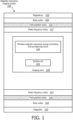
- FIG. 1 is a cross-sectional side view of a magnetic resonance imaging system for wireless magnetic resonance energy harvesting and coil detuning, in accordance with a representative embodiment of the present disclosure.
- the magnetic resonance imaging system 100 in Figure 1 includes a cylindrical magnet 105 with a bore.
- the magnet 105 may be housed in a housing that serves as the exterior surface of the magnetic resonance imaging system 100, but is otherwise the outermost functional element described with respect to the embodiment of Figure 1 .
- Other elements of the magnetic resonance imaging system 100 are provided in the bore of the magnet 105. Additionally, the subject (not shown) being imaged is placed in the bore of the magnet 105.
- the noted cylindrical magnet is only an example, as other types of magnets can be used for magnetic resonance imaging systems, including a split cylindrical magnet or an open magnet.
- the magnetic resonance imaging system 100 in Figure 1 also includes a cylindrical body coil 106 immediately interior to the magnet 105.
- the body coil 106 provides the main uniform, static, magnetic field that excites and aligns the hydrogen atoms. Examples of uniform magnetic fields provided by a body coil 105 are 1.5 Teslas, 3.0 Teslas, or 7.0 Teslas.
- the present disclosure mainly describes using hydrogen atoms, the teachings of the present disclosure can also be used and applied with multiple different types of nuclear/spectroscopy imaging technologies and systems.
- Nuclear/spectroscopy imaging technologies and systems that can use wireless magnetic resonance energy harvesting and coil detuning can use types of atoms including, but not limited to, phosphorous, sodium and carbon.
- the magnetic resonance imaging system 100 in Figure 1 also includes field gradient coils 110.
- the field gradient coil 110 is immediately interior to the body coil 106.
- the field gradient coils are relative low frequency coils used to choose a plane of interest relative to the X, Y and Z axes.
- the field gradient coils 110 are used generate a magnetic field across the subject in the bore of the magnet housing 105 by using a field gradient. This results in different three-dimensional sections or slices within the bore becoming associated with frequencies and a phase encoded coordinate system.
- the magnetic resonance imaging system 100 in Figure 1 also includes a radio frequency coil 107.
- the radio frequency coil 107 is immediately interior to the field gradient coil 110.
- the radio frequency coil 107 is used to deliver the B1 field to selected slices of the imaging zone 108.
- the selected sliced may correspond symmetrically with one or more different three-dimensional sections within the bore.
- the result of the delivery of the B1 field is to manipulate orientations of magnetic spins of hydrogen nuclei within an imaging zone 108 of the magnetic resonance imaging system 100.
- the radio frequency coil 107 is used in the transmit stage, and may be used in some systems for the receive stage. That is, once a transmit cycle is complete, the hydrogen atoms return to original positions, and emanate a weak radio frequency signal. This weak radio frequency signal from the hydrogen atoms returned to their original positions is what is picked up in the receive stage of the magnetic resonance imaging cycle.
- a wireless magnetic resonance energy harvesting and coil detuning circuit 109 is provided in the imaging zone 108.
- the wireless magnetic resonance energy harvesting and coil detuning circuit 109 may provide multiple differing and varying characteristic functions, including:
- the wireless magnetic resonance energy harvesting and coil detuning circuit 109 may be provided with the radio frequency surface coils 102 that are placed close to a patient and body part of interest in order to pick up the weak radio frequency signals in the receive stage.
- the wireless magnetic resonance energy harvesting and coil detuning circuit 109 will function as the detuning circuit for detuning such radio frequency surface coils in a transmit stage while the hydrogen nuclei are being realigned.
- the wireless magnetic resonance energy harvesting and detuning circuit 109 may be provided with a transceiver for sending data of the weak radio frequency signals from the hydrogen atoms of the subject to a processor for analysis and display.
- the wireless magnetic resonance energy harvesting and coil detuning circuit 109 also is provided with an ability to detect and selectively harvest energy from the magnetic resonance imaging system 100 to self-power the wireless magnetic resonance energy harvesting and coil detuning circuit 109 with repurposed energy.
- atoms such as the hydrogen nuclei are first aligned by a main magnetic field from the body coil 106, and then the imaging plane of interest is set from the field gradient coils 110.
- the radio frequency coil 107 provides the B1 field to specified slices within the imaging zone 108.
- the radio frequency surface coil 102 picks up the resulting relatively weak radio frequency resonance signals as the re-aligned nucleis (spins) return to their prior positions.
- the wireless magnetic resonance energy harvesting and coil detuning circuit 109 can tune to a particular frequency of interest to pick up the resonance signals from the B1 field.
- the energy from radio frequency coil 107 is harvested by the wireless magnetic resonance energy harvesting and coil detuning circuit 109.
- the energy from the radio frequency coil 107 is orders of magnitude larger than the resonance signals from the human body
- Radio frequency surface coils 102 work on the principle of Biot-Savart's law.
- the radio frequency surface coils 102 used for receiving these resonance signals can support large currents. So, for multiple reasons, including patient safety and to protect sensitive receiver equipment, the wireless magnetic resonance energy harvesting and coil detuning circuit 109 detunes during the transmit phase when the strong energy from the radio frequency coil 107, the field gradient coil 110, and/or the body coil 105 is emitted.
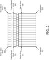
- FIG. 2 is an arrangement of elements for wireless magnetic resonance energy harvesting and coil detuning, in accordance with a representative embodiment of the present disclosure.
- coil segments 201-220 are used to receive the varying radio frequency energy conveyed from the nucleis (spins) re-aligned by the radio frequency coils 107 in Figure 1 .
- the coil segments 201-220 may be, for example, radio frequency surface coils placed on or near a subject being imaged.
- twenty coil segments 201-220 are shown in Figure 2
- a magnetic resonance imaging system 100 may include fewer or more such coil segments 201-220 without departing from the scope of the present teachings.
- some modern magnetic resonance imaging systems have as many as forty-eight (48) different coil segments in one or more of the types of coils described herein.
- Each coil segment 201-220 is connected to a corresponding detune circuit 221-240.
- the detune circuits 221-240 are used to specifically decouple coil segments 201-220 from the energy transmitted by radio frequency coil(s) 107 during a transmit stage of the magnetic resonance imaging system 100. That is, the detune circuits 221-240 are used to ensure that the coil segments 201-220 do not substantially transfer the transmit stage energy from the radio frequency coil(s) 107 to the coil segments 201-220.
- the detune circuits 221-240 are physically connected to the coil segments 201-220.
- the detune circuits 221-240 may even be considered components of coil segments 201-220, such as when a specific detune circuit 221-240 is specifically dedicated to and physically connected to or otherwise physically integrated with a specific coil segment 201-220.
- energy harvest circuits 241-260 are used to harvest wireless energy as explained herein.
- the energy harvest circuits 241-260 can store harvested energy in an energy storage such as a battery (not shown), or may provide the harvested energy directly for use by, for example, the detune circuits 221-240.
- power detect circuits 261-280 are provided.
- the power detect circuits 261-280 detect when power from the radio frequency coil(s) 107 is being transmitted in a Transmit stage. The detection of power from the radio frequency coil(s) 107 is used as the basis to signal, trigger and activate the energy harvest circuits 241-260 to start harvesting energy, and to have the detune circuits 221-240 detune the corresponding coils segments 201-220 of the radio frequency coil.
- the radio frequency coil(s) 107 in Figure 1 may be used for both transmissions in the transmit stage and reception in the receive stage.
- the detune circuits 221-240 can detune the radio frequency coil(s) 107 in the same manner described herein, though in such an embodiment there is less of a danger presented by such radio frequency coil(s) 107.
- the cylindrical radio frequency coil(s) 107 are used for both transmissions in the transmit stage and reception in the receive stage, much of the data from hydrogen nuclei in the subject is lost compared to the data that could be otherwise captured by surface coil segments 201-220.
- using the same radio frequency coil(s) 107 for both the transmit stage and the receive stage is not normally preferred.
- connections between the energy harvest circuit 241-260 and detune circuits 221-240 may be physical connections used to transfer power to the detune circuits 221-240.
- power detect circuits 261-280 may be connected via signal lines to signal the energy harvest circuits 241-260 when to harvest energy (and/or to specifically not harvest energy), and to signal the detune circuits 221-240 when to detune the coil segments 201-220.
- Figure 2 shows a 1 to 1 correspondence for the power detect circuits 261-280, energy harvest circuits 241-260, detune circuits 221-240, and coil segments 201-220.
- multiple detune circuits 221-240 and energy harvest circuits 241-260 can be used with a single detect circuit 261-280 or multiple detect circuits 261-280. That is, a 1 to 1 correspondence is not strictly necessary for the power detect circuits 261-280, energy harvest circuits 241-260, detune circuits 221-240, and coil segments 201-220 in every configuration.
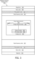
- FIG. 3 is a cross-sectional side view of another magnetic resonance imaging system for wireless magnetic resonance energy harvesting and coil detuning, in accordance with a representative embodiment of the present disclosure.
- a magnetic resonance imaging system 300 includes outer magnet(s) 305, body coil(s) 306, field gradient coil(s) 310, and radio frequency coil(s) 307, each of which is the same as or similar to the corresponding elements in the embodiment of Figure 1 .
- multiple different circuits are provided in the imaging zone 308 in place of the wireless magnetic resonance energy harvesting and coil detuning circuit 109 in the embodiment of Figure 1 .
- the circuits in the imaging zone 308 include radio frequency (RF) surface coil(s) 320, detune circuit(s) 330, energy harvest circuit(s) 350 and power detect sensor(s) 370.
- RF radio frequency
- the radio frequency surface coil(s) 320 are provided to pick up radio frequency signals emanating from the hydrogen atoms in the subject being imaged. For this reason, the radio frequency surface coil 320 is shown as the lowest element in the imaging zone 308, with the understanding that the radio frequency surface coil(s) 320 will be placed on or near the subject being imaged.
- the detune circuit(s) 330 are attached to the radio frequency surface coil(s), and are used to detune the radio frequency surface coil(s) 320 during a transmit stage.
- the detune circuit(s) 330 have the function of decoupling the radio frequency surface coil 320 from the emitted transmitted pulse from the radio frequency coil(s) 307.
- Vartiovaara U.S. Patent No. 8,013,609 (September 6, 2011 ).
- the power detect sensor(s) 370 can be placed anywhere in the imaging zone 308.
- the power detect sensor(s) 370 can also be placed outside of the imaging zone 308, so long as they are in a position to detect pulses emanating from the radio frequency coil(s) 307 in a transmit stage.
- power detect sensors 370 and energy harvest circuit(s) 350 are provided to detect and harvest energy from the radio frequency coil(s) 307, and power and coordinate with the detune circuit(s) 330 to decouple the radio frequency surface coil(s) 320 during the transmit stage.
- the energy harvest circuit(s) 350 in Figure 3 is separated from the detune circuit(s) 330, but with an electrical connection to provide harvested energy to the detune circuit(s) 330.
- the power detect sensor(s) 370 detect pulses from the radio frequency coil(s) 307.
- the pulse is an operational pulse correlated with a (first) preset threshold used to determine whether the pulse indicates that the radio frequency surface coil(s) 320 are in a transmit stage.
- the power detect sensor(s) 370 compares received power to a threshold, and identifies when the operational pulse is being transmitted from the radio frequency coil(s) 307 such that the power is above the threshold.
- the power detect sensor(s) 370 may also identify when power is below a threshold and indicates either that no pulse was generated, or that transmission of a pulse had ended.
- the threshold to confirm a pulse may be the same threshold as the threshold to confirm no pulse, though the thresholds for these two different purposes may also differ.
- the power detect sensor(s) 370 may be connected by a signal transfer line to energy harvest circuit(s) 350 to coordinate harvesting energy, and to detune circuit(s) 330 to coordinate detuning of the radio frequency surface coil(s) 320.
- the energy harvest circuit(s) 350 can include a match circuit for impedance matching in a narrow frequency range in order to transfer some portion of the energy output from, for example, the radio frequency coil(s) 307 to the energy harvest circuit(s) 150.
- Many types of circuits can be used for impedance matching, including transformers and L-networks.
- an inductor can be used to capture energy and a capacitor can be used to store energy in energy harvest circuit(s) 350.
- a specific circuit example of wireless energy harvesting is explained below with respect to Figure 9 .
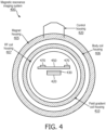
- a magnet housing 405 is designated with a hatch pattern as an outer structure of a magnetic resonance imaging system 400.
- a body coil housing 406 is immediately interior to the magnet housing 405.
- a field gradient coil housing 410 is immediately interior to the body coil housing 406.
- a radio frequency (RF) coil housing 407 is immediately interior to the field gradient coil housing 410.
- a control housing 420 is provided on the magnet housing 405 to house, e.g., external circuitry such as a transceiver.
- two power detect sensors 470 are provided within the radio frequency surface coil to detect when the radio frequency coils within the radio frequency coil housing 407 are transmitting pulses.
- the number of power detect sensors 470 is not limited to two, and may instead be one, the same number as the radio frequency coils within the radio frequency coil housing 407, or another number without departing from the scope of the present teachings.
- An energy harvest circuit 450 is provided to harvest energy from the radio frequency coil(s) in the radio frequency coil housing 407 and/or field gradient coil(s) in the field gradient coil housing 410 and/or the body coil(s) in the body coil housing 406.
- detune circuit(s) 430 are provided with the radio frequency surface coil(s) 420. Energy harvested by the energy harvest circuit(s) 450 is provided to the detune circuit(s) 430. As described herein, the energy can be provided to the detune circuit(s) 430 in real-time or near real-time when the energy is harvested, or can be provided from an energy storage such as a battery. The detune circuit(s) 430 detune the radio frequency coil(s) 420 during the transmit stage based on the detection by the power detect sensors 470 and using the energy harvested by the energy harvest circuit(s) 450.
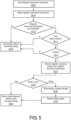
- FIG. 5 is a flow diagram showing an operational method for wireless magnetic resonance energy harvesting and coil detuning, in accordance with a representative embodiment of the present disclosure.
- a magnetic resonance transmission is emitted at block S502.
- the magnetic resonance transmission emitted at block S502 is the radio frequency magnetic resonance transmission from the radio frequency coil(s) 107 as in Figure 1 .
- the emitted magnetic resonance transmission is detected by a wireless power detection sensor, for example, a power detect sensor 370 in Figure 3 .
- a safety check at block S511 may be, for example, a check for a short or open connection in detune circuit(s) 330.
- the safety check at block S511 may also be a check if the detected magnetic resonance transmission power variation is too large, such that the second threshold is higher than the (first) threshold used at block S510.
- Safety checks may also be performed for the magnetic resonance imaging systems 100, 300 generally, such as to confirm that all radio frequency surface devices are able to sustain radio frequency power transmissions, to confirm that radio frequency power is focused in the subject being imaged, and/or that no radio frequency devices are otherwise malfunctioning.
- the determination at block S512 may be an affirmative determination whether or not to detune the radio frequency surface coil(s) 320 based on, for example, whether energy is already stored in a storage device from previous magnetic resonance transmissions.
- FIG. 6 is a circuit diagram for wireless magnetic resonance energy harvesting and coil detuning, in accordance with a representative embodiment of the present disclosure.
- a magnetic resonance imaging system includes a radio frequency surface coil 610 that receives radio frequency signals from, for example, the hydrogen nuclei of water molecules during a receive stage.
- the radio frequency surface coil 610 includes elements of a detune circuit with inductor 696 and capacitor 698.
- a wireless power sensor 650 detects energy from the radio frequency coil(s) 107 or 307 (not shown) when the radio frequency coil(s) 107 or 307 are transmitting pulses, and synchronizes with the wireless energy harvesting circuit 660 to harvest the energy from the radio frequency coil(s) 107 or 307.
- collected energy can be used to directly power the circuits associated with the magnetic resonance imaging system 100, or may be stored in an energy storage 670 such as a battery.
- a signal source (direct) or energy storage 670 is shown in Figure 6 to represent the options to store or directly power circuits using harvested energy.
- a capacitor 698 and inductor 696 are used as the detune circuit for the radio frequency coil 610.
- the wireless power sensor 650 and wireless energy harvesting circuit 660 are placed close to the detune circuit on every channel element of the radio frequency surface coil 610.
- the wireless power sensor 650 and wireless energy harvesting circuit 660 can be connected to the energy storage 670 to toggle between harvesting energy and turning off.
- the energy storage 670 may be, for example, a battery, and may represent a back-up. While the magnetic resonance imaging system is in transmit mode, the energy will be detected, harvested, and repurposed to charge the energy storage 670 or power the detune circuit to be ON. In the receive mode, the detune circuit, the wireless power sensor 650 and the wireless energy harvesting circuit 660 are all turned OFF.
- FIG. 7 is a timing chart for wireless magnetic resonance energy harvesting and coil detuning, in accordance with a representative embodiment of the present disclosure.
- FIG. 7 six timing sequences are shown for transmit, detect, decision(s), harvest, and detune operations. The most important information to be derived from Figure 7 is the relative timing between each operation in any sequence.
- wireless magnetic resonance energy harvesting and coil detuning is not limited the timing or sequence in Figure 7 .
- an operational pulse from a radio frequency coil(s) 107 is emitted in a transmit stage. All four of the other operations shown in Figure 7 occur entirely or substantially entirely during the time the operational pulse is emitted.
- the operational pulse is detected in the detect operation at, or very close to, the very start of the transmit operation. Decisions such as a safety check (block S511) and/or a detune decision (block S512) are made in a decision operation starting immediately after the detect operation. The detect operation and the decision operation occur entirely during the transmit operation.
- the harvest operation starts after the decision operations are completed, such as once the harvest operation is authorized.
- the harvest operation coincides entirely or almost entirely with the detune operation, where energy is harvested and used to detune radio frequency surface coil(s) 320.
- Timing of the detune operation may deviate from timing of the harvest operation when, for example, the harvested energy is to be stored in an energy storage such as a battery, while energy from the battery is used for the detune operation.
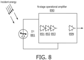
- FIG. 8 is another circuit diagram for wireless magnetic resonance energy harvesting and coil detuning, in accordance with a representative embodiment of the present disclosure.
- the circuit diagram in Figure 8 is for a power detect circuit such as power detect circuits 261-280, power detect sensors 370 or 470, and/or wireless power sensor 650.
- a detector D1 881 can be a Schottky diode with a very low V1, for example, or a similar detector element.
- Output of the detector D1 881 is amplified by an N-stage operational amplifier 890 to produce a detection signal when an operational pulse from radio frequency coil(s) 107 or 307 is detected.
- the N-stage operational amplifier 890 includes a series of operational amplifiers 891, 892, 893 through 89N to amplify the output of the detector D1 881 to produce the detection signal output from the N-stage operational amplifier 890.
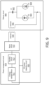
- FIG. 9 is another circuit diagram for wireless magnetic resonance energy harvesting and coil detuning, in accordance with a representative embodiment of the present disclosure.
- the circuit arrangement in Figure 9 includes a detune circuit 980 that includes an inductor 981, a capacitor 982, and two diodes D1 983 and D2 984.
- the two diodes D1 983 and 984 are anti-parallel diodes used as a switch for the capacitor 982.
- Energy collected by inductor L2 is used to detune a radio frequency surface coil that includes the detune circuit 980 but which is otherwise not shown in Figure 9 .
- the detune circuit 980 wirelessly receives harvested energy from a match circuit 932 via an inductor 935 and the inductor 982. While a 2-inductor design is shown in Figure 9 , other types of coupling devices that are based on inductive coupling can also be used.
- a logical signal is received by the detune circuit 980 to switch the anti-parallel diodes D1 983 and D2 984. While diodes D1 983 and D3 984 are shown in Figure 9 , the use of diodes is only representative, and other electrical components and/or circuits can be used in place of parallel diodes D1 983 and D2 984.
- the logical signal is received from the radio frequency power detection circuit 950 via the power management circuit 910, and is received based on the power detection circuit 950 detecting an operational pulse from the radio frequency coil(s) 107 or 307.
- the energy harvest circuit in Figure 9 includes a match circuit 932 for impedance matching in a frequency range in order to transfer some portion of the energy output from the energy storage device 911 via the rectifier circuit 912 and inductors 935, 981.
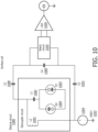
- FIG. 10 is another circuit diagram for wireless magnetic resonance energy harvesting and coil detuning, in accordance with a representative embodiment of the present disclosure.
- the detune circuit 980 is shown in the context of a surface coil, but without the power management circuit 910 and radio frequency power detection circuit 950 from Figure 9 .
- a surface coil includes capacitors C1 1082, C2 1088, C3 1089 and C3 1091.
- the detune circuit 1080 is a decoupler circuit that includes an inductor L2 1081, the capacitor C1 1082, and the two anti-parallel diodes D1 1083 and D2 1084.
- the detune circuit 1080 in Figure 10 is similar to or the same as the detune circuit 980 in Figure 9 , and repetitive descriptions therefore are omitted.
- the anti-parallel diodes D1 1083 and D2 1084 again act as a switch to turn the detune circuit 1080 on and off based on a received instruction signal from, for example, a wireless power detector.
- the surface coil in Figure 10 outputs data to a match circuit 1095 and ultimately to a low noise amplifier (LNA) 1099.
- the low noise amplifier 1099 provides output via a coaxial wire.
- the output from the low noise amplifier 1099 is amplified output of received radio frequency signals received by the surface coil in Figure 10 .
- the received radio frequency signals are from the hydrogen nuclei of the water molecules in the subject being imaged, and are received during the received stage of a cycle.
- the detune circuit 1080 is integrated with the surface coil in Figure 10 , and shares the capacitor C1 1082.
- the detune circuit 1080 is selectively turned ON by an external signal from, for example, a wireless power detector.
- the detune circuit 1080 receives power from a battery or directly from a wireless energy harvest circuit via the inductor L2 1081.
- FIG. 11 shows an exemplary general computer system that includes a set of instructions for wireless magnetic resonance energy harvesting and coil detuning, which may be involved when performing an embodiment of the present disclosure.
- the exemplary general computer system as such is outside the scope of the invention as defined by the claims.
- the exemplary general computer system 1100 is representative of a device that performs logical operations using a processor for the wireless magnetic resonance energy harvesting and coil detuning described herein.
- the general computer system 1100 may be used, for example, to receive the amplified data from the coaxial output in Figure 10 , and may execute a program to generate an image or video representation.
- the general computer system 1100 may be used to control the transmit sequence for magnetic resonance imaging systems 100 or 300, including safety features which may be logically redundant to physical safety features provided by wireless magnetic resonance energy harvesting and coil detuning circuits shown in Figures 1-4 and 6-10 , for example.
- the computer system 1100 can include a set of instructions that can be executed to cause the computer system 1100 to perform any one or more of the methods or computer based functions disclosed herein.
- the computer system 1100 may operate as a standalone device or may be connected, for example, using a network 1101, to other computer systems or peripheral devices.
- the computer system 1100 may be connected, for example, via the coaxial output in Figure 10 , or via a control housing 420 in Figure 4 .
- the computer system 1100 may operate in the capacity of a server or as a client user computer in a server-client user network environment, or as a peer computer system in a peer-to-peer (or distributed) network environment.
- the computer system 1100 can also be implemented as or incorporated into various devices, such as a stationary computer, a mobile computer, a personal computer (PC), a laptop computer, a tablet computer, or any other machine capable of executing a set of instructions (sequential or otherwise) that specify actions to be taken by that machine.
- the computer system 1100 can be incorporated as or in a particular device that in turn is in an integrated system that includes additional devices.
- the computer system 1100 can be implemented using electronic devices that provide audio, video or data communication. Further, while a single computer system 1100 is illustrated, the term "system” shall also be taken to include any collection of systems or subsystems that individually or jointly execute a set, or multiple sets, of instructions to perform one or more computer functions.
- the computer system 1100 includes a processor 1110.
- the processor 1110 for the computer system 1100 may include a dedicated memory, such as random access memory (RAM) and/or read only memory (ROM), which are tangible and non-transitory.
- RAM random access memory
- ROM read only memory
- non-transitory is to be interpreted not as an eternal characteristic of a state, but as a characteristic of a state that will last for a period of time.
- the term “non-transitory” specifically disavows fleeting characteristics such as characteristics of a particular carrier wave or signal or other forms that exist only transitorily in any place at any time.
- a processor is an article of manufacture and/or a machine component.
- a processor for a computer system 1100 is configured to execute software instructions in order to perform functions as described in the various embodiments herein.
- a processor for a computer system 1100 may be a general purpose processor or may be part of an application specific integrated circuit (ASIC).
- a processor for a computer system 1100 may also be a microprocessor, a microcomputer, a processor chip, a controller, a microcontroller, a digital signal processor (DSP), a state machine, or a programmable logic device.
- a processor for a computer system 1100 may also be a logical circuit, including a programmable gate array (PGA) such as a field programmable gate array (FPGA), or another type of circuit that includes discrete gate and/or transistor logic.
- PGA programmable gate array
- FPGA field programmable gate array
- a processor for a computer system 1100 may be a central processing unit (CPU), a graphics processing unit (GPU), or both. Additionally, any processor described herein may include multiple processors, parallel processors, or both. Multiple processors may be included in, or coupled to, a single device or multiple devices.
- CPU central processing unit
- GPU graphics processing unit
- any processor described herein may include multiple processors, parallel processors, or both. Multiple processors may be included in, or coupled to, a single device or multiple devices.
- the computer system 1100 includes a main memory 1120 and a static memory 1130 that can communicate with each other via a bus 1108.
- Memories described herein are tangible storage mediums that can store data and executable instructions, and are non-transitory during the time instructions are stored therein.
- the term "non-transitory” is to be interpreted not as an eternal characteristic of a state, but as a characteristic of a state that will last for a period of time.
- the term “non-transitory” specifically disavows fleeting characteristics such as characteristics of a particular carrier wave or signal or other forms that exist only transitorily in any place at any time.
- a memory described herein is an article of manufacture and/or machine component.
- Memories described herein are computer-readable mediums from which data and executable instructions can be read by a computer.
- Memories as described herein may be random access memory (RAM), read only memory (ROM), flash memory, electrically programmable read only memory (EPROM), electrically erasable programmable read-only memory (EEPROM), registers, a hard disk, or any other form of storage medium known in the art.
- Memories may be volatile or non-volatile, secure and/or encrypted, unsecure and/or unencrypted.
- the computer system 1100 may further include a video display unit 1150, such as a liquid crystal display (LCD), an organic light emitting diode (OLED), a flat panel display, a solid state display, or a cathode ray tube (CRT).
- a video display unit 1150 such as a liquid crystal display (LCD), an organic light emitting diode (OLED), a flat panel display, a solid state display, or a cathode ray tube (CRT).
- the computer system 1100 may include an input device 1160, such as a keyboard/virtual keyboard or touch-sensitive input screen or speech input with speech recognition, and a cursor control device 1170, such as a mouse or touch-sensitive input screen or pad.
- the computer system 1100 can also include a signal generation device 1190, such as a speaker or remote control, and a network interface device 1140.
- dedicated hardware implementations such as application-specific integrated circuits (ASICs), programmable logic arrays and other hardware components, can be constructed to implement one or more of the methods described herein.
- ASICs application-specific integrated circuits
- One or more embodiments described herein may implement functions using two or more specific interconnected hardware modules or devices with related control and data signals that can be communicated between and through the modules. Accordingly, the present disclosure encompasses software, firmware, and hardware implementations. None in the present application should be interpreted as being implemented or implementable solely with software and not hardware such as a tangible non-transitory processor and/or memory.
- the methods described herein may be implemented using a hardware computer system that executes software programs. Further, in an exemplary, non-limited embodiment, implementations can include distributed processing, component/object distributed processing, and parallel processing. Virtual computer system processing can be constructed to implement one or more of the methods or functionality as described herein, and a processor described herein may be used to support a virtual processing environment.
- FIG. 12 is a sequence chart for wireless magnetic resonance energy harvesting and coil detuning, in accordance with a representative embodiment of the present disclosure.
- a transmit/receive cycle is shown.
- the transmit/receive cycle in Figure 12 may be controlled by a computer system 1100 as shown in Figure 11 .
- transmit periods T2, T6, T10, T14 correspond to transmissions of approximately 20 microTeslas maximum from the radio frequency coil(s) 107 or 307 in a transmit stage.
- Receive periods T4, T8, T12, T16 correspond to reception of approximately ⁇ 10 picoTeslas maximum from the hydrogen nuclei of the water molecules in a receive stage.
- post-receive periods T1, T5, T9, T13 are approximately 100 microseconds minimum.
- Post-transmit periods T3, T7, T11, T15 are approximately 10 microseconds minimum.
- the post-transmit periods are significantly shorter than the post-receive periods. This may be due to the need to quickly begin receive operations after a transmission, as the radio frequency signals from stimulated hydrogen nuclei of water molecules in a subject being imaged are relatively weak from the beginning.
- wireless magnetic resonance energy harvesting and coil detuning enables detuning of a coil such as a radio frequency surface coil 320 without using direct current cables connected to a main power supply of a magnetic resonance imaging system 100, 300.
- Wireless magnetic resonance energy harvesting and coil detuning enables reusing energy from coil transmissions in the transmit stages.
- the harvesting of energy is not enough to substantively interfere with the transmissions of energy from the radio frequency coil(s) 107, 307.
- the harvesting of energy may for example, involve capturing less than 5% or even less than 1% of the energy emitted by a radio frequency coil(s) 107, 307 in transmit stages.
- wireless magnetic resonance energy harvesting and coil detuning has been described with reference to particular means, materials and embodiments, wireless magnetic resonance energy harvesting and coil detuning is not intended to be limited to the particulars disclosed; rather wireless magnetic resonance energy harvesting and coil detuning extends to all subject-matter that falls within the scope of the appended claims.
- the present disclosure mainly describes placing power detect circuits within an imaging zone 108, 308 along with other circuits of a wireless magnetic resonance energy harvesting and coil detuning system.
- power detect circuits 261-280 or power sensors 370 can be placed outside of the imaging zone, such as towards the top of the bore and close to the radio frequency coil(s) 107, 307, without departing from the scope of the present teachings.
- safety checks being performed before energy harvesting or detuning is performed.
- safety checks may be performed even while energy is harvested and/or while detuning is performed.
- a safety check may include monitoring harvested energy in real time or near-real time to determine when too much energy is being harvested such that the magnetic resonance imaging system should be shut down.
- the present disclosure mainly described energy storage in terms of batteries.
- other forms of energy storage can be used, even on a short-term basis.
- Harvested energy can be stored, for example, using a superconductor or other form of energy storage without deviating from the teachings of the present application.
- invention merely for convenience and without intending to voluntarily limit the scope of this application to any particular invention, inventive concept or embodiment thereof.
- inventive concept inventive concept or embodiment thereof.
- specific embodiments have been illustrated and described herein, it should be appreciated that any subsequent arrangement designed to achieve the same or similar purpose may be substituted for the specific embodiments shown.
- This disclosure is intended to cover any and all subsequent adaptations or variations of various embodiments. Combinations of the above embodiments, and other embodiments not specifically described herein, will be apparent to those of skill in the art upon reviewing the description. In any case, the scope of the invention is defined by the claims.
- energy is harvested wirelessly during a transmit pulse of a magnetic resonance sequence.
- the energy is used to supply power to other circuits, including, for example, a detune circuit that detunes a radio frequency coil and/or a power detection sensor that detects the transmit pulse.
- An energy harvesting circuit provides operating voltages to the power detection sensor and the detune circuit.
- the energy harvesting circuit and power detection sensor may be individually provided for each channel on field gradient coils of a magnetic resonance imaging system. As a result, power harvesting can be automated, and integrated with power and control management of circuits and sensors in magnetic resonance imaging systems.
Landscapes
- Physics & Mathematics (AREA)
- Condensed Matter Physics & Semiconductors (AREA)
- General Physics & Mathematics (AREA)
- Engineering & Computer Science (AREA)
- Computer Networks & Wireless Communication (AREA)
- Power Engineering (AREA)
- Magnetic Resonance Imaging Apparatus (AREA)
Applications Claiming Priority (2)
| Application Number | Priority Date | Filing Date | Title |
|---|---|---|---|
| US201662401326P | 2016-09-29 | 2016-09-29 | |
| PCT/EP2017/074629 WO2018060332A1 (en) | 2016-09-29 | 2017-09-28 | Wireless magnetic resonance energy harvesting and coil detuning |
Publications (2)
| Publication Number | Publication Date |
|---|---|
| EP3519841A1 EP3519841A1 (en) | 2019-08-07 |
| EP3519841B1 true EP3519841B1 (en) | 2024-12-18 |
Family
ID=60022074
Family Applications (1)
| Application Number | Title | Priority Date | Filing Date |
|---|---|---|---|
| EP17780359.0A Active EP3519841B1 (en) | 2016-09-29 | 2017-09-28 | Wireless magnetic resonance energy harvesting and coil detuning |
Country Status (5)
| Country | Link |
|---|---|
| US (1) | US10816622B2 (enExample) |
| EP (1) | EP3519841B1 (enExample) |
| JP (1) | JP7025417B2 (enExample) |
| CN (1) | CN109844555B (enExample) |
| WO (1) | WO2018060332A1 (enExample) |
Families Citing this family (8)
| Publication number | Priority date | Publication date | Assignee | Title |
|---|---|---|---|---|
| EP3611527B1 (de) * | 2018-08-16 | 2021-07-14 | Siemens Healthcare GmbH | Lokalspule und system zur drahtlosen energieübertragung |
| KR102554226B1 (ko) * | 2018-09-04 | 2023-07-10 | 주식회사 히타치엘지 데이터 스토리지 코리아 | 무선 전력 전송 장치 및 방법 |
| EP3623831A1 (en) | 2018-09-11 | 2020-03-18 | Koninklijke Philips N.V. | Magnetic resonace receive coil with detune circuit and energy harvesting circuit |
| DE102020212901B4 (de) * | 2019-10-14 | 2023-03-23 | Lg Electronics Inc. | Drahtloser leistungssensor |
| WO2022073672A1 (en) * | 2020-10-06 | 2022-04-14 | Koninklijke Philips N.V. | Energy harvesting decoupler for an magnetic resonance imaging (mri) system |
| EP4001944A1 (en) * | 2020-11-12 | 2022-05-25 | Koninklijke Philips N.V. | Radio frequency receiver with detection of a malfunction of a detune circuit |
| US11823723B2 (en) * | 2021-11-22 | 2023-11-21 | International Business Machines Corporation | Memory device with spin-harvesting structure |
| EP4530652A1 (en) * | 2023-09-29 | 2025-04-02 | Koninklijke Philips N.V. | Radio frequency receiver antenna assembly |
Citations (1)
| Publication number | Priority date | Publication date | Assignee | Title |
|---|---|---|---|---|
| US20090237081A1 (en) * | 2008-03-18 | 2009-09-24 | Stephan Biber | Arrangement to detune a reception antenna in a local coil |
Family Cites Families (34)
| Publication number | Priority date | Publication date | Assignee | Title |
|---|---|---|---|---|
| JP3147418B2 (ja) * | 1991-08-09 | 2001-03-19 | 株式会社日立製作所 | Mri用rfコイル |
| US6882128B1 (en) * | 2000-09-27 | 2005-04-19 | Science Applications International Corporation | Method and system for energy reclamation and reuse |
| US6856291B2 (en) * | 2002-08-15 | 2005-02-15 | University Of Pittsburgh- Of The Commonwealth System Of Higher Education | Energy harvesting circuits and associated methods |
| US7400253B2 (en) * | 2005-08-04 | 2008-07-15 | Mhcmos, Llc | Harvesting ambient radio frequency electromagnetic energy for powering wireless electronic devices, sensors and sensor networks and applications thereof |
| US8552597B2 (en) * | 2006-03-31 | 2013-10-08 | Siemens Corporation | Passive RF energy harvesting scheme for wireless sensor |
| EP2016436A1 (en) * | 2006-04-24 | 2009-01-21 | Koninklijke Philips Electronics N.V. | Simple decoupling of a multi-element rf coil, enabling also detuning and matching functionality |
| GB0618087D0 (en) | 2006-09-14 | 2006-10-25 | Imp Innovations Ltd | Magnetic resonance systems |
| CN101573630A (zh) | 2006-12-21 | 2009-11-04 | 皇家飞利浦电子股份有限公司 | 用于mri系统的失谐电路和失谐方法 |
| JP2009261436A (ja) * | 2008-04-22 | 2009-11-12 | Aloka Co Ltd | 超音波診断装置 |
| CN101647699B (zh) * | 2008-08-12 | 2011-08-10 | 株式会社东芝 | 磁共振成像装置及磁共振成像方法 |
| US8294465B2 (en) * | 2010-03-31 | 2012-10-23 | Natalia Gudino | Switched mode pre-amplification and am feedback for on-coil switched mode amplifiers in parallel transmission MRI |
| JP5528266B2 (ja) * | 2010-08-31 | 2014-06-25 | ジーイー・メディカル・システムズ・グローバル・テクノロジー・カンパニー・エルエルシー | コイル装置および磁気共鳴イメージング装置 |
| FR2971054B1 (fr) * | 2011-01-31 | 2014-01-17 | Eads Europ Aeronautic Defence | Dispositif de surveillance de l'integrite et de la sante d'une structure mecanique et procede de fonctionnement d'un tel dispositif |
| DE112012001772T5 (de) * | 2011-04-21 | 2014-03-06 | Philips Deutschland Gmbh | Mehrkanal-HF-Volumenresonator für MRI |
| DE102011080141B4 (de) * | 2011-07-29 | 2015-08-27 | Siemens Aktiengesellschaft | Verfahren zur adaptiven Energieübertragung zu einem Lokalspulensystem |
| CN202288821U (zh) * | 2011-10-17 | 2012-07-04 | 郭海斌 | 针灸枪 |
| KR101343037B1 (ko) | 2011-11-10 | 2013-12-18 | 삼성전자 주식회사 | 자기 공명 영상용 무선 고주파 코일, 그 코일의 전원 제어 방법 및 그 코일을 이용한 자기 공명 영상 장치 |
| CN102535576B (zh) * | 2012-02-17 | 2015-05-20 | 三一重机有限公司 | 一种用于挖掘机液压系统上的能量回收装置 |
| KR101926564B1 (ko) * | 2012-07-11 | 2018-12-11 | 한국전자통신연구원 | 착용형 무선 전력 전송 장치 및 이를 이용한 무선 전력 전송 방법 |
| JP6391911B2 (ja) * | 2013-01-23 | 2018-09-19 | キヤノンメディカルシステムズ株式会社 | 磁気共鳴イメージング装置、及び、rfコイル装置 |
| EP2972445B1 (en) * | 2013-03-13 | 2022-09-07 | Koninklijke Philips N.V. | Multi-element rf transmit coil for magnetic resonance imaging |
| CN103625283B (zh) * | 2013-11-04 | 2016-09-14 | 江苏大学 | 一种车辆驱动系统能量回收装置 |
| JP6456972B2 (ja) * | 2014-03-31 | 2019-01-23 | コーニンクレッカ フィリップス エヌ ヴェKoninklijke Philips N.V. | 磁気共鳴(mr)システムのための低損失デチューン回路を備えた受信コイル及びその作動方法 |
| WO2015200436A1 (en) * | 2014-06-24 | 2015-12-30 | Board Of Trustees Of The University Of Alabama | Wireless power transfer systems and methods |
| JP6553655B2 (ja) * | 2014-07-01 | 2019-07-31 | コーニンクレッカ フィリップス エヌ ヴェKoninklijke Philips N.V. | デチューン回路及びエネルギ捕獲回路を備えたmr受信コイル |
| US9678183B2 (en) * | 2014-08-14 | 2017-06-13 | General Electric Company | Wireless actuator circuit for wireless actuation of micro electromechanical system switch for magnetic resonance imaging |
| US10416213B2 (en) * | 2014-10-29 | 2019-09-17 | Nokomis, Inc. | Ultra-sensitive, ultra-low power RF field sensor |
| US20160131328A1 (en) * | 2014-11-07 | 2016-05-12 | Lighthouse Technologies Limited | Indoor smd led equipped for outdoor usage |
| CN107110924B (zh) * | 2014-12-08 | 2020-09-01 | 皇家飞利浦有限公司 | 用在具有断开警告的磁共振成像系统中的射频接收线圈 |
| CN104648700B (zh) * | 2014-12-16 | 2017-01-11 | 北京空间飞行器总体设计部 | 一种超敏捷无振动空间观测系统及其方法 |
| FR3031849B1 (fr) * | 2015-01-16 | 2017-02-17 | Alstom Transp Tech | Convertisseur d'alimentation reseau et/ou de sous-station de recuperation de l'energie de freinage |
| US9906275B2 (en) * | 2015-09-15 | 2018-02-27 | Energous Corporation | Identifying receivers in a wireless charging transmission field |
| JP2017093223A (ja) * | 2015-11-13 | 2017-05-25 | 株式会社東芝 | 受電装置、送電装置、及び無線電力伝送システム |
| US10326641B2 (en) * | 2016-01-26 | 2019-06-18 | Motorola Mobility Llc | Using RF energy on an uplink channel to transition an unpowered access point to a power-up state |
-
2017
- 2017-09-28 WO PCT/EP2017/074629 patent/WO2018060332A1/en not_active Ceased
- 2017-09-28 CN CN201780060049.8A patent/CN109844555B/zh active Active
- 2017-09-28 EP EP17780359.0A patent/EP3519841B1/en active Active
- 2017-09-28 JP JP2019516686A patent/JP7025417B2/ja active Active
- 2017-09-28 US US16/334,961 patent/US10816622B2/en active Active
Patent Citations (1)
| Publication number | Priority date | Publication date | Assignee | Title |
|---|---|---|---|---|
| US20090237081A1 (en) * | 2008-03-18 | 2009-09-24 | Stephan Biber | Arrangement to detune a reception antenna in a local coil |
Also Published As
| Publication number | Publication date |
|---|---|
| CN109844555B (zh) | 2025-01-17 |
| US20190265317A1 (en) | 2019-08-29 |
| JP2019534741A (ja) | 2019-12-05 |
| JP7025417B2 (ja) | 2022-02-24 |
| US10816622B2 (en) | 2020-10-27 |
| WO2018060332A1 (en) | 2018-04-05 |
| EP3519841A1 (en) | 2019-08-07 |
| CN109844555A (zh) | 2019-06-04 |
Similar Documents
| Publication | Publication Date | Title |
|---|---|---|
| EP3519841B1 (en) | Wireless magnetic resonance energy harvesting and coil detuning | |
| JP6456972B2 (ja) | 磁気共鳴(mr)システムのための低損失デチューン回路を備えた受信コイル及びその作動方法 | |
| EP3164728B1 (en) | Mr receive coil with detune circuit and energy harvesting circuit | |
| US10374465B2 (en) | Wireless power transmitter and control method therefor | |
| US20190312465A1 (en) | Wireless power transmitter and control method therefor | |
| KR101645199B1 (ko) | Mri에 대한 연결되지 않은 트랜시버 코일들의 자동 디튜닝 | |
| US9057768B2 (en) | Local coil for a magnetic resonance device | |
| JP2000514670A (ja) | Nmr及びmri装置用アンテナシステム | |
| US9678183B2 (en) | Wireless actuator circuit for wireless actuation of micro electromechanical system switch for magnetic resonance imaging | |
| CN104280702B (zh) | 用于成像的mrt系统的局部线圈 | |
| US11333724B2 (en) | Apparatus and method for real-time monitoring and control of local coils | |
| CN110837069B (zh) | 局部线圈和用于无线能量传输的系统 | |
| US10917138B2 (en) | Near-field communications device | |
| US9903926B2 (en) | Determination of communication latency in magnetic resonance tomography systems | |
| CN110888095B (zh) | 具有失谐电路和能量收集电路的磁共振接收线圈 | |
| CN1890577A (zh) | 用于去调谐mr设备的谐振电路的电路装置 | |
| JP6857646B2 (ja) | 磁気共鳴検査システム用の局所フィールド監視ユニットを有するrf送信モジュール | |
| US11841406B2 (en) | Magnetic resonance tomograph and method for rapid switchover from TX to RX | |
| US20170307700A1 (en) | Wireless detection coil system | |
| CN213934173U (zh) | 用于磁共振断层造影仪的天线装置以及磁共振断层造影仪 | |
| US12429542B2 (en) | Apparatus and method for interference suppression in a magnetic resonance tomography unit | |
| CN120883074A (zh) | 具有指示电路的射频电缆陷波器组件 |
Legal Events
| Date | Code | Title | Description |
|---|---|---|---|
| STAA | Information on the status of an ep patent application or granted ep patent |
Free format text: STATUS: UNKNOWN |
|
| STAA | Information on the status of an ep patent application or granted ep patent |
Free format text: STATUS: THE INTERNATIONAL PUBLICATION HAS BEEN MADE |
|
| PUAI | Public reference made under article 153(3) epc to a published international application that has entered the european phase |
Free format text: ORIGINAL CODE: 0009012 |
|
| STAA | Information on the status of an ep patent application or granted ep patent |
Free format text: STATUS: REQUEST FOR EXAMINATION WAS MADE |
|
| 17P | Request for examination filed |
Effective date: 20190429 |
|
| AK | Designated contracting states |
Kind code of ref document: A1 Designated state(s): AL AT BE BG CH CY CZ DE DK EE ES FI FR GB GR HR HU IE IS IT LI LT LU LV MC MK MT NL NO PL PT RO RS SE SI SK SM TR |
|
| AX | Request for extension of the european patent |
Extension state: BA ME |
|
| DAV | Request for validation of the european patent (deleted) | ||
| DAX | Request for extension of the european patent (deleted) | ||
| RAP1 | Party data changed (applicant data changed or rights of an application transferred) |
Owner name: KONINKLIJKE PHILIPS N.V. |
|
| STAA | Information on the status of an ep patent application or granted ep patent |
Free format text: STATUS: EXAMINATION IS IN PROGRESS |
|
| 17Q | First examination report despatched |
Effective date: 20220222 |
|
| GRAP | Despatch of communication of intention to grant a patent |
Free format text: ORIGINAL CODE: EPIDOSNIGR1 |
|
| STAA | Information on the status of an ep patent application or granted ep patent |
Free format text: STATUS: GRANT OF PATENT IS INTENDED |
|
| INTG | Intention to grant announced |
Effective date: 20240719 |
|
| GRAS | Grant fee paid |
Free format text: ORIGINAL CODE: EPIDOSNIGR3 |
|
| GRAA | (expected) grant |
Free format text: ORIGINAL CODE: 0009210 |
|
| STAA | Information on the status of an ep patent application or granted ep patent |
Free format text: STATUS: THE PATENT HAS BEEN GRANTED |
|
| AK | Designated contracting states |
Kind code of ref document: B1 Designated state(s): AL AT BE BG CH CY CZ DE DK EE ES FI FR GB GR HR HU IE IS IT LI LT LU LV MC MK MT NL NO PL PT RO RS SE SI SK SM TR |
|
| REG | Reference to a national code |
Ref country code: GB Ref legal event code: FG4D |
|
| REG | Reference to a national code |
Ref country code: CH Ref legal event code: EP |
|
| REG | Reference to a national code |
Ref country code: DE Ref legal event code: R096 Ref document number: 602017086835 Country of ref document: DE |
|
| REG | Reference to a national code |
Ref country code: IE Ref legal event code: FG4D |
|
| REG | Reference to a national code |
Ref country code: DE Ref legal event code: R084 Ref document number: 602017086835 Country of ref document: DE |
|
| REG | Reference to a national code |
Ref country code: GB Ref legal event code: 746 Effective date: 20250217 |
|
| REG | Reference to a national code |
Ref country code: LT Ref legal event code: MG9D |
|
| PG25 | Lapsed in a contracting state [announced via postgrant information from national office to epo] |
Ref country code: HR Free format text: LAPSE BECAUSE OF FAILURE TO SUBMIT A TRANSLATION OF THE DESCRIPTION OR TO PAY THE FEE WITHIN THE PRESCRIBED TIME-LIMIT Effective date: 20241218 |
|
| PG25 | Lapsed in a contracting state [announced via postgrant information from national office to epo] |
Ref country code: FI Free format text: LAPSE BECAUSE OF FAILURE TO SUBMIT A TRANSLATION OF THE DESCRIPTION OR TO PAY THE FEE WITHIN THE PRESCRIBED TIME-LIMIT Effective date: 20241218 |
|
| PG25 | Lapsed in a contracting state [announced via postgrant information from national office to epo] |
Ref country code: BG Free format text: LAPSE BECAUSE OF FAILURE TO SUBMIT A TRANSLATION OF THE DESCRIPTION OR TO PAY THE FEE WITHIN THE PRESCRIBED TIME-LIMIT Effective date: 20241218 |
|
| PG25 | Lapsed in a contracting state [announced via postgrant information from national office to epo] |
Ref country code: NO Free format text: LAPSE BECAUSE OF FAILURE TO SUBMIT A TRANSLATION OF THE DESCRIPTION OR TO PAY THE FEE WITHIN THE PRESCRIBED TIME-LIMIT Effective date: 20250318 |
|
| REG | Reference to a national code |
Ref country code: NL Ref legal event code: MP Effective date: 20241218 |
|
| PG25 | Lapsed in a contracting state [announced via postgrant information from national office to epo] |
Ref country code: LV Free format text: LAPSE BECAUSE OF FAILURE TO SUBMIT A TRANSLATION OF THE DESCRIPTION OR TO PAY THE FEE WITHIN THE PRESCRIBED TIME-LIMIT Effective date: 20241218 Ref country code: GR Free format text: LAPSE BECAUSE OF FAILURE TO SUBMIT A TRANSLATION OF THE DESCRIPTION OR TO PAY THE FEE WITHIN THE PRESCRIBED TIME-LIMIT Effective date: 20250319 |
|
| PG25 | Lapsed in a contracting state [announced via postgrant information from national office to epo] |
Ref country code: RS Free format text: LAPSE BECAUSE OF FAILURE TO SUBMIT A TRANSLATION OF THE DESCRIPTION OR TO PAY THE FEE WITHIN THE PRESCRIBED TIME-LIMIT Effective date: 20250318 |
|
| PG25 | Lapsed in a contracting state [announced via postgrant information from national office to epo] |
Ref country code: NL Free format text: LAPSE BECAUSE OF FAILURE TO SUBMIT A TRANSLATION OF THE DESCRIPTION OR TO PAY THE FEE WITHIN THE PRESCRIBED TIME-LIMIT Effective date: 20241218 |
|
| REG | Reference to a national code |
Ref country code: AT Ref legal event code: MK05 Ref document number: 1752649 Country of ref document: AT Kind code of ref document: T Effective date: 20241218 |
|
| PG25 | Lapsed in a contracting state [announced via postgrant information from national office to epo] |
Ref country code: SM Free format text: LAPSE BECAUSE OF FAILURE TO SUBMIT A TRANSLATION OF THE DESCRIPTION OR TO PAY THE FEE WITHIN THE PRESCRIBED TIME-LIMIT Effective date: 20241218 |
|
| PG25 | Lapsed in a contracting state [announced via postgrant information from national office to epo] |
Ref country code: PL Free format text: LAPSE BECAUSE OF FAILURE TO SUBMIT A TRANSLATION OF THE DESCRIPTION OR TO PAY THE FEE WITHIN THE PRESCRIBED TIME-LIMIT Effective date: 20241218 |
|
| PG25 | Lapsed in a contracting state [announced via postgrant information from national office to epo] |
Ref country code: ES Free format text: LAPSE BECAUSE OF FAILURE TO SUBMIT A TRANSLATION OF THE DESCRIPTION OR TO PAY THE FEE WITHIN THE PRESCRIBED TIME-LIMIT Effective date: 20241218 |
|
| PG25 | Lapsed in a contracting state [announced via postgrant information from national office to epo] |
Ref country code: IS Free format text: LAPSE BECAUSE OF FAILURE TO SUBMIT A TRANSLATION OF THE DESCRIPTION OR TO PAY THE FEE WITHIN THE PRESCRIBED TIME-LIMIT Effective date: 20250418 |
|
| PG25 | Lapsed in a contracting state [announced via postgrant information from national office to epo] |
Ref country code: PT Free format text: LAPSE BECAUSE OF FAILURE TO SUBMIT A TRANSLATION OF THE DESCRIPTION OR TO PAY THE FEE WITHIN THE PRESCRIBED TIME-LIMIT Effective date: 20250421 |
|
| PG25 | Lapsed in a contracting state [announced via postgrant information from national office to epo] |
Ref country code: EE Free format text: LAPSE BECAUSE OF FAILURE TO SUBMIT A TRANSLATION OF THE DESCRIPTION OR TO PAY THE FEE WITHIN THE PRESCRIBED TIME-LIMIT Effective date: 20241218 |
|
| PG25 | Lapsed in a contracting state [announced via postgrant information from national office to epo] |
Ref country code: AT Free format text: LAPSE BECAUSE OF FAILURE TO SUBMIT A TRANSLATION OF THE DESCRIPTION OR TO PAY THE FEE WITHIN THE PRESCRIBED TIME-LIMIT Effective date: 20241218 Ref country code: RO Free format text: LAPSE BECAUSE OF FAILURE TO SUBMIT A TRANSLATION OF THE DESCRIPTION OR TO PAY THE FEE WITHIN THE PRESCRIBED TIME-LIMIT Effective date: 20241218 |
|
| PG25 | Lapsed in a contracting state [announced via postgrant information from national office to epo] |
Ref country code: SK Free format text: LAPSE BECAUSE OF FAILURE TO SUBMIT A TRANSLATION OF THE DESCRIPTION OR TO PAY THE FEE WITHIN THE PRESCRIBED TIME-LIMIT Effective date: 20241218 |
|
| PG25 | Lapsed in a contracting state [announced via postgrant information from national office to epo] |
Ref country code: CZ Free format text: LAPSE BECAUSE OF FAILURE TO SUBMIT A TRANSLATION OF THE DESCRIPTION OR TO PAY THE FEE WITHIN THE PRESCRIBED TIME-LIMIT Effective date: 20241218 |
|
| PG25 | Lapsed in a contracting state [announced via postgrant information from national office to epo] |
Ref country code: IT Free format text: LAPSE BECAUSE OF FAILURE TO SUBMIT A TRANSLATION OF THE DESCRIPTION OR TO PAY THE FEE WITHIN THE PRESCRIBED TIME-LIMIT Effective date: 20241218 |
|
| PG25 | Lapsed in a contracting state [announced via postgrant information from national office to epo] |
Ref country code: SE Free format text: LAPSE BECAUSE OF FAILURE TO SUBMIT A TRANSLATION OF THE DESCRIPTION OR TO PAY THE FEE WITHIN THE PRESCRIBED TIME-LIMIT Effective date: 20241218 |
|
| REG | Reference to a national code |
Ref country code: DE Ref legal event code: R097 Ref document number: 602017086835 Country of ref document: DE |
|
| PG25 | Lapsed in a contracting state [announced via postgrant information from national office to epo] |
Ref country code: DK Free format text: LAPSE BECAUSE OF FAILURE TO SUBMIT A TRANSLATION OF THE DESCRIPTION OR TO PAY THE FEE WITHIN THE PRESCRIBED TIME-LIMIT Effective date: 20241218 |
|
| PGFP | Annual fee paid to national office [announced via postgrant information from national office to epo] |
Ref country code: DE Payment date: 20250926 Year of fee payment: 9 |
|
| PGFP | Annual fee paid to national office [announced via postgrant information from national office to epo] |
Ref country code: GB Payment date: 20250923 Year of fee payment: 9 |
|
| PLBE | No opposition filed within time limit |
Free format text: ORIGINAL CODE: 0009261 |
|
| STAA | Information on the status of an ep patent application or granted ep patent |
Free format text: STATUS: NO OPPOSITION FILED WITHIN TIME LIMIT |
|
| 26N | No opposition filed |
Effective date: 20250919 |