EP3519142B1 - Verfahren zur oberflächenbehandlung eines artikels - Google Patents
Verfahren zur oberflächenbehandlung eines artikels Download PDFInfo
- Publication number
- EP3519142B1 EP3519142B1 EP17791459.5A EP17791459A EP3519142B1 EP 3519142 B1 EP3519142 B1 EP 3519142B1 EP 17791459 A EP17791459 A EP 17791459A EP 3519142 B1 EP3519142 B1 EP 3519142B1
- Authority
- EP
- European Patent Office
- Prior art keywords
- spraying head
- robotic arm
- designed
- torque
- handling device
- Prior art date
- Legal status (The legal status is an assumption and is not a legal conclusion. Google has not performed a legal analysis and makes no representation as to the accuracy of the status listed.)
- Active
Links
Images


Classifications
-
- B—PERFORMING OPERATIONS; TRANSPORTING
- B25—HAND TOOLS; PORTABLE POWER-DRIVEN TOOLS; MANIPULATORS
- B25J—MANIPULATORS; CHAMBERS PROVIDED WITH MANIPULATION DEVICES
- B25J9/00—Program-controlled manipulators
- B25J9/16—Program controls
- B25J9/1679—Program controls characterised by the tasks executed
-
- B—PERFORMING OPERATIONS; TRANSPORTING
- B25—HAND TOOLS; PORTABLE POWER-DRIVEN TOOLS; MANIPULATORS
- B25J—MANIPULATORS; CHAMBERS PROVIDED WITH MANIPULATION DEVICES
- B25J11/00—Manipulators not otherwise provided for
- B25J11/0075—Manipulators for painting or coating
-
- B—PERFORMING OPERATIONS; TRANSPORTING
- B25—HAND TOOLS; PORTABLE POWER-DRIVEN TOOLS; MANIPULATORS
- B25J—MANIPULATORS; CHAMBERS PROVIDED WITH MANIPULATION DEVICES
- B25J13/00—Controls for manipulators
- B25J13/08—Controls for manipulators by means of sensing devices, e.g. viewing or touching devices
- B25J13/085—Force or torque sensors
-
- B—PERFORMING OPERATIONS; TRANSPORTING
- B25—HAND TOOLS; PORTABLE POWER-DRIVEN TOOLS; MANIPULATORS
- B25J—MANIPULATORS; CHAMBERS PROVIDED WITH MANIPULATION DEVICES
- B25J9/00—Program-controlled manipulators
- B25J9/16—Program controls
- B25J9/1628—Program controls characterised by the control loop
- B25J9/1633—Program controls characterised by the control loop compliant, force, torque control, e.g. combined with position control
-
- B—PERFORMING OPERATIONS; TRANSPORTING
- B28—WORKING CEMENT, CLAY, OR STONE
- B28B—SHAPING CLAY OR OTHER CERAMIC COMPOSITIONS; SHAPING SLAG; SHAPING MIXTURES CONTAINING CEMENTITIOUS MATERIAL, e.g. PLASTER
- B28B11/00—Apparatus or processes for treating or working the shaped or preshaped articles
- B28B11/04—Apparatus or processes for treating or working the shaped or preshaped articles for coating or applying engobing layers
- B28B11/048—Apparatus or processes for treating or working the shaped or preshaped articles for coating or applying engobing layers by spraying or projecting
-
- B—PERFORMING OPERATIONS; TRANSPORTING
- B28—WORKING CEMENT, CLAY, OR STONE
- B28B—SHAPING CLAY OR OTHER CERAMIC COMPOSITIONS; SHAPING SLAG; SHAPING MIXTURES CONTAINING CEMENTITIOUS MATERIAL, e.g. PLASTER
- B28B17/00—Details of, or accessories for, apparatus for shaping the material; Auxiliary measures taken in connection with such shaping
- B28B17/0063—Control arrangements
- B28B17/0081—Process control
-
- G—PHYSICS
- G05—CONTROLLING; REGULATING
- G05B—CONTROL OR REGULATING SYSTEMS IN GENERAL; FUNCTIONAL ELEMENTS OF SUCH SYSTEMS; MONITORING OR TESTING ARRANGEMENTS FOR SUCH SYSTEMS OR ELEMENTS
- G05B19/00—Program-control systems
- G05B19/02—Program-control systems electric
- G05B19/42—Recording and playback systems, i.e. in which the program is recorded from a cycle of operations, e.g. the cycle of operations being manually controlled, after which this record is played back on the same machine
- G05B19/423—Teaching successive positions by walk-through, i.e. the tool head or end effector being grasped and guided directly, with or without servo-assistance, to follow a path
-
- G—PHYSICS
- G05—CONTROLLING; REGULATING
- G05B—CONTROL OR REGULATING SYSTEMS IN GENERAL; FUNCTIONAL ELEMENTS OF SUCH SYSTEMS; MONITORING OR TESTING ARRANGEMENTS FOR SUCH SYSTEMS OR ELEMENTS
- G05B2219/00—Program-control systems
- G05B2219/30—Nc systems
- G05B2219/36—Nc in input of data, input key till input tape
- G05B2219/36184—Record actions of human expert, teach by showing
-
- G—PHYSICS
- G05—CONTROLLING; REGULATING
- G05B—CONTROL OR REGULATING SYSTEMS IN GENERAL; FUNCTIONAL ELEMENTS OF SUCH SYSTEMS; MONITORING OR TESTING ARRANGEMENTS FOR SUCH SYSTEMS OR ELEMENTS
- G05B2219/00—Program-control systems
- G05B2219/30—Nc systems
- G05B2219/36—Nc in input of data, input key till input tape
- G05B2219/36401—Record play back, teach position and record it then play back
-
- G—PHYSICS
- G05—CONTROLLING; REGULATING
- G05B—CONTROL OR REGULATING SYSTEMS IN GENERAL; FUNCTIONAL ELEMENTS OF SUCH SYSTEMS; MONITORING OR TESTING ARRANGEMENTS FOR SUCH SYSTEMS OR ELEMENTS
- G05B2219/00—Program-control systems
- G05B2219/30—Nc systems
- G05B2219/36—Nc in input of data, input key till input tape
- G05B2219/36442—Automatically teaching, teach by showing
-
- G—PHYSICS
- G05—CONTROLLING; REGULATING
- G05B—CONTROL OR REGULATING SYSTEMS IN GENERAL; FUNCTIONAL ELEMENTS OF SUCH SYSTEMS; MONITORING OR TESTING ARRANGEMENTS FOR SUCH SYSTEMS OR ELEMENTS
- G05B2219/00—Program-control systems
- G05B2219/30—Nc systems
- G05B2219/39—Robotics, robotics to robotics hand
- G05B2219/39101—Cooperation with one or more rotating workpiece holders, manipulators
-
- G—PHYSICS
- G05—CONTROLLING; REGULATING
- G05B—CONTROL OR REGULATING SYSTEMS IN GENERAL; FUNCTIONAL ELEMENTS OF SUCH SYSTEMS; MONITORING OR TESTING ARRANGEMENTS FOR SUCH SYSTEMS OR ELEMENTS
- G05B2219/00—Program-control systems
- G05B2219/30—Nc systems
- G05B2219/39—Robotics, robotics to robotics hand
- G05B2219/39325—External force control, additional loop comparing forces corrects position
-
- G—PHYSICS
- G05—CONTROLLING; REGULATING
- G05B—CONTROL OR REGULATING SYSTEMS IN GENERAL; FUNCTIONAL ELEMENTS OF SUCH SYSTEMS; MONITORING OR TESTING ARRANGEMENTS FOR SUCH SYSTEMS OR ELEMENTS
- G05B2219/00—Program-control systems
- G05B2219/30—Nc systems
- G05B2219/45—Nc applications
- G05B2219/45013—Spraying, coating, painting
-
- G—PHYSICS
- G05—CONTROLLING; REGULATING
- G05B—CONTROL OR REGULATING SYSTEMS IN GENERAL; FUNCTIONAL ELEMENTS OF SUCH SYSTEMS; MONITORING OR TESTING ARRANGEMENTS FOR SUCH SYSTEMS OR ELEMENTS
- G05B2219/00—Program-control systems
- G05B2219/30—Nc systems
- G05B2219/45—Nc applications
- G05B2219/45065—Sealing, painting robot
Definitions
- the present invention concerns a method and a plant for the surface treatment of an article.
- the present invention is advantageously applied in the field of enamelling of ceramic articles, to which the following description explicitly refers without loss of generality.
- robotic devices In the field of the working of ceramic articles, robotic devices are known to be used supporting spraying heads for painting and/or enamelling the surfaces.
- PTP point to point programming
- off-line programming programming by self-learning
- the various actions of the robot are planned on a remote computer using a programming language and then sent to the robot.
- the object of the present invention is to provide a method and a plant for the surface treatment of an article, which overcome, at least partially, the drawbacks of the known art and are, at the same time, easy and inexpensive to produce.
- Document US2009259412A1 discloses a system for controlling position and orientation of an object.
- a sensor is adapted to measure forces and torques caused by changes in position and orientation of a first part relative to a second part.
- a method and a plant are provided for surface treatment according to the following independent claims and, preferably, in any one of the claims depending directly or indirectly on the independent claims.
- “torque” we mean “moment of a force” or in any case another quantity containing (more precisely, a function of) the moment of a force.
- “Moment of a force” (or “mechanical moment”) has the common meaning of the aptitude of a force to impart a rotation to a rigid body around a point (in a plane) or an axis (in space) when said force is not applied to the centre of mass.
- force we also mean (in addition to the meaning normally given to this term) another quantity containing (more precisely, a function of) the force. According to some embodiments, “force” means force according to its normal meaning.
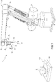
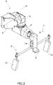
- the number 1 indicates overall a plant for the treatment of an article 2.
- the plant 1 comprises a robotic device 3 which, in turn, comprises a spraying head 4, which is designed to emit a jet of a substance for covering at least a part of the surface of the article 2; a robotic arm 5, which is movable with at least six degrees of freedom and on which the spraying head 4 is fitted; a control system 6 ( figure 4 ); and a driving control assembly 7.
- the control system 6 comprises a storage unit 8 and is designed to control the movement of the robotic arm 5 to move the spraying head 4. In particular, the control system 6 is also designed to adjust the operation of the spraying head 4.
- the driving control assembly 7 is designed to be operated by an operator (not illustrated) to transfer movement indications for the robotic arm 5.
- the contact unit is also designed to transfer the operation indications for the spraying head 4.
- the robotic arm 5 ( figures 1 and 2 ) comprises several sections connected to one another in succession. Each section can be rotated with respect to the preceding one around a respective rotation axis A.
- the rotation around each of the axes A represents a degree of freedom of the robotic arm 5.
- the robotic arm 5 has six degrees of freedom and, more precisely, six axes A of rotation.
- the robotic arm 5 is typically an industrial type anthropomorphic robot, for example it can be the robot GA-OL by Gaiotto Automation SpA.
- the robotic arm 5 can also have more than six degrees of freedom (in particular, more than six rotation axes A). In some cases, the degrees of freedom can be five axes of rotation and a translation (for example horizontal or vertical).
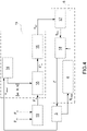
- the driving control assembly 7 comprises a handling device 9 on which, in use, the operator exerts a force and a torque F c ( figure 4 ); a sensor 10, which is connected to the handling device 9 and is designed to detect the force and the torque F s applied to the handling device 9; and a processing system 11, which is designed to provide movement indications for the robotic arm 5 as a function of the items detected by the sensor 10 (more precisely as a function of the force and torque F s detected).
- the senor 10 has (at least) six degrees of freedom and is able to measure (at least) three forces and three torques (in a Cartesian reference system).
- the sensor 10 can be any known device able to perform the functions described above.
- the senor 10 is, for example, the FTSens which, having measured three forces and three torques, is able to transmit them in digital format on a CAN network.
- FTSens has been developed by IIT (Italian Institute of Technology) of Genoa.
- IIT International Institute of Technology
- the measurements are taken using strain gauge technology, based on the deformation of strain gauges (of electrical/resistance type) located inside the body of the sensor.
- the FTSens sensor is provided with a DSP 16-bit microcontroller (dsPIC30F4013), able to sample up to six analog channels, and an analog-digital converter connected to the six channels.
- the DSPic deals with the synchronization and sampling, transmission of the digital data to the CAN, filtering and transformation of the signal read by the strain gauges into forces and torques, via multiplication by the transformation matrix characteristic of the sensor.
- the senor 10 is the Mini 45 by ATI, provided with force / torque sensors with 6 axes which allow measurement of all six force and torque components (Fx, Fy, Fz, Mx, My, Mz) via the use of a transducer.
- the ATI sensors are provided with silicon strain gauges, which provide excellent immunity to disturbances.
- the communication interface with the sensor can be made by using one of the following protocols: FTN (Ethernet, also with ProfiNet option), FTD (PCI, USB), FTS (analog voltage 0 - 10 V, DIO) or FTW (Wireless).
- the storage unit 8 is designed to store the q robot movements made by the robotic arm 5 while the spraying head 4 is moved by the operator by means of the driving control assembly 7.
- the control system 6 is designed to control the movement of the robotic arm 5 as a function of the q robot movements stored by the storage unit 8.
- the control system 6 is designed to control the movement of the robotic arm 5 so that the robotic arm 5 (and the spraying head 4) substantially repeats the q robot movements stored by the storage unit 8, more specifically so that the spraying head 4 substantially repeats the movements carried out while the operator moves the spraying head 4.
- the movement of the robotic arm 5 is the movement in space of each movable part of the robotic arm 5 in space.
- the handling device 9 is fitted on the robotic arm 5 (more specifically, on the sensor 10).
- the handling device 9 is fitted on the robotic arm 5 in the area of the spraying head 4, in particular in the area of an end of the robotic arm 5. More precisely, the handling device 9 is connected to the robotic arm 5 via the sensor 10 (which supports the handling device 9). According to some embodiments, the sensor 10 is fitted on the robotic arm 5.
- the senor 10 is arranged on the robotic arm 5 between the handling device 9 and the position in which the spraying head 4 is fitted on the robotic arm 5. In this way, the sensor 10 does not detect static or dynamic effects relative to the spraying head 4 (and, therefore, processing of the data detected by the sensor 10 is simpler and more accurate).
- the handling device 9 (more precisely the sensor 10) is fitted on the robotic arm 5 between the spraying head and the cited (at least six) degrees of freedom.
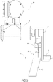
- the handling device 9 comprises at least a handgrip 12, which is designed to be grasped by the operator to move the robotic arm 5 (and, therefore, the spraying head 4) .
- the handling device 9 comprises (at least) two handgrips 12, which are designed to be grasped by the operator to move the robotic arm 5 (and, therefore, the spraying head 4) and are connected to one another in an integral manner, in particular by means of a connection element (of the handling device 9).
- the connection element comprises (more precisely is) a bar transverse to the handgrips 12.
- the transverse bar is fitted on the sensor 10; more precisely, the transverse bar is between the sensor 10 and the handgrip/s 12.
- the spraying head 4 is fitted on the robotic arm 5 by means of a support 4', which projects from the robotic arm 5 (in particular, from one end of the robotic arm 5).
- the support 4' has a first end connected to the robotic arm 5, extends (downwards) beyond the sensor 10 and has a coupling area (at a second end opposite the first end) to which the spraying head 4 is connected.
- the sensor 10 is arranged between the handling device 9 and the first end.
- the support 4' extends between the two handgrips 12. In these cases, the spraying head 4 is arranged between the two handgrips 12.
- the support 4' extends from the robotic arm 5 substantially in a horizontal direction.
- the driving control assembly 7 (in particular, the handling device 9) comprises controls (for example, push-buttons, levers etc.) which are designed to be operated by the operator to adjust over time at least one operating parameter of the spraying head 10.
- the storage unit 8 is designed to store the adjustment of the operating parameter (and the variation thereof in time);
- the control system 6 is designed to adjust operation of the spraying head 4 so that the adjustment of the operating parameter (and the variation thereof in time) stored is substantially repeated, in particular in a manner coordinated with the movements made by the robotic arm 5.
- the driving control assembly 7 is designed to provide indications on the operating parameter (and the variation thereof over time) to the control system 6, which is designed to operate the spraying head 4 as a function of the indications received from the driving control assembly 7.
- the operating parameter is chosen from the group consisting of: adjustment of the flow (quantity per time unit) of the covering substance coming out of the spraying head 4, adjustment of the degree of pulverization of the covering substance coming out of the spraying head 4, adjustment of the width of the jet of covering substance coming out of the spraying head 4, adjustment of the shape of the jet of covering substance coming out of the spraying head 4 (and a combination thereof).
- said operating parameter is chosen from the group consisting of: adjustment of the flow (quantity per time unit) of the covering substance coming out of the spraying head 4, adjustment of the degree of pulverization of the covering substance coming out of the spraying head 4, adjustment of the width (or shape) of the jet of the covering substance coming out of the spraying head 4 (and a combination thereof).
- said operating parameter is the adjustment of the flow of covering substance coming out of the spraying head 4.
- the operating parameter can also simply be activation (on) and de-activation (off) of the jet.
- the driving control assembly 7 (in particular, the handling device 9) comprises a control for enabling movement of the robotic arm 5 (normally called “dead man” in technical jargon) and allows stoppage of the robotic arm 5 in the event of an emergency.
- this command comprises a push-button which must be kept pressed by the operator until the robotic arm 5 is enabled to move. If, in use, this push-button is released or pressed for too long, the control system 6 disables the possibility of movement of the robotic arm 5.
- the plant 1 also comprises a device 13 for movement of the article 2;
- the driving control assembly 7 (in particular, the handling device 9) comprises a command (e.g. a push-button or a lever) designed to be operated by the operator to control the device 13 for movement of the article 2.
- the storage unit 8 is designed to store the position (orientation) of the article 2 set by the operator (and the variation thereof in time).
- the control system 6 is designed to adjust the operation of the device 13 for movement of the article 2 on the basis of the position (orientation) of the article 2 (and the variation thereof in time) stored in the storage unit 8. More specifically, the control system 6 is designed to adjust the operation of the device 13 for movement of the article 2 so as to repeat the position (orientation) of the article 2 (and the variation thereof in time) stored in the storage unit 8.
- the device 13 comprises a rotating platform 13' on which, in use, the article 2 is arranged.
- the platform 13' rotates around a vertical axis (not illustrated).
- the processing system 11 is designed to estimate a non-contact force and torque F nc as a function of static and dynamic components resulting from the load (in particular, the handling device 9) of what is fitted on (more precisely, supported by) the sensor 10 (more precisely, a sensitive part of the sensor 10) and is designed to obtain an estimated force and torque F* c (of what is applied by the operator on the handling device 9) as a function of the force and torque F s detected (sum of F* c and F nc ) and of the estimated non-contact force and torque F nc .
- the processing system 11 is designed to provide movement indications for the robotic arm 5 as a function of the force and torque F* c estimated by the processing system 11.
- the force and torque F* c are estimated by subtracting the non-contact force and torque F nc from the detected force and torque F s .
- the static and dynamic components resulting from the load comprise gravity and inertial and Coriolis forces.
- the static components comprise the gravity.
- the dynamic components are estimated (at least partly) as a function of the angular speed ⁇ , angular acceleration ⁇ , linear acceleration a and inertia (in particular, of the handling device 9) of what is fitted on (more precisely, supported by) the sensor 10.
- the processing system 11 comprises a processing unit 14, which is designed to estimate (calculate) the angular speed ⁇ , the angular acceleration ⁇ and the linear acceleration a as a function of the X robot application (i.e. the configuration for each axis of rotation A) of the robotic arm 5.
- the processing unit 14 comprises (in particular is) a Kalman filter.
- the processing system 11 also comprises a compensation unit 15 which is designed to estimate the force and the torque F* c as described above.
- the compensation unit 15 is connected to the processing unit 14 and is designed to receive from it the angular speed ⁇ , the angular acceleration ⁇ and the linear acceleration a.
- the processing system 11 also comprises a control system 16, which is designed to calculate a reference position X ref (the position of the movable end of the robotic arm 5, on said end of which, in particular, the driving control assembly 7 is fitted) as a function of the force and torque F* c (received from the compensation unit 15).
- a control system 16 which is designed to calculate a reference position X ref (the position of the movable end of the robotic arm 5, on said end of which, in particular, the driving control assembly 7 is fitted) as a function of the force and torque F* c (received from the compensation unit 15).
- control system 16 comprises (is) an admittance control or an impedance control.
- control system 16 comprises (is) an admittance control.
- the admittance control provides a high level of accuracy in the non-contact tasks.
- the control system 6 comprises inverse kinematics 17, which is designed to determine the position (movements) q ref for each degree of freedom to reproduce the reference position X ref (which, in use, is provided by the processing system 11 - in particular, by the control system 16 - to the control system 6 - in particular, to the inverse kinematics 17). More precisely, the control system 6 (in particular, the inverse kinematics 17) is designed to determine the angular position (of each section) around each axis A.
- control system 6 also comprises a position control 18 which is designed to provide the actuation torque to move the robotic arm 5 in the desired position (in other words, to reproduce the reference position X ref ). More precisely, the position control 18 operates on the basis of the position q ref provided by the inverse kinematics 17.
- the various components of the processing system 11 can be understood as physical devices or as parts of a software system that operate as described above.
- the sensor 10 measures the force and the torque F s , composed of the force actually exerted by the operator (contact force and torque F c ) and by the static and dynamic components resulting from the load (non-contact forces and torques F nc ).
- F s is transmitted to the load compensation unit 15, which performs an estimate of the non-contact forces and torques F nc (weight force, inertial, gravitational and Coriolis forces) and obtains an estimate of the force exerted by the operator (F* c ).
- the angular speed ⁇ , the linear acceleration a and the angular acceleration ⁇ provided by the processing unit 14 (Kalman filter) and calculated on the basis of the robot position are used, together with the load inertia matrix (based also on the coordinates of the centre of mass), for estimate of the forces and torques F nc .
- the contact force F* c enters the control system 16 (admittance control), which calculates the reference position X ref for the position control 18. Since the position is expressed in Cartesian space, it is expedient for the inverse kinematics 17 to calculate the corresponding angular position around the axes A.
- the position control 18 provides the actuation torque to the joints to move the robotic arm 5 to the desired reference position X ref .
- the plant 1 (in particular, the robotic device 3) is designed to implement the method as per the second aspect of the present invention.
- a method for the surface treatment of an article 2 by means of a robotic device 3, which performs the same functions and comprises the same components as the robotic device 3 described in the ambit of the first aspect of the present invention. More precisely, the robotic device 3 is like the one described according to the first aspect of the present invention. In particular, the robotic device 3 is part of the plant 1 of the first aspect of the present invention.
- the method comprises a learning step, during which the operator moves the spraying head 4 by means of the driving control assembly 7 and the movements made by the spraying head 4 are stored by the storage unit 8; and a reproduction step, which is subsequent to the learning step and during which the control system 6 operates the robotic arm 5 so that the spraying head 4 substantially repeats the movements stored by the storage unit 8 (in particular, carried out during the learning step).
- the operator exerts a force and a torque on the handling device 9; the sensor 10 detects the force and torque applied to the handling device 9; and the processing system 11 (in particular, using the Kalman filter) provides movement indications for the robotic arm 5 as a function of the items detected by the sensor 10.
- the processing system 11 in particular, using the Kalman filter
- the operator grasps the handling device 9.
- the Kalman filter is used during the learning step.
- the Kalman filter is used at the input (to the processing system 11) to filter (all the) stochastic noises generated by the movements of the operator (which are not always precise).
- the Kalman filter is (also) used during the reproduction step. For example, in this regard if, in use, an object knocks against the robot, the Kalman filter by-passes the impact read on the encoders and continues its movement normally.
- the processing system 11 estimates a non-contact force and torque F nc as a function of static and dynamic components resulting from the load (in particular, of the handling device) of what is fitted on (more precisely, supported by) the sensor 10 (more precisely, on a sensitive part of the sensor 10) and obtains the estimated force and torque F* c (applied by the operator on the handling device 9) as a function of the force and torque F s detected and the estimated non-contact force and torque F nc .
- the processing system 11 provides movement indications for the robotic arm 5 as a function of the force and torque F* c estimated and provided by the processing system 11.
- the force and torque F* c are estimated by subtracting the non-contact force and torque F nc from the detected force and torque F s .
- the static and dynamic components resulting from the load comprise gravity and inertial and Coriolis forces.
- the dynamic components are estimated as a function of the angular speed ⁇ , angular acceleration ⁇ , linear acceleration a and inertia (inertia tensor) of what is fitted on (more precisely, supported by) the sensor 10 (more precisely, on a sensitive part of the sensor 10).
- the inertia is a matrix. More specifically, the matrix is
- the matrix operator S( • ) is defined as: wherein the components of the vector c represent the distance between the centre of mass of the object and the origin of the reference system of the sensor 10.
- the vector S ⁇ contains the complete set of inertia parameters of the load:
- the matrix S V does not take account of the thermal drift and the offset of the sensor 10.
- Two strategies, for example, are possible to compensate this effect: either the values measured are re-set considering the orientation of the sensor and of the associated frame, or the offset can be estimated directly by increasing the number of parameters of the matrix S ⁇ .
- the first method is implemented by performing a calibration every time the thermal drift significantly alters the force recorded by the sensor.
- the calibration operation is integrated in the robotic device 3.
- a further aspect to be advantageously (but not necessarily) considered for detecting the contact force is the spectral content of the signal.
- admittance control is used and the choice of the relative parameters is of the utmost importance. What is proposed here allows identification of deviations from the nominal behaviour of a robot controlled in admittance, adapting the controller parameters so as to guarantee the passivity thereof.
- the choice of the parameters influences the way in which the robot interacts with the operator. For example, if the operation requires fine movements, the inertia and the damping will have high values to make the robot less reactive and obtain a more fluid movement. On the other hand, if the operation requires high speeds and accelerations, the parameters will have lower values. Furthermore, also the rigidity which the operator exerts during the interaction with the robot influences the behaviour of the system. In particular, the more rigid the operator, the farther the system moves from the ideal behaviour defined by the equation (B), vibrating and making the interaction difficult and unsafe. For this reason, deviations from the ideal behaviour must first be identified and then cancelled (or reduced), restoring the stability of the system.
- M d and D d are the desired inertia and damping matrix
- ⁇ is the Cartesian speed
- ⁇ is the Cartesian acceleration.
- admittance control parameters must be adapted. Via use of the energy tanks it is possible to define the inertia increment required to re-set the system to the nominal conditions, guaranteeing the passivity thereof.
- the admittance control (of the control system 16) is varied (adapted) as a function of the detected force and torque F s .
- the admittance control parameters are varied (adapted). More specifically, the inertia and damping parameters of the admittance control are varied (adapted).
- the admittance control (of the control system 16) is varied (adapted) by modifying (adapting) the parameters of the admittance control. More specifically, the inertia and damping parameters of the admittance control are varied (adapted).
- the inertia is varied by (as a function of) the following equation: 1 2 ⁇ M ⁇ x ⁇ M ⁇ 2 t f ⁇ t i ⁇ T t i ⁇ ⁇
- 2 is the squared norm of the maximum Cartesian speed
- ( t f - t i ) is the time interval in which the variation takes place; T(t i ) is the energy stored in the tank at the time considered; ⁇ is the minimum energy that must be present in the tank.
- Equation (17) represents the maximum inertia variation admitted, on the basis of the energy available at time ti. In practice, this value could be very high: consequently, the direct application of (19) could entail excessive inertia variations. For this reason, in some cases an upper limit ( ⁇ M) is used, experimentally defined, to the permitted inertia variation, on the basis of the following inequality (20): M d t f ⁇ M d t i ⁇ ⁇ M
- the inertia variation is calculated on the basis of (using) the equations (19) and (20), in which M d (t f ) and M d (t i ) are the inertias at the initial and final times of the variation interval.
- the damping is varied so as to maintain the ratio between inertia and damping substantially constant. This allows the system dynamics to be maintained similar to those prior to the variation, which is more intuitive for the operator.
- the operator adjusts over time at least one operating parameter of the spraying head, and the applied operating parameter (and variation thereof in time) is substantially stored by the storage unit 8.
- the control system 6 adjusts operation of the spraying head 4 so that the operating parameter stored during the learning step (and variation thereof in time) is substantially repeated.
- the control system 6 adjusts the operation of the spraying head 4 so that the operating parameter stored during the learning step (and variation thereof over time) is substantially repeated, in particular in a manner coordinated with the movements made by the spraying head 4.
- the operating parameter is chosen from the group consisting of: adjustment of the flow (quantity per time unit) of the covering substance coming out of the spraying head 4, adjustment of the degree of pulverization of the covering substance coming out of the spraying head 4, adjustment of the width of the jet of covering substance coming out of the spraying head, adjustment of the shape of the jet of covering substance coming out of the spraying head 4 (and a combination thereof).
- said operating parameter is chosen from the group consisting of: adjustment of the flow (quantity per time unit) of the covering substance coming out of the spraying head 4, adjustment of the degree of pulverization of the covering substance coming out of the spraying head 4, adjustment of the width (or shape) of the jet of covering substance coming out of the spraying head 4 (and a combination thereof).
- the operating parameter comprises (is) adjustment of the flow (quantity per time unit) of the covering substance coming out of the spraying head 4.
- the operator adjusts in time at least one operating parameter of the spraying head 4 by acting on the driving control assembly 7, which provides indications on the operating parameter to the control system 6; the control system 6 operates the spraying head 4 as a function of the indications received from the driving control assembly 7.
- the operator moves (in particular, adjusts over time the orientation of) the article 2 and the position is thus obtained (in particular, the orientation obtained and the variation thereof in time) is stored by the storage unit.
- the control system 6 adjusts the position (orientation) of the article 2 so that the position (orientation) of the article 2 stored during the learning step (and variation thereof in time) is substantially repeated, in particular in a manner coordinated with the movements made by the spraying head 4.
- the driving control assembly 7 provides movement indications to the control system 6, which in turn operates the robotic arm 5 as a function of the indications received from the driving control assembly 7.
- the handling device 9 comprises at least one handgrip 12 which, during the learning step, is grasped by the operator to move the spraying head 4.
- the handling device 9 comprises at least two handgrips 12 which, during the learning step, are grasped by the operator to move the spraying head 4 and are connected to each other in an integral manner, in particular by means of a connection element of the handling device.
- the article 2 is a ceramic article, in particular a sanitary article, for example a washbasin and/or a sink and/or console and/or shower tray.
- a prototype of the plant 1 is provided according to some embodiments of the invention.
- the force and the torque F s were measured and the forces and torques F nc and F c were estimated as described above.
- Figures 5 a), b) and c illustrate the force detected F s in the direction x, y and z respectively.
- Figures 5 d), e) and f illustrate the torque detected in the direction x, y and z respectively.
- Figures 6 a), b) and c ) illustrate the estimated force exerted by the operator in the direction x, y and z respectively.
- Figures 6 d), e) and f ) illustrate the estimated torque exerted by the operator in the direction x, y and z respectively.
- Figures 7 a), b) and c ) illustrate the estimated non-contact force in the direction x, y and z respectively.
- Figures 7 d), e) and f ) illustrate the estimated non-contact torque in the direction x, y and z respectively.
- Figures 8 a), c) and e show the trajectories in the directions x, y and z respectively, followed during the learning step (broken lines) and during the reproduction step (continuous lines).
- Figures 9 a), c) and e) show the differences between the trajectories in the directions x, y and z respectively, followed during the learning step and during the reproduction step.
- the plant 1 and the method according to the present invention are extremely precise.
Landscapes
- Engineering & Computer Science (AREA)
- Robotics (AREA)
- Mechanical Engineering (AREA)
- Automation & Control Theory (AREA)
- Physics & Mathematics (AREA)
- General Physics & Mathematics (AREA)
- Human Computer Interaction (AREA)
- Ceramic Engineering (AREA)
- Chemical & Material Sciences (AREA)
- Structural Engineering (AREA)
- Manipulator (AREA)
- Application Of Or Painting With Fluid Materials (AREA)
- Spray Control Apparatus (AREA)
Claims (21)
- Verfahren zur Oberflächenbehandlung eines Gegenstands (2) mittels einer Robotervorrichtung (3); wobei die Robotervorrichtung (3) einen Sprühkopf (4) aufweist, der dafür ausgelegt ist, einen Strahl einer Abdecksubstanz auszustoßen, um zumindest einen Teil der Oberfläche des Gegenstands (2) zu bedecken; einen Roboterarm (5), der mit zumindest sechs Freiheitsgraden bewegbar ist und an dem der Sprühkopf (4) angebracht ist; ein Steuerungssystem (6), das eine Speichereinheit (8) aufweist und dafür ausgelegt ist, die Bewegung des Roboterarms (5) zu steuern, um so den Sprühkopf (4) im Raum zu bewegen; eine Antriebssteuerungsanordnung (7), die dafür ausgelegt ist, von einem Bediener bedient zu werden, um Bewegungsangaben für den Roboterarm (5) zu übertragen;wobei die Antriebssteuerungsanordnung (7) eine Handhabungsvorrichtung (9); einen Sensor (10), der mit der Handhabungsvorrichtung (9) verbunden ist; und ein Verarbeitungssystem (11) aufweist;wobei die Handhabungsvorrichtung (9) an dem Roboterarm (5) in dem Bereich des Sprühkopfes (4) angebracht ist; die Handhabungsvorrichtung (9) mit dem Roboterarm (5) durch den Sensor (10) verbunden ist, der am Roboterarm (5) angebracht ist;wobei das Verfahren einen Lernschritt aufweist, bei dem der Bediener den Sprühkopf (4) mittels der Antriebssteuerungsanordnung (7) bewegt und die vom Sprühkopf (4) ausgeführten Bewegungen in der Speichereinheit (8) gespeichert werden;und einen Reproduktionsschritt, der nach dem Lernschritt stattfindet und bei dem das Steuerungssystem (6) den Roboterarm so betätigt, dass der Sprühkopf (4) die von der Speichereinheit (8) gespeicherten Bewegungen im Wesentlichen wiederholt;wobei während des Lernschritts der Bediener eine Kraft und ein Drehmoment (Fc) auf die Handhabungsvorrichtung (9) ausübt, insbesondere während er die Handhabungsvorrichtung greift, der Sensor (10) eine Kraft und ein Drehmoment (Fs) detektiert, die auf die Handhabungsvorrichtung (9) angewendet werden, und das Verarbeitungssystem (11) Bewegungsangaben für den Roboterarm (5) als Funktion der durch den Sensor (10) detektierten Größen bereitstellt;wobei das Verfahren dadurch gekennzeichnet ist, dass während des Lernschritts eine Admittanz-Steuerung als Funktion der detektierten Kraft und des detektierten Drehmoments (Fs) variiert wird; wobei die Trägheits- und Dämpfungsparameter der Admittanz-Steuerung als Funktion der detektierten Kraft und des detektierten Drehmoments (Fs) variiert werden.
- Verfahren nach Anspruch 1, wobei während des Lernschritts das Verarbeitungssystem (11) eine berührungsfreie Kraft und ein berührungsfreies Drehmoment (Fnc) als Funktion statischer und dynamischer Komponenten abschätzt, die sich aus der Last (insbesondere der Handhabungsvorrichtung) von dem ergeben, was am Sensor (10) angebracht ist, und eine abgeschätzte Kraft und ein abgeschätztes Drehmoment (F*c) (insbesondere die vom Bediener auf die Handhabungsvorrichtung angewendet werden) als Funktion der detektierten Kraft und des detektierten Drehmoments (Fs) und der abgeschätzten berührungsfreien Kraft und des abgeschätzten berührungsfreien Drehmoments (Fnc) erhält; das Verarbeitungssystem (11) Bewegungsangaben für den Roboterarm (5) als Funktion der abgeschätzten Kraft und des abgeschätzten Drehmoments (F*c) bereitstellt, die vom Verarbeitungssystem (11) bereitgestellt werden; insbesondere die abgeschätzte Kraft und das abgeschätzte Drehmoment (Fc) abgeschätzt werden, indem die berührungsfreie Kraft und das berührungsfreie Drehmoment (Fc) von der gemessenen Kraft subtrahiert werden.
- Verfahren nach Anspruch 2, wobei die statischen Komponenten die Schwerkraft aufweisen; die dynamischen Komponenten als Funktion der Winkelgeschwindigkeit ω, der Winkelbeschleunigung α, der linearen Beschleunigung a und der Trägheit (insbesondere der Handhabungsvorrichtung 9) von dem, was am Sensor (10) angebracht ist (genauer vom ihm getragen wird), (zumindest teilweise), abgeschätzt werden.
- Verfahren nach einem der vorhergehenden Ansprüche, wobei das Steuerungssystem (6) auch dafür ausgelegt ist, den Betrieb des Sprühkopfes (4) einzustellen.
- Verfahren nach einem der vorhergehenden Ansprüche, wobei das Verarbeitungssystem (11) eine Verarbeitungseinheit (14) aufweist und die Verarbeitungseinheit (14) einen Kalman-Filter aufweist, insbesondere ein solcher ist.
- Verfahren nach einem der vorhergehenden Ansprüche, wobei die Handhabungsvorrichtung (9) am Roboterarm (5) an einem Ende des Roboterarms (5) angebracht ist; insbesondere der Sensor (10) an dem Roboterarm (5) zwischen der Handhabungsvorrichtung (9) und der Position angebracht ist, an der der Sprühkopf (4) am Roboterarm (5) angebracht ist.
- Verfahren nach einem der vorhergehenden Ansprüche, wobei während des Lernschritts der Bediener zumindest einen Betriebsparameter des Sprühkopfes (4) in der Zeit einstellt und der angelegte Betriebsparameter von der Speichereinheit (8) im Wesentlichen gespeichert wird; während des Reproduktionsschritts das Steuerungssystem (6) den Betrieb des Sprühkopfes (4) so einstellt, dass der während des Lernschritts gespeicherte Betriebsparameter im Wesentlichen wiederholt wird, insbesondere um mit den vom Sprühkopf (4) ausgeführten Bewegungen im Wesentlichen koordiniert zu werden.
- Verfahren nach einem der vorhergehenden Ansprüche, wobei während des Lernschritts der Bediener in der Zeit zumindest einen Betriebsparameter des Sprühkopfes (4) einstellt, indem er auf die Antriebssteuerungsanordnung (7) einwirkt, die das Steuerungssystem (6) mit Angaben über den Betriebsparameter versorgt; das Steuerungssystem (6) den Sprühkopf (4) als Funktion der von der Antriebssteuerungsanordnung (7) empfangenen Angabe betätigt.
- Verfahren nach Anspruch 7 oder 8, wobei der Betriebsparameter aus der Gruppe ausgewählt wird, bestehend aus: einer Einstellung des Stroms (Menge pro Zeiteinheit) der aus dem Sprühkopf (4) austretenden Abdecksubstanz, einer Einstellung des Pulverisierungsgrads der aus dem Sprühkopf (4) austretenden Abdecksubstanz, einer Einstellung der Breite des Strahls der aus dem Sprühkopf (4) austretenden Abdecksubstanz; einer Einstellung der Form des Strahls der aus dem Sprühkopf (4) austretenden Abdecksubstanz und einer Kombination davon.
- Verfahren nach einem der vorhergehenden Ansprüche, wobei während des Lernschritts der Bediener die Orientierung des Gegenstands (2) in der Zeit einstellt und die angelegte Orientierung von der Speichereinheit (8) im Wesentlichen gespeichert wird; während des Reproduktionsschritts das Steuerungssystem (6) die Orientierung des Gegenstands (2) so einstellt, dass die während des Lernschritts gespeicherte Orientierung des Gegenstands (2) im Wesentlichen wiederholt wird, insbesondere um mit den vom Sprühkopf (4) ausgeführten Bewegungen koordiniert zu werden.
- Verfahren nach einem der vorhergehenden Ansprüche, wobei während des Lernschritts die Antriebssteuerungsanordnung (7) das Steuerungssystem (6) mit Bewegungsangaben versorgt und letzteres wiederum den Roboterarm (5) als Funktion der von der Antriebssteuerungsanordnung (7) empfangenen Angaben betätigt.
- Verfahren nach einem der vorhergehenden Ansprüche, wobei Parameter einer Admittanz-Steuerung während einer Interaktion zwischen dem Bediener und dem Roboterarm (5) online variiert werden.
- Anlage zur Oberflächenbehandlung eines Gegenstands (2); wobei die Anlage (1) eine Robotervorrichtung (3) aufweist, die wiederum einen Sprühkopf (4) aufweist, der dafür ausgelegt ist, einen Strahl einer Abdecksubstanz auszustoßen, um zumindest einen Teil der Oberfläche des Gegenstands (2) zu bedecken; einen Roboterarm (5), der mit zumindest sechs Freiheitsgraden beweglich ist und an dem der Sprühkopf (4) angebracht ist; ein Steuerungssystem (6), das eine Speichereinheit (8) aufweist und dafür ausgelegt ist, die Bewegung des Roboterarms (5) zu steuern, um den Sprühkopf (4) zu bewegen; und eine Antriebssteuerungsanordnung (7), die dafür ausgelegt ist, von einem Bediener betätigt zu werden, um Bewegungsangaben für den Roboterarm (5) zu übertragen;die Antriebssteuerungsanordnung (7) eine Handhabungsvorrichtung (9) aufweist, auf die der Bediener im Einsatz eine Kraft und ein Drehmoment (Fc) ausübt; einen Sensor (10), der mit der Handhabungsvorrichtung (9) verbunden und dafür ausgelegt ist, eine Kraft und ein Drehmoment (Fs) zu detektieren, die auf die Handhabungsvorrichtung (9) angewendet werden; und ein Verarbeitungssystem (11), das dafür ausgelegt ist, Bewegungsangaben für den Roboterarm (5) als Funktion der durch den Sensor (10) detektierten Größen bereitzustellen;die Handhabungsvorrichtung (9) an dem Roboterarm (5) im Bereich des Sprühkopfes (4) angebracht ist; die Handhabungsvorrichtung (9) mit dem Roboterarm (5) durch den Sensor (10) verbunden ist, der am Roboterarm (5) angebracht ist, die Speichereinheit (8) dafür ausgelegt ist, die vom Roboterarm (5) ausgeübten Bewegungen zu speichern, während der Sprühkopf (4) vom Bediener mittels der Antriebssteuerungsanordnung (7) bewegt wird;wobei die Anlage dadurch gekennzeichnet ist, dass das Steuerungssystem (6) dafür ausgelegt ist, die Bewegung des Sprühkopfes (4) als Funktion der von der Speichereinheit (8) gespeicherten Bewegungen zu steuern, und dafür konfiguriert ist, während eines Lernschritts eine Admittanz-Steuerung als Funktion der detektierten Kraft und des detektierten Drehmoments (Fs) zu variieren; wobei Trägheits- und Dämpfungsparameter der Admittanz-Steuerung variiert werden.
- Anlage nach Anspruch 13, wobei die Handhabungsvorrichtung (9) am Roboterarm (5) beim Sprühkopf (4) angebracht und mit dem Roboterarm (5) durch den Sensor (10) verbunden ist; die Handhabungsvorrichtung (9) insbesondere am Roboterarm (5) an einem Ende des Roboterarms (5) angebracht ist und der Sensor (10) am Roboterarm (5) zwischen der Handhabungsvorrichtung (9) und der Position angeordnet ist, an der der Sprühkopf (4) am Roboterarm (5) angebracht ist.
- Anlage nach Anspruch 13 oder 14, wobei die Handhabungsvorrichtung (9) zumindest einen Handgriff (12) aufweist, der dafür ausgelegt ist, vom Bediener ergriffen zu werden, um den Sprühkopf (4) zu bewegen.
- Anlage nach einem der Ansprüche 13 bis 15, wobei die Handhabungsvorrichtung (9) zumindest zwei Handgriffe (12) aufweist, die dafür ausgelegt sind, vom Bediener ergriffen zu werden, um den Sprühkopf (4) zu bewegen, und integral, insbesondere mittels eines Verbindungselements der Handhabungsvorrichtung (9), miteinander verbunden sind.
- Anlage nach einem der Ansprüche 13 bis 16, wobei die Antriebssteuerungsanordnung (7) Befehle aufweist, die dafür ausgelegt sind, vom Bediener ausgeführt zu werden, um zumindest einen Betriebsparameter des Sprühkopfes (4) in der Zeit einzustellen; die Speichereinheit (8) dafür ausgelegt ist, die Einstellung des Betriebsparameters zu speichern; das Steuerungssystem (6) dafür ausgelegt ist, den Betrieb des Sprühkopfes (4) einzustellen, so dass die Einstellung des Betriebsparameters im Wesentlichen wiederholt wird, insbesondere um mit den vom Roboterarm (5) ausgeführten Bewegungen koordiniert zu werden; insbesondere die Antriebssteuerungsanordnung (7) dafür ausgelegt ist, das Steuerungssystem (6) mit Bewegungsangaben zu versorgen, und wiederum das Letztgenannte dafür ausgelegt ist, den Roboterarm (5) als Funktion der von der Antriebssteuerungsanordnung (7) empfangenen Angaben zu betätigen; insbesondere der Betriebsparameter aus der Gruppe ausgewählt wird, bestehend aus: einer Einstellung des Stroms (Menge pro Zeiteinheit) der aus dem Sprühkopf (4) austretenden Abdecksubstanz, einer Einstellung des Pulverisierungsgrads der aus dem Sprühkopf (4) austretenden Abdecksubstanz, einer Einstellung der Breite des Strahls der aus dem Sprühkopf (4) austretenden Abdecksubstanz; einer Einstellung der Form des Strahls der aus dem Sprühkopf (4) austretenden Abdecksubstanz und einer Kombination davon.
- Anlage nach einem der Ansprüche 13 bis 17, und aufweisend eine Vorrichtung (13), um den Gegenstand (2) zu bewegen; wobei die Antriebssteuerungsanordnung (7) einen Befehl aufweist, der dafür ausgelegt ist, vom Bediener ausgeführt zu werden, um die Vorrichtung (13) zum Bewegen des Gegenstands (2) zu steuern; wobei die Speichereinheit (8) dafür ausgelegt ist, die Position des Gegenstands (2) zu speichern, die vom Bediener eingestellt wird; wobei das Steuerungssystem (6) dafür ausgelegt ist, den Betrieb der Vorrichtung (13) zum Bewegen des Gegenstands (2) basierend auf der in der Speichereinheit gespeicherten Position des Gegenstands (2) einzustellen.
- Anlage nach einem der Ansprüche 13 bis 18, wobei das Verarbeitungssystem (11) dafür ausgelegt ist, eine berührungsfreie Kraft und ein berührungsfreies Drehmoment (Fnc) als Funktion statischer und dynamischer Komponenten abzuschätzen, die sich aus der Last (insbesondere der Handhabungsvorrichtung) von dem ergeben, was am Sensor (10) angebracht ist, und dafür ausgelegt ist, eine abgeschätzte Kraft und ein abgeschätztes Drehmoment (F*c) als Funktion der detektierten Kraft und des detektierten Drehmoments (Fs) und der abgeschätzten berührungsfreien Kraft und des abgeschätzten berührungsfreien Drehmoments (Fnc) zu erhalten; das Verarbeitungssystem (11) dafür ausgelegt ist, Bewegungsangaben für den Roboterarm (5) als Funktion der Kraft und des Drehmoments (F*c) bereitzustellen, die vom Verarbeitungssystem (11) abgeschätzt wurden; insbesondere die Kraft und das Drehmoment, die vom Bediener angewendet werden, abgeschätzt werden, indem die berührungsfreie Kraft und das berührungsfreie Drehmoment (Fnc) von der detektierten Kraft und dem detektierten Drehmoment (Fs) subtrahiert werden; insbesondere die statischen Komponenten die Schwerkraft aufweisen; die dynamischen Komponenten als Funktion der Winkelgeschwindigkeit ω, der Winkelbeschleunigung α, der linearen Beschleunigung a und der Trägheit (insbesondere der Handhabungsvorrichtung (9) von dem, was am Sensor (10) angebracht ist (genauer von ihm getragen wird), (zumindest teilweise) abgeschätzt werden.
- Anlage nach einem der Ansprüche 13 bis 19, wobei das Steuerungssystem (16) eine Admittanz-Steuerung, die dafür ausgelegt ist, als Funktion der detektierten Kraft und des detektierten Drehmoments (Fs) variiert (eingestellt) zu werden; insbesondere die Trägheits- und Dämpfungsparameter der Admittanz-Steuerung dafür ausgelegt sind, als Funktion der detektierten Kraft und des detektierten Drehmoments (Fs) variiert zu werden.
- Anlage nach einem der Ansprüche 13 bis 20, und dafür ausgelegt, ein Verfahren nach einem der Ansprüche 1 bis 12 zu realisieren.
Applications Claiming Priority (2)
| Application Number | Priority Date | Filing Date | Title |
|---|---|---|---|
| IT102016000097482A IT201600097482A1 (it) | 2016-09-28 | 2016-09-28 | Metodo per il trattamento superficiale di un manufatto |
| PCT/IB2017/055972 WO2018060925A1 (en) | 2016-09-28 | 2017-09-28 | Method for the surface treatment of an article |
Publications (2)
| Publication Number | Publication Date |
|---|---|
| EP3519142A1 EP3519142A1 (de) | 2019-08-07 |
| EP3519142B1 true EP3519142B1 (de) | 2022-09-14 |
Family
ID=57909989
Family Applications (1)
| Application Number | Title | Priority Date | Filing Date |
|---|---|---|---|
| EP17791459.5A Active EP3519142B1 (de) | 2016-09-28 | 2017-09-28 | Verfahren zur oberflächenbehandlung eines artikels |
Country Status (8)
| Country | Link |
|---|---|
| US (1) | US11241794B2 (de) |
| EP (1) | EP3519142B1 (de) |
| JP (1) | JP6968892B2 (de) |
| CN (1) | CN110049849B (de) |
| ES (1) | ES2927750T3 (de) |
| IT (1) | IT201600097482A1 (de) |
| PL (1) | PL3519142T3 (de) |
| WO (1) | WO2018060925A1 (de) |
Families Citing this family (12)
| Publication number | Priority date | Publication date | Assignee | Title |
|---|---|---|---|---|
| CN108745721B (zh) * | 2018-06-07 | 2019-09-06 | 宝鸡文理学院 | 喷涂机器人 |
| CN108908363B (zh) * | 2018-07-23 | 2022-04-15 | 合肥工业大学 | 用于喷涂机器人的无线拖动示教器系统及其主动示教方法 |
| EP3898005A1 (de) * | 2018-12-19 | 2021-10-27 | 3M Innovative Properties Company | Automatisches beschichtungssystem mit intelligentem endeffektorwerkzeug |
| TR201913754A2 (tr) * | 2019-09-11 | 2021-03-22 | Eurobotik Otomasyon Ve Goeruentue Isleme Teknolojileri San Ve Tic Ltd Sti | Bi̇r yörünge kayit kolu |
| CN112372630B (zh) * | 2020-09-24 | 2022-02-22 | 哈尔滨工业大学(深圳) | 一种多机械臂协同打磨力柔顺控制方法和系统 |
| CN112433512A (zh) * | 2020-11-03 | 2021-03-02 | 佛山市德力泰科技有限公司 | 一种节能施釉线的控制系统以及控制方法 |
| IT202100024899A1 (it) * | 2021-09-29 | 2023-03-29 | Gaiotto Automation S P A | Metodo per il controllo in autoapprendimento di un sistema robotizzato chiuso e relativo impianto di lavorazione |
| US20240399578A1 (en) * | 2021-09-29 | 2024-12-05 | Gaiotto Automation S.P.A. | Method for the safety control, during direct teaching, of a robotised system and relative robotised system |
| JP7770202B2 (ja) * | 2022-02-09 | 2025-11-14 | 株式会社安川電機 | ロボット制御システム、ロボットシステム、ロボット制御方法、およびロボット制御プログラム |
| JP7799275B2 (ja) * | 2022-03-04 | 2026-01-15 | 新東工業株式会社 | ロボット、及び、その制御方法 |
| CN116803624B (zh) * | 2022-03-16 | 2025-11-25 | 武汉联影智融医疗科技有限公司 | 机械臂的注册方法、机械臂系统 |
| DE102022132620A1 (de) * | 2022-12-08 | 2024-06-13 | AS Strömungstechnik Gesellschaft mit beschränkter Haftung | Entnahmesystem und Verfahren zum Betrieb eines Entnahmesystems |
Family Cites Families (16)
| Publication number | Priority date | Publication date | Assignee | Title |
|---|---|---|---|---|
| FR2435329A1 (fr) * | 1978-07-10 | 1980-04-04 | Ass Ouvriers Instr Precision | Manipulateur, en particulier automate de peinture, susceptible d'apprentissage |
| DE3211992A1 (de) * | 1982-03-31 | 1983-10-06 | Wagner Gmbh J | Verfahren und vorrichtung zum programmieren eines roboters, insbesondere farbspritzroboters |
| DE3240251A1 (de) * | 1982-10-30 | 1984-05-03 | Deutsche Forschungs- und Versuchsanstalt für Luft- und Raumfahrt e.V., 5000 Köln | Verfahren zum programmieren von bewegungen und erforderlichenfalls von bearbeitungskraeften bzw. -momenten eines roboters oder manipulators und einrichtung zu dessen durchfuehrung |
| JPH05318359A (ja) * | 1992-05-20 | 1993-12-03 | Tokico Ltd | 工業用ロボット |
| US20090259412A1 (en) | 2006-02-23 | 2009-10-15 | Abb Ab | system for controlling the position and orientation of an object in dependence on received forces and torques from a user |
| JP4267027B2 (ja) * | 2006-12-07 | 2009-05-27 | ファナック株式会社 | ロボット制御装置 |
| JP4873253B2 (ja) * | 2007-09-18 | 2012-02-08 | 株式会社安川電機 | ロボットの直接教示装置 |
| JP5108032B2 (ja) * | 2008-02-01 | 2012-12-26 | 旭光電機株式会社 | 多関節構造体教示装置 |
| US9731419B2 (en) * | 2010-08-03 | 2017-08-15 | Praxair S.T. Technology, Inc. | System and method for programming robots |
| KR101250795B1 (ko) * | 2011-05-30 | 2013-04-04 | 한국과학기술연구원 | 직접 교시 로봇 시스템 및 직접 교시 로봇 동작 제어 방법 |
| US9308645B2 (en) * | 2012-03-21 | 2016-04-12 | GM Global Technology Operations LLC | Method of inferring intentions of an operator to move a robotic system |
| US8996175B2 (en) * | 2012-06-21 | 2015-03-31 | Rethink Robotics, Inc. | Training and operating industrial robots |
| DE102013218823A1 (de) * | 2013-09-19 | 2015-04-02 | Kuka Laboratories Gmbh | Verfahren zum manuell geführten Verstellen der Pose eines Manipulatorarms eines Industrieroboters und zugehöriger Industrieroboter |
| CA2928645C (en) * | 2013-10-25 | 2021-10-26 | Aleksandar VAKANSKI | Image-based robot trajectory planning approach |
| DE102014216514B3 (de) * | 2014-08-20 | 2015-09-10 | Kuka Roboter Gmbh | Verfahren zum Programmieren eines Industrieroboters und zugehöriger Industrieroboter |
| US10228291B2 (en) * | 2015-02-25 | 2019-03-12 | Kokusai Electric Corporation | Substrate processing apparatus, and thermocouple |
-
2016
- 2016-09-28 IT IT102016000097482A patent/IT201600097482A1/it unknown
-
2017
- 2017-09-28 EP EP17791459.5A patent/EP3519142B1/de active Active
- 2017-09-28 CN CN201780060315.7A patent/CN110049849B/zh active Active
- 2017-09-28 JP JP2019537421A patent/JP6968892B2/ja active Active
- 2017-09-28 ES ES17791459T patent/ES2927750T3/es active Active
- 2017-09-28 WO PCT/IB2017/055972 patent/WO2018060925A1/en not_active Ceased
- 2017-09-28 PL PL17791459.5T patent/PL3519142T3/pl unknown
- 2017-09-28 US US16/337,565 patent/US11241794B2/en active Active
Also Published As
| Publication number | Publication date |
|---|---|
| JP2019529149A (ja) | 2019-10-17 |
| IT201600097482A1 (it) | 2018-03-28 |
| PL3519142T3 (pl) | 2022-11-28 |
| US20200030983A1 (en) | 2020-01-30 |
| EP3519142A1 (de) | 2019-08-07 |
| CN110049849A (zh) | 2019-07-23 |
| CN110049849B (zh) | 2022-06-24 |
| US11241794B2 (en) | 2022-02-08 |
| WO2018060925A1 (en) | 2018-04-05 |
| JP6968892B2 (ja) | 2021-11-17 |
| ES2927750T3 (es) | 2022-11-10 |
Similar Documents
| Publication | Publication Date | Title |
|---|---|---|
| EP3519142B1 (de) | Verfahren zur oberflächenbehandlung eines artikels | |
| JP7719155B2 (ja) | ロボットシステム、制御方法、物品の製造方法、制御プログラム、記録媒体 | |
| CN102348541B (zh) | 机器人设备及其控制方法 | |
| JP6314426B2 (ja) | ロボット制御装置およびロボット制御方法 | |
| US9346165B1 (en) | Robotic devices with multi-degree of freedom (DOF) load cell for shear beam sensing | |
| Löffler et al. | Sensors and control concept of walking “Johnnie” | |
| De Maria et al. | Integrated force/tactile sensing: The enabling technology for slipping detection and avoidance | |
| Campeau-Lecours et al. | A cable-suspended intelligent crane assist device for the intuitive manipulation of large payloads | |
| Kim et al. | Full-body collision detection and reaction with omnidirectional mobile platforms: a step towards safe human–robot interaction | |
| Landi et al. | Tool compensation in walk-through programming for admittance-controlled robots | |
| CN104972465A (zh) | 根据力而动作的机器人的机器人控制装置及机器人系统 | |
| JP2018089744A (ja) | ロボットを制御するロボット制御装置、およびロボットに加わる外乱値を推定する方法 | |
| El Dine et al. | Force-torque sensor disturbance observer using deep learning | |
| CN105345823A (zh) | 一种基于空间力信息的工业机器人自由驱动示教方法 | |
| Yamawaki et al. | Iterative learning of variable impedance control for human-robot cooperation | |
| Doulgeri et al. | Force position control for a robot finger with a soft tip and kinematic uncertainties | |
| KR20130000496A (ko) | 가속도센서와 자이로센서를 구비한 로봇 교시장치와 이를 이용한 로봇제어방법 | |
| Rouxel et al. | Multi-contact whole-body force control for position-controlled robots | |
| Benabdallah et al. | Kinect-based Computed Torque Control for lynxmotion robotic arm | |
| Chen et al. | Impedance matching strategy for physical human robot interaction control | |
| Lin et al. | Dynamic trajectory-tracking control method of robotic transcranial magnetic stimulation with end-effector gravity compensation based on force sensors | |
| US12496718B2 (en) | Method to control, through direct teaching, a closed robotised system and relative processing plant | |
| Samiei et al. | Design and practical implementation of an input-constrained nonlinear controller for a single-link flexible joint robotic manipulator | |
| Mendoza-Gutiérrez et al. | Proportional–derivative impedance control of robot manipulators for interaction tasks | |
| Winkler et al. | Novel joint space force guidance algorithm with laboratory robot system |
Legal Events
| Date | Code | Title | Description |
|---|---|---|---|
| STAA | Information on the status of an ep patent application or granted ep patent |
Free format text: STATUS: UNKNOWN |
|
| STAA | Information on the status of an ep patent application or granted ep patent |
Free format text: STATUS: THE INTERNATIONAL PUBLICATION HAS BEEN MADE |
|
| PUAI | Public reference made under article 153(3) epc to a published international application that has entered the european phase |
Free format text: ORIGINAL CODE: 0009012 |
|
| STAA | Information on the status of an ep patent application or granted ep patent |
Free format text: STATUS: REQUEST FOR EXAMINATION WAS MADE |
|
| 17P | Request for examination filed |
Effective date: 20190326 |
|
| AK | Designated contracting states |
Kind code of ref document: A1 Designated state(s): AL AT BE BG CH CY CZ DE DK EE ES FI FR GB GR HR HU IE IS IT LI LT LU LV MC MK MT NL NO PL PT RO RS SE SI SK SM TR |
|
| AX | Request for extension of the european patent |
Extension state: BA ME |
|
| DAV | Request for validation of the european patent (deleted) | ||
| DAX | Request for extension of the european patent (deleted) | ||
| STAA | Information on the status of an ep patent application or granted ep patent |
Free format text: STATUS: EXAMINATION IS IN PROGRESS |
|
| 17Q | First examination report despatched |
Effective date: 20210120 |
|
| GRAP | Despatch of communication of intention to grant a patent |
Free format text: ORIGINAL CODE: EPIDOSNIGR1 |
|
| STAA | Information on the status of an ep patent application or granted ep patent |
Free format text: STATUS: GRANT OF PATENT IS INTENDED |
|
| INTG | Intention to grant announced |
Effective date: 20220408 |
|
| GRAS | Grant fee paid |
Free format text: ORIGINAL CODE: EPIDOSNIGR3 |
|
| GRAA | (expected) grant |
Free format text: ORIGINAL CODE: 0009210 |
|
| STAA | Information on the status of an ep patent application or granted ep patent |
Free format text: STATUS: THE PATENT HAS BEEN GRANTED |
|
| AK | Designated contracting states |
Kind code of ref document: B1 Designated state(s): AL AT BE BG CH CY CZ DE DK EE ES FI FR GB GR HR HU IE IS IT LI LT LU LV MC MK MT NL NO PL PT RO RS SE SI SK SM TR |
|
| REG | Reference to a national code |
Ref country code: GB Ref legal event code: FG4D |
|
| REG | Reference to a national code |
Ref country code: CH Ref legal event code: EP |
|
| REG | Reference to a national code |
Ref country code: DE Ref legal event code: R096 Ref document number: 602017061816 Country of ref document: DE |
|
| REG | Reference to a national code |
Ref country code: IE Ref legal event code: FG4D |
|
| REG | Reference to a national code |
Ref country code: AT Ref legal event code: REF Ref document number: 1518423 Country of ref document: AT Kind code of ref document: T Effective date: 20221015 |
|
| REG | Reference to a national code |
Ref country code: LT Ref legal event code: MG9D |
|
| REG | Reference to a national code |
Ref country code: NL Ref legal event code: MP Effective date: 20220914 |
|
| PG25 | Lapsed in a contracting state [announced via postgrant information from national office to epo] |
Ref country code: SE Free format text: LAPSE BECAUSE OF FAILURE TO SUBMIT A TRANSLATION OF THE DESCRIPTION OR TO PAY THE FEE WITHIN THE PRESCRIBED TIME-LIMIT Effective date: 20220914 Ref country code: RS Free format text: LAPSE BECAUSE OF FAILURE TO SUBMIT A TRANSLATION OF THE DESCRIPTION OR TO PAY THE FEE WITHIN THE PRESCRIBED TIME-LIMIT Effective date: 20220914 Ref country code: NO Free format text: LAPSE BECAUSE OF FAILURE TO SUBMIT A TRANSLATION OF THE DESCRIPTION OR TO PAY THE FEE WITHIN THE PRESCRIBED TIME-LIMIT Effective date: 20221214 Ref country code: LV Free format text: LAPSE BECAUSE OF FAILURE TO SUBMIT A TRANSLATION OF THE DESCRIPTION OR TO PAY THE FEE WITHIN THE PRESCRIBED TIME-LIMIT Effective date: 20220914 Ref country code: LT Free format text: LAPSE BECAUSE OF FAILURE TO SUBMIT A TRANSLATION OF THE DESCRIPTION OR TO PAY THE FEE WITHIN THE PRESCRIBED TIME-LIMIT Effective date: 20220914 Ref country code: FI Free format text: LAPSE BECAUSE OF FAILURE TO SUBMIT A TRANSLATION OF THE DESCRIPTION OR TO PAY THE FEE WITHIN THE PRESCRIBED TIME-LIMIT Effective date: 20220914 |
|
| REG | Reference to a national code |
Ref country code: AT Ref legal event code: MK05 Ref document number: 1518423 Country of ref document: AT Kind code of ref document: T Effective date: 20220914 |
|
| PG25 | Lapsed in a contracting state [announced via postgrant information from national office to epo] |
Ref country code: HR Free format text: LAPSE BECAUSE OF FAILURE TO SUBMIT A TRANSLATION OF THE DESCRIPTION OR TO PAY THE FEE WITHIN THE PRESCRIBED TIME-LIMIT Effective date: 20220914 Ref country code: GR Free format text: LAPSE BECAUSE OF FAILURE TO SUBMIT A TRANSLATION OF THE DESCRIPTION OR TO PAY THE FEE WITHIN THE PRESCRIBED TIME-LIMIT Effective date: 20221215 |
|
| PG25 | Lapsed in a contracting state [announced via postgrant information from national office to epo] |
Ref country code: SM Free format text: LAPSE BECAUSE OF FAILURE TO SUBMIT A TRANSLATION OF THE DESCRIPTION OR TO PAY THE FEE WITHIN THE PRESCRIBED TIME-LIMIT Effective date: 20220914 Ref country code: RO Free format text: LAPSE BECAUSE OF FAILURE TO SUBMIT A TRANSLATION OF THE DESCRIPTION OR TO PAY THE FEE WITHIN THE PRESCRIBED TIME-LIMIT Effective date: 20220914 Ref country code: PT Free format text: LAPSE BECAUSE OF FAILURE TO SUBMIT A TRANSLATION OF THE DESCRIPTION OR TO PAY THE FEE WITHIN THE PRESCRIBED TIME-LIMIT Effective date: 20230116 Ref country code: CZ Free format text: LAPSE BECAUSE OF FAILURE TO SUBMIT A TRANSLATION OF THE DESCRIPTION OR TO PAY THE FEE WITHIN THE PRESCRIBED TIME-LIMIT Effective date: 20220914 Ref country code: AT Free format text: LAPSE BECAUSE OF FAILURE TO SUBMIT A TRANSLATION OF THE DESCRIPTION OR TO PAY THE FEE WITHIN THE PRESCRIBED TIME-LIMIT Effective date: 20220914 |
|
| REG | Reference to a national code |
Ref country code: CH Ref legal event code: PL |
|
| REG | Reference to a national code |
Ref country code: BE Ref legal event code: MM Effective date: 20220930 |
|
| PG25 | Lapsed in a contracting state [announced via postgrant information from national office to epo] |
Ref country code: SK Free format text: LAPSE BECAUSE OF FAILURE TO SUBMIT A TRANSLATION OF THE DESCRIPTION OR TO PAY THE FEE WITHIN THE PRESCRIBED TIME-LIMIT Effective date: 20220914 Ref country code: IS Free format text: LAPSE BECAUSE OF FAILURE TO SUBMIT A TRANSLATION OF THE DESCRIPTION OR TO PAY THE FEE WITHIN THE PRESCRIBED TIME-LIMIT Effective date: 20230114 Ref country code: EE Free format text: LAPSE BECAUSE OF FAILURE TO SUBMIT A TRANSLATION OF THE DESCRIPTION OR TO PAY THE FEE WITHIN THE PRESCRIBED TIME-LIMIT Effective date: 20220914 |
|
| P01 | Opt-out of the competence of the unified patent court (upc) registered |
Effective date: 20230509 |
|
| REG | Reference to a national code |
Ref country code: DE Ref legal event code: R097 Ref document number: 602017061816 Country of ref document: DE |
|
| PG25 | Lapsed in a contracting state [announced via postgrant information from national office to epo] |
Ref country code: NL Free format text: LAPSE BECAUSE OF FAILURE TO SUBMIT A TRANSLATION OF THE DESCRIPTION OR TO PAY THE FEE WITHIN THE PRESCRIBED TIME-LIMIT Effective date: 20220914 Ref country code: MC Free format text: LAPSE BECAUSE OF FAILURE TO SUBMIT A TRANSLATION OF THE DESCRIPTION OR TO PAY THE FEE WITHIN THE PRESCRIBED TIME-LIMIT Effective date: 20220914 Ref country code: LU Free format text: LAPSE BECAUSE OF NON-PAYMENT OF DUE FEES Effective date: 20220928 Ref country code: AL Free format text: LAPSE BECAUSE OF FAILURE TO SUBMIT A TRANSLATION OF THE DESCRIPTION OR TO PAY THE FEE WITHIN THE PRESCRIBED TIME-LIMIT Effective date: 20220914 |
|
| PLBE | No opposition filed within time limit |
Free format text: ORIGINAL CODE: 0009261 |
|
| STAA | Information on the status of an ep patent application or granted ep patent |
Free format text: STATUS: NO OPPOSITION FILED WITHIN TIME LIMIT |
|
| PG25 | Lapsed in a contracting state [announced via postgrant information from national office to epo] |
Ref country code: LI Free format text: LAPSE BECAUSE OF NON-PAYMENT OF DUE FEES Effective date: 20220930 Ref country code: IE Free format text: LAPSE BECAUSE OF NON-PAYMENT OF DUE FEES Effective date: 20220928 Ref country code: DK Free format text: LAPSE BECAUSE OF FAILURE TO SUBMIT A TRANSLATION OF THE DESCRIPTION OR TO PAY THE FEE WITHIN THE PRESCRIBED TIME-LIMIT Effective date: 20220914 Ref country code: CH Free format text: LAPSE BECAUSE OF NON-PAYMENT OF DUE FEES Effective date: 20220930 |
|
| 26N | No opposition filed |
Effective date: 20230615 |
|
| PG25 | Lapsed in a contracting state [announced via postgrant information from national office to epo] |
Ref country code: SI Free format text: LAPSE BECAUSE OF FAILURE TO SUBMIT A TRANSLATION OF THE DESCRIPTION OR TO PAY THE FEE WITHIN THE PRESCRIBED TIME-LIMIT Effective date: 20220914 |
|
| PG25 | Lapsed in a contracting state [announced via postgrant information from national office to epo] |
Ref country code: BE Free format text: LAPSE BECAUSE OF NON-PAYMENT OF DUE FEES Effective date: 20220930 |
|
| PG25 | Lapsed in a contracting state [announced via postgrant information from national office to epo] |
Ref country code: FR Free format text: LAPSE BECAUSE OF NON-PAYMENT OF DUE FEES Effective date: 20221114 |
|
| PG25 | Lapsed in a contracting state [announced via postgrant information from national office to epo] |
Ref country code: HU Free format text: LAPSE BECAUSE OF FAILURE TO SUBMIT A TRANSLATION OF THE DESCRIPTION OR TO PAY THE FEE WITHIN THE PRESCRIBED TIME-LIMIT; INVALID AB INITIO Effective date: 20170928 |
|
| PG25 | Lapsed in a contracting state [announced via postgrant information from national office to epo] |
Ref country code: CY Free format text: LAPSE BECAUSE OF FAILURE TO SUBMIT A TRANSLATION OF THE DESCRIPTION OR TO PAY THE FEE WITHIN THE PRESCRIBED TIME-LIMIT Effective date: 20220914 |
|
| PG25 | Lapsed in a contracting state [announced via postgrant information from national office to epo] |
Ref country code: MK Free format text: LAPSE BECAUSE OF FAILURE TO SUBMIT A TRANSLATION OF THE DESCRIPTION OR TO PAY THE FEE WITHIN THE PRESCRIBED TIME-LIMIT Effective date: 20220914 |
|
| PG25 | Lapsed in a contracting state [announced via postgrant information from national office to epo] |
Ref country code: BG Free format text: LAPSE BECAUSE OF FAILURE TO SUBMIT A TRANSLATION OF THE DESCRIPTION OR TO PAY THE FEE WITHIN THE PRESCRIBED TIME-LIMIT Effective date: 20220914 |
|
| PG25 | Lapsed in a contracting state [announced via postgrant information from national office to epo] |
Ref country code: MT Free format text: LAPSE BECAUSE OF FAILURE TO SUBMIT A TRANSLATION OF THE DESCRIPTION OR TO PAY THE FEE WITHIN THE PRESCRIBED TIME-LIMIT Effective date: 20220914 |
|
| PGFP | Annual fee paid to national office [announced via postgrant information from national office to epo] |
Ref country code: GB Payment date: 20240924 Year of fee payment: 8 |
|
| PGFP | Annual fee paid to national office [announced via postgrant information from national office to epo] |
Ref country code: ES Payment date: 20241017 Year of fee payment: 8 |
|
| PGFP | Annual fee paid to national office [announced via postgrant information from national office to epo] |
Ref country code: DE Payment date: 20250926 Year of fee payment: 9 |
|
| PGFP | Annual fee paid to national office [announced via postgrant information from national office to epo] |
Ref country code: PL Payment date: 20250905 Year of fee payment: 9 Ref country code: TR Payment date: 20250910 Year of fee payment: 9 Ref country code: IT Payment date: 20250902 Year of fee payment: 9 |