EP3519115B1 - Verfahren zum betrieb einer kühlbaren ofenrolle - Google Patents
Verfahren zum betrieb einer kühlbaren ofenrolle Download PDFInfo
- Publication number
- EP3519115B1 EP3519115B1 EP17768101.2A EP17768101A EP3519115B1 EP 3519115 B1 EP3519115 B1 EP 3519115B1 EP 17768101 A EP17768101 A EP 17768101A EP 3519115 B1 EP3519115 B1 EP 3519115B1
- Authority
- EP
- European Patent Office
- Prior art keywords
- furnace
- furnace roller
- roller
- temperature difference
- cooling medium
- Prior art date
- Legal status (The legal status is an assumption and is not a legal conclusion. Google has not performed a legal analysis and makes no representation as to the accuracy of the status listed.)
- Active
Links
Images


Classifications
-
- F—MECHANICAL ENGINEERING; LIGHTING; HEATING; WEAPONS; BLASTING
- F27—FURNACES; KILNS; OVENS; RETORTS
- F27B—FURNACES, KILNS, OVENS OR RETORTS IN GENERAL; OPEN SINTERING OR LIKE APPARATUS
- F27B9/00—Furnaces through which the charge is moved mechanically, e.g. of tunnel type; Similar furnaces in which the charge moves by gravity
- F27B9/14—Furnaces through which the charge is moved mechanically, e.g. of tunnel type; Similar furnaces in which the charge moves by gravity characterised by the path of the charge during treatment; characterised by the means by which the charge is moved during treatment
- F27B9/20—Furnaces through which the charge is moved mechanically, e.g. of tunnel type; Similar furnaces in which the charge moves by gravity characterised by the path of the charge during treatment; characterised by the means by which the charge is moved during treatment the charge moving in a substantially straight path
- F27B9/24—Furnaces through which the charge is moved mechanically, e.g. of tunnel type; Similar furnaces in which the charge moves by gravity characterised by the path of the charge during treatment; characterised by the means by which the charge is moved during treatment the charge moving in a substantially straight path being carried by a conveyor
- F27B9/2407—Furnaces through which the charge is moved mechanically, e.g. of tunnel type; Similar furnaces in which the charge moves by gravity characterised by the path of the charge during treatment; characterised by the means by which the charge is moved during treatment the charge moving in a substantially straight path being carried by a conveyor the conveyor being constituted by rollers (roller hearth furnace)
-
- B—PERFORMING OPERATIONS; TRANSPORTING
- B21—MECHANICAL METAL-WORKING WITHOUT ESSENTIALLY REMOVING MATERIAL; PUNCHING METAL
- B21B—ROLLING OF METAL
- B21B39/00—Arrangements for moving, supporting, or positioning work, or controlling its movement, combined with or arranged in, or specially adapted for use in connection with, metal-rolling mills
- B21B39/008—Rollers for roller conveyors
-
- C—CHEMISTRY; METALLURGY
- C03—GLASS; MINERAL OR SLAG WOOL
- C03B—MANUFACTURE, SHAPING, OR SUPPLEMENTARY PROCESSES
- C03B35/00—Transporting of glass products during their manufacture, e.g. hot glass lenses, prisms
- C03B35/14—Transporting hot glass sheets or ribbons, e.g. by heat-resistant conveyor belts or bands
- C03B35/16—Transporting hot glass sheets or ribbons, e.g. by heat-resistant conveyor belts or bands by roller conveyors
- C03B35/18—Construction of the conveyor rollers ; Materials, coatings or coverings thereof
- C03B35/181—Materials, coatings, loose coverings or sleeves thereof
-
- C—CHEMISTRY; METALLURGY
- C03—GLASS; MINERAL OR SLAG WOOL
- C03B—MANUFACTURE, SHAPING, OR SUPPLEMENTARY PROCESSES
- C03B35/00—Transporting of glass products during their manufacture, e.g. hot glass lenses, prisms
- C03B35/14—Transporting hot glass sheets or ribbons, e.g. by heat-resistant conveyor belts or bands
- C03B35/16—Transporting hot glass sheets or ribbons, e.g. by heat-resistant conveyor belts or bands by roller conveyors
- C03B35/18—Construction of the conveyor rollers ; Materials, coatings or coverings thereof
- C03B35/183—Construction of the conveyor rollers ; Materials, coatings or coverings thereof specially adapted for thermal adjustment of the rollers, e.g. insulating, heating, cooling thereof
- C03B35/184—Cooling
-
- C—CHEMISTRY; METALLURGY
- C03—GLASS; MINERAL OR SLAG WOOL
- C03B—MANUFACTURE, SHAPING, OR SUPPLEMENTARY PROCESSES
- C03B35/00—Transporting of glass products during their manufacture, e.g. hot glass lenses, prisms
- C03B35/14—Transporting hot glass sheets or ribbons, e.g. by heat-resistant conveyor belts or bands
- C03B35/16—Transporting hot glass sheets or ribbons, e.g. by heat-resistant conveyor belts or bands by roller conveyors
- C03B35/18—Construction of the conveyor rollers ; Materials, coatings or coverings thereof
- C03B35/189—Disc rollers
-
- F—MECHANICAL ENGINEERING; LIGHTING; HEATING; WEAPONS; BLASTING
- F27—FURNACES; KILNS; OVENS; RETORTS
- F27D—DETAILS OR ACCESSORIES OF FURNACES, KILNS, OVENS OR RETORTS, IN SO FAR AS THEY ARE OF KINDS OCCURRING IN MORE THAN ONE KIND OF FURNACE
- F27D1/00—Casings; Linings; Walls; Roofs
- F27D1/0003—Linings or walls
- F27D1/0006—Linings or walls formed from bricks or layers with a particular composition or specific characteristics
- F27D1/0009—Comprising ceramic fibre elements
-
- F—MECHANICAL ENGINEERING; LIGHTING; HEATING; WEAPONS; BLASTING
- F27—FURNACES; KILNS; OVENS; RETORTS
- F27D—DETAILS OR ACCESSORIES OF FURNACES, KILNS, OVENS OR RETORTS, IN SO FAR AS THEY ARE OF KINDS OCCURRING IN MORE THAN ONE KIND OF FURNACE
- F27D3/00—Charging; Discharging; Manipulation of charge
- F27D3/02—Skids or tracks for heavy objects
- F27D3/026—Skids or tracks for heavy objects transport or conveyor rolls for furnaces; roller rails
-
- F—MECHANICAL ENGINEERING; LIGHTING; HEATING; WEAPONS; BLASTING
- F27—FURNACES; KILNS; OVENS; RETORTS
- F27D—DETAILS OR ACCESSORIES OF FURNACES, KILNS, OVENS OR RETORTS, IN SO FAR AS THEY ARE OF KINDS OCCURRING IN MORE THAN ONE KIND OF FURNACE
- F27D9/00—Cooling of furnaces or of charges therein
- F27D2009/007—Cooling of charges therein
- F27D2009/0081—Cooling of charges therein the cooling medium being a fluid (other than a gas in direct or indirect contact with the charge)
Definitions
- the invention relates to a method for operating a coolable furnace roller for transporting a strip or a slab through a furnace, comprising a support shaft rotatably mounted about an axis on which a number of support rings are arranged, with insulation being arranged in the axial area between at least two support channels is, wherein the insulation consists at least partially of a fiber material, in which the furnace roller is flowed through in its interior with a cooling medium in order to cool the furnace roller.
- Conventional oven rollers are water-cooled to protect the rollers from excessively high temperatures and the associated premature failure.
- the associated heat extraction of the furnace is reduced with conventional rollers by means of concrete insulation.
- Examples are in the EP 0 471 218 A1 , in the EP 0 397 231 A1 , in the WO 2015/181736 A1 , in the EP 1 197 721 B1 , in the DE 2 205 694 A , in the DE 40 22 768 C2 and in the DE 693 13 627 T2 described.
- a furnace roller of the type mentioned is still from the EP 0 857 933 A1 known. Similar and other solutions show the US 6 678 628 B2 , the DE 693 13 627 T2 , the EP 2 317 545 A1 and the U.S. 4,991,276 A .
- the disadvantage of the previously known solutions is a relatively high energy consumption in the furnace, due to the fact that a relatively large amount of heat is removed from the furnace as a result of the cooling. Furthermore, the weight of the oven rollers is relatively high.
- the invention is therefore based on the task of proposing measures with which it is possible in a simpler manner to assess the condition of the furnace roller and thus to be able to install effective preventive maintenance.
- a percentage value of an average value is used as the limit value, which results during a predetermined calibration time for a new furnace roller being used.
- a newly installed furnace roller is then first monitored in the manner explained in order to obtain a reference value for the product of temperature difference and quantity flow. This reference value is then used as a basis for monitoring and the signal is triggered, for example, when the value is exceeded by at least 10%.
- the proposed concept allows a further reduction in the extraction of heat in a furnace roller, for which purpose the aforementioned fiber insulation is used.
- the arrangement of the support rings is individually adapted to the production requirements in terms of slab width, length and weight using an optimization program.
- This computer program contains an algorithm that distributes the slab weight of all dimensions produced on a production plant evenly over as many support rings as possible.
- An offset (in the conveying direction) reduces tracks due to scale imprints or temperature streaks.
- the Hertzian pressure used to calculate the contact pressure on the support rings is an essential part of the algorithm.
- the deflection of the rollers is also taken into account.
- the arrangement of the support ring offset is designed in such a way that the narrowest and widest slab dimensions are optimally supported.
- the support ring arrangement per roller is repeated periodically.
- FIG Fig. 3 shows, for example, two arrangements in which the support ring arrangement is repeated after the fourth role.
- FIG 1 the structure of a water-cooled furnace roller 1 can be seen schematically.
- the furnace roller 1 has an axis a around which it can rotate.
- a conveying direction F is in Figure 1 perpendicular to the plane of the drawing; Material is transported in the conveying direction F which passes an oven in which the oven roller 1 is installed.
- the furnace roller 1 has a cylindrical support axis 2 and a cylindrical outer circumference 3.
- the support axis can consist of a, preferably forged or rolled, solid rod material or of a tube, preferably produced by centrifugal casting.
- On the axis 2 with outer circumference 3 a plurality of support rings 4 are arranged at an axial distance.
- the support rings 4 make contact with the goods to be transported.
- the insulating material 6 is arranged between the support rings.
- the insulating material consists of a fiber material, preferably aluminum oxide and / or silicon oxide.
- a measuring and regulating device 5 which senses and influences the flow through the furnace roller 1 with cooling water, is also indicated schematically.
- a special refractory wool preferably made of Al and Si oxide, is used to insulate the furnace roller 1.
- This refractory wool is prefabricated into tailor-made hollow cylinders.
- the refractory cylinders measured to the respective support ring spacing, are placed over a support axis.
- the following support ring 4 is then placed on the support axis, pressed firmly against the refractory cylinder and fixed on the support axis using a suitable joining process, in particular welding.
- the weight of the furnace roller 1 is now significantly reduced by the design mentioned. Furthermore, the assembly of the furnace roller is simplified by the modular design. Assembly is quicker as there is no curing time. Due to the better insulation properties, the energy consumption of the furnace is significantly reduced.
- Figure 2 is an example of the course of the heat losses of water-cooled furnace rollers with concrete insulation according to the state of the art (see the upper area of the conventional roller with concrete insulation) and for the fiber insulation of the furnace roller according to the invention (see the lower area of the roller with fiber insulation).
- the support rings 4 can consist of a commercially available alloy, in particular of the type 2.4879 (DIN 1736), but preferably consist of a high temperature and corrosion-resistant alloy, such as. B. 60HTR. For manufacturing reasons, such materials can only be processed using the centrifugal casting process. Slices are cut from a tube produced in this way, which are then further processed into support rings 4. With the support ring alloys mentioned, the mechanical, chemical and thermal wear of the support rings 4 in existing tunnel ovens and in the next generation of tunnel ovens with higher heating temperatures can be further reduced.
- the optimum furnace roller design can be determined using a design program. For this purpose, several oven rollers 1 arranged one behind the other in the tunnel oven with a freely definable number of support rings 4, on which a thin slab of any width and thickness lies, are considered. The contact surface is determined by the number of loaded support rings 4. From this, the contact pressures between the slab and support rings are calculated, taking into account the slab weight. With the aid of an optimization algorithm, that support ring arrangement with minimal contact pressure can then be calculated. The product-specific slab dimensions are taken into account.
- the support rings 4 - preferably supported by a computer program which supplies specific data for this - can be placed in such a way that running tracks on the goods to be conveyed can be avoided.
- the state of the cooled rolls 1 is recorded according to the proposed method via the heat extraction of the individual rolls.
- the cooling water flow rate and the temperature rise of the cooling water are determined on each roller by comparing the water temperature on the inlet and outlet side.
- Q • role ⁇ T * m • * c p water
- c p water is the specific heat capacity of water in kJ * kg -1 * K -1 .
- the values for Q ⁇ Slabs , Q ⁇ roll and Q ⁇ wall are oven zone temperature dependent and are calculated in the process model for the CSP oven.
- the heating of the slabs in the CSP furnace is calculated and statements are made about the expected heat losses from the wall, rollers, the heat dissipation to the slabs and the combustion efficiency.
- the energy balance is also drawn up for the individual zones of the furnace.
- the values Q ⁇ role calculates calculated directly and also separated into zones (heating, stopping, ferry zone) with the help of the above energy balance and determined in relation to a zone. This results in the calculated heat extraction or the energy output by the cooling water Q ⁇ role .
- the simulated values can be compared with the values determined from measured values.
- the individual values are adjusted so that they match. Over time, the comparison of the individual values can be used to make statements about the status of the system. For example, as in the case already described, this check is used to check the maintenance status of the roles. If the simulated value for Q ⁇ air deviates from the value determined from the measured values for a certain time, then the corresponding recuperator for the preheated air should be checked. The value that is not verifiable is the value Q ⁇ wall .
- the above formula can be used to draw conclusions about the actual value. I.e. this method can also be used to detect a considerable deterioration in wall losses over at least one zone. This provides information on when maintenance is required for the essential parts of the furnace (rollers, recuperators, walls).
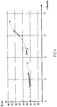
- Figure 4 shows the increase in heat loss with progressive damage to a furnace roller 1.
- the reel condition is recorded according to the proposed procedure and the reel is expanded for repair or replacement when a critical condition is reached.
- a sensor system is required which, in addition to the cooling water temperatures on the inlet and outlet side of the individual roller or roller groups, also measures the cooling water throughput, e.g. B. in kg / s determined.
- Additional measures that improve the present proposal are supplementary, suitable sensor and control units that communicate with the process models and / or process planning models for the purpose of monitoring and regulating the roles.
- This includes, for example, a speed measurement, which regulates the slippage between the slab and roller by comparing it with the slab transport speed and can thus improve both the service life of the roller and the surface quality of the slab underside.
- the slab transport speed is determined using a measuring method that is independent of the transport rollers (rollers), for example using a laser measurement, and compared with the peripheral speed on the surface of the individual furnace rollers. Different states can be set, such as B. higher, same, lower or opposite slab and peripheral speed of individual rollers.
- Caking for example scale buildup, can be removed from the surface of the support ring or slab by slippage or the opposite direction of rotation of individual rollers.
- Another measure that improves the invention is the use of the flow measurement to detect water loss, line blockages or interruption of the water supply.
Landscapes
- Engineering & Computer Science (AREA)
- Chemical & Material Sciences (AREA)
- Mechanical Engineering (AREA)
- Materials Engineering (AREA)
- Organic Chemistry (AREA)
- General Engineering & Computer Science (AREA)
- Physics & Mathematics (AREA)
- Thermal Sciences (AREA)
- Ceramic Engineering (AREA)
- Heat Treatments In General, Especially Conveying And Cooling (AREA)
Description
- Die Erfindung betrifft ein Verfahren zum Betrieb einer kühlbaren Ofenrolle zum Transport eines Bandes oder einer Bramme durch einen Ofen, umfassend eine um eine Achse drehbar gelagerte Tragachse, auf der eine Anzahl an Tragringen angeordnet ist, wobei im axialen Bereich zwischen zumindest zwei Tragrinnen eine Isolierung angeordnet ist, wobei die Isolierung zumindest teilweise aus einem Fasermaterial besteht, bei dem die Ofenrolle in ihrem Inneren mit einem Kühlmedium durchströmt wird, um die Ofenrolle zu kühlen.
- Konventionelle Ofenrollen haben eine Wasserkühlung, um die Rollen vor zu hohen Temperaturen und damit verbundenem vorzeitigen Versagen zu schützen. Der damit verbundene Wärmeentzug des Ofens wird bei herkömmlichen Rollen über eine Betonisolierung verringert.
- Beispiele hierfür sind in der
EP 0 471 218 A1 , in derEP 0 397 231 A1 , in derWO 2015/181736 A1 , in derEP 1 197 721 B1 , in derDE 2 205 694 A , in derDE 40 22 768 C2 und in derDE 693 13 627 T2 beschrieben. - Eine Ofenrolle der eingangs genannten Art ist weiterhin aus der
EP 0 857 933 A1 bekannt. Ähnliche und andere Lösungen zeigen dieUS 6 678 628 B2 , dieDE 693 13 627 T2 , dieEP 2 317 545 A1 und dieUS 4 991 276 A . - Bei den vorbekannten Lösungen ergibt sich nachteilig ein relativ hoher Energieverbrauch im Ofen, dadurch, dass durch die Kühlung relativ viel Wärme aus dem Ofen ausgetragen wird. Ferner ist das Gewicht der Ofenrollen relativ hoch.
- Der Erfindung liegt daher die Auf gabe zugrunde, Maßnahmen vorzuschlagen, mit denen es in einfacherer Weise möglich ist, den Zustand der Ofenrolle zu beurteilen und so eine effektive vorbeugende Instandhaltung installieren zu können.
- Die Lösu n g dieser Aufgabe durch die Erfindung ist dadurch gekennzeichnet, dass erfindungsgemäß die Schritte vorgesehen sind:
- a) Messen der Temperatur (TEinlass) des in die Ofenrolle eintretenden Kühlmediums und Messung der Temperatur (TAuslass) des die Ofenrolle verlassenden Kühlmediums und bilden der Temperaturdifferenz (ΔT = TAuslass - TEinlass);
- b) Messen der Mengenflusses (

- c) Bilden des Produkts aus Temperaturdifferenz (ΔT) und Mengenfluss (

- d) Beobachten des Produkts aus Temperaturdifferenz (ΔT) und Mengenfluss (

- e) Auslösen eines Signals, sobald der Wert des Produkts aus Temperaturdifferenz (ΔT) und Mengenfluss (

- Dabei ist bevorzugt vorgesehen, dass als Grenzwert ein prozentualer Wert eines Durchschnittswerts verwendet wird, der sich während einer vorgegebenen Kalibrierzeit bei einer neu zum Einsatz kommenden Ofenrolle ergibt. Danach wird zunächst eine neu montierte Ofenrolle in der erläuterten Weise überwacht, um einen Referenzwert für das Produkt aus Temperaturdifferenz und Mengenfluss zu erhalten. Dieser Referenzwert wird dann bei der Überwachung zu Grunde gelegt und das Signal beispielsweise dann ausgelöst, wenn der Wert um mindestens 10 % überschritten wird.
- Im Vergleich zu vorbekannten Lösungen erlaubt das vorgeschlagene Konzept eine weitere Verringerung des Wärmeentzugs bei einer Ofenrolle, wozu die genannte Faserisolierung zum Einsatz kommt.
- Neben einer wesentlichen Gewichtsreduktion (bis zu mehr ais 90% des Gewichts einer herkömmlichen Ofenrolle) kann gleichzeitig eine erhebliche Verringerung des Wärmeverlustes pro Rolle erreicht werden; es ist eine ca. 50-prozentige Reduzierung bei Ofentemperaturen von 1.200 °C möglich.
- Im Vergleich zu herkömmlichen Ofenrollen mit Betonisolierung werden insbesondere folgende Vorteile erzielt:
Durch die Faser-Isolierung der Ofenrollen ist eine Verringerung des Energieverbrauchs bei einem üblichen CSP-Ofen bei üblichen Bedingungen um ca. 20 % möglich. - Es sind Einsatztemperaturen bis über 1.250 °C durch Einsatz von Tragringen aus hochtemperaturbeständigem Werkstoff möglich, wobei insbesondere der Werkstoff 60HTR eingesetzt wird.
- Weiterhin ist eine Verbesserung der Oberflächenqualität auf der Brammenunterseite möglich, was sich durch Absenkung der Kontaktpressung zwischen Bramme und Tragringen ergibt. Dazu wird die Anordnung der Tragringe mittels eines Optimierungsprogramms individuell an die Produktionsanforderungen bezüglich Brammenbreite, -länge und -gewicht angepasst. Dieses Rechenprogramm enthält einen Algorithmus, der das Brammengewicht aller auf einer Produktionsanlage gefertigten Abmessungen gleichmäßig auf möglichst viele Tragringe verteilt. Durch einen Versatz (in Förderrichtung) werden Laufspuren aufgrund von Zunderabdruck oder Temperaturstreifigkeit verringert. Wesentliche Bestandteile des Algorithmus sind die Hertz'sche Pressung zur Berechnung des Auflagedrucks auf den Tragringen. Dabei wird auch die Durchbiegung der Rollen berücksichtigt. Die Anordnung des Tragringversatzes wird so ausgelegt, dass auch die jeweils schmalsten und breitesten Brammenabmessungen optimal gestützt werden. Die Tragringanordnung pro Rolle wird periodisch wiederholt. Das später diskutierte Ausführungsbeispiel gemäß
Fig. 3 zeigt beispielsweise zwei Anordnungen, bei denen sich die Tragringanordnung jeweils nach der vierten Rolle wiederholt. - Mit dem vorgeschlagenen Verfahren ist eine vorbeugende Instandhaltung durch Bestimmung und Überwachung des Wärmeentzugs der einzelnen Ofenrollen möglich.
- In der Zeichnung sind Ausführungsbeispiele der Erfindung dargestellt. Es zeigen:
- Fig. 1
- schematisch die Vorderansicht einer wassergekühlten Ofenrolle,
- Fig. 2
- den Verlauf von Wärmeverlusten über der Zeit einer wassergekühlten Ofenrolle, einmal bei einer konventionellen Rolle und einmal bei einer erfindungsgemäßen Rolle,
- Fig. 3a
- in perspektivischer Darstellung vier in Förderrichtung aufeinander folgende Ofenrollen nach einer ersten Ausgestaltung,
- Fig. 3b
- in perspektivischer Darstellung vier in Förderrichtung aufeinander folgende Ofenrollen nach einer zweiten Ausgestaltung und
- Fig. 4
- den Verlauf von Wärmeverlusten über der Zeit, bei der eine fortschreitende Schädigung der Ofenrolle mit der Zeit erkennbar ist.
- In
Figur 1 ist schematisch der Aufbau einer wassergekühlten Ofenrolle 1 zu sehen. Die Ofenrolle 1 weist eine Achse a auf, um die sie drehen kann. Eine Förderrichtung F steht inFigur 1 senkrecht auf der Zeichenebene; in Förderrichtung F wird Gut transportiert, das einen Ofen passiert, in dem die Ofenrolle 1 eingebaut ist. - Die Ofenrolle 1 hat eine zylindrische Tragachse 2 sowie einen zylindrischen Außenumfang 3. Die Tragachse kann sowohl aus einem, vorzugsweise geschmiedeten oder gewalzten, massiven Stabmaterial oder aus einem, vorzugsweise im Schleuderguss hergestellten, Rohr bestehen. Auf der Tragachse 2 mit Außenumfang 3 sind in axialem Abstand mehrere Tragringe 4 angeordnet. Die Tragringe 4 stellen den Kontakt mit dem zu transportierenden Gut her. Zwischen den Tragringen ist das Isoliermaterial 6 angeordnet. Das Isoliermaterial besteht aus einem Fasermaterial, bevorzugt aus Aluminium-Oxid und/oder um Silizium-Oxid.
- In
Figur 1 schematisch angedeutet ist noch eine Mess- und Regelungseinrichtung 5, die die Durchströmung der Ofenrolle 1 mit Kühlwasser sensorisch erfasst und beeinflusst. - Für die Isolierung der Ofenrolle 1 kommt vorliegend eine spezielle Feuerfestwolle, vorzugsweise aus AI- und Si-Oxid, zum Einsatz. Diese Feuerfestwolle wird zu maßgerechten Hohlzylindern vorgefertigt. Beim Zusammenbau der Ofenrolle 1 werden die auf den jeweiligen Tragringabstand abgemessenen Feuerfestzylinder über eine Tragachse gesteckt. Anschließend wird der nachfolgende Tragring 4 auf die Tragachse gesteckt, fest an den Feuerfestzylinder gepresst und auf der Tragachse über ein geeignetes Fügeverfahren, insbesondere Schweißen, fixiert.
- Im Vergleich zum konventionellen Beton als Material für die Isolierung 6 ist das Gewicht der Ofenrolle 1 durch die genannte Ausgestaltung nunmehr deutlich reduziert. Weiterhin wird der Zusammenbau der Ofenrolle durch die Baukastenweise vereinfacht. Durch den Wegfall von Aushärtezeiten erfolgt der Zusammenbau schneller. Durch die besseren Isoliereigenschaften wird der Energieentzug des Ofens deutlich reduziert.
- In
Figur 2 ist ein Beispiel für den Verlauf der Wärmeverluste wassergekühlter Ofenrollen mit Betonisolierung nach dem Stand der Technik (siehe hierzu den oberen Bereich der konventionellen Rolle mit Betonisolierung) und für die erfindungsgemäße Faserisolierung der Ofenrolle (siehe hierzu den unteren Bereich der Rolle mit Faserisolierung) dargestellt. - Die Tragringe 4 können aus einer handelsüblichen Legierung, insbesondere des Typs 2.4879 (DIN 1736), bestehen, vorzugsweise bestehen sie aber aus einer hochtemperatur- und korrosionsbeständigen Legierung, wie z. B. 60HTR. Solche Werkstoffe können herstellungsbedingt nur im Schleudergussverfahren verarbeitet werden. Von einem so hergestellten Rohr werden Scheiben abgeschnitten, die dann jeweils zu Tragringen 4 weiterverarbeitet werden. Mit den genannten Tragringlegierungen kann der mechanische, chemische und thermische Verschleiß der Tragringe 4 bei bestehenden Tunnelöfen sowie bei Tunnelöfen der nächsten Generation mit höheren Heiztemperaturen weiter verringert werden.
- Zur Verbesserung der Oberflächenqualität auf der Brammenunterseite kann das optimale Ofenrollendesign mit einem Auslegungsprogramm bestimmt werden. Betrachtet werden dazu mehrere im Tunnelofen hintereinander angeordnete Ofenrollen 1 mit einer frei definierbaren Anzahl an Tragringen 4, auf denen eine Dünnbramme in beliebiger Breite und Dicke liegt. Über die Anzahl der belasteten Tragringe 4 wird die Auflagefläche bestimmt. Daraus werden unter Berücksichtigung des Brammengewichts die Kontaktpressungen zwischen Bramme und Tragringen berechnet. Mit Hilfe eines Optimierungsalgorithmus kann dann diejenige Tragringanordnung mit minimaler Kontaktpressung errechnet werden. Dabei werden die produktspezifischen Brammenabmessungen berücksichtigt.
- In
Figur 3 sind hierzu zwei Ausführungsbeispiele dargestellt. Gezeigt sind exemplarisch zwei unterschiedliche Anordnungen der Tragringe 4 auf der Tragachse 2 der Ofenrolle 1. - Wie in
Figur 3a zu sehen ist, folgt auf eine erste Ofenrolle mit ihren entsprechend angeordneten Tragringen 4 in Förderrichtung eine solche, bei der die Tragringe 4 versetzt angeordnet sind. Die weiter folgende Ofenrolle 1 weist ihre Tragringe 4 wiederum an denselben Stellen auf wie die erste Ofenrolle. Die schließlich weiter folgende vierte Ofenrolle hat ihre Tragringe 4 an denselben Stellen wie die zweite Ofenrolle. - Bei der Lösung nach
Figur 3b sind die Lagen der Tragringe 4 verteilt angeordnet, was sich durch die oben erwähnte Berechnung ergab. Hierdurch kann eine optimale Stützung des zu transportierenden Guts erreicht werden. - Somit können also die Tragringe 4 - vorzugsweise gestützt durch ein Rechenprogramm, welches hierfür spezifische Daten liefert - so platziert werden, dass Laufspuren am zu fördernden Gut vermieden werden können.
- Der Zustand der gekühlten Rollen 1 wird gemäß dem vorgeschlagenen Verfahren über den Wärmeentzug der einzelnen Rollen erfasst. Dazu werden an jeder Rolle der Kühlwasserdurchfluss sowie der Temperaturanstieg des Kühlwassers über eine vergleichende Messung der Wassertemperatur auf der Ein- und Auslassseite bestimmt. Der Wärmeentzug entspricht dem Wärmefiuss


- Dabei ist cp Wasser die spezifische Wärmekapazität von Wasser in kJ * kg-1 * K-1.
- Der Wärmeentzug aller Rollen ergibt sich aus folgender Gleichung:

- Dabei sind:


ηf der feuerungstechnische Wirkungsgrad und
n die Anzahl der Rollen im Ofen. - Der mittlere erwartete Wärmeentzug einer Rolle wird über die folgende Gleichung bestimmt:

- Die Werte für


- In
Figur 2 sind die typischen Wärmeverluste über das Kühlwasser beton- und faserisolierter Ofenrollen dargestellt. Die Kurven weisen über die Zeit leichte Variationen auf, die sich mit unterschiedlichen Ofenfahrweisen erklären lassen. - Verändert sich

- Über die vorhergehenden Methoden hinaus kann der Verbrauch des Ofens über die Lebenszeit beobachtet werden. Dabei ist die Grundgleichung die folgende:





- Für alle Teilenergieströme bis auf den Wert


-
Figur 4 zeigt den Anstieg des Wärmeverlustes bei fortschreitender Schädigung einer Ofenrolle 1. Über das oben genannte Abweichungskriterium
- Zur Erfassung der Wärmeverluste über die Ofenrolle ist eine Sensorik erforderlich, welche neben den Kühlwassertemperaturen auf der Ein- und Auslaufseite der einzelnen Rollen- oder Rollengruppen auch den Kühlwasserdurchsatz, z. B. in kg/s, bestimmt.
- Zusätzliche, den vorliegenden Vorschlag verbessernde Maßnahmen sind ergänzende, geeignete Sensorik- und Regelungseinheiten, die mit den Prozessmodellen und/oder Prozessplanungsmodellen zwecks Überwachung und Regelung der Rollen kommunizieren. Dazu gehören beispielsweise eine Drehzahlmessung, welche über den Abgleich mit der Brammentransportgeschwindigkeit den Schlupf zwischen Bramme und Rolle regelt und damit sowohl die Lebensdauer der Rolle als auch die Oberflächenqualität der Brammenunterseite verbessern kann. Dabei wird die Brammentransportgeschwindigkeit über ein von den Transportrollen (Rollen) unabhängiges Messverfahren, beispielsweise über eine Lasermessung, bestimmt und mit der Umfangsgeschwindigkeit an der Oberfläche der einzelnen Ofenrollen verglichen. Dabei können verschiedene Zustände eingestellt werden wie z. B. höhere, gleiche, niedrigere oder gegenläufige Brammen- und Umfangsgeschwindigkeit einzelner Rollen. Durch Schlupf oder gegenläufige Drehrichtung einzelner Rollen können Aufbackungen, beispielsweise Zunderanhaftungen, von der Tragring- oder Brammenoberfläche entfernt werden. Eine weitere, die Erfindung verbessernde Maßnahme ist die Verwendung der Durchflussmessung zum Erkennen von Wasserverlust, Leitungsverstopfung oder Unterbrechung der Wasserversorgung.
-
- 1
- Ofenrolle
- 2
- Tragachse (Grundkörper)
- 3
- Außenumfang
- 4
- Tragring
- 5
- Mess- und Regelungseinrichtung
- 6
- Isolierung
- a
- Achse
- F
- Förderrichtung
Claims (2)
- Verfahren zum Betrieb einer kühlbaren Ofenrolle (1) zum Transport eines Bandes oder einer Bramme durch einen Ofen, umfassend eine um eine Achse (a) drehbar gelagerte Tragachse (2), auf der eine Anzahl an Tragringen (4) angeordnet ist, wobei im axialen Bereich zwischen zumindest zwei Tragringen (4) eine Isolierung (6) angeordnet ist, wobei die Isolierung (6) zumindest teilweise aus einem Fasermaterial besteht, bei dem die Ofenrolle (1) in ihrem Inneren mit einem Kühlmedium durchströmt wird, um die Ofenrolle (1) zu kühlen,
dadurch gekennzeichnet, dass
das Verfahren die Schritte aufweist:a) Messen der Temperatur (TEinlass) des in die Ofenrolle (1) eintretenden Kühlmediums und Messung der Temperatur (TAuslass) des die Ofenrolle (1) verlassenden Kühlmediums und bilden der Temperaturdifferenz (ΔT = TAuslass - TEinlass);b) Messen der Mengenflusses ( c) Bilden des Produkts aus Temperaturdifferenz (ΔT) und Mengenfluss (
 d) Beobachten des Produkts aus Temperaturdifferenz (ΔT) und Mengenfluss (
 e) Auslösen eines Signals, sobald der Wert des Produkts aus Temperaturdifferenz (ΔT) und Mengenfluss (
- Verfahren nach Anspruch 1, dadurch gekennzeichnet, dass als Grenzwert ein prozentualer Wert eines Durchschnittswerts verwendet wird, der sich während einer vorgegebenen Kalibrierzeit bei einer neu zum Einsatz kommenden Ofenrolle ergibt.
Applications Claiming Priority (3)
| Application Number | Priority Date | Filing Date | Title |
|---|---|---|---|
| DE102016218547 | 2016-09-27 | ||
| DE102017208710.2A DE102017208710A1 (de) | 2016-09-27 | 2017-05-23 | Kühlbare Ofenrolle und Verfahren zum Betrieb einer solchen |
| PCT/EP2017/073072 WO2018059940A1 (de) | 2016-09-27 | 2017-09-14 | Kühlbare ofenrolle und verfahren zum betrieb einer solchen |
Publications (2)
| Publication Number | Publication Date |
|---|---|
| EP3519115A1 EP3519115A1 (de) | 2019-08-07 |
| EP3519115B1 true EP3519115B1 (de) | 2020-11-11 |
Family
ID=61564072
Family Applications (1)
| Application Number | Title | Priority Date | Filing Date |
|---|---|---|---|
| EP17768101.2A Active EP3519115B1 (de) | 2016-09-27 | 2017-09-14 | Verfahren zum betrieb einer kühlbaren ofenrolle |
Country Status (3)
| Country | Link |
|---|---|
| EP (1) | EP3519115B1 (de) |
| DE (1) | DE102017208710A1 (de) |
| WO (1) | WO2018059940A1 (de) |
Families Citing this family (6)
| Publication number | Priority date | Publication date | Assignee | Title |
|---|---|---|---|---|
| MA52615A (fr) * | 2018-05-15 | 2021-03-24 | Saint Gobain | Convoyeur à rouleaux pour transporter une vitre |
| DE102018220216A1 (de) * | 2018-07-30 | 2020-01-30 | Sms Group Gmbh | Rolle für einen Rollenherdofen |
| DE102018219927A1 (de) * | 2018-07-30 | 2020-01-30 | Sms Group Gmbh | Rollenherdofen |
| CN113697364B (zh) * | 2021-09-13 | 2022-12-20 | 宝武集团鄂城钢铁有限公司 | 一种高温耐久性棒材输送辊及其使用方法 |
| CN115893825A (zh) * | 2022-12-30 | 2023-04-04 | 蚌埠中光电科技有限公司 | 一种高端电子浮法玻璃的辊台过渡装置 |
| DE102023108919A1 (de) | 2023-04-06 | 2024-10-10 | Wpx Faserkeramik Gmbh | Ofenrolle zur Verwendung in einer Hochtemperatur-Anlage, Verfahren zur Verkleidung einer Ofenrolle |
Family Cites Families (10)
| Publication number | Priority date | Publication date | Assignee | Title |
|---|---|---|---|---|
| CA959386A (en) | 1971-02-08 | 1974-12-17 | Uss Engineers And Consultants | Heat-treating-furnace roll and method of heat-treating metal strip therewith |
| NL8901148A (nl) | 1989-05-08 | 1990-12-03 | Hoogovens Ind Ceramics | Rol. |
| US4991276A (en) | 1989-07-31 | 1991-02-12 | Bricmanage, Inc. | Flexible conveyance and guidance roller for use in metalworking furnace structures |
| DE4025935A1 (de) | 1990-08-16 | 1992-02-20 | Didier Werke Ag | Rolle fuer einen rollenofen |
| US5230618A (en) | 1992-02-24 | 1993-07-27 | Bricmanage, Inc. | Insulated furnace roller |
| JP3366544B2 (ja) * | 1997-02-05 | 2003-01-14 | 株式会社クボタ | スラブ搬送用ローラ |
| DE10047046A1 (de) | 2000-09-22 | 2002-04-11 | Sms Demag Ag | Kühlbare Ofenrolle, insbesondere für einen Rollenherdofen |
| US6678628B2 (en) * | 2002-01-14 | 2004-01-13 | William J. Ryan | Apparatus and methods for monitoring and testing coolant recirculation systems |
| EP2317545A1 (de) * | 2009-10-30 | 2011-05-04 | Applied Materials, Inc. | Substrattransportsystem und -verfahren |
| US9796017B2 (en) | 2014-05-27 | 2017-10-24 | Danieli & C. Officine Meccaniche S.P.A. | Roll for handling a load in a furnace usable in a continuous casting and rolling process for thin carbon steel slabs |
-
2017
- 2017-05-23 DE DE102017208710.2A patent/DE102017208710A1/de not_active Withdrawn
- 2017-09-14 WO PCT/EP2017/073072 patent/WO2018059940A1/de not_active Ceased
- 2017-09-14 EP EP17768101.2A patent/EP3519115B1/de active Active
Non-Patent Citations (1)
| Title |
|---|
| None * |
Also Published As
| Publication number | Publication date |
|---|---|
| EP3519115A1 (de) | 2019-08-07 |
| DE102017208710A1 (de) | 2018-03-29 |
| WO2018059940A1 (de) | 2018-04-05 |
Similar Documents
| Publication | Publication Date | Title |
|---|---|---|
| EP3519115A1 (de) | Kühlbare ofenrolle und verfahren zum betrieb einer solchen | |
| DE3036997A1 (de) | Verfahren zur steuerung und regelung der temperatur eines werkstueckes waehrend des walzens in einem warmbandwalzwerk | |
| WO2002024355A1 (de) | Verfahren und anlage zum herstellen von bändern und blechen aus stahl | |
| DE2059977A1 (de) | Verfahren und Vorrichtung zur Regelung eines Brammen-Nachwaermofens | |
| EP2464469A2 (de) | Vorrichtung und verfahren zum herstellen eines dünnen warmbandes | |
| EP1982134A1 (de) | Rollenherdofen zum aufheizen und/oder temperaturausgleichen von stranggiessprodukten aus stahl oder stahllegierungen und dessen anordnung vor einer warmband-fertigwalzstrasse | |
| EP2603332A1 (de) | Ermittlungsverfahren für steuergrössen einer walzstrasse mit mehreren walzgerüsten zum walzen eines metallbandes | |
| EP1824617B1 (de) | Verfahren zum giess-walzen mit erhöhter giessgeschwindigkeit und daran anschliessendem warmwalzen von relativ dünnen metall-, insbesondere stahlwerkstoff-strängen, und giess-walz-einrichtung | |
| EP2828012A1 (de) | Verfahren zur bearbeitung von walzgut und walzwerk | |
| EP3016762B1 (de) | Giesswalzanlage und verfahren zum herstellen von metallischem walzgut | |
| WO2023186471A1 (de) | GIEßWALZANLAGE UND VERFAHREN ZU DEREN BETRIEB | |
| DE102017113358B4 (de) | Feuerverzinkungsvorrichtung sowie Feuerverzinkungsverfahren | |
| DE102010022003A1 (de) | Vertikal-Stranggießanlage | |
| DE102011075627B4 (de) | Sekundärkühleinrichtung zum Kühlen eines Metallstrangs und Verfahren zum Betreiben der Sekundärkühleinrichtung | |
| EP1743050A2 (de) | Verfahren und vorrichtung zur thermischen vakuumbeschichtung | |
| WO2015028370A1 (de) | Verfahren und vorrichtung zum temperieren von walzen | |
| DE102005047432A1 (de) | Rollenofen; Wärmestrahlungssensor und Anlage zur Wärmebehandlung von Flachglas | |
| WO2015018673A1 (de) | Nutzung der in einem kühlfluid enthaltenen wärme | |
| WO2020193051A1 (de) | Ermittlung einer anstellung eines walzgerüsts | |
| WO2020224983A1 (de) | Verfahren zur wärmebehandlung eines metallischen produkts | |
| EP4433235B1 (de) | Vorrichtung und verfahren zur herstellung eines gewalzten metallbandes | |
| DE10104032A1 (de) | Lageranordnung für Hochtemperatur-Anwendungen | |
| WO2012113629A1 (de) | Vorrichtung und verfahren zur kontrolle einer hüttenmännischen anlage | |
| DE2902825C2 (de) | Walze für Warmgut, insbesondere Stütz- und/oder Transportwalze für Stahl-Gießstränge | |
| EP2508828B1 (de) | Vorrichtung und Verfahren zum Erwärmen von Metallbolzen |
Legal Events
| Date | Code | Title | Description |
|---|---|---|---|
| STAA | Information on the status of an ep patent application or granted ep patent |
Free format text: STATUS: UNKNOWN |
|
| STAA | Information on the status of an ep patent application or granted ep patent |
Free format text: STATUS: THE INTERNATIONAL PUBLICATION HAS BEEN MADE |
|
| PUAI | Public reference made under article 153(3) epc to a published international application that has entered the european phase |
Free format text: ORIGINAL CODE: 0009012 |
|
| STAA | Information on the status of an ep patent application or granted ep patent |
Free format text: STATUS: REQUEST FOR EXAMINATION WAS MADE |
|
| 17P | Request for examination filed |
Effective date: 20190429 |
|
| AK | Designated contracting states |
Kind code of ref document: A1 Designated state(s): AL AT BE BG CH CY CZ DE DK EE ES FI FR GB GR HR HU IE IS IT LI LT LU LV MC MK MT NL NO PL PT RO RS SE SI SK SM TR |
|
| AX | Request for extension of the european patent |
Extension state: BA ME |
|
| DAV | Request for validation of the european patent (deleted) | ||
| DAX | Request for extension of the european patent (deleted) | ||
| GRAP | Despatch of communication of intention to grant a patent |
Free format text: ORIGINAL CODE: EPIDOSNIGR1 |
|
| STAA | Information on the status of an ep patent application or granted ep patent |
Free format text: STATUS: GRANT OF PATENT IS INTENDED |
|
| INTG | Intention to grant announced |
Effective date: 20200320 |
|
| GRAJ | Information related to disapproval of communication of intention to grant by the applicant or resumption of examination proceedings by the epo deleted |
Free format text: ORIGINAL CODE: EPIDOSDIGR1 |
|
| STAA | Information on the status of an ep patent application or granted ep patent |
Free format text: STATUS: REQUEST FOR EXAMINATION WAS MADE |
|
| GRAP | Despatch of communication of intention to grant a patent |
Free format text: ORIGINAL CODE: EPIDOSNIGR1 |
|
| STAA | Information on the status of an ep patent application or granted ep patent |
Free format text: STATUS: GRANT OF PATENT IS INTENDED |
|
| INTC | Intention to grant announced (deleted) | ||
| GRAS | Grant fee paid |
Free format text: ORIGINAL CODE: EPIDOSNIGR3 |
|
| INTG | Intention to grant announced |
Effective date: 20200812 |
|
| GRAA | (expected) grant |
Free format text: ORIGINAL CODE: 0009210 |
|
| STAA | Information on the status of an ep patent application or granted ep patent |
Free format text: STATUS: THE PATENT HAS BEEN GRANTED |
|
| AK | Designated contracting states |
Kind code of ref document: B1 Designated state(s): AL AT BE BG CH CY CZ DE DK EE ES FI FR GB GR HR HU IE IS IT LI LT LU LV MC MK MT NL NO PL PT RO RS SE SI SK SM TR |
|
| REG | Reference to a national code |
Ref country code: GB Ref legal event code: FG4D Free format text: NOT ENGLISH |
|
| REG | Reference to a national code |
Ref country code: CH Ref legal event code: EP |
|
| REG | Reference to a national code |
Ref country code: AT Ref legal event code: REF Ref document number: 1332955 Country of ref document: AT Kind code of ref document: T Effective date: 20201115 |
|
| REG | Reference to a national code |
Ref country code: DE Ref legal event code: R096 Ref document number: 502017008182 Country of ref document: DE |
|
| REG | Reference to a national code |
Ref country code: IE Ref legal event code: FG4D Free format text: LANGUAGE OF EP DOCUMENT: GERMAN |
|
| REG | Reference to a national code |
Ref country code: NL Ref legal event code: MP Effective date: 20201111 |
|
| PG25 | Lapsed in a contracting state [announced via postgrant information from national office to epo] |
Ref country code: NO Free format text: LAPSE BECAUSE OF FAILURE TO SUBMIT A TRANSLATION OF THE DESCRIPTION OR TO PAY THE FEE WITHIN THE PRESCRIBED TIME-LIMIT Effective date: 20210211 Ref country code: PT Free format text: LAPSE BECAUSE OF FAILURE TO SUBMIT A TRANSLATION OF THE DESCRIPTION OR TO PAY THE FEE WITHIN THE PRESCRIBED TIME-LIMIT Effective date: 20210311 Ref country code: RS Free format text: LAPSE BECAUSE OF FAILURE TO SUBMIT A TRANSLATION OF THE DESCRIPTION OR TO PAY THE FEE WITHIN THE PRESCRIBED TIME-LIMIT Effective date: 20201111 Ref country code: FI Free format text: LAPSE BECAUSE OF FAILURE TO SUBMIT A TRANSLATION OF THE DESCRIPTION OR TO PAY THE FEE WITHIN THE PRESCRIBED TIME-LIMIT Effective date: 20201111 Ref country code: GR Free format text: LAPSE BECAUSE OF FAILURE TO SUBMIT A TRANSLATION OF THE DESCRIPTION OR TO PAY THE FEE WITHIN THE PRESCRIBED TIME-LIMIT Effective date: 20210212 |
|
| PG25 | Lapsed in a contracting state [announced via postgrant information from national office to epo] |
Ref country code: BG Free format text: LAPSE BECAUSE OF FAILURE TO SUBMIT A TRANSLATION OF THE DESCRIPTION OR TO PAY THE FEE WITHIN THE PRESCRIBED TIME-LIMIT Effective date: 20210211 Ref country code: PL Free format text: LAPSE BECAUSE OF FAILURE TO SUBMIT A TRANSLATION OF THE DESCRIPTION OR TO PAY THE FEE WITHIN THE PRESCRIBED TIME-LIMIT Effective date: 20201111 Ref country code: LV Free format text: LAPSE BECAUSE OF FAILURE TO SUBMIT A TRANSLATION OF THE DESCRIPTION OR TO PAY THE FEE WITHIN THE PRESCRIBED TIME-LIMIT Effective date: 20201111 Ref country code: IS Free format text: LAPSE BECAUSE OF FAILURE TO SUBMIT A TRANSLATION OF THE DESCRIPTION OR TO PAY THE FEE WITHIN THE PRESCRIBED TIME-LIMIT Effective date: 20210311 Ref country code: SE Free format text: LAPSE BECAUSE OF FAILURE TO SUBMIT A TRANSLATION OF THE DESCRIPTION OR TO PAY THE FEE WITHIN THE PRESCRIBED TIME-LIMIT Effective date: 20201111 |
|
| REG | Reference to a national code |
Ref country code: LT Ref legal event code: MG9D |
|
| PG25 | Lapsed in a contracting state [announced via postgrant information from national office to epo] |
Ref country code: HR Free format text: LAPSE BECAUSE OF FAILURE TO SUBMIT A TRANSLATION OF THE DESCRIPTION OR TO PAY THE FEE WITHIN THE PRESCRIBED TIME-LIMIT Effective date: 20201111 |
|
| PG25 | Lapsed in a contracting state [announced via postgrant information from national office to epo] |
Ref country code: RO Free format text: LAPSE BECAUSE OF FAILURE TO SUBMIT A TRANSLATION OF THE DESCRIPTION OR TO PAY THE FEE WITHIN THE PRESCRIBED TIME-LIMIT Effective date: 20201111 Ref country code: SK Free format text: LAPSE BECAUSE OF FAILURE TO SUBMIT A TRANSLATION OF THE DESCRIPTION OR TO PAY THE FEE WITHIN THE PRESCRIBED TIME-LIMIT Effective date: 20201111 Ref country code: SM Free format text: LAPSE BECAUSE OF FAILURE TO SUBMIT A TRANSLATION OF THE DESCRIPTION OR TO PAY THE FEE WITHIN THE PRESCRIBED TIME-LIMIT Effective date: 20201111 Ref country code: LT Free format text: LAPSE BECAUSE OF FAILURE TO SUBMIT A TRANSLATION OF THE DESCRIPTION OR TO PAY THE FEE WITHIN THE PRESCRIBED TIME-LIMIT Effective date: 20201111 Ref country code: CZ Free format text: LAPSE BECAUSE OF FAILURE TO SUBMIT A TRANSLATION OF THE DESCRIPTION OR TO PAY THE FEE WITHIN THE PRESCRIBED TIME-LIMIT Effective date: 20201111 Ref country code: EE Free format text: LAPSE BECAUSE OF FAILURE TO SUBMIT A TRANSLATION OF THE DESCRIPTION OR TO PAY THE FEE WITHIN THE PRESCRIBED TIME-LIMIT Effective date: 20201111 |
|
| REG | Reference to a national code |
Ref country code: DE Ref legal event code: R097 Ref document number: 502017008182 Country of ref document: DE |
|
| PG25 | Lapsed in a contracting state [announced via postgrant information from national office to epo] |
Ref country code: DK Free format text: LAPSE BECAUSE OF FAILURE TO SUBMIT A TRANSLATION OF THE DESCRIPTION OR TO PAY THE FEE WITHIN THE PRESCRIBED TIME-LIMIT Effective date: 20201111 |
|
| PLBE | No opposition filed within time limit |
Free format text: ORIGINAL CODE: 0009261 |
|
| STAA | Information on the status of an ep patent application or granted ep patent |
Free format text: STATUS: NO OPPOSITION FILED WITHIN TIME LIMIT |
|
| 26N | No opposition filed |
Effective date: 20210812 |
|
| PG25 | Lapsed in a contracting state [announced via postgrant information from national office to epo] |
Ref country code: NL Free format text: LAPSE BECAUSE OF FAILURE TO SUBMIT A TRANSLATION OF THE DESCRIPTION OR TO PAY THE FEE WITHIN THE PRESCRIBED TIME-LIMIT Effective date: 20201111 Ref country code: AL Free format text: LAPSE BECAUSE OF FAILURE TO SUBMIT A TRANSLATION OF THE DESCRIPTION OR TO PAY THE FEE WITHIN THE PRESCRIBED TIME-LIMIT Effective date: 20201111 Ref country code: IT Free format text: LAPSE BECAUSE OF FAILURE TO SUBMIT A TRANSLATION OF THE DESCRIPTION OR TO PAY THE FEE WITHIN THE PRESCRIBED TIME-LIMIT Effective date: 20201111 |
|
| PG25 | Lapsed in a contracting state [announced via postgrant information from national office to epo] |
Ref country code: SI Free format text: LAPSE BECAUSE OF FAILURE TO SUBMIT A TRANSLATION OF THE DESCRIPTION OR TO PAY THE FEE WITHIN THE PRESCRIBED TIME-LIMIT Effective date: 20201111 |
|
| PG25 | Lapsed in a contracting state [announced via postgrant information from national office to epo] |
Ref country code: ES Free format text: LAPSE BECAUSE OF FAILURE TO SUBMIT A TRANSLATION OF THE DESCRIPTION OR TO PAY THE FEE WITHIN THE PRESCRIBED TIME-LIMIT Effective date: 20201111 |
|
| REG | Reference to a national code |
Ref country code: CH Ref legal event code: PL |
|
| REG | Reference to a national code |
Ref country code: BE Ref legal event code: MM Effective date: 20210930 |
|
| GBPC | Gb: european patent ceased through non-payment of renewal fee |
Effective date: 20210914 |
|
| PG25 | Lapsed in a contracting state [announced via postgrant information from national office to epo] |
Ref country code: IS Free format text: LAPSE BECAUSE OF FAILURE TO SUBMIT A TRANSLATION OF THE DESCRIPTION OR TO PAY THE FEE WITHIN THE PRESCRIBED TIME-LIMIT Effective date: 20210311 Ref country code: MC Free format text: LAPSE BECAUSE OF FAILURE TO SUBMIT A TRANSLATION OF THE DESCRIPTION OR TO PAY THE FEE WITHIN THE PRESCRIBED TIME-LIMIT Effective date: 20201111 |
|
| PG25 | Lapsed in a contracting state [announced via postgrant information from national office to epo] |
Ref country code: LU Free format text: LAPSE BECAUSE OF NON-PAYMENT OF DUE FEES Effective date: 20210914 Ref country code: IE Free format text: LAPSE BECAUSE OF NON-PAYMENT OF DUE FEES Effective date: 20210914 Ref country code: GB Free format text: LAPSE BECAUSE OF NON-PAYMENT OF DUE FEES Effective date: 20210914 Ref country code: FR Free format text: LAPSE BECAUSE OF NON-PAYMENT OF DUE FEES Effective date: 20210930 Ref country code: BE Free format text: LAPSE BECAUSE OF NON-PAYMENT OF DUE FEES Effective date: 20210930 |
|
| PG25 | Lapsed in a contracting state [announced via postgrant information from national office to epo] |
Ref country code: LI Free format text: LAPSE BECAUSE OF NON-PAYMENT OF DUE FEES Effective date: 20210930 Ref country code: CH Free format text: LAPSE BECAUSE OF NON-PAYMENT OF DUE FEES Effective date: 20210930 |
|
| PG25 | Lapsed in a contracting state [announced via postgrant information from national office to epo] |
Ref country code: CY Free format text: LAPSE BECAUSE OF FAILURE TO SUBMIT A TRANSLATION OF THE DESCRIPTION OR TO PAY THE FEE WITHIN THE PRESCRIBED TIME-LIMIT Effective date: 20201111 |
|
| PG25 | Lapsed in a contracting state [announced via postgrant information from national office to epo] |
Ref country code: HU Free format text: LAPSE BECAUSE OF FAILURE TO SUBMIT A TRANSLATION OF THE DESCRIPTION OR TO PAY THE FEE WITHIN THE PRESCRIBED TIME-LIMIT; INVALID AB INITIO Effective date: 20170914 |
|
| P01 | Opt-out of the competence of the unified patent court (upc) registered |
Effective date: 20230707 |
|
| REG | Reference to a national code |
Ref country code: AT Ref legal event code: MM01 Ref document number: 1332955 Country of ref document: AT Kind code of ref document: T Effective date: 20220914 |
|
| PG25 | Lapsed in a contracting state [announced via postgrant information from national office to epo] |
Ref country code: AT Free format text: LAPSE BECAUSE OF NON-PAYMENT OF DUE FEES Effective date: 20220914 |
|
| PG25 | Lapsed in a contracting state [announced via postgrant information from national office to epo] |
Ref country code: MK Free format text: LAPSE BECAUSE OF FAILURE TO SUBMIT A TRANSLATION OF THE DESCRIPTION OR TO PAY THE FEE WITHIN THE PRESCRIBED TIME-LIMIT Effective date: 20201111 |
|
| PG25 | Lapsed in a contracting state [announced via postgrant information from national office to epo] |
Ref country code: MT Free format text: LAPSE BECAUSE OF FAILURE TO SUBMIT A TRANSLATION OF THE DESCRIPTION OR TO PAY THE FEE WITHIN THE PRESCRIBED TIME-LIMIT Effective date: 20201111 |
|
| PGFP | Annual fee paid to national office [announced via postgrant information from national office to epo] |
Ref country code: DE Payment date: 20240918 Year of fee payment: 8 |
|
| PG25 | Lapsed in a contracting state [announced via postgrant information from national office to epo] |
Ref country code: TR Free format text: LAPSE BECAUSE OF FAILURE TO SUBMIT A TRANSLATION OF THE DESCRIPTION OR TO PAY THE FEE WITHIN THE PRESCRIBED TIME-LIMIT Effective date: 20201111 |