EP3518342A1 - Horn array antenna including dielectric cover - Google Patents
Horn array antenna including dielectric cover Download PDFInfo
- Publication number
- EP3518342A1 EP3518342A1 EP16918934.7A EP16918934A EP3518342A1 EP 3518342 A1 EP3518342 A1 EP 3518342A1 EP 16918934 A EP16918934 A EP 16918934A EP 3518342 A1 EP3518342 A1 EP 3518342A1
- Authority
- EP
- European Patent Office
- Prior art keywords
- horn array
- embossing
- array antenna
- antenna
- horn
- Prior art date
- Legal status (The legal status is an assumption and is not a legal conclusion. Google has not performed a legal analysis and makes no representation as to the accuracy of the status listed.)
- Withdrawn
Links
Images


Classifications
-
- H—ELECTRICITY
- H01—ELECTRIC ELEMENTS
- H01Q—ANTENNAS, i.e. RADIO AERIALS
- H01Q21/00—Antenna arrays or systems
- H01Q21/06—Arrays of individually energised antenna units similarly polarised and spaced apart
- H01Q21/061—Two dimensional planar arrays
- H01Q21/064—Two dimensional planar arrays using horn or slot aerials
-
- H—ELECTRICITY
- H01—ELECTRIC ELEMENTS
- H01Q—ANTENNAS, i.e. RADIO AERIALS
- H01Q13/00—Waveguide horns or mouths; Slot antennas; Leaky-waveguide antennas; Equivalent structures causing radiation along the transmission path of a guided wave
- H01Q13/02—Waveguide horns
-
- H—ELECTRICITY
- H01—ELECTRIC ELEMENTS
- H01Q—ANTENNAS, i.e. RADIO AERIALS
- H01Q15/00—Devices for reflection, refraction, diffraction or polarisation of waves radiated from an antenna, e.g. quasi-optical devices
- H01Q15/02—Refracting or diffracting devices, e.g. lens, prism
- H01Q15/08—Refracting or diffracting devices, e.g. lens, prism formed of solid dielectric material
-
- H—ELECTRICITY
- H01—ELECTRIC ELEMENTS
- H01Q—ANTENNAS, i.e. RADIO AERIALS
- H01Q19/00—Combinations of primary active antenna elements and units with secondary devices, e.g. with quasi-optical devices, for giving the antenna a desired directional characteristic
- H01Q19/06—Combinations of primary active antenna elements and units with secondary devices, e.g. with quasi-optical devices, for giving the antenna a desired directional characteristic using refracting or diffracting devices, e.g. lens
Definitions
- the present invention relates to a horn array antenna, and more particularly, to a horn array antenna including a dielectric cover for reducing a grating lobe.
- An antenna is a device that transmits or receives wireless radio waves in a free space, and is manufactured in various forms and specifications according to the purpose of use thereof.
- An example of the antenna is a horn array antenna.
- FIG. 1 shows one example of the form of a general horn array antenna.
- a horn antenna is a kind of aperture antenna in which a tip of a waveguide (a tubular conductor with an empty center) is formed in a horn shape so that the radio waves may be radiated into space.
- the horn array antenna refers to an antenna in which a plurality of horn antennas as described above are formed in an array on a plane.
- the horn array antenna includes a horn array in which a plurality of horns formed by a plurality of partitions are arranged on a plane, and a radio wave module that transmits or receives radio waves through the horn array.
- a basic structure of such a horn array antenna is disclosed in Korean Patent Laid-Open Publication No. 2012-0014457 ("Horn Array Antenna and Manufacturing Method thereof", 2012. 02. 17).
- An energy distribution of the radio waves radiated from the antenna is generally divided into several directions and each radiation group is called a lobe.
- a lobe in a direction in which radiation energy is maximized is called a main lobe, and the radiation groups in other directions are called side lobes.
- a grating lobe is a special type of signal in the side lobe that appears periodically, and is particularly a signal that appears in the array antenna.
- the side lobe Since a size of the side lobe is significantly smaller than that of the main lobe, noise may be easily removed, but since the grating lobe appears to be significantly strong, the grating lobe is similar in size to the main lobe. Therefore, the grating lobe causes various problems such as causing interference in other equipment, accepting adjacent signals to increase noise, and causing detection errors. Therefore, the development of an array antenna structure for attenuating the grating lobe while reinforcing the main lobe is urgently required.
- the horn array antenna has a problem in that a space is required inside the antenna to dispose a combine circuit and a resonance structure, and a space required for the horn array antenna is increased when the arrangement spacing or the arrangement structure is changed in order to attenuate the grating lobe. That is, the antenna may become thick and large, or efficiency thereof may deteriorate.
- An object of the present invention is to provide a horn array antenna including a dielectric cover for reducing a grating lobe. More specifically, an object of the present invention is to provide a horn array antenna including a dielectric cover, capable of reinforcing a main lobe and effectively attenuating a grating lobe by only further including a dielectric cover in the antenna while not changing an antenna arrangement spacing or an arrangement structure itself in the horn array antenna.
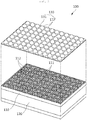
- a horn array antenna 100 including a dielectric cover includes a horn array 110 formed in a form in which a plurality of horns 112 formed by a plurality of partitions 111 are arranged on a plane; an antenna body part 120 provided behind the horn array 110 to transmit or receive radio waves through the horn array 110; and a dielectric cover 130 provided in front of the horn array 110 to refract the radio waves radiated through the horn array 110 to attenuate grating lobes, and formed in a form in which a plurality of embossing cells 132 that protrude forwardly are arranged on the plate 131.
- the embossing cells 132 may be formed in at least one outer shape selected from a dome shape, a lens shape, a donut shape, and a pyramid shape.
- the embossing cells 132 may be formed so that a cross-sectional thickness of one embossing cell 132 is entirely the same or is different for each region.
- the embossing cells 132 may be disposed so that one horn 112 corresponds to one embossing cell 132, or may be disposed so that a plurality of horns 112 correspond to one embossing cell 132.
- the embossing cells 132 may be formed so that a size of each of the plurality of embossing cells 132 arranged on the plate 131 is entirely the same or is different for each region.
- the embossing cells 132 may be formed so that an outer shape of each of the plurality of embossing cells 132 arranged on the plate 131 is entirely the same or is different for each region.
- the dielectric cover may be formed of at least one material selected from Teflon, polyethylene, polycarbonate, and alkyl benzene sulfonate (ABS).
- the grating lobe may be significantly attenuated by covering the front surface of the horn array antenna with the dielectric cover formed in a forwardly convex shape. More specifically, according to the present invention, the beam intensity of a specific angle in a single cell of the horn array antenna is adjusted by intentionally distorting the radiated radio waves using the property that the radio waves are refracted according to the permittivity. Therefore, ultimately, according to the present invention, when a plurality of such cells are arranged, the beam intensity at a desired angle may be adjusted, and as a result, the side lobe (and the grating lobe, which is a kind of side lobe) may be effectively suppressed.
- FIG. 2 shows a horn array antenna 100 including a dielectric cover according to the present invention.
- the horn array antenna 100 according to the present invention basically includes a horn array 110 and an antenna body part 120 similarly to the conventional horn array antenna shown in FIG. 1 , and further includes a dielectric cover 130. A description of each part will be provided below.
- the horn array 110 is formed in the form in which a plurality of horns 112 formed by a plurality of partitions 111 are arranged on a plane as shown.
- a horn antenna is a kind of aperture antenna in which a tip of a waveguide is formed in horn shape so that radio waves may be radiated into space, and the horn array antenna is formed by arranging a plurality of such horn antennas.
- the antenna body part 120 is provided behind the horn array 110 to transmit or receive the radio waves through the horn array 110. That is, the antenna body part 120 includes a module capable of transmitting or receiving the radio waves. Depending on the purpose of use of the horn array antenna 100, the antenna body part 120 may be variously modified such as having only a transmitting module, only a receiving module, or both the transmitting and receiving modules.
- the conventional horn array antenna basically includes only the horn array 110 and the antenna body part 120.
- various attempts have been made to attenuate side lobes, especially, grating lobes, which degrade antenna performance in the conventional horn array antenna.
- the grating lobes are attenuated by changing an antenna arrangement spacing or an arrangement configuration, and in such a case, there is a problem in that a required space is increased and a volume of the antenna is excessively increased.
- the grating lobe is effectively attenuated by providing the dielectric cover 130 in front of the horn array antenna while not changing the antenna arrangement spacing or the arrangement configuration and leaving them unchanged. Accordingly, the antenna performance may be significantly improved by effectively attenuating the grating lobes while basically solving the problem of unnecessarily increasing the volume of the antenna by changing the antenna arrangement.
- the dielectric cover 130 is provided to the front of the horn array 110 as described above to serve to refract the radio waves radiated through the horn array 110 to attenuate the grating lobes.
- a shape of the dielectric cover 130 will be described in more detail, and as shown in FIG. 2 , the dielectric cover 130 is formed in the form in which a plurality of embossing cells 132 that protrude forwardly are arranged on a plate 131.
- the dielectric cover 130 may be formed of a plastic material such as Teflon, polyethylene, polycarbonate, alkyl benzene sulfonate (ABS), or the like.
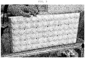
- FIG. 3 shows a photograph of an actual manufacturing example of a dielectric cover according to the present invention.
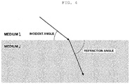
- FIG. 4 illustrates a radio wave refraction principle.
- the radio waves propagating in a space filled with a medium are refracted while a propagation speed thereof changes when permittivity of the medium changes.
- a phenomenon that light refracts in the air as it propagates to the surface, or refracts when passing through a concave lens or a convex lens is also based on such a principle.
- a dielectric lens antenna using a phenomenon in which the radio waves are refracted while passing through a dielectric has been used.
- the dielectric lens antenna is formed in the form in which a dielectric lens is included in a parabolic antenna or a single horn antenna, and FIG. 5 shows an example of a single horn antenna including a dielectric lens.
- Such a conventional dielectric lens antenna has been used for the purpose of increasing a gain as shown in FIG. 5A .
- the beam intensity of a specific angle in a single cell of the horn array antenna is adjusted by intentionally distorting the radiated radio waves unlike the conventional dielectric lens antenna includes the dielectric lens for the purpose of increasing the gain.
- the beam intensity at a desired angle may be ultimately adjusted, and as a result, the side lobe (and the grating lobe, which is a kind of side lobe) may be effectively suppressed. That is, while the conventional dielectric lens has a primary purpose in reinforcing the main lobe, the dielectric cover 130 according to the present invention has a primary purpose in attenuating the side lobe (and the grating lobe).
- the dielectric cover 130 ultimately effectively suppresses the grating lobe by adjusting intensity of the side lobe at the specific angle at the same time of providing no or little loss to the main lobe.
- a performance of the dielectric cover 130 is associated with various factors such as an array type, the number of elements, a frequency of use, permittivity, refraction angle, impedance matching, and reflected waves of peripheral signals.
- a shape of the dielectric cover 130 may also be variously modified according to the various factors.
- examples of various shapes of the dielectric cover 130 will be described in more detail with the drawings.
- FIG. 6 shows various examples of dielectric cover embossing cell form according to the present invention.
- the embossing cell 132 may be formed in a dome shape, a lens shape, a donut shape, a pyramid shape, or the like.
- FIG. 6A shows the dome shape
- FIG. 6B shows the lens shape
- FIG. 6C shows the donut shape
- FIG. 6D shows the pyramid shape, respectively.
- the embossing cell 132 may be formed so that a cross-sectional thickness of one embossing cell 132 is entirely the same or is different for each region.
- the embossing cell 132 may also be formed so that an outer shape of the embossing cell 132 is formed in the dome shape as shown in FIG. 6A and the cross-sectional thickness thereof is entirely the same as shown in the lower left of FIG. 6A , and may also be formed so that the cross-sectional thickness thereof is thick at the central portion and is decreased toward an edge as shown in the lower right of FIG. 6B .
- the embossing cell 132 may also be formed so that the outer shape of the embossing cell 132 is formed in the pyramid shape as shown in FIG. 6D and the cross-sectional thickness thereof is entirely the same as shown in the lower left of FIG. 6D , and may also be formed so that the cross-sectional thickness thereof is thin at the central portion and is increased toward the edge as shown in the lower right of FIG. 6D .
- FIG. 6 various examples of FIG. 6 are to show that although one embossing cell 132 in the present invention has the same shape, the cross-sectional thickness thereof may be variously changed, and the present invention is not limited to such examples.
- the shape of the embossing cell 132 may be variously changed, and the arrangement of the embossing cell 132 may also be variously changed.
- the embossing cells 132 may also be disposed so that one horn 112 corresponds to one embossing cell 132 as shown in FIG. 7A , or may also be disposed so that a plurality of horns 112 correspond to one embossing cell 132 as shown in FIG. 7B.
- FIG. 7B shows an example in which the embossing cells 132 are disposed so that four horns 112 correspond to one embossing cell 132. Meanwhile, although FIG.
- FIG. 7B shows an example in which the four horns 112 corresponding to one embossing cell 132 are arranged in a 2 x 2 array, the embossing cell 132 may elongate to one side and the four horns 112 corresponding to the embossing cell 132 may also be arranged in a 1 x 4 array or a 4 x 1 array, and that is, a correspondence between the embossing cells and the horns may be variously changed depending on the shape and the size of the embossing cells 132.
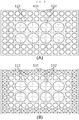
- FIG. 8 shows another example of a dielectric cover embossing cell arrangement according to the present invention.
- the size of each of the plurality of embossing cells 132 arranged on the plate 131 is formed to be entirely the same.
- the size of each of the plurality of embossing cells 132 arranged on the plate 131 is formed to be different for each region.
- the example of FIG. 8 shows that the embossing cell 132 disposed at the central portion of the plate 131 is formed to be large and the embossing cell 132 disposed at the edge of the plate 131 is formed to be small.
- the present invention is not limited thereto, and on the contrary to the example of FIG. 8 , the size of the embossing cell may be formed to be reduced toward the central portion, that is, the size of the embossing cell may be variously changed for each plate region.
- the outer shape of each of the plurality of embossing cells 132 arranged on the plate 131 is formed to be entirely the same.
- the outer shape of each of the plurality of embossing cells 132 arranged on the plate 131 is formed to be different for each region.
- FIG. 8B shows an example in which the embossing cells are formed in large and small dome shapes or lens shapes at a central region and the embossing cells 132 are formed in the pyramid shape at an edge region.
- each of the plurality of embossing cells 132 arranged on the plate 131 is formed to be entirely the same or is formed to be different for each region, i.e., may be variously changed.
- FIG. 9 is an experiment result showing a grating lobe attenuation effect according to a comparison between a conventional horn array antenna and the horn array antenna including the dielectric cover according to the present invention.
- Tables below are experiment results of a case (Table 1) in which the dielectric cover 130 is not present and a case (Table 2) in which the dielectric cover 130 is present, and are numerical representations of some of the results of FIG. 9 .
- the horn array antenna including the dielectric cover according to the present invention may significantly attenuate the grating lobes more effectively than the conventional horn array antenna as shown in FIG. 9 , while the main lobe has little or no change in intensity and there is little or no loss in antenna gain, compared to the conventional horn array antenna.
- the present invention is not limited to the abovementioned embodiments, but may be variously applied.
- the present invention may be variously modified by those skilled in the art to which the present invention pertains without departing from the gist of the present invention claimed in the claims.
- the grating lobe may be significantly attenuated by covering the front surface of the horn array antenna with the dielectric cover formed in a forwardly convex shape.
- the grating lobe since there is no need for complicated signal processing or the like, there is also an advantage in that it is not necessary to configure the signal processing unit in a high specification in constituting the apparatus.
Abstract
Description
- The present invention relates to a horn array antenna, and more particularly, to a horn array antenna including a dielectric cover for reducing a grating lobe.
- An antenna is a device that transmits or receives wireless radio waves in a free space, and is manufactured in various forms and specifications according to the purpose of use thereof. An example of the antenna is a horn array antenna.
FIG. 1 shows one example of the form of a general horn array antenna. A horn antenna is a kind of aperture antenna in which a tip of a waveguide (a tubular conductor with an empty center) is formed in a horn shape so that the radio waves may be radiated into space. The horn array antenna refers to an antenna in which a plurality of horn antennas as described above are formed in an array on a plane. That is, the horn array antenna includes a horn array in which a plurality of horns formed by a plurality of partitions are arranged on a plane, and a radio wave module that transmits or receives radio waves through the horn array. A basic structure of such a horn array antenna is disclosed in Korean Patent Laid-Open Publication No.2012-0014457 - An energy distribution of the radio waves radiated from the antenna is generally divided into several directions and each radiation group is called a lobe. A lobe in a direction in which radiation energy is maximized is called a main lobe, and the radiation groups in other directions are called side lobes. Meanwhile, a grating lobe is a special type of signal in the side lobe that appears periodically, and is particularly a signal that appears in the array antenna.
- Since a size of the side lobe is significantly smaller than that of the main lobe, noise may be easily removed, but since the grating lobe appears to be significantly strong, the grating lobe is similar in size to the main lobe. Therefore, the grating lobe causes various problems such as causing interference in other equipment, accepting adjacent signals to increase noise, and causing detection errors. Therefore, the development of an array antenna structure for attenuating the grating lobe while reinforcing the main lobe is urgently required.
- It is known that a location at which the grating lobe appears is determined by an antenna spacing of the array antenna. Therefore, attempts have been made to attenuate the grating lobe by generally changing an arrangement spacing or an arrangement itself of the antennas. However, the horn array antenna has a problem in that a space is required inside the antenna to dispose a combine circuit and a resonance structure, and a space required for the horn array antenna is increased when the arrangement spacing or the arrangement structure is changed in order to attenuate the grating lobe. That is, the antenna may become thick and large, or efficiency thereof may deteriorate.
- As such, as a technology for removing a grating lobe peak while properly maintaining the antenna spacing in the array antenna without excessively widening the antenna spacing, there is Korean Patent Laid-Open Publication No.
2014-0142490 -
- 1. Korean Patent Laid-Open Publication No.
2012-0014457 - 2. Korean Patent Laid-Open Publication No.
2014-0142490 - An object of the present invention is to provide a horn array antenna including a dielectric cover for reducing a grating lobe. More specifically, an object of the present invention is to provide a horn array antenna including a dielectric cover, capable of reinforcing a main lobe and effectively attenuating a grating lobe by only further including a dielectric cover in the antenna while not changing an antenna arrangement spacing or an arrangement structure itself in the horn array antenna.
- In one general aspect, a
horn array antenna 100 including a dielectric cover includes ahorn array 110 formed in a form in which a plurality ofhorns 112 formed by a plurality ofpartitions 111 are arranged on a plane; anantenna body part 120 provided behind thehorn array 110 to transmit or receive radio waves through thehorn array 110; and adielectric cover 130 provided in front of thehorn array 110 to refract the radio waves radiated through thehorn array 110 to attenuate grating lobes, and formed in a form in which a plurality ofembossing cells 132 that protrude forwardly are arranged on theplate 131. - The
embossing cells 132 may be formed in at least one outer shape selected from a dome shape, a lens shape, a donut shape, and a pyramid shape. - The
embossing cells 132 may be formed so that a cross-sectional thickness of oneembossing cell 132 is entirely the same or is different for each region. - The
embossing cells 132 may be disposed so that onehorn 112 corresponds to oneembossing cell 132, or may be disposed so that a plurality ofhorns 112 correspond to oneembossing cell 132. - The
embossing cells 132 may be formed so that a size of each of the plurality ofembossing cells 132 arranged on theplate 131 is entirely the same or is different for each region. - The
embossing cells 132 may be formed so that an outer shape of each of the plurality ofembossing cells 132 arranged on theplate 131 is entirely the same or is different for each region. - The dielectric cover may be formed of at least one material selected from Teflon, polyethylene, polycarbonate, and alkyl benzene sulfonate (ABS).
- According to the present invention, the grating lobe may be significantly attenuated by covering the front surface of the horn array antenna with the dielectric cover formed in a forwardly convex shape. More specifically, according to the present invention, the beam intensity of a specific angle in a single cell of the horn array antenna is adjusted by intentionally distorting the radiated radio waves using the property that the radio waves are refracted according to the permittivity. Therefore, ultimately, according to the present invention, when a plurality of such cells are arranged, the beam intensity at a desired angle may be adjusted, and as a result, the side lobe (and the grating lobe, which is a kind of side lobe) may be effectively suppressed.
- In addition, according to the present invention, since there is no need for complicated signal processing or the like, there is also an advantage in that it is not necessary to configure the signal processing unit in a high specification in constituting the apparatus.
-
-
FIG. 1 is a view showing a general horn array antenna. -
FIG. 2 is a view showing a horn array antenna including a dielectric cover according to the present invention. -
FIG. 3 is a view illustrating an actual manufacturing of a dielectric cover according to the present invention. -
FIG. 4 is a view showing a radio wave refraction principle. -
FIG. 5 is a view illustrating a single horn antenna including a dielectric lens. -
FIG. 6 is a view showing various examples of a dielectric cover embossing cell form according to the present invention. -
FIG. 7 is a view showing various examples of a dielectric cover embossing cell arrangement according to the present invention. -
FIG. 8 is a view showing another example of the dielectric cover embossing cell arrangement according to the present invention. -
FIG. 9 is a view showing a grating lobe attenuation effect according to a comparison between a conventional horn array antenna and the horn array antenna including the dielectric cover according to the present invention. -
- 100: horn array antenna (according to the present invention)
- 110: horn array
- 111: partition 112: horn
- 120: antenna body part
- 130: dielectric cover
- 131: plate 132: embossing cell
- Hereinafter, a horn array antenna including a dielectric cover according to the present invention having the configuration as described above will be described in detail with reference to the accompanying drawings.
-
FIG. 2 shows ahorn array antenna 100 including a dielectric cover according to the present invention. Thehorn array antenna 100 according to the present invention basically includes ahorn array 110 and anantenna body part 120 similarly to the conventional horn array antenna shown inFIG. 1 , and further includes adielectric cover 130. A description of each part will be provided below. - The
horn array 110 is formed in the form in which a plurality ofhorns 112 formed by a plurality ofpartitions 111 are arranged on a plane as shown. As briefly described above, a horn antenna is a kind of aperture antenna in which a tip of a waveguide is formed in horn shape so that radio waves may be radiated into space, and the horn array antenna is formed by arranging a plurality of such horn antennas. - The
antenna body part 120 is provided behind thehorn array 110 to transmit or receive the radio waves through thehorn array 110. That is, theantenna body part 120 includes a module capable of transmitting or receiving the radio waves. Depending on the purpose of use of thehorn array antenna 100, theantenna body part 120 may be variously modified such as having only a transmitting module, only a receiving module, or both the transmitting and receiving modules. - The conventional horn array antenna basically includes only the
horn array 110 and theantenna body part 120. In this case, various attempts have been made to attenuate side lobes, especially, grating lobes, which degrade antenna performance in the conventional horn array antenna. As described above, conventionally, the grating lobes are attenuated by changing an antenna arrangement spacing or an arrangement configuration, and in such a case, there is a problem in that a required space is increased and a volume of the antenna is excessively increased. According to the present invention, in order to solve such a problem, the grating lobe is effectively attenuated by providing thedielectric cover 130 in front of the horn array antenna while not changing the antenna arrangement spacing or the arrangement configuration and leaving them unchanged. Accordingly, the antenna performance may be significantly improved by effectively attenuating the grating lobes while basically solving the problem of unnecessarily increasing the volume of the antenna by changing the antenna arrangement. - The
dielectric cover 130 is provided to the front of thehorn array 110 as described above to serve to refract the radio waves radiated through thehorn array 110 to attenuate the grating lobes. A shape of thedielectric cover 130 will be described in more detail, and as shown inFIG. 2 , thedielectric cover 130 is formed in the form in which a plurality ofembossing cells 132 that protrude forwardly are arranged on aplate 131. In addition, thedielectric cover 130 may be formed of a plastic material such as Teflon, polyethylene, polycarbonate, alkyl benzene sulfonate (ABS), or the like.FIG. 3 shows a photograph of an actual manufacturing example of a dielectric cover according to the present invention. - Hereinafter, a principle of a grating lobe attenuation effect using the
dielectric cover 130 according to the present invention will be described in more detail. -
FIG. 4 illustrates a radio wave refraction principle. The radio waves propagating in a space filled with a medium are refracted while a propagation speed thereof changes when permittivity of the medium changes. A phenomenon that light refracts in the air as it propagates to the surface, or refracts when passing through a concave lens or a convex lens is also based on such a principle. - Conventionally, in the field of antennas, a dielectric lens antenna using a phenomenon in which the radio waves are refracted while passing through a dielectric has been used. The dielectric lens antenna is formed in the form in which a dielectric lens is included in a parabolic antenna or a single horn antenna, and
FIG. 5 shows an example of a single horn antenna including a dielectric lens. Such a conventional dielectric lens antenna has been used for the purpose of increasing a gain as shown inFIG. 5A . - According to the present invention, the beam intensity of a specific angle in a single cell of the horn array antenna is adjusted by intentionally distorting the radiated radio waves unlike the conventional dielectric lens antenna includes the dielectric lens for the purpose of increasing the gain. As a result, according to the present invention, when a plurality of such cells are arranged, the beam intensity at a desired angle may be ultimately adjusted, and as a result, the side lobe (and the grating lobe, which is a kind of side lobe) may be effectively suppressed. That is, while the conventional dielectric lens has a primary purpose in reinforcing the main lobe, the
dielectric cover 130 according to the present invention has a primary purpose in attenuating the side lobe (and the grating lobe). - As such, the
dielectric cover 130 according to the present invention ultimately effectively suppresses the grating lobe by adjusting intensity of the side lobe at the specific angle at the same time of providing no or little loss to the main lobe. In this case, a performance of thedielectric cover 130 is associated with various factors such as an array type, the number of elements, a frequency of use, permittivity, refraction angle, impedance matching, and reflected waves of peripheral signals. A shape of thedielectric cover 130 may also be variously modified according to the various factors. Hereinafter, examples of various shapes of thedielectric cover 130 will be described in more detail with the drawings. -
FIG. 6 shows various examples of dielectric cover embossing cell form according to the present invention. As shown inFIG. 6 , theembossing cell 132 may be formed in a dome shape, a lens shape, a donut shape, a pyramid shape, or the like.FIG. 6A shows the dome shape,FIG. 6B shows the lens shape,FIG. 6C shows the donut shape, andFIG. 6D shows the pyramid shape, respectively. - In addition, the
embossing cell 132 may be formed so that a cross-sectional thickness of oneembossing cell 132 is entirely the same or is different for each region. For example, theembossing cell 132 may also be formed so that an outer shape of theembossing cell 132 is formed in the dome shape as shown inFIG. 6A and the cross-sectional thickness thereof is entirely the same as shown in the lower left ofFIG. 6A , and may also be formed so that the cross-sectional thickness thereof is thick at the central portion and is decreased toward an edge as shown in the lower right ofFIG. 6B . As another example, theembossing cell 132 may also be formed so that the outer shape of theembossing cell 132 is formed in the pyramid shape as shown inFIG. 6D and the cross-sectional thickness thereof is entirely the same as shown in the lower left ofFIG. 6D , and may also be formed so that the cross-sectional thickness thereof is thin at the central portion and is increased toward the edge as shown in the lower right ofFIG. 6D . Of course, various examples ofFIG. 6 are to show that although oneembossing cell 132 in the present invention has the same shape, the cross-sectional thickness thereof may be variously changed, and the present invention is not limited to such examples. - As such, the shape of the
embossing cell 132 may be variously changed, and the arrangement of theembossing cell 132 may also be variously changed. First, theembossing cells 132 may also be disposed so that onehorn 112 corresponds to oneembossing cell 132 as shown inFIG. 7A , or may also be disposed so that a plurality ofhorns 112 correspond to oneembossing cell 132 as shown inFIG. 7B. FIG. 7B shows an example in which theembossing cells 132 are disposed so that fourhorns 112 correspond to oneembossing cell 132. Meanwhile, althoughFIG. 7B shows an example in which the fourhorns 112 corresponding to oneembossing cell 132 are arranged in a 2 x 2 array, theembossing cell 132 may elongate to one side and the fourhorns 112 corresponding to theembossing cell 132 may also be arranged in a 1 x 4 array or a 4 x 1 array, and that is, a correspondence between the embossing cells and the horns may be variously changed depending on the shape and the size of theembossing cells 132. -
FIG. 8 shows another example of a dielectric cover embossing cell arrangement according to the present invention. In the example ofFIG. 7 , the size of each of the plurality ofembossing cells 132 arranged on theplate 131 is formed to be entirely the same. On the contrary, in the example ofFIG. 8 , the size of each of the plurality ofembossing cells 132 arranged on theplate 131 is formed to be different for each region. The example ofFIG. 8 shows that theembossing cell 132 disposed at the central portion of theplate 131 is formed to be large and theembossing cell 132 disposed at the edge of theplate 131 is formed to be small. Of course, the present invention is not limited thereto, and on the contrary to the example ofFIG. 8 , the size of the embossing cell may be formed to be reduced toward the central portion, that is, the size of the embossing cell may be variously changed for each plate region. - Meanwhile, in the examples of
FIGS. 7 and8A , the outer shape of each of the plurality ofembossing cells 132 arranged on theplate 131 is formed to be entirely the same. On the contrary, in the example ofFIG. 8B , the outer shape of each of the plurality ofembossing cells 132 arranged on theplate 131 is formed to be different for each region.FIG. 8B shows an example in which the embossing cells are formed in large and small dome shapes or lens shapes at a central region and theembossing cells 132 are formed in the pyramid shape at an edge region. Of course, this is merely an example and the present invention is not limited thereto, and as described above, in the present invention, the outer shape of each of the plurality ofembossing cells 132 arranged on theplate 131 is formed to be entirely the same or is formed to be different for each region, i.e., may be variously changed. -
FIG. 9 is an experiment result showing a grating lobe attenuation effect according to a comparison between a conventional horn array antenna and the horn array antenna including the dielectric cover according to the present invention. In addition, Tables below are experiment results of a case (Table 1) in which thedielectric cover 130 is not present and a case (Table 2) in which thedielectric cover 130 is present, and are numerical representations of some of the results ofFIG. 9 . - As shown in Tables 1 and 2 and can be intuitively seen from the graph of
FIG. 9 , an effect in which the grating lobes (both end portions of the graph) are significantly attenuated exhibits when the dielectric cover is present as compared to when the dielectric cover is not present. In addition, as shown in the graph ofFIG. 9 , it can be seen that the main lobe (the central portion of the graph, the maximum value portion) appears almost the same both when the dielectric cover is not present and when the dielectric cover is present.[Table 1] [Table 2] No cover data Ro=35, Ri=29 H-pol (Port 1) E-plane (Φ=0) H-pol (Port 1) E-plane (Φ=0) 7.9 GHz -8.45 7.9 GHz -11.08 8.15 GHz -7.71 8.15 GHz -9.74 8.4 GHz -7.21 8.4 GHz -7.21 V-pol (Port 2) E-plane (Φ=90) V-pol (Port 2) H-plane (Φ=0) 7.9 GHz -8.16 7.9 GHz -16.36 8.15 GHz -7.4 8.15 GHz -27.95 8.4 GHz -6.98 8.4 GHz -13.21 - As such, it can be seen that the horn array antenna including the dielectric cover according to the present invention may significantly attenuate the grating lobes more effectively than the conventional horn array antenna as shown in
FIG. 9 , while the main lobe has little or no change in intensity and there is little or no loss in antenna gain, compared to the conventional horn array antenna. - The present invention is not limited to the abovementioned embodiments, but may be variously applied. In addition, the present invention may be variously modified by those skilled in the art to which the present invention pertains without departing from the gist of the present invention claimed in the claims.
- According to the present invention, the grating lobe may be significantly attenuated by covering the front surface of the horn array antenna with the dielectric cover formed in a forwardly convex shape. In addition, according to the present invention, since there is no need for complicated signal processing or the like, there is also an advantage in that it is not necessary to configure the signal processing unit in a high specification in constituting the apparatus.
Claims (7)
- A horn array antenna including a dielectric cover, the horn array antenna comprising
a horn array formed in a form in which a plurality of horns formed by a plurality of partitions are arranged on a plane;
an antenna body part provided behind the horn array to transmit or receive radio waves through the horn array; and
a dielectric cover provided in front of the horn array to refract the radio waves radiated through the horn array to attenuate grating lobes, and formed in a form in which a plurality of embossing cells that protrude forwardly are arranged on the plate. - The horn array antenna of claim 1, wherein the embossing cells are formed in at least one outer shape selected from a dome shape, a lens shape, a donut shape, and a pyramid shape.
- The horn array antenna of claim 1, wherein the embossing cells are formed so that a cross-sectional thickness of one embossing cell is entirely the same or is different for each region.
- The horn array antenna of claim 1, wherein the embossing cells are disposed so that one horn corresponds to one embossing cell, or are disposed so that a plurality of horns correspond to one embossing cell.
- The horn array antenna of claim 1, wherein the embossing cells are formed so that a size of each of the plurality of embossing cells arranged on the plate is entirely the same or is different for each region.
- The horn array antenna of claim 1, wherein the embossing cells are formed so that an outer shape of each of the plurality of embossing cells arranged on the plate is entirely the same or is different for each region.
- The horn array antenna of claim 1, wherein the dielectric cover is formed of at least one material selected from Teflon, polyethylene, polycarbonate, and alkyl benzene sulfonate (ABS).
Applications Claiming Priority (2)
| Application Number | Priority Date | Filing Date | Title |
|---|---|---|---|
| KR20160132281 | 2016-10-12 | ||
| PCT/KR2016/011475 WO2018070566A1 (en) | 2016-10-12 | 2016-10-13 | Horn array antenna including dielectric cover |
Publications (2)
| Publication Number | Publication Date |
|---|---|
| EP3518342A1 true EP3518342A1 (en) | 2019-07-31 |
| EP3518342A4 EP3518342A4 (en) | 2020-05-27 |
Family
ID=61905760
Family Applications (1)
| Application Number | Title | Priority Date | Filing Date |
|---|---|---|---|
| EP16918934.7A Withdrawn EP3518342A4 (en) | 2016-10-12 | 2016-10-13 | Horn array antenna including dielectric cover |
Country Status (2)
| Country | Link |
|---|---|
| EP (1) | EP3518342A4 (en) |
| WO (1) | WO2018070566A1 (en) |
Cited By (4)
| Publication number | Priority date | Publication date | Assignee | Title |
|---|---|---|---|---|
| CN113540806A (en) * | 2021-07-21 | 2021-10-22 | 中国电子科技集团公司第三十八研究所 | Integrated terahertz corrugated horn antenna array based on 3D printing and manufacturing method thereof |
| WO2023276606A1 (en) * | 2021-07-02 | 2023-01-05 | 株式会社村田製作所 | Microlens array antenna, and radar device and vehicle having same |
| WO2023008268A1 (en) * | 2021-07-27 | 2023-02-02 | 株式会社村田製作所 | Microlens array antenna, and radar device and vehicle equipped with same |
| EP4172551A4 (en) * | 2020-06-30 | 2024-04-03 | Paneratech Inc | Antenna-grating sensing system |
Families Citing this family (1)
| Publication number | Priority date | Publication date | Assignee | Title |
|---|---|---|---|---|
| US11791565B2 (en) * | 2021-10-11 | 2023-10-17 | Lockheed Martin Corporation | Aperture antenna arrays with aperture mesh |
Family Cites Families (8)
| Publication number | Priority date | Publication date | Assignee | Title |
|---|---|---|---|---|
| JPH0739109U (en) * | 1991-02-14 | 1995-07-14 | 三菱電機株式会社 | Horn cover |
| US6359595B1 (en) * | 2000-04-27 | 2002-03-19 | Nortel Networks Limited | Flat plate antenna |
| CA2496053A1 (en) * | 2002-08-20 | 2004-03-04 | Aerosat Corporation | Communication system with broadband antenna |
| KR100624049B1 (en) * | 2004-04-26 | 2006-09-20 | 주식회사 필셋 | Square Lattice Horn Array Antenna for Circularly Polarized Reception |
| JP2006166399A (en) * | 2004-11-15 | 2006-06-22 | Maspro Denkoh Corp | Antenna system for emc test, test signal generation apparatus and transmission apparatus |
| JP4029217B2 (en) * | 2005-01-20 | 2008-01-09 | 株式会社村田製作所 | Waveguide horn array antenna and radar apparatus |
| KR20120014457A (en) * | 2010-08-09 | 2012-02-17 | 현대모비스 주식회사 | Horn array antenna and the manufacture method thereof |
| JP2012175680A (en) * | 2011-02-24 | 2012-09-10 | Nec Corp | Horn array antenna |
-
2016
- 2016-10-13 WO PCT/KR2016/011475 patent/WO2018070566A1/en unknown
- 2016-10-13 EP EP16918934.7A patent/EP3518342A4/en not_active Withdrawn
Cited By (5)
| Publication number | Priority date | Publication date | Assignee | Title |
|---|---|---|---|---|
| EP4172551A4 (en) * | 2020-06-30 | 2024-04-03 | Paneratech Inc | Antenna-grating sensing system |
| WO2023276606A1 (en) * | 2021-07-02 | 2023-01-05 | 株式会社村田製作所 | Microlens array antenna, and radar device and vehicle having same |
| CN113540806A (en) * | 2021-07-21 | 2021-10-22 | 中国电子科技集团公司第三十八研究所 | Integrated terahertz corrugated horn antenna array based on 3D printing and manufacturing method thereof |
| CN113540806B (en) * | 2021-07-21 | 2023-06-06 | 中国电子科技集团公司第三十八研究所 | Integrated terahertz corrugated horn antenna array based on 3D printing and manufacturing method thereof |
| WO2023008268A1 (en) * | 2021-07-27 | 2023-02-02 | 株式会社村田製作所 | Microlens array antenna, and radar device and vehicle equipped with same |
Also Published As
| Publication number | Publication date |
|---|---|
| EP3518342A4 (en) | 2020-05-27 |
| WO2018070566A1 (en) | 2018-04-19 |
Similar Documents
| Publication | Publication Date | Title |
|---|---|---|
| EP3518342A1 (en) | Horn array antenna including dielectric cover | |
| KR102110329B1 (en) | Antenna and radar system including polarization-rotation layer | |
| CN106532274B (en) | Dual-frequency circularly polarized planar reflective array antenna based on split ring metamaterial unit | |
| US3231892A (en) | Antenna feed system simultaneously operable at two frequencies utilizing polarization independent frequency selective intermediate reflector | |
| KR101405283B1 (en) | Planar horn array antenna | |
| CN110336137B (en) | Impedance matching high-gain lens antenna and design method thereof | |
| Legay et al. | Multiple beam antenna based on a parallel plate waveguide continuous delay lens beamformer | |
| US11374311B2 (en) | Millimeter-wave radar cover | |
| Pourahmadazar et al. | A millimeter-wave fresnel zone plate lens design using perforated 3D printing material | |
| CN110739548B (en) | High-gain low-profile transmissive array antenna | |
| CN111052507B (en) | Antenna and wireless device | |
| CN111262044A (en) | Cylindrical luneberg lens antenna and cylindrical luneberg lens antenna array | |
| KR100964623B1 (en) | Waveguide slot array antenna and planar slot array antenna | |
| JP6314732B2 (en) | Wireless communication module | |
| CN209822868U (en) | Antenna with plane lens | |
| WO2021168846A1 (en) | Radome and detection device | |
| KR101508074B1 (en) | Frequency selective surface using patch | |
| JP4027775B2 (en) | Slot array antenna | |
| GB2182806A (en) | Linearly polarized grid reflector antenna system with improved cross-polarization performance | |
| US11870148B2 (en) | Planar metal Fresnel millimeter-wave lens | |
| KR102120455B1 (en) | Automotive Radar Antenna with Wide Angle Characteristics | |
| CN115117637B (en) | Dual-polarized absorption integrated graphene frequency selective composite super-structure surface and radome | |
| RU2278453C1 (en) | Radar antenna of reduced effective dissipation area | |
| Zhu et al. | MM-wave cylindrical dielectric lens antenna for full azimuth scanning coverage | |
| CN108539437B (en) | Dual-frequency dual-polarization common-caliber waveguide slot array antenna |
Legal Events
| Date | Code | Title | Description |
|---|---|---|---|
| PUAI | Public reference made under article 153(3) epc to a published international application that has entered the european phase |
Free format text: ORIGINAL CODE: 0009012 |
|
| STAA | Information on the status of an ep patent application or granted ep patent |
Free format text: STATUS: REQUEST FOR EXAMINATION WAS MADE |
|
| 17P | Request for examination filed |
Effective date: 20190424 |
|
| AK | Designated contracting states |
Kind code of ref document: A1 Designated state(s): AL AT BE BG CH CY CZ DE DK EE ES FI FR GB GR HR HU IE IS IT LI LT LU LV MC MK MT NL NO PL PT RO RS SE SI SK SM TR |
|
| AX | Request for extension of the european patent |
Extension state: BA ME |
|
| RIN1 | Information on inventor provided before grant (corrected) |
Inventor name: PARK, CHANGOO Inventor name: LEE, JUNHEE Inventor name: YANG, SUNGEUN |
|
| DAV | Request for validation of the european patent (deleted) | ||
| DAX | Request for extension of the european patent (deleted) | ||
| A4 | Supplementary search report drawn up and despatched |
Effective date: 20200428 |
|
| RIC1 | Information provided on ipc code assigned before grant |
Ipc: H01Q 13/02 20060101ALI20200421BHEP Ipc: H01Q 21/06 20060101ALI20200421BHEP Ipc: H01Q 15/08 20060101AFI20200421BHEP Ipc: H01Q 19/06 20060101ALI20200421BHEP |
|
| STAA | Information on the status of an ep patent application or granted ep patent |
Free format text: STATUS: THE APPLICATION IS DEEMED TO BE WITHDRAWN |
|
| 18D | Application deemed to be withdrawn |
Effective date: 20201126 |