EP3517977B1 - Magnetic gas turbine sensor - Google Patents
Magnetic gas turbine sensor Download PDFInfo
- Publication number
- EP3517977B1 EP3517977B1 EP19150844.9A EP19150844A EP3517977B1 EP 3517977 B1 EP3517977 B1 EP 3517977B1 EP 19150844 A EP19150844 A EP 19150844A EP 3517977 B1 EP3517977 B1 EP 3517977B1
- Authority
- EP
- European Patent Office
- Prior art keywords
- sensor
- fluid
- pole piece
- fluid conduit
- magnet
- Prior art date
- Legal status (The legal status is an assumption and is not a legal conclusion. Google has not performed a legal analysis and makes no representation as to the accuracy of the status listed.)
- Active
Links
Images


Classifications
-
- G—PHYSICS
- G01—MEASURING; TESTING
- G01M—TESTING STATIC OR DYNAMIC BALANCE OF MACHINES OR STRUCTURES; TESTING OF STRUCTURES OR APPARATUS, NOT OTHERWISE PROVIDED FOR
- G01M15/00—Testing of engines
- G01M15/14—Testing gas-turbine engines or jet-propulsion engines
-
- G—PHYSICS
- G01—MEASURING; TESTING
- G01P—MEASURING LINEAR OR ANGULAR SPEED, ACCELERATION, DECELERATION, OR SHOCK; INDICATING PRESENCE, ABSENCE, OR DIRECTION, OF MOVEMENT
- G01P3/00—Measuring linear or angular speed; Measuring differences of linear or angular speeds
- G01P3/42—Devices characterised by the use of electric or magnetic means
- G01P3/44—Devices characterised by the use of electric or magnetic means for measuring angular speed
-
- G—PHYSICS
- G01—MEASURING; TESTING
- G01P—MEASURING LINEAR OR ANGULAR SPEED, ACCELERATION, DECELERATION, OR SHOCK; INDICATING PRESENCE, ABSENCE, OR DIRECTION, OF MOVEMENT
- G01P3/00—Measuring linear or angular speed; Measuring differences of linear or angular speeds
- G01P3/42—Devices characterised by the use of electric or magnetic means
- G01P3/44—Devices characterised by the use of electric or magnetic means for measuring angular speed
- G01P3/48—Devices characterised by the use of electric or magnetic means for measuring angular speed by measuring frequency of generated current or voltage
- G01P3/481—Devices characterised by the use of electric or magnetic means for measuring angular speed by measuring frequency of generated current or voltage of pulse signals
- G01P3/488—Devices characterised by the use of electric or magnetic means for measuring angular speed by measuring frequency of generated current or voltage of pulse signals delivered by variable reluctance detectors
-
- G—PHYSICS
- G01—MEASURING; TESTING
- G01L—MEASURING FORCE, STRESS, TORQUE, WORK, MECHANICAL POWER, MECHANICAL EFFICIENCY, OR FLUID PRESSURE
- G01L3/00—Measuring torque, work, mechanical power, or mechanical efficiency, in general
- G01L3/02—Rotary-transmission dynamometers
- G01L3/04—Rotary-transmission dynamometers wherein the torque-transmitting element comprises a torsionally-flexible shaft
- G01L3/10—Rotary-transmission dynamometers wherein the torque-transmitting element comprises a torsionally-flexible shaft involving electric or magnetic means for indicating
- G01L3/101—Rotary-transmission dynamometers wherein the torque-transmitting element comprises a torsionally-flexible shaft involving electric or magnetic means for indicating involving magnetic or electromagnetic means
-
- G—PHYSICS
- G01—MEASURING; TESTING
- G01L—MEASURING FORCE, STRESS, TORQUE, WORK, MECHANICAL POWER, MECHANICAL EFFICIENCY, OR FLUID PRESSURE
- G01L3/00—Measuring torque, work, mechanical power, or mechanical efficiency, in general
- G01L3/02—Rotary-transmission dynamometers
- G01L3/04—Rotary-transmission dynamometers wherein the torque-transmitting element comprises a torsionally-flexible shaft
- G01L3/10—Rotary-transmission dynamometers wherein the torque-transmitting element comprises a torsionally-flexible shaft involving electric or magnetic means for indicating
- G01L3/101—Rotary-transmission dynamometers wherein the torque-transmitting element comprises a torsionally-flexible shaft involving electric or magnetic means for indicating involving magnetic or electromagnetic means
- G01L3/105—Rotary-transmission dynamometers wherein the torque-transmitting element comprises a torsionally-flexible shaft involving electric or magnetic means for indicating involving magnetic or electromagnetic means involving inductive means
-
- G—PHYSICS
- G01—MEASURING; TESTING
- G01L—MEASURING FORCE, STRESS, TORQUE, WORK, MECHANICAL POWER, MECHANICAL EFFICIENCY, OR FLUID PRESSURE
- G01L3/00—Measuring torque, work, mechanical power, or mechanical efficiency, in general
- G01L3/02—Rotary-transmission dynamometers
- G01L3/14—Rotary-transmission dynamometers wherein the torque-transmitting element is other than a torsionally-flexible shaft
-
- G—PHYSICS
- G01—MEASURING; TESTING
- G01P—MEASURING LINEAR OR ANGULAR SPEED, ACCELERATION, DECELERATION, OR SHOCK; INDICATING PRESENCE, ABSENCE, OR DIRECTION, OF MOVEMENT
- G01P1/00—Details of instruments
- G01P1/006—Details of instruments used for thermal compensation
-
- G—PHYSICS
- G01—MEASURING; TESTING
- G01P—MEASURING LINEAR OR ANGULAR SPEED, ACCELERATION, DECELERATION, OR SHOCK; INDICATING PRESENCE, ABSENCE, OR DIRECTION, OF MOVEMENT
- G01P1/00—Details of instruments
- G01P1/02—Housings
- G01P1/026—Housings for speed measuring devices, e.g. pulse generator
-
- G—PHYSICS
- G01—MEASURING; TESTING
- G01P—MEASURING LINEAR OR ANGULAR SPEED, ACCELERATION, DECELERATION, OR SHOCK; INDICATING PRESENCE, ABSENCE, OR DIRECTION, OF MOVEMENT
- G01P3/00—Measuring linear or angular speed; Measuring differences of linear or angular speeds
- G01P3/42—Devices characterised by the use of electric or magnetic means
- G01P3/44—Devices characterised by the use of electric or magnetic means for measuring angular speed
- G01P3/49—Devices characterised by the use of electric or magnetic means for measuring angular speed using eddy currents
Definitions
- the invention relates to magnetic gas turbine sensors.
- embodiments of the invention relate to a cooled variable reluctance sensor for use in systems for determining the rotational speed of a gas turbine shaft, and may also be used in systems for determining if a shaft in the gas turbine engine has broken.
- Magnetic sensors such as eddy current sensors and/or variable reluctance (VR) sensors are often used as part of speed and/or torque monitoring systems on a gas turbine engine.
- US4045738A , EP2400307A , EP3128332A , EP1355131A and EP2073021A describe examples of VR sensors.
- GB2482468A describes an eddy current sensor.
- Magnetic gas turbine sensors monitor the movement through a magnetic or electric field of metal objects such as turbine blades or the teeth of a phonic wheel. That movement then creates magnetic and/or electric effects which can be monitored.
- a magnetic gas turbine sensor is illustrated schematically in Figure 2 .
- the sensor 1 shown in figure 2 consists of a permanent magnet 2 attached to a pole piece 3, and a coil 4 wound around the pole piece 3.
- An output signal 8 is generated when the magnetic field strength within and around the pole piece changes. This is caused by the approach and passing of ferrous metal teeth 5 on a phonic wheel 6 near the pole piece.
- the alternating presence and absence of ferrous metal teeth on the phonic wheel varies the reluctance, or "resistance of flow" of the magnetic field, which dynamically changes the magnetic field strength.
- This change in magnetic field strength induces a current into a coil winding which is attached to the output terminals 7.
- the output signal 8 of a VR sensor is an AC voltage that varies in frequency that is directly proportional to the speed of the monitored target.
- One complete waveform (cycle) occurs as each tooth of the wheel passes the sensing area (pole piece) of the sensor.
- the frequency of the signal, and so the speed of rotation, is determined from the zero crossing times of the signal.
- the sensor "sinusoidal like" voltage output is required to cross zero volts and reach a minimum voltage either side of zero, for a reliable speed reading to be obtained. This minimum voltage requirement avoids electrical noise causing false readings.
- the same basic principle is equally applicable for the measurement of rotational speed via a direct monitoring of the passage of, for example turbine blades past an eddy current sensor (i.e. reluctance sensor) as described in EP2073021 .
- the time between the passages of adjacent blades past a sensor can be measured to provide a signal from which rotational speed can be calculated.
- FIGS. 3a and 3b are schematic cross sections of two typical constructions of a variable reluctance sensor.
- the sensor of Figure 3a comprises a magnetic pole piece 3 around which an electrically conductive wire 4 is wound.
- a permanent magnet 2 is positioned adjacent a back face of the pole piece.
- the front face of the pole piece is, in use, located proximate to the phonic wheel 6 or wheels being sensed, as shown, for example, in Figure 1 .
- the pole piece 3, conductive wire 4 and permanent magnet 2 are all held in a housing (not shown in figure 3a ).
- An encapsulation material typically a powder or an epoxy resin, is used to fill the space between the housing and the pole piece, magnet and conductive wire.
- the housing is fixed to another part of the turbine engine (not shown) and ensures that the front face of the pole piece is correctly positioned relative to the phonic wheel or wheels.
- the housing also provides protection from the harsh environment found inside gas turbine engines.
- a probe for sensing movement of a body of magnetic material comprises a magnetically energisable pole piece 3, a closed loop electrical circuit 10 having a first end which is wound around the pole piece 3 and forms a pole piece coil 4 inductively coupled to the pole piece, the arrangement being such that movement of a body of magnetic material (e.g. the teeth of a phonic wheel) relative to the pole piece induces a current in the closed loop circuit, and a second end, remote from the pole piece, which forms a transformer primary coil 11.
- a body of magnetic material e.g. the teeth of a phonic wheel
- a transformer secondary coil 12 is inductively coupled to the primary coil 11, and terminated by a load resistance and means for measuring an output signal from the secondary coil.
- the primary and secondary coils form a transformer such that a current in the primary coil induces a voltage across the secondary coil.
- Speed probes measure a gas turbine shaft speed. Very often a gas turbine has two or three shafts which are very difficult to access. The most difficult shaft to access is the inner shaft. This is the shaft connecting the fan with the low pressure turbine. Very often this shaft can only be accessed at the rear end of the turbine. However to reach the phonic wheel on the shaft the speed probe would have to pass through or be placed in the gas exhaust. The temperature of the exhaust gas is still very high, and could be about 700°C or more.
- Speed probes have two temperature sensitive components: a magnet and a pole piece.
- the operating temperature of these magnetic materials depends on their Curie temperature above which they lose their magnetic properties.
- magnets such as ALNICO (family of iron alloys which in addition to iron are primarily composed of aluminium, cobalt and nickel and may also include copper and titanium) which have can operate up to 1000°C, but their strength is limited. It means that to obtain a sufficient magnetic flux at the air gap between the wheel and the pole piece they would have to be very large and bulky. Very often there is not enough space inside the probe to accommodate such large magnets and a different type of magnetic material must be used.
- magnetically strong magnets as for example samarium cobalt have Curie temperatures or about 350°C. Therefore they can only be used at much lower temperatures and are not suitable for placing in the exhaust gas region of a jet engine.
- coil wires such as polyimide can operate up to 250 C.
- ceramic coated wires are not suitable for high vibration environments.
- Transformer probes of the sort described in EP 0 169 670 can be used in higher temperature environments as they can use a strip of material which is less affected by temperature than the thin coils of magnetic material such as those used in conventional variable reluctance sensors. Ceramic coated coils have also been proposed for higher temperature environments.
- the inventors of the subject application have appreciated that it is possible to provide a variable reluctance sensor able to better perform at higher temperatures without a significant increase in size of the sensor by providing a cooling mechanism for one or more of the sensor's magnetic elements and integrating that into the sensor.
- JP H09 196530 discloses a magnetic gas turbine sensor as defined in the preamble of claim 1 to which reference should now be made.
- the present invention is defined by claim 1 to which reference should now also be made.
- US 2005/280412 discloses a blade detection sensor having an active cooling system
- US 2015/198091 discloses an electric probe assembly for a gas turbine engine
- JP S59 175174 discloses a speed detector.
- Such an arrangement allows for more efficient cooling of the sensor pole piece and hence provides a sensor able to operate at higher temperatures.
- Cooling is made more efficient by cooling fluid being inside the sensor body and in direct or close contact with the magnet, pole piece and/or conductive sensing element requiring cooling.
- the magnetic gas turbine sensor could be an eddy current sensor.
- the magnetic gas turbine sensor could be a variable reluctance sensor.
- the internal walls of the first sensor casing could define the first fluid conduit.
- the first sensor casing is configured such that fluid coolant flowing therethrough is in contact with the pole piece, magnet and/or conductive sensing element.
- the first sensor casing is configured such that fluid coolant flowing therethrough is in contact with the pole piece, magnet and conductive sensing element
- the first sensor casing is configured such that fluid coolant flowing therethrough is in direct contact with the pole piece, magnet and/or conductive sensing element.
- the senor includes a mounting head portion for mounting the sensor to an engine casing or fixture and wherein the mounting head portion includes a fluid inlet connected to the fluid inlet of the first inner fluid conduit and a fluid outlet connected to the fluid outlet of the second outer fluid conduit each connected to respective ends of the fluid conduit.
- the second fluid conduit surrounds and is substantially concentric with the first fluid conduit.
- the magnet includes cooling fins arranged around its circumference and around through which coolant may flow.
- the senor includes a non-magnetic heat sink block surrounding the magnet and/or pole piece.
- the non-magnetic heat sink block includes cooling fins.
- the sensor may include a source of liquid coolant connected to the fluid conduit or conduits.
- the sensor may include a pump for pumping liquid coolant through the fluid conduit or conduits.
- the sensor may include means for pressurising coolant in the fluid conduit or conduits.
- Figure 1 shows a typical two spool turbo fan jet engine 13 having an intake 14, fan 15, high pressure compressor 17a, low pressure compressor 17b, combustion chamber 18, fan nozzle 19, high pressure turbine 20 a, and low pressure turbine 20b and cone 21.
- the construction of such jet engines is well known so will not be described in detail.
- the engine 13 includes a fan 15 across the air intake 14.
- the fan 15 is mounted on an inner shaft 22 on which are also mounted the low pressure turbine rotors or blades 20 as well as the low pressure compressor rotors or blades.
- the high pressure turbine and compressor rotors or blades are mounted on an outer high pressure shaft 23.
- a phonic wheel (not shown) may be placed on the low pressure shaft behind the cone 21 or as the last thing inside the cone 21.
- An inner shaft speed sensor 24a is mounted on the engine casing with the sensing end adjacent that inner shaft phonic wheel.
- a phonic wheel (not shown) may be placed on the outer shaft 23 between the locations of the high and low pressure turbine rotors or blades.
- An outer shaft speed sensor 24b is mounted on the engine casing with the sensing end adjacent that outer shaft phonic wheel.
- the cone 21 is in the exhaust from the engine or turbine and therefore is, when the jet engine is in use, a high temperature environment. Temperatures in the engine can exceed 800 °C which means that the environment in which the inner shaft speed sensor 24a should be located is an aggressive one. Furthermore and as can be seen from figure 1 , space is limited in the engine for the speed sensor.
- a sensor probe 25 comprises a magnet 2, pole piece 3, coil 4 wound around the pole piece 3 and including leads 26 connecting the respective ends of the coil 4 to sensing circuitry (not shown) coupled to a mounting head 27.
- the probe 25 is held within a probe body or housing 28 which may be made of a nickel alloy such as Inconel 600.
- Inconel is a registered trade mark of Huntington Alloy Corporation.
- Inconel 600 is a nickel-chromium alloy with oxidation resistance at high temperatures and is used for, inter alia, furnace components. More information on Inconel 600 can be found at http://www.hightempmetals.com/techdata/hitemplnconel600data.php .
- the mounting head 27 may also be of Inconel 600 (or similar) or of a ceramic material as described in EP 2 023 106 .
- the sensor housing or body 28 has a first distal end 29 with a sensing face 30 through which the pole piece 3 projects and which forms the sensing end of the probe.
- the proximal end 31 of the sensor housing includes the mounting head 27 which can be mounted to the engine casing and which has a connector element 32 for connecting the sensor leads 26 to sensing circuitry. Details of the connections to the sensing circuitry may be as described in EP 2 023 106 .
- the mounting head includes a gas or fluid inlet 33 and a gas or fluid outlet 34 which are connected to a fluid conduit or 35 which extends from the inlet 33 in the mounting head 27 to, and around, the magnet 2 and sensing coil 4 and then back to the fluid outlet 34.
- Arrows A and B show the direction of fluid flow from the inlet 33 to the outlet 34.
- the inflow A is cooler than the outflow B: coolant fluid such as air is heated up by and transports heat away from the magnet 2, pole piece 3, coil 4 and probe housing 28 as it flows through the probe 25.
- the first portion of the fluid or cooling passage running from the fluid inlet 33 to the magnet 2 is a central or inner inflow conduit 36 running down the middle of the sensor housing 28.
- the magnet, pole piece and coil making up the sensing element are located within the inner conduit 36.
- Concentric with the inner inflow conduit is a concentric outflow outer conduit 37 disposed around the inner inflow conduit and connected thereto by a space 38 at the bottom or distal end of the probe 25 between the bottom of the wall of the central inflow passage and the end or bottom surface of the probe or sensor housing (i.e. at the sensing end of the probe).
- channel/holes may be provided in the walls of the distal or bottom end of the central inner conduit 36.
- the outflow conduit 37 includes a first distal section 39 adjacent the sensing element which is broader than the second proximal elements connecting the distal section to the fluid outlet in the mounting head.
- the walls of the fluid passages may (like the rest of the housing) be made from Inconel 600.
- the magnet 2 may be a rare earth magnet such as a samarium cobalt magnet; the pole piece 3 may be made of a soft magnetic material such as iron or magnetic stainless steel; the coil 4 may be made from copper wire with polyamide insulation; whilst the walls of the fluid passages 36,37, mounting head 27 and sensor housing 28 may all be made of Inconel 600 or something similar capable of withstanding the high temperatures in which the sensor or probe 25 will be placed and operate.
- a cooling fluid may be provided to the probe housing 25 through the special fluid inlet 33 and flows in the central part of the probe 25 which defines an inflow passage 36 to the magnet 2, pole piece 3 and coil 4. The fluid then returns in the outside cavity of the probe which defines the outflow passage 37. Since the heat source (hot exhaust gas for probe placed in exhaust of turbine) would be normally located outside, at half length of the probe, the cooling fluid, after absorbing this heat travels upwards directly to the exhaust. The flow is determined empirically for various engine-speed probe configurations.
- the cooling fluid could be air taken from the engine bypass, or air or another gas from a special compressor. However liquid coolant will have a higher specific heat components meaning a smaller volume of coolant would be suitable.
- a suitable cooling fluid would be a nonconductive fluid such as a dielectric fluid such as that available from 3M under the trade mark FLOURINET.
- Fluorinert is the trademarked brand name for the line of electronics coolants liquids sold commercially by 3M. It is an electrically insulating, stable fluorocarbon-based fluid, which is used in various cooling applications. It is mainly used for cooling electronics. Different molecular formulations are available with a variety of boiling points, allowing it to be used in "single-phase” applications, where it remains a liquid, or for "two-phase” applications, where the liquid boils to remove additional heat by evaporative cooling.
- FC-72 perfluorohexane, C6F14
- Perfluorohexane is used for low-temperature heat-transfer applications due to its 56 °C (133 °F) boiling point.
- FC-75 perfluoro (2-butyl-tetrahydrofurane).
- FC-70 perfluorotripentylamine
- Suitable coolants include distilled water, Novec 1230 (a fluorinated ketone manufactured by 3M), Fluid XP+ (a series of coolants manufactured by Fluid XP+), or oil.
- the liquid coolant could be pressurised so as to operate at higher temperatures.
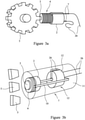
- cooling fins 40 may be mounted on the outside of the magnet 2 as shown in figure 7 .
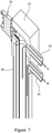
- a number of radially projecting cooling fins 40 are mounted on an annular element 41 which surrounds the magnet 2 and coil 4 which each have circular cross-sections.
- the cooling fins 40 and supporting annular element 41 are made of a good conductor of heat such as copper so as to help the conduction of heat from the magnet 2 and coil 4 to the cooling fins 40 and thence to the cooling fluid or gas which flows over the cooling fins and in the channel 42 formed between adjacent fins.
Landscapes
- Physics & Mathematics (AREA)
- General Physics & Mathematics (AREA)
- Electromagnetism (AREA)
- Chemical & Material Sciences (AREA)
- Engineering & Computer Science (AREA)
- Combustion & Propulsion (AREA)
- Investigating Or Analyzing Materials By The Use Of Magnetic Means (AREA)
- Transmission And Conversion Of Sensor Element Output (AREA)
- Measuring Volume Flow (AREA)
Description
- The invention relates to magnetic gas turbine sensors. In particular, embodiments of the invention relate to a cooled variable reluctance sensor for use in systems for determining the rotational speed of a gas turbine shaft, and may also be used in systems for determining if a shaft in the gas turbine engine has broken.
- Magnetic sensors such as eddy current sensors and/or variable reluctance (VR) sensors are often used as part of speed and/or torque monitoring systems on a gas turbine engine.
US4045738A ,EP2400307A ,EP3128332A ,EP1355131A andEP2073021A describe examples of VR sensors.GB2482468A - A magnetic gas turbine sensor is illustrated schematically in
Figure 2 . Thesensor 1 shown infigure 2 consists of apermanent magnet 2 attached to apole piece 3, and acoil 4 wound around thepole piece 3. Anoutput signal 8 is generated when the magnetic field strength within and around the pole piece changes. This is caused by the approach and passing offerrous metal teeth 5 on aphonic wheel 6 near the pole piece. The alternating presence and absence of ferrous metal teeth on the phonic wheel varies the reluctance, or "resistance of flow" of the magnetic field, which dynamically changes the magnetic field strength. This change in magnetic field strength induces a current into a coil winding which is attached to theoutput terminals 7. Theoutput signal 8 of a VR sensor is an AC voltage that varies in frequency that is directly proportional to the speed of the monitored target. - One complete waveform (cycle) occurs as each tooth of the wheel passes the sensing area (pole piece) of the sensor. The frequency of the signal, and so the speed of rotation, is determined from the zero crossing times of the signal. But typically the sensor "sinusoidal like" voltage output is required to cross zero volts and reach a minimum voltage either side of zero, for a reliable speed reading to be obtained. This minimum voltage requirement avoids electrical noise causing false readings.
- The same basic principle is equally applicable for the measurement of rotational speed via a direct monitoring of the passage of, for example turbine blades past an eddy current sensor (i.e. reluctance sensor) as described in
EP2073021 . The time between the passages of adjacent blades past a sensor can be measured to provide a signal from which rotational speed can be calculated. - Both the conventional type of variable reluctance sensor, where many turns of a conductive wire are wrapped around a magnetic pole piece, and the transformer type as described in
EP 1 355 131EP 0 169 670 , where, respectively, a few turns of a primary turn of conductive wire or an elongate strip with a slot defining a single turn are wrapped around magnetic pole piece, can be used.Figures 3a and 3b are schematic cross sections of two typical constructions of a variable reluctance sensor. - The sensor of
Figure 3a comprises amagnetic pole piece 3 around which an electricallyconductive wire 4 is wound. Apermanent magnet 2 is positioned adjacent a back face of the pole piece. The front face of the pole piece is, in use, located proximate to thephonic wheel 6 or wheels being sensed, as shown, for example, inFigure 1 . Thepole piece 3,conductive wire 4 andpermanent magnet 2 are all held in a housing (not shown infigure 3a ). An encapsulation material, typically a powder or an epoxy resin, is used to fill the space between the housing and the pole piece, magnet and conductive wire. The housing is fixed to another part of the turbine engine (not shown) and ensures that the front face of the pole piece is correctly positioned relative to the phonic wheel or wheels. The housing also provides protection from the harsh environment found inside gas turbine engines. - As each
tooth 5 of thephonic wheel 6 passes close to thefront face 9 of thepole piece 3 there is a change in the magnetic flux experienced by theconductive wire 4, due to the change in the reluctance of the magnetic circuit consisting of the pole piece, the phonic wheel and the air gap between the two. The changing magnetic flux results in a variable current induced in the conductive wire, from which the timing of the passage of the teeth on the phonic wheels past the pole piece can be determined. - The alternative sensor construction of
figure 3b is a transformer probe sensor of the type described inEP 0 169 670 andEP 1 3 55 131energisable pole piece 3, a closed loopelectrical circuit 10 having a first end which is wound around thepole piece 3 and forms apole piece coil 4 inductively coupled to the pole piece, the arrangement being such that movement of a body of magnetic material (e.g. the teeth of a phonic wheel) relative to the pole piece induces a current in the closed loop circuit, and a second end, remote from the pole piece, which forms a transformerprimary coil 11. A transformersecondary coil 12 is inductively coupled to theprimary coil 11, and terminated by a load resistance and means for measuring an output signal from the secondary coil. The primary and secondary coils form a transformer such that a current in the primary coil induces a voltage across the secondary coil. - Speed probes measure a gas turbine shaft speed. Very often a gas turbine has two or three shafts which are very difficult to access. The most difficult shaft to access is the inner shaft. This is the shaft connecting the fan with the low pressure turbine. Very often this shaft can only be accessed at the rear end of the turbine. However to reach the phonic wheel on the shaft the speed probe would have to pass through or be placed in the gas exhaust. The temperature of the exhaust gas is still very high, and could be about 700°C or more.
- Speed probes have two temperature sensitive components: a magnet and a pole piece. The operating temperature of these magnetic materials depends on their Curie temperature above which they lose their magnetic properties. There are magnets, such as ALNICO (family of iron alloys which in addition to iron are primarily composed of aluminium, cobalt and nickel and may also include copper and titanium) which have can operate up to 1000°C, but their strength is limited. It means that to obtain a sufficient magnetic flux at the air gap between the wheel and the pole piece they would have to be very large and bulky. Very often there is not enough space inside the probe to accommodate such large magnets and a different type of magnetic material must be used. However, such magnetically strong magnets as for example samarium cobalt have Curie temperatures or about 350°C. Therefore they can only be used at much lower temperatures and are not suitable for placing in the exhaust gas region of a jet engine.
- Another component which performance deteriorates with temperature is a coil. Insulation of coil wires, such as polyimide can operate up to 250 C. There are available ceramic coated wires, but they are not suitable for high vibration environments. Transformer probes of the sort described in
EP 0 169 670 can be used in higher temperature environments as they can use a strip of material which is less affected by temperature than the thin coils of magnetic material such as those used in conventional variable reluctance sensors. Ceramic coated coils have also been proposed for higher temperature environments. - The inventors of the subject application have appreciated that it is possible to provide a variable reluctance sensor able to better perform at higher temperatures without a significant increase in size of the sensor by providing a cooling mechanism for one or more of the sensor's magnetic elements and integrating that into the sensor.
-
JP H09 196530 claim 1 to which reference should now be made. The present invention is defined byclaim 1 to which reference should now also be made. -
US 2005/280412 discloses a blade detection sensor having an active cooling system;US 2015/198091 discloses an electric probe assembly for a gas turbine engine; andJP S59 175174 - Such an arrangement allows for more efficient cooling of the sensor pole piece and hence provides a sensor able to operate at higher temperatures.
- Cooling is made more efficient by cooling fluid being inside the sensor body and in direct or close contact with the magnet, pole piece and/or conductive sensing element requiring cooling.
- The provision of two cooling layers by the presence of the inner and outer fluid conduits means fluid flowing inside the probe or sensor through the inner conduit is protected from heat by the fluid flowing in the second fluid channel.
- The magnetic gas turbine sensor could be an eddy current sensor.
- The magnetic gas turbine sensor could be a variable reluctance sensor.
- The internal walls of the first sensor casing could define the first fluid conduit.
- Preferably the first sensor casing is configured such that fluid coolant flowing therethrough is in contact with the pole piece, magnet and/or conductive sensing element.
- Preferably the first sensor casing is configured such that fluid coolant flowing therethrough is in contact with the pole piece, magnet and conductive sensing element Preferably the first sensor casing is configured such that fluid coolant flowing therethrough is in direct contact with the pole piece, magnet and/or conductive sensing element.
- Preferably the sensor includes a mounting head portion for mounting the sensor to an engine casing or fixture and wherein the mounting head portion includes a fluid inlet connected to the fluid inlet of the first inner fluid conduit and a fluid outlet connected to the fluid outlet of the second outer fluid conduit each connected to respective ends of the fluid conduit. Preferably the second fluid conduit surrounds and is substantially concentric with the first fluid conduit.
- Preferably the magnet includes cooling fins arranged around its circumference and around through which coolant may flow.
- Preferably the sensor includes a non-magnetic heat sink block surrounding the magnet and/or pole piece.
- Preferably the non-magnetic heat sink block includes cooling fins.
- The sensor may include a source of liquid coolant connected to the fluid conduit or conduits.
- The sensor may include a pump for pumping liquid coolant through the fluid conduit or conduits.
- The sensor may include means for pressurising coolant in the fluid conduit or conduits.
- Embodiments of the invention will be further described, by way of example only, with reference to the accompanying drawings in which:
-
Figure 1 is a schematic cross-section through a jet engine or gas turbine showing possible locations of magnetic speed and/or torque sensing probes; -
Figure 2 is a schematic illustration of a magnetic variable reluctance (VR) sensing probe; -
Figure 3a illustrates a variable reluctance probe positioned adjacent to a phonic wheel; -
Figure 3b illustrates an alternative variable reluctance transformer probe positioned adjacent to a phonic wheel; -
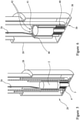
Figure 4 is a schematic illustration of a first embodiment of the invention; -
Figure 5 is an illustration of the bottom (sensing end) of the probe offigure 4 ; -
Figure 6 is an illustration of an alternative magnet construction for use in embodiments of the invention; and -
Figure 7 illustrates the top (mounting end) of the probe offigure 4 . -
Figure 1 shows a typical two spool turbofan jet engine 13 having anintake 14,fan 15,high pressure compressor 17a,low pressure compressor 17b,combustion chamber 18,fan nozzle 19,high pressure turbine 20 a, andlow pressure turbine 20b andcone 21. The construction of such jet engines is well known so will not be described in detail. - The
engine 13 includes afan 15 across theair intake 14. Thefan 15 is mounted on aninner shaft 22 on which are also mounted the low pressure turbine rotors or blades 20 as well as the low pressure compressor rotors or blades. The high pressure turbine and compressor rotors or blades are mounted on an outerhigh pressure shaft 23. - In order to measure the speed of the inner or low pressure shaft 22 a phonic wheel (not shown) may be placed on the low pressure shaft behind the
cone 21 or as the last thing inside thecone 21. An innershaft speed sensor 24a is mounted on the engine casing with the sensing end adjacent that inner shaft phonic wheel. - In order to sense the speed of the
outer shaft 23 supporting the high pressure turbine and compressor, a phonic wheel (not shown) may be placed on theouter shaft 23 between the locations of the high and low pressure turbine rotors or blades. An outershaft speed sensor 24b is mounted on the engine casing with the sensing end adjacent that outer shaft phonic wheel. - The
cone 21 is in the exhaust from the engine or turbine and therefore is, when the jet engine is in use, a high temperature environment. Temperatures in the engine can exceed 800 °C which means that the environment in which the innershaft speed sensor 24a should be located is an aggressive one. Furthermore and as can be seen fromfigure 1 , space is limited in the engine for the speed sensor. - There are two types of speed sensors which may require different cooling systems. One type is that described above in connection with, and shown in,
figure 3a and using standard multi turn coils. The second type is that described above in connection with, and shown in,figure 3b and using a transformer probe and a primary turn. - Referring to
figures 4 to 7 , asensor probe 25 comprises amagnet 2,pole piece 3,coil 4 wound around thepole piece 3 and including leads 26 connecting the respective ends of thecoil 4 to sensing circuitry (not shown) coupled to a mountinghead 27. Theprobe 25 is held within a probe body orhousing 28 which may be made of a nickel alloy such as Inconel 600. Inconel is a registered trade mark of Huntington Alloy Corporation. Inconel 600 is a nickel-chromium alloy with oxidation resistance at high temperatures and is used for, inter alia, furnace components. More information on Inconel 600 can be found at http://www.hightempmetals.com/techdata/hitemplnconel600data.php . The mountinghead 27 may also be of Inconel 600 (or similar) or of a ceramic material as described inEP 2 023 106 - The sensor housing or
body 28 has a firstdistal end 29 with asensing face 30 through which thepole piece 3 projects and which forms the sensing end of the probe. Theproximal end 31 of the sensor housing includes the mountinghead 27 which can be mounted to the engine casing and which has aconnector element 32 for connecting the sensor leads 26 to sensing circuitry. Details of the connections to the sensing circuitry may be as described inEP 2 023 106 - The mounting head includes a gas or
fluid inlet 33 and a gas orfluid outlet 34 which are connected to a fluid conduit or 35 which extends from theinlet 33 in the mountinghead 27 to, and around, themagnet 2 andsensing coil 4 and then back to thefluid outlet 34. Arrows A and B show the direction of fluid flow from theinlet 33 to theoutlet 34. The inflow A is cooler than the outflow B: coolant fluid such as air is heated up by and transports heat away from themagnet 2,pole piece 3,coil 4 and probehousing 28 as it flows through theprobe 25. - The first portion of the fluid or cooling passage running from the
fluid inlet 33 to themagnet 2 is a central orinner inflow conduit 36 running down the middle of thesensor housing 28. The magnet, pole piece and coil making up the sensing element are located within theinner conduit 36. Concentric with the inner inflow conduit is a concentric outflowouter conduit 37 disposed around the inner inflow conduit and connected thereto by aspace 38 at the bottom or distal end of theprobe 25 between the bottom of the wall of the central inflow passage and the end or bottom surface of the probe or sensor housing (i.e. at the sensing end of the probe). Alternatively channel/holes may be provided in the walls of the distal or bottom end of the centralinner conduit 36. Theoutflow conduit 37 includes a firstdistal section 39 adjacent the sensing element which is broader than the second proximal elements connecting the distal section to the fluid outlet in the mounting head. The walls of the fluid passages may (like the rest of the housing) be made from Inconel 600. - In the embodiment shown in
figures 4 to 6 , themagnet 2 may be a rare earth magnet such as a samarium cobalt magnet; thepole piece 3 may be made of a soft magnetic material such as iron or magnetic stainless steel; thecoil 4 may be made from copper wire with polyamide insulation; whilst the walls of thefluid passages head 27 andsensor housing 28 may all be made of Inconel 600 or something similar capable of withstanding the high temperatures in which the sensor or probe 25 will be placed and operate. - A cooling fluid may be provided to the
probe housing 25 through thespecial fluid inlet 33 and flows in the central part of theprobe 25 which defines aninflow passage 36 to themagnet 2,pole piece 3 andcoil 4. The fluid then returns in the outside cavity of the probe which defines theoutflow passage 37. Since the heat source (hot exhaust gas for probe placed in exhaust of turbine) would be normally located outside, at half length of the probe, the cooling fluid, after absorbing this heat travels upwards directly to the exhaust. The flow is determined empirically for various engine-speed probe configurations. The cooling fluid could be air taken from the engine bypass, or air or another gas from a special compressor. However liquid coolant will have a higher specific heat components meaning a smaller volume of coolant would be suitable. In view of the size constraints of a magnetic sensor nonconductive liquid coolants may be preferred. A suitable cooling fluid would be a nonconductive fluid such as a dielectric fluid such as that available from 3M under the trade mark FLOURINET. Fluorinert is the trademarked brand name for the line of electronics coolants liquids sold commercially by 3M. It is an electrically insulating, stable fluorocarbon-based fluid, which is used in various cooling applications. It is mainly used for cooling electronics. Different molecular formulations are available with a variety of boiling points, allowing it to be used in "single-phase" applications, where it remains a liquid, or for "two-phase" applications, where the liquid boils to remove additional heat by evaporative cooling. An example of one of the compounds 3M uses is FC-72 (perfluorohexane, C6F14). Perfluorohexane is used for low-temperature heat-transfer applications due to its 56 °C (133 °F) boiling point. Another example is FC-75, perfluoro (2-butyl-tetrahydrofurane). There are 3M fluids that can handle up to 215 °C (419 °F), such as FC-70 (perfluorotripentylamine). - Other suitable coolants include distilled water, Novec 1230 (a fluorinated ketone manufactured by 3M), Fluid XP+ (a series of coolants manufactured by Fluid XP+), or oil. The liquid coolant could be pressurised so as to operate at higher temperatures.
- To enhance cooling of the magnet
special cooling fins 40 may be mounted on the outside of themagnet 2 as shown infigure 7 . A number of radially projectingcooling fins 40 are mounted on anannular element 41 which surrounds themagnet 2 andcoil 4 which each have circular cross-sections. The coolingfins 40 and supportingannular element 41 are made of a good conductor of heat such as copper so as to help the conduction of heat from themagnet 2 andcoil 4 to the coolingfins 40 and thence to the cooling fluid or gas which flows over the cooling fins and in thechannel 42 formed between adjacent fins.
Claims (10)
- A magnetic gas turbine sensor (25) for sensing the speed and/or torque of a shaft in a gas turbine engine, the sensor comprising:a magnetic pole piece (3);a magnet (2) associated with the pole piece (3);a conductive sensing element (4) wrapped or wound around the pole piece and inductively coupled to the pole piece; anda first sensor casing surrounding and housing the pole piece, magnet and conductive sensing element; the first sensor casing (35) defining a first inner fluid conduit (36) for fluid coolant, the first fluid conduit being arranged to allow a fluid flow within the first sensor casing (35) and running alongside and/or adjacent the pole piece, magnet and/or conductive sensing element,and wherein the sensor includes a first distal sensing end (29) adjacent the pole piece for location adjacent the path of the shaft or an element rotating with the shaft, and a second proximal mounting end (31) for mounting to a surface on or adjacent the enginecharacterised bythe sensor also including a second outer sensor casing (28) surrounding the first sensor casing and defining a second outer fluid conduit (37) for fluid coolant, the outer fluid conduit (37) being defined by the space between the first sensor casing (35) and the second sensor casing (28) and at least partially surrounding the first fluid conduit,and whereinthe first fluid conduit (36) has a fluid inlet towards the proximal mounting end of the sensor, the second fluid conduit (37) has a fluid outlet towards the proximal mounting end of the sensor, and the first and second fluid conduits are in communication with each other in the sensor only in a region at the distal sensing end of the sensor and being arranged such that fluid coolant may flow into the sensor at its proximal mounting end, through the first fluid conduit over or through the pole piece, magnet and/or conductive sensing element to the sensing end, andthen through the second fluid conduit from the distal sensing end to the outlet at the proximal mounting end.
- A magnetic gas turbine sensor according to claim 1 wherein internal walls of the first sensor casing define the first fluid conduit (35).
- A magnetic gas turbine sensor according to claim 1 wherein the first sensor casing is configured such that fluid coolant flowing therethrough is in contact with the pole piece, magnet and/or conductive sensing element.
- A sensor according to any preceding claim wherein the sensor includes a mounting head portion (27) for mounting the sensor to an engine casing or fixture and wherein the mounting head portion includes a mounting head fluid inlet (33) connected to the fluid inlet of the first fluid channel and a mounting head fluid outlet (34) connected to the fluid outlet of the second fluid channel.
- A sensor according to claim 1 wherein the second outer fluid conduit surrounds and is substantially concentric with the first inner fluid conduit
- A sensor according to any preceding claim wherein the magnet (2) includes cooling fins (40) arranged around its circumference and over which coolant may flow.
- A sensor according to any preceding claim wherein the sensor includes a non-magnetic heat sink block (46) surrounding the magnet and/or pole piece.
- A sensor according to claim 7 wherein the non-magnetic heat sink block includes cooling fins.
- A sensor according to any preceding claim including a source of liquid coolant connected to the fluid conduit or conduits.
- A sensor according to claim 9 including a pump for pumping the liquid coolant through the fluid conduit or conduits.
Applications Claiming Priority (1)
| Application Number | Priority Date | Filing Date | Title |
|---|---|---|---|
| GB1800330.1A GB2576471A (en) | 2018-01-09 | 2018-01-09 | Magnetic gas turbine sensor |
Publications (3)
| Publication Number | Publication Date |
|---|---|
| EP3517977A2 EP3517977A2 (en) | 2019-07-31 |
| EP3517977A3 EP3517977A3 (en) | 2019-10-30 |
| EP3517977B1 true EP3517977B1 (en) | 2022-03-02 |
Family
ID=61190485
Family Applications (1)
| Application Number | Title | Priority Date | Filing Date |
|---|---|---|---|
| EP19150844.9A Active EP3517977B1 (en) | 2018-01-09 | 2019-01-08 | Magnetic gas turbine sensor |
Country Status (4)
| Country | Link |
|---|---|
| US (1) | US10976221B2 (en) |
| EP (1) | EP3517977B1 (en) |
| CA (1) | CA3029373A1 (en) |
| GB (1) | GB2576471A (en) |
Families Citing this family (1)
| Publication number | Priority date | Publication date | Assignee | Title |
|---|---|---|---|---|
| US11939920B1 (en) * | 2023-02-06 | 2024-03-26 | Rolls-Royce Corporation | Ultra high temperature speed sensor system in a gas turbine engine |
Family Cites Families (27)
| Publication number | Priority date | Publication date | Assignee | Title |
|---|---|---|---|---|
| GB832242A (en) * | 1956-11-30 | 1960-04-06 | Power Jets Res & Dev Ltd | Improvements in or relating to dimension indicating devices |
| CH368541A (en) * | 1959-02-02 | 1963-04-15 | Schlatter Ag | transformer |
| CA984463A (en) | 1972-04-20 | 1976-02-24 | Simmonds Precision Products | Eddy current sensor |
| US3984713A (en) | 1975-04-04 | 1976-10-05 | The Bendix Corporation | Magnetic speed sensor with compensating pole |
| US4045738A (en) | 1976-03-08 | 1977-08-30 | General Electric Company | Variable reluctance speed sensor of integral construction utilizing a shielded high coercive force rare earth magnet positioned directly adjacent the sensing rotating element |
| JPS59175174U (en) * | 1983-05-11 | 1984-11-22 | 株式会社日立製作所 | High temperature speed detector |
| GB8416109D0 (en) | 1984-06-23 | 1984-07-25 | Schlumberger Electronics Uk | Proximity sensor |
| US4901015A (en) | 1988-09-21 | 1990-02-13 | Sundstrand Corporation | Ambient electromagnetic field compensating magnetic pick-up circuit for integrated drive generators |
| US5166626A (en) * | 1990-05-29 | 1992-11-24 | General Electric Company | Electrical capacitance clearanceometer |
| JPH05180857A (en) * | 1991-12-20 | 1993-07-23 | Ishikawajima Harima Heavy Ind Co Ltd | Non-contact tachometer or displacement gauge mounting structure |
| GB2265221B (en) | 1992-03-21 | 1995-04-26 | Schlumberger Ind Ltd | Inductive sensors |
| US5446269A (en) * | 1993-05-27 | 1995-08-29 | Inductotherm Corp. | Tubing shape, particularly for fabricating an induction coil |
| JP3374549B2 (en) * | 1994-09-30 | 2003-02-04 | 神鋼電機株式会社 | Cold wall melting furnace and melting method capable of melting under ultra-high vacuum |
| JPH09196530A (en) * | 1996-01-18 | 1997-07-31 | Mitsubishi Heavy Ind Ltd | Cooling device for rotation signal detector |
| US7170284B2 (en) * | 2002-02-13 | 2007-01-30 | Hood Technology Corporation | Blade detection sensor having an active cooling system |
| GB2387656B (en) | 2002-04-16 | 2004-03-03 | Weston Aerospace | Transformer probe |
| TWI230899B (en) | 2003-03-10 | 2005-04-11 | Sunplus Technology Co Ltd | Processor and method using parity check to proceed command mode switch |
| GB2451693B (en) | 2007-08-09 | 2011-12-14 | Weston Aerospace Ltd | Thermocouple Head Unit |
| GB2455801B (en) | 2007-12-21 | 2010-04-28 | Weston Aerospace Ltd | Method and apparatus for monitoring the rotational speed of a shaft |
| GB2482468B (en) | 2010-05-18 | 2013-12-18 | Weston Aerospace Ltd | Method and system for inductive sensing of blades in a turbine engine |
| GB2481414B (en) * | 2010-06-22 | 2012-09-19 | Weston Aerospace Ltd | Speed or torque probe for gas turbine engines |
| GB201010862D0 (en) * | 2010-06-29 | 2010-08-11 | Rolls Royce Plc | High temperature measurement probe |
| GB2515483A (en) * | 2013-06-24 | 2014-12-31 | Weston Aerospace | Cooled Thermocouple |
| US9551281B2 (en) * | 2014-01-15 | 2017-01-24 | Pratt & Whitney Canada Corp. | Electric probe assembly, gas turbine engine having same and method of cooling same |
| GB2522210B (en) * | 2014-01-16 | 2018-10-10 | Weston Aerospace Ltd | Engine probe |
| GB2540379A (en) | 2015-07-14 | 2017-01-18 | Weston Aerospace Ltd | Magnetic sensing system and method for detecting shaft speed |
| GB2540770A (en) | 2015-07-27 | 2017-02-01 | Weston Aerospace Ltd | Cooled thermocouple |
-
2018
- 2018-01-09 GB GB1800330.1A patent/GB2576471A/en not_active Withdrawn
-
2019
- 2019-01-08 US US16/242,484 patent/US10976221B2/en active Active
- 2019-01-08 EP EP19150844.9A patent/EP3517977B1/en active Active
- 2019-01-09 CA CA3029373A patent/CA3029373A1/en active Pending
Also Published As
| Publication number | Publication date |
|---|---|
| GB2576471A (en) | 2020-02-26 |
| EP3517977A3 (en) | 2019-10-30 |
| US20190212229A1 (en) | 2019-07-11 |
| CA3029373A1 (en) | 2019-07-09 |
| GB201800330D0 (en) | 2018-02-21 |
| EP3517977A2 (en) | 2019-07-31 |
| US10976221B2 (en) | 2021-04-13 |
Similar Documents
| Publication | Publication Date | Title |
|---|---|---|
| KR101951382B1 (en) | Impeller flow meter | |
| KR101928810B1 (en) | Temperature and angular speed sensing apparatus | |
| US20100213929A1 (en) | Rotor blade sensor | |
| WO2008057799A2 (en) | Split rogowski coil current measuring device and methods | |
| CN104136889A (en) | Sensor device for contactless detection of rotational properties of rotatable objects | |
| RU2659463C2 (en) | Magnetic flowmeter with polytetrafluoroethylene electrodes | |
| US4324144A (en) | Turbine flowmeter | |
| US6927567B1 (en) | Passive eddy current blade detection sensor | |
| CA1255772A (en) | Proximity sensor | |
| US10976221B2 (en) | Magnetic gas turbine sensor | |
| EP2601485A1 (en) | Electromagnetic flow meter | |
| US8018225B2 (en) | System and method for sensing the periodic position of an object | |
| CA2593553C (en) | Aerospace movement probe | |
| CN113640538A (en) | Magnetoelectric Speed Sensor and Speed Detection System | |
| CA2735220A1 (en) | System and method for sensing the periodic position of an object | |
| EP2131201B1 (en) | High temperature speed sensor | |
| RU2001128250A (en) | The method of measuring the motion parameters of the ends of the blades of the rotor of a turbomachine and a device for its implementation | |
| WO2013093399A1 (en) | Proximity sensor with conductive protective shield comprising discontinuities such as slits | |
| SU1305318A1 (en) | Downhole magnetic locator | |
| JP2018115949A (en) | Fluid machinery | |
| Haase et al. | Advances in through-the-case eddy current sensors | |
| EP0802414A2 (en) | Shaft seal and shaft sensor | |
| CN111551220A (en) | Full bore magnetic flowmeter assembly with temperature sensing element | |
| RU2778429C1 (en) | Liquid metal electromagnetic flow meter | |
| RU2258228C1 (en) | Yalovegy frequency tachometer |
Legal Events
| Date | Code | Title | Description |
|---|---|---|---|
| PUAI | Public reference made under article 153(3) epc to a published international application that has entered the european phase |
Free format text: ORIGINAL CODE: 0009012 |
|
| STAA | Information on the status of an ep patent application or granted ep patent |
Free format text: STATUS: THE APPLICATION HAS BEEN PUBLISHED |
|
| AK | Designated contracting states |
Kind code of ref document: A2 Designated state(s): AL AT BE BG CH CY CZ DE DK EE ES FI FR GB GR HR HU IE IS IT LI LT LU LV MC MK MT NL NO PL PT RO RS SE SI SK SM TR |
|
| AX | Request for extension of the european patent |
Extension state: BA ME |
|
| PUAL | Search report despatched |
Free format text: ORIGINAL CODE: 0009013 |
|
| AK | Designated contracting states |
Kind code of ref document: A3 Designated state(s): AL AT BE BG CH CY CZ DE DK EE ES FI FR GB GR HR HU IE IS IT LI LT LU LV MC MK MT NL NO PL PT RO RS SE SI SK SM TR |
|
| AX | Request for extension of the european patent |
Extension state: BA ME |
|
| RIC1 | Information provided on ipc code assigned before grant |
Ipc: G01L 3/10 20060101ALI20190920BHEP Ipc: G01P 3/488 20060101AFI20190920BHEP Ipc: G01P 3/49 20060101ALI20190920BHEP |
|
| STAA | Information on the status of an ep patent application or granted ep patent |
Free format text: STATUS: REQUEST FOR EXAMINATION WAS MADE |
|
| 17P | Request for examination filed |
Effective date: 20200430 |
|
| RBV | Designated contracting states (corrected) |
Designated state(s): AL AT BE BG CH CY CZ DE DK EE ES FI FR GB GR HR HU IE IS IT LI LT LU LV MC MK MT NL NO PL PT RO RS SE SI SK SM TR |
|
| RIC1 | Information provided on ipc code assigned before grant |
Ipc: G01P 3/488 20060101AFI20210715BHEP Ipc: G01P 3/49 20060101ALI20210715BHEP Ipc: G01L 3/14 20060101ALI20210715BHEP |
|
| GRAP | Despatch of communication of intention to grant a patent |
Free format text: ORIGINAL CODE: EPIDOSNIGR1 |
|
| STAA | Information on the status of an ep patent application or granted ep patent |
Free format text: STATUS: GRANT OF PATENT IS INTENDED |
|
| INTG | Intention to grant announced |
Effective date: 20210908 |
|
| GRAS | Grant fee paid |
Free format text: ORIGINAL CODE: EPIDOSNIGR3 |
|
| GRAA | (expected) grant |
Free format text: ORIGINAL CODE: 0009210 |
|
| STAA | Information on the status of an ep patent application or granted ep patent |
Free format text: STATUS: THE PATENT HAS BEEN GRANTED |
|
| AK | Designated contracting states |
Kind code of ref document: B1 Designated state(s): AL AT BE BG CH CY CZ DE DK EE ES FI FR GB GR HR HU IE IS IT LI LT LU LV MC MK MT NL NO PL PT RO RS SE SI SK SM TR |
|
| REG | Reference to a national code |
Ref country code: GB Ref legal event code: FG4D |
|
| REG | Reference to a national code |
Ref country code: CH Ref legal event code: EP Ref country code: AT Ref legal event code: REF Ref document number: 1472680 Country of ref document: AT Kind code of ref document: T Effective date: 20220315 |
|
| REG | Reference to a national code |
Ref country code: DE Ref legal event code: R096 Ref document number: 602019011979 Country of ref document: DE |
|
| REG | Reference to a national code |
Ref country code: IE Ref legal event code: FG4D |
|
| REG | Reference to a national code |
Ref country code: LT Ref legal event code: MG9D |
|
| REG | Reference to a national code |
Ref country code: NL Ref legal event code: MP Effective date: 20220302 |
|
| PG25 | Lapsed in a contracting state [announced via postgrant information from national office to epo] |
Ref country code: SE Free format text: LAPSE BECAUSE OF FAILURE TO SUBMIT A TRANSLATION OF THE DESCRIPTION OR TO PAY THE FEE WITHIN THE PRESCRIBED TIME-LIMIT Effective date: 20220302 Ref country code: RS Free format text: LAPSE BECAUSE OF FAILURE TO SUBMIT A TRANSLATION OF THE DESCRIPTION OR TO PAY THE FEE WITHIN THE PRESCRIBED TIME-LIMIT Effective date: 20220302 Ref country code: NO Free format text: LAPSE BECAUSE OF FAILURE TO SUBMIT A TRANSLATION OF THE DESCRIPTION OR TO PAY THE FEE WITHIN THE PRESCRIBED TIME-LIMIT Effective date: 20220602 Ref country code: LT Free format text: LAPSE BECAUSE OF FAILURE TO SUBMIT A TRANSLATION OF THE DESCRIPTION OR TO PAY THE FEE WITHIN THE PRESCRIBED TIME-LIMIT Effective date: 20220302 Ref country code: HR Free format text: LAPSE BECAUSE OF FAILURE TO SUBMIT A TRANSLATION OF THE DESCRIPTION OR TO PAY THE FEE WITHIN THE PRESCRIBED TIME-LIMIT Effective date: 20220302 Ref country code: ES Free format text: LAPSE BECAUSE OF FAILURE TO SUBMIT A TRANSLATION OF THE DESCRIPTION OR TO PAY THE FEE WITHIN THE PRESCRIBED TIME-LIMIT Effective date: 20220302 Ref country code: BG Free format text: LAPSE BECAUSE OF FAILURE TO SUBMIT A TRANSLATION OF THE DESCRIPTION OR TO PAY THE FEE WITHIN THE PRESCRIBED TIME-LIMIT Effective date: 20220602 |
|
| REG | Reference to a national code |
Ref country code: AT Ref legal event code: MK05 Ref document number: 1472680 Country of ref document: AT Kind code of ref document: T Effective date: 20220302 |
|
| PG25 | Lapsed in a contracting state [announced via postgrant information from national office to epo] |
Ref country code: PL Free format text: LAPSE BECAUSE OF FAILURE TO SUBMIT A TRANSLATION OF THE DESCRIPTION OR TO PAY THE FEE WITHIN THE PRESCRIBED TIME-LIMIT Effective date: 20220302 Ref country code: LV Free format text: LAPSE BECAUSE OF FAILURE TO SUBMIT A TRANSLATION OF THE DESCRIPTION OR TO PAY THE FEE WITHIN THE PRESCRIBED TIME-LIMIT Effective date: 20220302 Ref country code: GR Free format text: LAPSE BECAUSE OF FAILURE TO SUBMIT A TRANSLATION OF THE DESCRIPTION OR TO PAY THE FEE WITHIN THE PRESCRIBED TIME-LIMIT Effective date: 20220603 Ref country code: FI Free format text: LAPSE BECAUSE OF FAILURE TO SUBMIT A TRANSLATION OF THE DESCRIPTION OR TO PAY THE FEE WITHIN THE PRESCRIBED TIME-LIMIT Effective date: 20220302 |
|
| PG25 | Lapsed in a contracting state [announced via postgrant information from national office to epo] |
Ref country code: NL Free format text: LAPSE BECAUSE OF FAILURE TO SUBMIT A TRANSLATION OF THE DESCRIPTION OR TO PAY THE FEE WITHIN THE PRESCRIBED TIME-LIMIT Effective date: 20220302 |
|
| PG25 | Lapsed in a contracting state [announced via postgrant information from national office to epo] |
Ref country code: SM Free format text: LAPSE BECAUSE OF FAILURE TO SUBMIT A TRANSLATION OF THE DESCRIPTION OR TO PAY THE FEE WITHIN THE PRESCRIBED TIME-LIMIT Effective date: 20220302 Ref country code: SK Free format text: LAPSE BECAUSE OF FAILURE TO SUBMIT A TRANSLATION OF THE DESCRIPTION OR TO PAY THE FEE WITHIN THE PRESCRIBED TIME-LIMIT Effective date: 20220302 Ref country code: RO Free format text: LAPSE BECAUSE OF FAILURE TO SUBMIT A TRANSLATION OF THE DESCRIPTION OR TO PAY THE FEE WITHIN THE PRESCRIBED TIME-LIMIT Effective date: 20220302 Ref country code: PT Free format text: LAPSE BECAUSE OF FAILURE TO SUBMIT A TRANSLATION OF THE DESCRIPTION OR TO PAY THE FEE WITHIN THE PRESCRIBED TIME-LIMIT Effective date: 20220704 Ref country code: EE Free format text: LAPSE BECAUSE OF FAILURE TO SUBMIT A TRANSLATION OF THE DESCRIPTION OR TO PAY THE FEE WITHIN THE PRESCRIBED TIME-LIMIT Effective date: 20220302 Ref country code: CZ Free format text: LAPSE BECAUSE OF FAILURE TO SUBMIT A TRANSLATION OF THE DESCRIPTION OR TO PAY THE FEE WITHIN THE PRESCRIBED TIME-LIMIT Effective date: 20220302 Ref country code: AT Free format text: LAPSE BECAUSE OF FAILURE TO SUBMIT A TRANSLATION OF THE DESCRIPTION OR TO PAY THE FEE WITHIN THE PRESCRIBED TIME-LIMIT Effective date: 20220302 |
|
| PG25 | Lapsed in a contracting state [announced via postgrant information from national office to epo] |
Ref country code: IS Free format text: LAPSE BECAUSE OF FAILURE TO SUBMIT A TRANSLATION OF THE DESCRIPTION OR TO PAY THE FEE WITHIN THE PRESCRIBED TIME-LIMIT Effective date: 20220702 Ref country code: AL Free format text: LAPSE BECAUSE OF FAILURE TO SUBMIT A TRANSLATION OF THE DESCRIPTION OR TO PAY THE FEE WITHIN THE PRESCRIBED TIME-LIMIT Effective date: 20220302 |
|
| REG | Reference to a national code |
Ref country code: DE Ref legal event code: R097 Ref document number: 602019011979 Country of ref document: DE |
|
| PLBE | No opposition filed within time limit |
Free format text: ORIGINAL CODE: 0009261 |
|
| STAA | Information on the status of an ep patent application or granted ep patent |
Free format text: STATUS: NO OPPOSITION FILED WITHIN TIME LIMIT |
|
| PG25 | Lapsed in a contracting state [announced via postgrant information from national office to epo] |
Ref country code: DK Free format text: LAPSE BECAUSE OF FAILURE TO SUBMIT A TRANSLATION OF THE DESCRIPTION OR TO PAY THE FEE WITHIN THE PRESCRIBED TIME-LIMIT Effective date: 20220302 |
|
| 26N | No opposition filed |
Effective date: 20221205 |
|
| PG25 | Lapsed in a contracting state [announced via postgrant information from national office to epo] |
Ref country code: SI Free format text: LAPSE BECAUSE OF FAILURE TO SUBMIT A TRANSLATION OF THE DESCRIPTION OR TO PAY THE FEE WITHIN THE PRESCRIBED TIME-LIMIT Effective date: 20220302 |
|
| P01 | Opt-out of the competence of the unified patent court (upc) registered |
Effective date: 20230530 |
|
| REG | Reference to a national code |
Ref country code: CH Ref legal event code: PL |
|
| PG25 | Lapsed in a contracting state [announced via postgrant information from national office to epo] |
Ref country code: LU Free format text: LAPSE BECAUSE OF NON-PAYMENT OF DUE FEES Effective date: 20230108 |
|
| REG | Reference to a national code |
Ref country code: BE Ref legal event code: MM Effective date: 20230131 |
|
| PG25 | Lapsed in a contracting state [announced via postgrant information from national office to epo] |
Ref country code: LI Free format text: LAPSE BECAUSE OF NON-PAYMENT OF DUE FEES Effective date: 20230131 Ref country code: CH Free format text: LAPSE BECAUSE OF NON-PAYMENT OF DUE FEES Effective date: 20230131 |
|
| PG25 | Lapsed in a contracting state [announced via postgrant information from national office to epo] |
Ref country code: BE Free format text: LAPSE BECAUSE OF NON-PAYMENT OF DUE FEES Effective date: 20230131 |
|
| PGFP | Annual fee paid to national office [announced via postgrant information from national office to epo] |
Ref country code: GB Payment date: 20231227 Year of fee payment: 6 |
|
| PG25 | Lapsed in a contracting state [announced via postgrant information from national office to epo] |
Ref country code: IE Free format text: LAPSE BECAUSE OF NON-PAYMENT OF DUE FEES Effective date: 20230108 |
|
| PGFP | Annual fee paid to national office [announced via postgrant information from national office to epo] |
Ref country code: DE Payment date: 20240110 Year of fee payment: 6 |
|
| PGFP | Annual fee paid to national office [announced via postgrant information from national office to epo] |
Ref country code: IT Payment date: 20240105 Year of fee payment: 6 Ref country code: FR Payment date: 20240115 Year of fee payment: 6 |
|
| PG25 | Lapsed in a contracting state [announced via postgrant information from national office to epo] |
Ref country code: MC Free format text: LAPSE BECAUSE OF FAILURE TO SUBMIT A TRANSLATION OF THE DESCRIPTION OR TO PAY THE FEE WITHIN THE PRESCRIBED TIME-LIMIT Effective date: 20220302 |
|
| PG25 | Lapsed in a contracting state [announced via postgrant information from national office to epo] |
Ref country code: MC Free format text: LAPSE BECAUSE OF FAILURE TO SUBMIT A TRANSLATION OF THE DESCRIPTION OR TO PAY THE FEE WITHIN THE PRESCRIBED TIME-LIMIT Effective date: 20220302 |
|
| PG25 | Lapsed in a contracting state [announced via postgrant information from national office to epo] |
Ref country code: CY Free format text: LAPSE BECAUSE OF FAILURE TO SUBMIT A TRANSLATION OF THE DESCRIPTION OR TO PAY THE FEE WITHIN THE PRESCRIBED TIME-LIMIT; INVALID AB INITIO Effective date: 20190108 |
|
| REG | Reference to a national code |
Ref country code: DE Ref legal event code: R119 Ref document number: 602019011979 Country of ref document: DE |
|
| PG25 | Lapsed in a contracting state [announced via postgrant information from national office to epo] |
Ref country code: HU Free format text: LAPSE BECAUSE OF FAILURE TO SUBMIT A TRANSLATION OF THE DESCRIPTION OR TO PAY THE FEE WITHIN THE PRESCRIBED TIME-LIMIT; INVALID AB INITIO Effective date: 20190108 |
|
| GBPC | Gb: european patent ceased through non-payment of renewal fee |
Effective date: 20250108 |
|
| PG25 | Lapsed in a contracting state [announced via postgrant information from national office to epo] |
Ref country code: DE Free format text: LAPSE BECAUSE OF NON-PAYMENT OF DUE FEES Effective date: 20250801 |
|
| PG25 | Lapsed in a contracting state [announced via postgrant information from national office to epo] |
Ref country code: GB Free format text: LAPSE BECAUSE OF NON-PAYMENT OF DUE FEES Effective date: 20250108 |
|
| PG25 | Lapsed in a contracting state [announced via postgrant information from national office to epo] |
Ref country code: FR Free format text: LAPSE BECAUSE OF NON-PAYMENT OF DUE FEES Effective date: 20250131 |
|
| PG25 | Lapsed in a contracting state [announced via postgrant information from national office to epo] |
Ref country code: TR Free format text: LAPSE BECAUSE OF FAILURE TO SUBMIT A TRANSLATION OF THE DESCRIPTION OR TO PAY THE FEE WITHIN THE PRESCRIBED TIME-LIMIT Effective date: 20220302 |
|
| PG25 | Lapsed in a contracting state [announced via postgrant information from national office to epo] |
Ref country code: IT Free format text: LAPSE BECAUSE OF NON-PAYMENT OF DUE FEES Effective date: 20250108 |