US4045738A - Variable reluctance speed sensor of integral construction utilizing a shielded high coercive force rare earth magnet positioned directly adjacent the sensing rotating element - Google Patents

Variable reluctance speed sensor of integral construction utilizing a shielded high coercive force rare earth magnet positioned directly adjacent the sensing rotating element Download PDF

Info

Publication number
US4045738A
US4045738A US05/665,047 US66504776A US4045738A US 4045738 A US4045738 A US 4045738A US 66504776 A US66504776 A US 66504776A US 4045738 A US4045738 A US 4045738A
Authority
US
United States
Prior art keywords
magnet
flux
core
variable reluctance
wall means
Prior art date
Legal status (The legal status is an assumption and is not a legal conclusion. Google has not performed a legal analysis and makes no representation as to the accuracy of the status listed.)
Expired - Lifetime
Application number
US05/665,047
Inventor
Colby E. Buzzell
Current Assignee (The listed assignees may be inaccurate. Google has not performed a legal analysis and makes no representation or warranty as to the accuracy of the list.)
Amespace Inc
Ametek Aerospace Products Inc
Original Assignee
General Electric Co
Priority date (The priority date is an assumption and is not a legal conclusion. Google has not performed a legal analysis and makes no representation as to the accuracy of the date listed.)
Filing date
Publication date
Application filed by General Electric Co filed Critical General Electric Co
Priority to US05/665,047 priority Critical patent/US4045738A/en
Priority to FR7706089A priority patent/FR2344022A1/en
Priority to GB9808/77A priority patent/GB1516078A/en
Application granted granted Critical
Publication of US4045738A publication Critical patent/US4045738A/en
Assigned to TECHNOLOGY, INC. 64 A DE CORPORATION reassignment TECHNOLOGY, INC. 64 A DE CORPORATION ASSIGNMENT OF ASSIGNORS INTEREST. Assignors: GENERAL ELECTRIC COMPANY, A NY CORPORATION
Assigned to AMESPACE, INC. A DE CORPORATION reassignment AMESPACE, INC. A DE CORPORATION ASSIGNMENT OF ASSIGNORS INTEREST. Assignors: TECHNOLOGY, INC., A CORPORATION OF DE
Assigned to CHASE MANHATTAN BANK, N.A., THE reassignment CHASE MANHATTAN BANK, N.A., THE SECURITY INTEREST (SEE DOCUMENT FOR DETAILS). Assignors: AMESPACE
Anticipated expiration legal-status Critical
Assigned to AMESPACE, INC. reassignment AMESPACE, INC. RELEASE EFFECTIVE AUGUST 2, 1995 Assignors: CHASE MANHATTAN BANK, N.A.
Assigned to AMETEK AEROSPACE PRODUCTS, INC. reassignment AMETEK AEROSPACE PRODUCTS, INC. ASSIGNMENT OF ASSIGNORS INTEREST (SEE DOCUMENT FOR DETAILS). Assignors: AMETEK, INC.
Expired - Lifetime legal-status Critical Current

Links

Images

Classifications

    • GPHYSICS
    • G01MEASURING; TESTING
    • G01PMEASURING LINEAR OR ANGULAR SPEED, ACCELERATION, DECELERATION, OR SHOCK; INDICATING PRESENCE, ABSENCE, OR DIRECTION, OF MOVEMENT
    • G01P3/00Measuring linear or angular speed; Measuring differences of linear or angular speeds
    • G01P3/42Devices characterised by the use of electric or magnetic means
    • G01P3/44Devices characterised by the use of electric or magnetic means for measuring angular speed
    • G01P3/48Devices characterised by the use of electric or magnetic means for measuring angular speed by measuring frequency of generated current or voltage
    • G01P3/481Devices characterised by the use of electric or magnetic means for measuring angular speed by measuring frequency of generated current or voltage of pulse signals
    • G01P3/488Devices characterised by the use of electric or magnetic means for measuring angular speed by measuring frequency of generated current or voltage of pulse signals delivered by variable reluctance detectors

Definitions

  • This invention relates to a variable reluctance speed sensor and more particularly, to a small, compact, integrally constructed sensing head utilizing a shielded high energy, rare earth permanent magnet.
  • Variable reluctance speed sensors for measuring the speed of a rotating device are well-known and have been in use for many years.
  • Such prior art variable reluctance speed sensors include a permanent magnet which is attached to one end of an elongated core made of a soft magnetic material which projects outwardly from the magnet toward a rotating member.
  • the permanent magnet produces a field which drives flux through the core and across the air gap between the end of the core and a toothed wheel or other body.
  • the core field is modulated producing an AC voltage in a coil positioned around the core with the frequency of the voltage being directly related to the speed of the exciter wheel.
  • Variable reluctance speed sensors of the type just described and shown in the aforementioned patent suffer from a number of shortcomings which limit the utility of these devices.
  • One of the shortcomings is that with hitherto available permanent magnetic materials such as iron, cobalt, nickel alloys, of the type sold under the trade designation "ALNICO” or cobalt steels, or platinum-cobalt alloys or chrome steels, the sensor permanent magnet has to be fairly large in order to drive enough flux through the core and across the air gap to produce an adequate output signal. Consequently, these prior art variable reluctance speed sensors tend to be long. For certain space limited applications, such as on aircraft engines, this can be a definite handicap.
  • the senor is to be used in a high temperature environment such as a jet aircraft where the temperature level is typically 400° to 500° F.
  • the temperature level is typically 400° to 500° F.
  • variable reluctance sensing devices are their sensitivity to any ferromagnetic materials in the vicinity of the sensor. That is, prior art devices normally have an air return path in the sense that the return flux either comes directly through air or through a non-ferromagnetic sheathing (which is the magnetic equivalent of air). Hence, problems are encountered whenever the sensor has to be mounted near anything which is made of a ferromagnetic material. When the sensor is located near such a ferromagnetic material, the ferromagnetic material acts as a flux shorting mechanism thereby diverting the flux from the sensing magnetic path and introducing errors into the reading by affecting and degrading the output sensitivity.
  • variable reluctance sensor which is small and compact, which is not susceptible to thermal expansion and vibration induced mechanical stresses and which, at the same time, provides inherent self-shielding so that ferromagnetic materials in the vicinity of the sensor have no measurable effect on performance.
  • Applicant has found that all of these desirable qualities and characteristics may be provided in a sensor configuration which uses a thin, (i.e., diameter> length) disc shaped rare earth, permanent magnet positioned in a housing of magnetically soft material which surrounds the magnet and acts as an integral, core, sheath and flux return structure.
  • a closely controlled flux return path is established which has the advantage of shielding the permanent magnet from the effects of extraneous ferromagnetic materials.
  • Yet another objective of the invention is to provide a small, compact variable reluctance, sensor which is simple in construction, and is not subject to thermal and vibration induced mechanical problems.
  • Yet another objective of the invention is to provide a variable reluctance, speed sensor having a high energy magnet positioned directly adjacent to the rotating member.
  • Yet another objective of the invention is to provide a variable reluctance, speed sensor having an integral core and flux return construction to shield the permanent magnet forming part of the sensor from external fields.
  • the various advantages of the instant invention are realized, in a preferred embodiment thereof, in a construction comprising a cup shaped, integral sensor housing formed of a magnetically soft material.
  • a reentrant center post concentric with the outer walls of the housing, extends from the base of the housing.
  • a thin, disc shaped, rare earth, permanent magnet such as samarium cobalt, for example, is firmly affixed to the outer or free end of the post.
  • the rare earth permanent magnet is thus positioned directly adjacent to a toothed exciter wheel which is attached to the object, the speed of which is to be measured.
  • a sensing coil is positioned around the center post and a voltage is induced in the coil as the teeth or lobes of the exciter wheel rotate past the rare earth magnet.
  • the outer walls of the housing which surround the center post and the magnet, provide a magnetic return path for the flux passing from the magnet across the air gap and into the exciter wheel.
  • the housing thus shields the permanent magnet so that external magnetic fields or the presence of extraneous ferromagnetic materials near the sensor have no measurable effect on the output of the sensor.
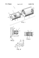
  • FIG. 1 is an exploded, perspective view of the integral speed sensor head.
  • FIG. 2 is a schematic view, partially in section, of the variable reluctance speed sensor head and the toothed exciter wheel.
  • FIG. 3 is a plan view of the exciter wheel and the sensor head and, schematically, shows the flux path and flux distribution of the speed sensor.
  • FIG. 4 shows the demagnetization curve for a magnet of the type utilized in the speed sensor and is useful in understanding the operation of the invention.
  • FIG. 1 shows an exploded, perspective view of the sensor head which cooperates with a toothed wheel constructed of a magnetically soft body, not shown in FIG. 1, to produce an output signal proportional to the speed of the wheel.
  • the sensing head shown generally at 1 includes a cup shaped housing made of a magnetically soft material.
  • the term magnetically soft material includes any shaped piece of ferromagnetic material which, once having been magnetized, is very easily demagnetized, i.e., once magnetized, only a slight coercive force is required to remove the resultant magnetism in the material.
  • the cup shaped housing 2 includes a cylindrical outer wall 3, a base 4 and a reentrant center post 5 which is integral with base and sidewalls of the housing 1.
  • Center post 5 is concentric with outer wall 3, and as will be described later, supports both a permanent magnet as well as a coil which is wound on a bobbin which fits around the center post. A voltage is induced in the coil as the flux passing through the center post changes with movement of a toothed wheel associated with the sensor head. Center post 5 is slightly shorter than outer wall 3 in order to allow sufficient space for mounting a thin, disc shaped, high energy rare earth magnet shown generally at 6.
  • Magnet 6 is securely attached to the end of the center post either by brazing or by means of a high temperature, structural adhesive such as that manufactured and sold by the Loctite Corporation under its trade designation "Loctite.”
  • Magnet 6 is preferably a rare earth magnet such as samarium cobalt which has a coercive force (H c ) in the order of 8,0000 oersteds. Because of the high coercive force which is characteristic of rare earth magnets, and the corresponding high energy products such magnets have, a very thin, disc magnet, i.e., one in which the diameter is greater than the length so that the ratio L/D ⁇ 1/3 is used. It has been found that a magnet having a thickness of several hundredths of an inch is all that is required to drive flux across the air gap and produce a useful signal in the sensor output coil.
  • a sensing coil is shown generally at 7 and consists of an insulating bobbin 8 which supports a winding 9.
  • Bobbin 8 has a central passage or opening 10 which is slightly larger than the diameter of center post 5. This allows the bobbin to be mounted on post 5 when the sensor is in the assembled state and one end of bobbin 8 is fastened to base 4 by an adhesive such as "Loctite.”
  • Output leads 11 from winding 9 pass through an opening 12 in the base of the housing 2 to bring the coil leads to the exterior of the sensing head for connection to a suitable remote signal processing and display circuit.
  • the bobbin may be dispensed with and the winding placed directly on the core over an intervening insulating layer.
  • housing 2 consists of a soft magnetic material, it can be seen that outer wall 3 provides return path for flux driven across the air gap and into a moving member such as toothed exciter wheel, not shown. Since the outer housing is in close proximity to and effectively surrounds center post 5 and permanent magnet 6 on all sides but that exposed to exciter wheel, it will also be apparent that the permanent magnet is shielded from the influence of any magnetic materials or fields positioned outside or adjacent to the housing and any such magnetic materials will have no effect on the sensor.
  • FIG. 2 shows the sensor head 1 positioned adjacent to a toothed exciter wheel 14 which is attached to and driven by a moving member, the speed of which is to be sensed.
  • Wheel 14 is fabricated from a magnetically soft material and consists of a main body 15 and a plurality of teeth or lobes 16.
  • Permanent magnet 6, which is fixed to the free end of center post 5, is thus positioned adjacent to wheel 14 so that a small air gap 17 exists between the permanent magnet and exciter wheel 14.
  • Coil 10 which is positioned on and surrounds center post 5 has a voltage induced therein which is proportional to the reluctance (or, conversely the permeance) of the magnetic path consisting of permanent magnet 6, air gap 17, exciter wheel 14, sidewalls 3, base 4 and center post 5 which constitute the magnetic return path for the flux driven across the air gap by magnet 6.
  • FIG. 3 which is a plan view of the sensing head and the wheel
  • the magnetic flux shown by the arrows 19 passes across the air gap 17 into wheel 14 and then back across the air gap into sidewalls 3 and then through base 4 and center post 5 back to the permanent magnet 6.
  • the sensor head forms an integral magnetic return path and surrounds the center post and the permanent magnet, it can be seen that the presence of any ferromagnetic material outside of the sensing head has virtually no effect on the functioning of the speed sensor head. Because of the shielding effect of the housing, it can be seen therefore that the speed sensor head is small, compact, and can be positioned closely to the toothed exciter wheel.
  • the permanent magnet is a very thin disc, the stresses on the interface between the center post and the magnitude of vibration and thermal coefficients of expansion of the two materials is also minimized.
  • the mechanical integrity of the center post flux return path and the primary magnet is therefore easily maintained thereby avoiding changes in the sensitivity of the device under conditions of vibration and high temperature.
  • FIG. 4 shows a typical demagnetization curve for a cobalt-samarium magnetic material and is useful in understanding the manner in which the system operates.
  • Demagnetization curve 20 shown in FIG. 4 is part of the hysteresis curve of the particular magnetic material and shows the relationship between the induction B in Gauss, plotted along the ordinate, and the magnetizing force H in oersteds, plotted along the abscissa.
  • Demagnetization curve 20 has a residual induction value B R (residual induction is defined as the magnetic induction corresponding to zero magnetizing force in a given magnetic material, i.e., the induction left in the magnet when H goes to zero).
  • the coercive force of the magnet is the magnetizing force required to reduce the induction to zero in magnetic material, i.e., 8000 oersteds for samarium cobalt. Once this magnetization force is removed, the magnetic induction springs back up the demagnetization curve 20 to some point which is a junction of the circuit permeability. For samarium cobalt magnet material, the magnetization force required to completely demagnetize the magnet is some much higher level, following a so-called intrinsic demagnetization curve, not shown.
  • the actual speed sensor magnetic circuit operating points X and Y are dependent on the wheel position since this cyclically varies the air gap. That is, the air gap is small when a tooth on the wheel is directly in front of the permanent magnet and as a result, the reluctance of the magnetic path is low. When the lands between the teeth are in front of the magnet, the air gap and path reluctance is increased and the permeability is decreased. Points X and Y are defined by the intersection of the load lines 21 and 22 with the demagnetization curve.
  • Load line 21 represents the operating condition of the sensor head and the exciter wheel with a tooth positioned directly in front of the permanent magnet, i.e., a very small air gap and low reluctance
  • load line 22 represents the operating conditions with the permanent magnet facing the areas between the teeth, i.e., to a very large air gap and hence, a very high reluctance path.
  • the actual slopes of the individual load lines and hence the actual operating points and values of induction B are determined not only by the dimension of the air gap but also by such items as the length and diameter of the magnet and the magnetic permeability of the remainder of the path including leakage.
  • the objective is to obtain a useful output signal having a peak-to-peak amplitude sufficiently large for easy sensing and signal processing, while at the same time, minimizing the size of the permanent magnet and the associated magnetic path in order to permit the manufacture of a small, compact sensor head.
  • a sensor head as shown in FIGS. 1 through 3 was constructed using a cup shaped housing of low carbon cold rolled steel which was one (1.0) inch long with an outer diameter of 0.70 inches.
  • a disc shaped, cobalt-samarium, permanent magnet, having a diameter (D) of 0.150 inches and a thickness (L) of 0.050 inches was cemented to the end of the center post and a coil comprising 4600 turns of 0.004 inch diameter wire was wound on a bobbin and positioned on the center post.
  • the air gap between the exciter wheel teeth and the permanent magnet was set at 0.044 inches and a 3 inch diameter wheel having teeth was rotated at 1400 rpm and the voltage induced in the coil was measured to determine whether a sensor of this size would produce a signal of sufficient amplitude to be useful in a speed measuring system.
  • the output signal from the coil was a generally sinusoidal voltage having peak-to-peak value of 3.0 volts. This showed that a sensor one inch long and less than 3/4 inch in diameter utilizing a magnet 0.150 inches in diameter and 0.05 inches thick produced a more than adequate output signal for use in a speed sensing system. It can be seen, therefore, that this integral magnetic circuit construction utilizing a rare earth, samarium-cobalt magnet positioned directly adjacent to rotating means, provides a small, compact, sensing head for a variable reluctance speed sensing device.
  • the sensing head is shown with a cylindrical or cup shaped housing having a center post extending into the middle thereof.
  • the instant invention is however, not limited to such a cylindrical shape since it will function equally well even though the outer walls are not cylindrical. That is, the housing may be of a configuration in which there are two rectangular outer walls, base and a coil and magnet supporting center post section extending between the two outer walls. In this arrangement while there is a little end leakage, the outer walls provide the flux return path and still effectively shield the permanent magnet from external magnetic effects, while yet permitting an integral construction which is compact and small.
  • One specific variation involves the use of two sensor elements, side-by-side, in one head assembly for dual output where it is highly desirable to minimize mutual coupling. This design problem is easily solved using the sensor approach described herein because of its inherent shielding qualities.

Landscapes

  • Physics & Mathematics (AREA)
  • General Physics & Mathematics (AREA)
  • Transmission And Conversion Of Sensor Element Output (AREA)

Abstract

A compact, highly efficient, integral construction for a speed sensor is described which, in a preferred embodiment, utilizes a cup shaped magnetically soft body or housing as an integral core, sheath and flux return path for a rare earth permanent magnet. A reentrant center post is positioned within the cup shaped sensor housing and a thin disc shaped, rare earth permanent magnet is secured to the free end of the center post. The magnet is thus positioned directly adjacent to a rotating toothed gear, the speed of which is to be sensed but is shielded magnetically from extraneous magnetic effects because it is positioned in the housing. As the toothed wheel rotates past the magnet, the reluctance of the magnetic path varies with the varying air gap. The flux level generated by the thin magnet varies correspondingly and an AC signal is generated in a coil mounted on the center post. By positioning the high coercive force, rare earth magnet directly adjacent to the wheel and providing a direct return path from the wheel teeth to the sidewalls of the cup shaped housing the magnet, a very compact and efficient construction is made possible.

Description

This invention relates to a variable reluctance speed sensor and more particularly, to a small, compact, integrally constructed sensing head utilizing a shielded high energy, rare earth permanent magnet.
Variable reluctance speed sensors for measuring the speed of a rotating device are well-known and have been in use for many years. Such prior art variable reluctance speed sensors, a typical version of which is shown in FIG. 6 of U.S. Pat. No. 3,614,615 entitled "Railway Vehicle Speed Indicating System," include a permanent magnet which is attached to one end of an elongated core made of a soft magnetic material which projects outwardly from the magnet toward a rotating member. The permanent magnet produces a field which drives flux through the core and across the air gap between the end of the core and a toothed wheel or other body. As the wheel rotates, the reluctance of the magnetic circuit varies as the teeth pass by the core. Thus, the core field is modulated producing an AC voltage in a coil positioned around the core with the frequency of the voltage being directly related to the speed of the exciter wheel.
Variable reluctance speed sensors of the type just described and shown in the aforementioned patent, suffer from a number of shortcomings which limit the utility of these devices. One of the shortcomings is that with hitherto available permanent magnetic materials such as iron, cobalt, nickel alloys, of the type sold under the trade designation "ALNICO" or cobalt steels, or platinum-cobalt alloys or chrome steels, the sensor permanent magnet has to be fairly large in order to drive enough flux through the core and across the air gap to produce an adequate output signal. Consequently, these prior art variable reluctance speed sensors tend to be long. For certain space limited applications, such as on aircraft engines, this can be a definite handicap.
In addition, because a fairly long core is attached to a fairly long magnet, use of the sensor in a vibratory environment can present problems since vibration introduces stresses on the long cantilevered core resulting in poor mechanical coupling between the magnet and the core. This introduces additional air gaps into the magnet path and often results in significant vibration induced output errors. Similarly, thermal expansion stresses can also produce poor mechanical coupling between the magnet and core which results in an increase in the reluctance (or conversely a decrease in the permeance) of the magnetic circuit. Thus, if the sensor is to be used in a high temperature environment such as a jet aircraft where the temperature level is typically 400° to 500° F., there can be substantial problems which require care both in the design and in assembly and manufacture of the sensor to minimize stresses due to thermal expansion so that integrity of the joint between the magnet and the core is maintained.
Yet another problem often encountered with prior art, variable reluctance sensing devices is their sensitivity to any ferromagnetic materials in the vicinity of the sensor. That is, prior art devices normally have an air return path in the sense that the return flux either comes directly through air or through a non-ferromagnetic sheathing (which is the magnetic equivalent of air). Hence, problems are encountered whenever the sensor has to be mounted near anything which is made of a ferromagnetic material. When the sensor is located near such a ferromagnetic material, the ferromagnetic material acts as a flux shorting mechanism thereby diverting the flux from the sensing magnetic path and introducing errors into the reading by affecting and degrading the output sensitivity.
Furthermore, many of the permanent magnetic materials hitherto available have fairly low coercive forces, i.e., the force required to demagnetize the material is low. The design of the sensors in terms of air gaps, magnet diameters and length, is therefore quite critical to avoid inadvertent "knockdown" or demagnetization of the magnet.
Consequently, a need exists for an improved, variable reluctance sensor which is small and compact, which is not susceptible to thermal expansion and vibration induced mechanical stresses and which, at the same time, provides inherent self-shielding so that ferromagnetic materials in the vicinity of the sensor have no measurable effect on performance.
Applicant has found that all of these desirable qualities and characteristics may be provided in a sensor configuration which uses a thin, (i.e., diameter> length) disc shaped rare earth, permanent magnet positioned in a housing of magnetically soft material which surrounds the magnet and acts as an integral, core, sheath and flux return structure. By virtue of this configuration, a closely controlled flux return path is established which has the advantage of shielding the permanent magnet from the effects of extraneous ferromagnetic materials.
It is therefore a principal purpose of the instant application to provide a variable reluctance, speed sensor which provides an integral, magnetically shielded housing structure for the permanent magnet.
Yet another objective of the invention is to provide a small, compact variable reluctance, sensor which is simple in construction, and is not subject to thermal and vibration induced mechanical problems.
Yet another objective of the invention is to provide a variable reluctance, speed sensor having a high energy magnet positioned directly adjacent to the rotating member.
Yet another objective of the invention is to provide a variable reluctance, speed sensor having an integral core and flux return construction to shield the permanent magnet forming part of the sensor from external fields.
Yet other objectives of the invention will become apparent as the description thereof proceeds.
The various advantages of the instant invention are realized, in a preferred embodiment thereof, in a construction comprising a cup shaped, integral sensor housing formed of a magnetically soft material. A reentrant center post, concentric with the outer walls of the housing, extends from the base of the housing. A thin, disc shaped, rare earth, permanent magnet, such as samarium cobalt, for example, is firmly affixed to the outer or free end of the post. The rare earth permanent magnet is thus positioned directly adjacent to a toothed exciter wheel which is attached to the object, the speed of which is to be measured. A sensing coil is positioned around the center post and a voltage is induced in the coil as the teeth or lobes of the exciter wheel rotate past the rare earth magnet. The outer walls of the housing which surround the center post and the magnet, provide a magnetic return path for the flux passing from the magnet across the air gap and into the exciter wheel. The housing thus shields the permanent magnet so that external magnetic fields or the presence of extraneous ferromagnetic materials near the sensor have no measurable effect on the output of the sensor. By use of a rare earth magnet and the integral housing structure, a very small, compact, highly sensitive variable speed sensor configuration is made possible.
The novel features which are believed to be characteristic of this invention are set forth with particularity in the appended claims. The invention itself, however, both as to its organization and mode of operation, together with further objectives and advantages, may best be understood by reference to the following description taken in connection with the accompanying drawings in which:
FIG. 1 is an exploded, perspective view of the integral speed sensor head.
FIG. 2 is a schematic view, partially in section, of the variable reluctance speed sensor head and the toothed exciter wheel.
FIG. 3 is a plan view of the exciter wheel and the sensor head and, schematically, shows the flux path and flux distribution of the speed sensor.
FIG. 4 shows the demagnetization curve for a magnet of the type utilized in the speed sensor and is useful in understanding the operation of the invention.
FIG. 1 shows an exploded, perspective view of the sensor head which cooperates with a toothed wheel constructed of a magnetically soft body, not shown in FIG. 1, to produce an output signal proportional to the speed of the wheel. The sensing head shown generally at 1, includes a cup shaped housing made of a magnetically soft material. The term magnetically soft material includes any shaped piece of ferromagnetic material which, once having been magnetized, is very easily demagnetized, i.e., once magnetized, only a slight coercive force is required to remove the resultant magnetism in the material. The cup shaped housing 2 includes a cylindrical outer wall 3, a base 4 and a reentrant center post 5 which is integral with base and sidewalls of the housing 1. Center post 5 is concentric with outer wall 3, and as will be described later, supports both a permanent magnet as well as a coil which is wound on a bobbin which fits around the center post. A voltage is induced in the coil as the flux passing through the center post changes with movement of a toothed wheel associated with the sensor head. Center post 5 is slightly shorter than outer wall 3 in order to allow sufficient space for mounting a thin, disc shaped, high energy rare earth magnet shown generally at 6. Disc magnet 6 is securely attached to the end of the center post either by brazing or by means of a high temperature, structural adhesive such as that manufactured and sold by the Loctite Corporation under its trade designation "Loctite." Magnet 6 is preferably a rare earth magnet such as samarium cobalt which has a coercive force (Hc) in the order of 8,0000 oersteds. Because of the high coercive force which is characteristic of rare earth magnets, and the corresponding high energy products such magnets have, a very thin, disc magnet, i.e., one in which the diameter is greater than the length so that the ratio L/D < 1/3 is used. It has been found that a magnet having a thickness of several hundredths of an inch is all that is required to drive flux across the air gap and produce a useful signal in the sensor output coil.
A sensing coil is shown generally at 7 and consists of an insulating bobbin 8 which supports a winding 9. Bobbin 8 has a central passage or opening 10 which is slightly larger than the diameter of center post 5. This allows the bobbin to be mounted on post 5 when the sensor is in the assembled state and one end of bobbin 8 is fastened to base 4 by an adhesive such as "Loctite." Output leads 11 from winding 9 pass through an opening 12 in the base of the housing 2 to bring the coil leads to the exterior of the sensing head for connection to a suitable remote signal processing and display circuit.
It will be understood that the bobbin may be dispensed with and the winding placed directly on the core over an intervening insulating layer. Because housing 2 consists of a soft magnetic material, it can be seen that outer wall 3 provides return path for flux driven across the air gap and into a moving member such as toothed exciter wheel, not shown. Since the outer housing is in close proximity to and effectively surrounds center post 5 and permanent magnet 6 on all sides but that exposed to exciter wheel, it will also be apparent that the permanent magnet is shielded from the influence of any magnetic materials or fields positioned outside or adjacent to the housing and any such magnetic materials will have no effect on the sensor.
FIG. 2 shows the sensor head 1 positioned adjacent to a toothed exciter wheel 14 which is attached to and driven by a moving member, the speed of which is to be sensed. Wheel 14 is fabricated from a magnetically soft material and consists of a main body 15 and a plurality of teeth or lobes 16. Permanent magnet 6, which is fixed to the free end of center post 5, is thus positioned adjacent to wheel 14 so that a small air gap 17 exists between the permanent magnet and exciter wheel 14. Coil 10 which is positioned on and surrounds center post 5 has a voltage induced therein which is proportional to the reluctance (or, conversely the permeance) of the magnetic path consisting of permanent magnet 6, air gap 17, exciter wheel 14, sidewalls 3, base 4 and center post 5 which constitute the magnetic return path for the flux driven across the air gap by magnet 6.
As can be seen in FIG. 3 which is a plan view of the sensing head and the wheel, the magnetic flux shown by the arrows 19 passes across the air gap 17 into wheel 14 and then back across the air gap into sidewalls 3 and then through base 4 and center post 5 back to the permanent magnet 6. Since the sensor head forms an integral magnetic return path and surrounds the center post and the permanent magnet, it can be seen that the presence of any ferromagnetic material outside of the sensing head has virtually no effect on the functioning of the speed sensor head. Because of the shielding effect of the housing, it can be seen therefore that the speed sensor head is small, compact, and can be positioned closely to the toothed exciter wheel.
Since the permanent magnet is a very thin disc, the stresses on the interface between the center post and the magnitude of vibration and thermal coefficients of expansion of the two materials is also minimized. The mechanical integrity of the center post flux return path and the primary magnet is therefore easily maintained thereby avoiding changes in the sensitivity of the device under conditions of vibration and high temperature.
FIG. 4 shows a typical demagnetization curve for a cobalt-samarium magnetic material and is useful in understanding the manner in which the system operates.
Demagnetization curve 20 shown in FIG. 4 is part of the hysteresis curve of the particular magnetic material and shows the relationship between the induction B in Gauss, plotted along the ordinate, and the magnetizing force H in oersteds, plotted along the abscissa. Demagnetization curve 20 has a residual induction value BR (residual induction is defined as the magnetic induction corresponding to zero magnetizing force in a given magnetic material, i.e., the induction left in the magnet when H goes to zero). The coercive force of the magnet, shown at Hc, is the magnetizing force required to reduce the induction to zero in magnetic material, i.e., 8000 oersteds for samarium cobalt. Once this magnetization force is removed, the magnetic induction springs back up the demagnetization curve 20 to some point which is a junction of the circuit permeability. For samarium cobalt magnet material, the magnetization force required to completely demagnetize the magnet is some much higher level, following a so-called intrinsic demagnetization curve, not shown.
The actual speed sensor magnetic circuit operating points X and Y are dependent on the wheel position since this cyclically varies the air gap. That is, the air gap is small when a tooth on the wheel is directly in front of the permanent magnet and as a result, the reluctance of the magnetic path is low. When the lands between the teeth are in front of the magnet, the air gap and path reluctance is increased and the permeability is decreased. Points X and Y are defined by the intersection of the load lines 21 and 22 with the demagnetization curve. Load line 21 represents the operating condition of the sensor head and the exciter wheel with a tooth positioned directly in front of the permanent magnet, i.e., a very small air gap and low reluctance, and load line 22 represents the operating conditions with the permanent magnet facing the areas between the teeth, i.e., to a very large air gap and hence, a very high reluctance path. The actual slopes of the individual load lines and hence the actual operating points and values of induction B are determined not only by the dimension of the air gap but also by such items as the length and diameter of the magnet and the magnetic permeability of the remainder of the path including leakage.
As exciter wheel 15 rotates, the thin permanent magnet 6 initially encounters a relatively low reluctance path when tooth 16 is directly opposite the magnet and produces a flux or induction level Bx equivalent to the operating point X on the curve as represented by load line 21. As the tooth 16 rotates away, reluctance increases, since the air path is now substantially longer. The operating conditions are now represented load line 22 and the operating point is point Y on curve and produces a flux or induction level equivalent to By. Since this changing flux level is coupled through center post 5, an AC signal is generated in coil 10 which has a frequency directly proportional to the exciter wheel speed.
The objective, of course, is to obtain a useful output signal having a peak-to-peak amplitude sufficiently large for easy sensing and signal processing, while at the same time, minimizing the size of the permanent magnet and the associated magnetic path in order to permit the manufacture of a small, compact sensor head. By utilizing the construction herein and shown in FIGS. 1 through 3, i.e., with a rare earth magnet positioned directly adjacent to the exciter teeth and an integral magnetic return path which shields the magnet, it has been found that a very small and compact device may be constructed which functions accurately and effectively.
A sensor head as shown in FIGS. 1 through 3 was constructed using a cup shaped housing of low carbon cold rolled steel which was one (1.0) inch long with an outer diameter of 0.70 inches. A disc shaped, cobalt-samarium, permanent magnet, having a diameter (D) of 0.150 inches and a thickness (L) of 0.050 inches was cemented to the end of the center post and a coil comprising 4600 turns of 0.004 inch diameter wire was wound on a bobbin and positioned on the center post. The air gap between the exciter wheel teeth and the permanent magnet was set at 0.044 inches and a 3 inch diameter wheel having teeth was rotated at 1400 rpm and the voltage induced in the coil was measured to determine whether a sensor of this size would produce a signal of sufficient amplitude to be useful in a speed measuring system. In running the wheel at 1400 rpm and with the device constructed as described above, the output signal from the coil was a generally sinusoidal voltage having peak-to-peak value of 3.0 volts. This showed that a sensor one inch long and less than 3/4 inch in diameter utilizing a magnet 0.150 inches in diameter and 0.05 inches thick produced a more than adequate output signal for use in a speed sensing system. It can be seen, therefore, that this integral magnetic circuit construction utilizing a rare earth, samarium-cobalt magnet positioned directly adjacent to rotating means, provides a small, compact, sensing head for a variable reluctance speed sensing device.
In the preferred embodiment illustrated in FIGS. 1 through 3, the sensing head is shown with a cylindrical or cup shaped housing having a center post extending into the middle thereof. The instant invention is however, not limited to such a cylindrical shape since it will function equally well even though the outer walls are not cylindrical. That is, the housing may be of a configuration in which there are two rectangular outer walls, base and a coil and magnet supporting center post section extending between the two outer walls. In this arrangement while there is a little end leakage, the outer walls provide the flux return path and still effectively shield the permanent magnet from external magnetic effects, while yet permitting an integral construction which is compact and small.
One specific variation involves the use of two sensor elements, side-by-side, in one head assembly for dual output where it is highly desirable to minimize mutual coupling. This design problem is easily solved using the sensor approach described herein because of its inherent shielding qualities.
While a particular embodiment of the invention has been illustrated and described, it will be apparent that various modifications thereof may obviously be made both in the various instrumentalities and in the arrangement described without departing from the true spirit and scope of the invention as defined in appended claims.
Claims (9)

What is claimed as new and desired to be secured by Letters Patent of the United States is:
1. A variable reluctance speed sensing device for measuring the speed of a moving element including, in combination:
a. a thin, disc shaped, rare earth permanent magnet of thickness L and diameter D for producing magnetic flux for passage through a moving member,
b. an integral housing formed of a ferromagnetic material to provide a return path for the magnetic flux, comprising:
1. wall means to provide a return flux path for the flux from said magnet after passage through a moving element,
2. a base member connecting said wall means,
3. a core member extending from said base and positioned re-entrantly within said wall means for supporting said magnet at the free end thereof whereby said magnet may be positioned directly adjacent to a moving member to establish a flux path from said magnet across an air gap to a moving member and back through said housing; said re-entrant core member being positioned within said walls to shield said core and said magnet from external magnetic effects,
4. a sensing coil supported on said core member for producing a signal due to flux variations in said housing and said core due to a moving member.
2. The variable reluctance speed sensing device of claim 1 wherein said magnet is a samarium-cobalt or other high coercive force magnet, and the ratio of L/D of said magnet is no greater than 1/3.
3. The variable reluctance speed sensing device according to claim 1 wherein said wall means completely surround said core member.
4. A variable reluctance speed sensing device according to claim 3 wherein said integral housing is cup shaped and said wall means is of a cylindrical configuration.
5. A variable reluctance speed sensing system including:
a. a thin, disc shaped, rate earth permanent magnet of thickness L and diameter D for producing magnetic flux.
b. a moving member having protuberances to vary the air gap relative to said magnet whereby the reluctance of the associated magnetic path and the magnetic induction in said path is varied,
c. an integral housing for said magnet formed of a ferromagnetic material to provide a magnetic flux return path for the flux from said magnet and said moving member comprising:
1. wall means to provide a return flux path for the flux from said magnet after passage through said moving member;
2. a base member connecting said wall means,
3. a core member extending from said base and positioned re-entrantly within said wall means for supporting said magnet at its free end whereby said magnet is positioned directly adjacent to said moving member to establish a flux path from said magnet across an air gap to said moving member and back, the said air gap being varied as the member rotates and the protuberances move by said magnet, said re-entrant core member being positioned within said wall means to shield said core and said magnet from external magnetic effects.
4. a sensing coil supported on said core for producing a signal voltage therein due to flux variations produced by said moving member.
6. A variable reluctance speed sensing system according to claim 5 wherein said magnet is a samarium cobalt or high coercive force magnet and the ratio of L/D is no greater than 1/3.
7. The variable reluctance speed sensing system according to claim 5 wherein said wall means completely surround said core means to shield said core from the action of external magnetic effects.
8. The variable reluctance speed sensing system according to claim 7 wherein said integral housing is cup shaped, then said wall means is of a cylindrical configuration.
9. A variable reluctance speed sensing system according to claim 8 wherein said moving member comprises a wheel having a plurality of teeth.
US05/665,047 1976-03-08 1976-03-08 Variable reluctance speed sensor of integral construction utilizing a shielded high coercive force rare earth magnet positioned directly adjacent the sensing rotating element Expired - Lifetime US4045738A (en)

Priority Applications (3)

Application Number Priority Date Filing Date Title
US05/665,047 US4045738A (en) 1976-03-08 1976-03-08 Variable reluctance speed sensor of integral construction utilizing a shielded high coercive force rare earth magnet positioned directly adjacent the sensing rotating element
FR7706089A FR2344022A1 (en) 1976-03-08 1977-03-02 VARIABLE RELUCTANCE SPEED SENSOR
GB9808/77A GB1516078A (en) 1976-03-08 1977-03-08 Variable reluctance speed sensor

Applications Claiming Priority (1)

Application Number Priority Date Filing Date Title
US05/665,047 US4045738A (en) 1976-03-08 1976-03-08 Variable reluctance speed sensor of integral construction utilizing a shielded high coercive force rare earth magnet positioned directly adjacent the sensing rotating element

Publications (1)

Publication Number Publication Date
US4045738A true US4045738A (en) 1977-08-30

Family

ID=24668488

Family Applications (1)

Application Number Title Priority Date Filing Date
US05/665,047 Expired - Lifetime US4045738A (en) 1976-03-08 1976-03-08 Variable reluctance speed sensor of integral construction utilizing a shielded high coercive force rare earth magnet positioned directly adjacent the sensing rotating element

Country Status (3)

Country Link
US (1) US4045738A (en)
FR (1) FR2344022A1 (en)
GB (1) GB1516078A (en)

Cited By (47)

* Cited by examiner, † Cited by third party
Publication number Priority date Publication date Assignee Title
US4198006A (en) * 1978-10-30 1980-04-15 Sperry Corporation Magnetic clearance sensor
US4205797A (en) * 1978-10-30 1980-06-03 Sperry Corporation Magnetic clearance sensor
WO1981002345A1 (en) * 1980-02-04 1981-08-20 Caterpillar Tractor Co Velocity sensing system
US4289722A (en) * 1980-07-28 1981-09-15 General Motors Corporation Method of potting magnetic speed pickups
US4314202A (en) * 1978-08-07 1982-02-02 Shigeo Okubo Flexural vibration sensor with magnetic field generating and sensing
US4355364A (en) * 1980-02-04 1982-10-19 Caterpillar Tractor Co. Velocity sensing system
US4366405A (en) * 1979-08-23 1982-12-28 Papst Motoren Kg Tachogenerator having stray flux cancelling output coils
US4384252A (en) * 1979-05-11 1983-05-17 The Bendix Corporation Cup shaped magnetic pickoff for use with a variable reluctance motion sensing system
US4471303A (en) * 1978-08-07 1984-09-11 Design Professionals Financial Corporation Flexural vibration transducer with magnetic field generating
US4618823A (en) * 1982-09-30 1986-10-21 Werner Turck Gmbh & Co. Kg Inductive proximity switch having an oscillator magnetic core and a permanent magnet forming a saturation-sensitive magnetization area
US4670715A (en) * 1983-01-28 1987-06-02 Caterpillar Inc. Frictionally supported gear tooth sensor with self-adjusting air gap
US4721864A (en) * 1985-12-05 1988-01-26 Alfred Teves Gmbh & Co. Ohg Inductive pulse generator
DE3701467A1 (en) * 1987-01-20 1988-07-28 Elektroteile Gmbh Magneto-electrical velocity pick up
US4904936A (en) * 1986-03-03 1990-02-27 Emhart Industries, Inc. Automotive wheel speed sensor including ferromagnetic flux carrying cup closing an opening in the wheel bearing housing
US4916295A (en) * 1987-06-12 1990-04-10 Inter Innovation Ab Document detecting arrangement
US4922197A (en) * 1988-08-01 1990-05-01 Eaton Corporation High resolution proximity detector employing magnetoresistive sensor disposed within a pressure resistant enclosure
US4937522A (en) * 1988-08-29 1990-06-26 Eaton Corporation Speed sensor pickup assembly with slotted magnet
US4947035A (en) * 1988-08-08 1990-08-07 Cornell Research Foundation, Inc. Fiber optic transducer using faraday effect
US4954775A (en) * 1986-03-03 1990-09-04 Emhart Industries Inc. Automotive wheel speed sensor assembly with multipole rotor mounted on wheel bearing spindle
US5160886A (en) * 1991-02-14 1992-11-03 Carlen Controls, Inc. Permanent magnet resolver for producing a resolver-to-digital converter compatible output
US5278496A (en) * 1992-05-22 1994-01-11 Component Sales & Consultants, Inc. High output and environmentally impervious variable reluctance sensor
US5486758A (en) * 1993-10-06 1996-01-23 Kelsey-Hayes Company Integral variable reluctance speed sensor
US5507089A (en) * 1992-05-22 1996-04-16 Component Sales & Consultants, Inc. Method of assembly of a variable reluctance sensor
US5563510A (en) * 1995-04-11 1996-10-08 Component Sales & Consultants, Inc. Variable reluctance sensor having hermetically sealed housing and damping element
US5606254A (en) * 1995-10-19 1997-02-25 General Motors Corporation Rotation sensor employing coil wound on assembly of a core interposed between two magnets
US5996745A (en) * 1997-05-15 1999-12-07 K-2 Corporation Piezoelectric shock absorber valve
US6026939A (en) * 1997-05-15 2000-02-22 K2 Bike Inc. Shock absorber with stanchion mounted bypass damping
US6164424A (en) * 1997-05-15 2000-12-26 K2 Bike Inc. Shock absorber with bypass damping
US6244398B1 (en) 1997-05-15 2001-06-12 K2 Bike Inc. Shock absorber with variable bypass damping
US6529008B1 (en) 1998-04-27 2003-03-04 Moustafa Abdel Kader Mohamed Electromagnetic induction coil sensor
US6590385B2 (en) * 2001-07-06 2003-07-08 Delphi Technologies, Inc. Variable reluctance sensor assembly with magnetic spool
US20050017586A1 (en) * 2003-07-09 2005-01-27 Aktiebolaget Skf Bearing assembly for the hub of a motor vehicle wheel
US7023205B1 (en) * 2000-08-01 2006-04-04 General Dynamics Advanced Information Systems, Inc. Eddy current sensor capable of sensing through a conductive barrier
US20080211610A1 (en) * 2005-10-06 2008-09-04 Micro Motion, Inc. Magnet Assembly
US20100308809A1 (en) * 2007-10-18 2010-12-09 Peter Houldley Pipeline geometry sensor
EP2400307A1 (en) * 2010-06-22 2011-12-28 Weston Aerospace Limited Speed or torque probe for gas turbine engines
CN105158498A (en) * 2015-09-29 2015-12-16 哈尔滨东安发动机(集团)有限公司 Aviation rotating speed sensor
US20160108842A1 (en) * 2014-10-16 2016-04-21 Continental Automotive France Method for communicating a malfunction of a system for measuring speed and direction of rotation of a rotary shaft
CN102032936B (en) * 2005-10-06 2016-06-29 微动公司 Magnet apparatus
US10459543B2 (en) 2017-03-23 2019-10-29 Microsoft Technology Licensing, Llc Input device using magnetic field for input detection
WO2020036859A1 (en) * 2018-08-12 2020-02-20 Revvo Technologies, Inc. Tire sensor device
US10889367B2 (en) 2017-04-24 2021-01-12 Pratt & Whitney Canada Corp. Feedback system for pitch-adjustable blades of aircraft bladed rotor
US10976221B2 (en) 2018-01-09 2021-04-13 Weston Aerospace Limited Magnetic gas turbine sensor
US11002280B2 (en) * 2017-07-23 2021-05-11 Adam Esberger Method and system for monitoring moving elements
US11312611B2 (en) * 2019-05-13 2022-04-26 Lg Electronics Inc. Hydrogen water generator
US20220392680A1 (en) * 2021-06-02 2022-12-08 Canon Kabushiki Kaisha Electronic apparatus
US11913783B1 (en) 2019-11-22 2024-02-27 Cypress In-Line Inspection, LLC Geometry sensor for inline inspection tool

Families Citing this family (1)

* Cited by examiner, † Cited by third party
Publication number Priority date Publication date Assignee Title
FR2585840A1 (en) * 1985-08-01 1987-02-06 Sato Electronique Sa Speed sensor

Citations (5)

* Cited by examiner, † Cited by third party
Publication number Priority date Publication date Assignee Title
US3633138A (en) * 1968-11-20 1972-01-04 Max Baermann Temperature-compensated permanent magnet
US3671893A (en) * 1970-11-18 1972-06-20 Gen Electric Magnetic latch and switch using cobalt-rare earth permanent magnets
US3826985A (en) * 1971-06-04 1974-07-30 Motorola Inc Self-powered tachometer circuit
US3881127A (en) * 1973-11-01 1975-04-29 Us Navy Bucking samarium cobalt magnets for crossed field devices
US3929519A (en) * 1973-10-29 1975-12-30 Gen Electric Flexible cobalt-rare earth permanent magnet product and method for making said product

Family Cites Families (4)

* Cited by examiner, † Cited by third party
Publication number Priority date Publication date Assignee Title
US3626226A (en) * 1970-06-01 1971-12-07 Bendix Corp Wheel speed sensor for an adaptive braking system
FR2245930A1 (en) * 1973-07-26 1975-04-25 Peugeot & Renault Magnetic position sensor - has magnetic fiel field sensitive semiconductor element and samarium cobalt magnet
FR2252573A1 (en) * 1973-11-23 1975-06-20 Ferodo Sa Detection of angular speed of motor vehicle wheel - is electrically signalled from coil sensing teeth on disc
US3854556A (en) * 1973-12-27 1974-12-17 Eaton Corp Anti-skid system having improved sensor

Patent Citations (5)

* Cited by examiner, † Cited by third party
Publication number Priority date Publication date Assignee Title
US3633138A (en) * 1968-11-20 1972-01-04 Max Baermann Temperature-compensated permanent magnet
US3671893A (en) * 1970-11-18 1972-06-20 Gen Electric Magnetic latch and switch using cobalt-rare earth permanent magnets
US3826985A (en) * 1971-06-04 1974-07-30 Motorola Inc Self-powered tachometer circuit
US3929519A (en) * 1973-10-29 1975-12-30 Gen Electric Flexible cobalt-rare earth permanent magnet product and method for making said product
US3881127A (en) * 1973-11-01 1975-04-29 Us Navy Bucking samarium cobalt magnets for crossed field devices

Non-Patent Citations (1)

* Cited by examiner, † Cited by third party
Title
Measurement of Magnetic Properties of Cobalt-Rare Earth Permanent Magnets, M. G. Benz & D. Luther Martin, IEEE Trans. on Magnetics, vol. Mag. 7, No. 2, June 1971, pp. 285-291.

Cited By (57)

* Cited by examiner, † Cited by third party
Publication number Priority date Publication date Assignee Title
US4314202A (en) * 1978-08-07 1982-02-02 Shigeo Okubo Flexural vibration sensor with magnetic field generating and sensing
US4471303A (en) * 1978-08-07 1984-09-11 Design Professionals Financial Corporation Flexural vibration transducer with magnetic field generating
US4198006A (en) * 1978-10-30 1980-04-15 Sperry Corporation Magnetic clearance sensor
US4205797A (en) * 1978-10-30 1980-06-03 Sperry Corporation Magnetic clearance sensor
US4384252A (en) * 1979-05-11 1983-05-17 The Bendix Corporation Cup shaped magnetic pickoff for use with a variable reluctance motion sensing system
US4366405A (en) * 1979-08-23 1982-12-28 Papst Motoren Kg Tachogenerator having stray flux cancelling output coils
WO1981002345A1 (en) * 1980-02-04 1981-08-20 Caterpillar Tractor Co Velocity sensing system
US4355364A (en) * 1980-02-04 1982-10-19 Caterpillar Tractor Co. Velocity sensing system
US4289722A (en) * 1980-07-28 1981-09-15 General Motors Corporation Method of potting magnetic speed pickups
US4618823A (en) * 1982-09-30 1986-10-21 Werner Turck Gmbh & Co. Kg Inductive proximity switch having an oscillator magnetic core and a permanent magnet forming a saturation-sensitive magnetization area
US4670715A (en) * 1983-01-28 1987-06-02 Caterpillar Inc. Frictionally supported gear tooth sensor with self-adjusting air gap
US4721864A (en) * 1985-12-05 1988-01-26 Alfred Teves Gmbh & Co. Ohg Inductive pulse generator
US4954775A (en) * 1986-03-03 1990-09-04 Emhart Industries Inc. Automotive wheel speed sensor assembly with multipole rotor mounted on wheel bearing spindle
US4904936A (en) * 1986-03-03 1990-02-27 Emhart Industries, Inc. Automotive wheel speed sensor including ferromagnetic flux carrying cup closing an opening in the wheel bearing housing
DE3701467A1 (en) * 1987-01-20 1988-07-28 Elektroteile Gmbh Magneto-electrical velocity pick up
US4916295A (en) * 1987-06-12 1990-04-10 Inter Innovation Ab Document detecting arrangement
US4922197A (en) * 1988-08-01 1990-05-01 Eaton Corporation High resolution proximity detector employing magnetoresistive sensor disposed within a pressure resistant enclosure
US4947035A (en) * 1988-08-08 1990-08-07 Cornell Research Foundation, Inc. Fiber optic transducer using faraday effect
US4937522A (en) * 1988-08-29 1990-06-26 Eaton Corporation Speed sensor pickup assembly with slotted magnet
US5160886A (en) * 1991-02-14 1992-11-03 Carlen Controls, Inc. Permanent magnet resolver for producing a resolver-to-digital converter compatible output
US5278496A (en) * 1992-05-22 1994-01-11 Component Sales & Consultants, Inc. High output and environmentally impervious variable reluctance sensor
US5381089A (en) * 1992-05-22 1995-01-10 Component Sales & Consultants, Inc. High output and environmentally impervious variable reluctance sensor
US5507089A (en) * 1992-05-22 1996-04-16 Component Sales & Consultants, Inc. Method of assembly of a variable reluctance sensor
US5998988A (en) * 1992-05-22 1999-12-07 Component Sales & Consultants, Inc. High output and environmentally impervious variable reluctance sensor
US5486758A (en) * 1993-10-06 1996-01-23 Kelsey-Hayes Company Integral variable reluctance speed sensor
US5563510A (en) * 1995-04-11 1996-10-08 Component Sales & Consultants, Inc. Variable reluctance sensor having hermetically sealed housing and damping element
US5606254A (en) * 1995-10-19 1997-02-25 General Motors Corporation Rotation sensor employing coil wound on assembly of a core interposed between two magnets
US6026939A (en) * 1997-05-15 2000-02-22 K2 Bike Inc. Shock absorber with stanchion mounted bypass damping
US6164424A (en) * 1997-05-15 2000-12-26 K2 Bike Inc. Shock absorber with bypass damping
US6244398B1 (en) 1997-05-15 2001-06-12 K2 Bike Inc. Shock absorber with variable bypass damping
US5996745A (en) * 1997-05-15 1999-12-07 K-2 Corporation Piezoelectric shock absorber valve
US6529008B1 (en) 1998-04-27 2003-03-04 Moustafa Abdel Kader Mohamed Electromagnetic induction coil sensor
US7023205B1 (en) * 2000-08-01 2006-04-04 General Dynamics Advanced Information Systems, Inc. Eddy current sensor capable of sensing through a conductive barrier
US6590385B2 (en) * 2001-07-06 2003-07-08 Delphi Technologies, Inc. Variable reluctance sensor assembly with magnetic spool
KR101260071B1 (en) * 2003-07-09 2013-05-02 액티어보래깃 에스케이에프 A bearing assembly for the hub of a motor vehicle wheel
US20050017586A1 (en) * 2003-07-09 2005-01-27 Aktiebolaget Skf Bearing assembly for the hub of a motor vehicle wheel
CN100434920C (en) * 2003-07-09 2008-11-19 Skf公司 Bearing assemblies for use on wheel hubs of motor vehicles
US7164265B2 (en) * 2003-07-09 2007-01-16 Aktiebolaget Skf Bearing assembly with rotation sensing device
US20080211610A1 (en) * 2005-10-06 2008-09-04 Micro Motion, Inc. Magnet Assembly
CN102032936B (en) * 2005-10-06 2016-06-29 微动公司 Magnet apparatus
US8362864B2 (en) * 2005-10-06 2013-01-29 Micro Motion, Inc. Magnet assembly
US20100308809A1 (en) * 2007-10-18 2010-12-09 Peter Houldley Pipeline geometry sensor
GB2481414B (en) * 2010-06-22 2012-09-19 Weston Aerospace Ltd Speed or torque probe for gas turbine engines
EP2400307A1 (en) * 2010-06-22 2011-12-28 Weston Aerospace Limited Speed or torque probe for gas turbine engines
US20160108842A1 (en) * 2014-10-16 2016-04-21 Continental Automotive France Method for communicating a malfunction of a system for measuring speed and direction of rotation of a rotary shaft
US9739228B2 (en) * 2014-10-16 2017-08-22 Continental Automotive France Method for communicating a malfunction of a system for measuring speed and direction of rotation of a rotary shaft
CN105158498A (en) * 2015-09-29 2015-12-16 哈尔滨东安发动机(集团)有限公司 Aviation rotating speed sensor
US10459543B2 (en) 2017-03-23 2019-10-29 Microsoft Technology Licensing, Llc Input device using magnetic field for input detection
US10889367B2 (en) 2017-04-24 2021-01-12 Pratt & Whitney Canada Corp. Feedback system for pitch-adjustable blades of aircraft bladed rotor
US11002280B2 (en) * 2017-07-23 2021-05-11 Adam Esberger Method and system for monitoring moving elements
US10976221B2 (en) 2018-01-09 2021-04-13 Weston Aerospace Limited Magnetic gas turbine sensor
WO2020036859A1 (en) * 2018-08-12 2020-02-20 Revvo Technologies, Inc. Tire sensor device
US11946829B2 (en) * 2018-08-12 2024-04-02 Revvo Technologies, Inc. Tire sensor device
US11312611B2 (en) * 2019-05-13 2022-04-26 Lg Electronics Inc. Hydrogen water generator
US11913783B1 (en) 2019-11-22 2024-02-27 Cypress In-Line Inspection, LLC Geometry sensor for inline inspection tool
US20220392680A1 (en) * 2021-06-02 2022-12-08 Canon Kabushiki Kaisha Electronic apparatus
US11682511B2 (en) * 2021-06-02 2023-06-20 Canon Kabushiki Kaisha Electronic apparatus

Also Published As

Publication number Publication date
FR2344022A1 (en) 1977-10-07
GB1516078A (en) 1978-06-28
FR2344022B1 (en) 1983-09-09

Similar Documents

Publication Publication Date Title
US3932813A (en) Eddy current sensor
EP0215454B1 (en) Position detecting apparatus utilizing a magnetic sensor
US5814985A (en) Incremental sensor of speed and/or position for detecting low and null speeds
EP1538448A1 (en) Eddy current sensors
US4229696A (en) Sensor for measuring magnetic field changes
US3855525A (en) Angular velocity sensor
JPH01187424A (en) Torque sensor
US5229715A (en) Variable reluctance sensor for electromagnetically sensing the rate of movement of an object
CA2083988A1 (en) Balanced armature transducers with transverse gap
CA1124327A (en) Magnetic sensor assembly
EP0444575B1 (en) Shielded magnetoelastic torque transducer
JPS5743483A (en) Magnetoelectric transducer
EP0903856B1 (en) Pulse signal generation method and apparatus
US4215286A (en) Variable reluctance electromagnetic pickup
EP0381406A3 (en) Apparatus for and method of measuring magnetic flux density
JPH043265Y2 (en)
JPH0676706A (en) Proximity switch for magnetic body detection
US4773273A (en) Karman vortex flowmeter
JPH0933548A (en) Rotation sensor
JPS62200280A (en) Magnetic body detector
SU1021950A1 (en) Vibration converter
JPH03131717A (en) Linear position detection device
US4544890A (en) Flat coil velocity transducer
JPS5817213Y2 (en) magnetic disc
RU2000574C1 (en) Rotation parameter sensor

Legal Events

Date Code Title Description
AS Assignment

Owner name: TECHNOLOGY, INC. 64 A DE CORPORATION, CONNECTICUT

Free format text: ASSIGNMENT OF ASSIGNORS INTEREST.;ASSIGNOR:GENERAL ELECTRIC COMPANY, A NY CORPORATION;REEL/FRAME:005725/0384

Effective date: 19890807

AS Assignment

Owner name: AMESPACE, INC. A DE CORPORATION, MASSACHUSETTS

Free format text: ASSIGNMENT OF ASSIGNORS INTEREST.;ASSIGNOR:TECHNOLOGY, INC., A CORPORATION OF DE;REEL/FRAME:005784/0667

Effective date: 19910707

AS Assignment

Owner name: CHASE MANHATTAN BANK, N.A., THE, NEW YORK

Free format text: SECURITY INTEREST;ASSIGNOR:AMESPACE;REEL/FRAME:007082/0506

Effective date: 19940321

AS Assignment

Owner name: AMETEK AEROSPACE PRODUCTS, INC., PENNSYLVANIA

Free format text: ASSIGNMENT OF ASSIGNORS INTEREST;ASSIGNOR:AMETEK, INC.;REEL/FRAME:008766/0028

Effective date: 19970205