EP0903856B1 - Pulse signal generation method and apparatus - Google Patents
Pulse signal generation method and apparatus Download PDFInfo
- Publication number
- EP0903856B1 EP0903856B1 EP98650063A EP98650063A EP0903856B1 EP 0903856 B1 EP0903856 B1 EP 0903856B1 EP 98650063 A EP98650063 A EP 98650063A EP 98650063 A EP98650063 A EP 98650063A EP 0903856 B1 EP0903856 B1 EP 0903856B1
- Authority
- EP
- European Patent Office
- Prior art keywords
- magnetic
- magnetic field
- magnet
- pulse signal
- magnetic element
- Prior art date
- Legal status (The legal status is an assumption and is not a legal conclusion. Google has not performed a legal analysis and makes no representation as to the accuracy of the status listed.)
- Expired - Lifetime
Links
Images


Classifications
-
- H—ELECTRICITY
- H03—ELECTRONIC CIRCUITRY
- H03K—PULSE TECHNIQUE
- H03K17/00—Electronic switching or gating, i.e. not by contact-making and –breaking
- H03K17/94—Electronic switching or gating, i.e. not by contact-making and –breaking characterised by the way in which the control signals are generated
- H03K17/945—Proximity switches
- H03K17/95—Proximity switches using a magnetic detector
- H03K17/9515—Proximity switches using a magnetic detector using non-linear magnetic devices
Definitions
- the present invention relates to a method and apparatus for generating a pulse signal.
- An electromagnetic pickup is an example of such pulse generators.
- This electromagnetic pickup comprises a magnetic body, a magnet, and an electrical coil.
- the magnetic flux varies with movement of the object to be detected to produce a voltage in the electrical coil by the electromagnetic induction.
- the voltage is used as a pulse signal.
- the electromagnetic pickup is not suitable in the following field. That is, if the object to be detected moves at very low speeds, the produced voltage is as low as the noise level. If an amplifier is used, the noise is also amplified so that it is necessary to use a filter for removing the noise prior to the amplification. Conversely, the object moves at high speeds, the resulting voltage exceeds the breakdown voltage of the amplifier, thus requiring a limiter. In the case of low speeds, an auxiliary ring is attached to the object to be detected to increase the diameter and thus the peripheral speed. However, this method increases the number of parts and the size of the device. In addition, the timing of rise or fall of the voltage varies with the moving speed of the object to be detected, requiring a complicated signal processor to provide an accurate timing detection. Moreover, the waveform of the voltage varies with the shape of the object to be detected.
- Hall effect sensor used as a position sensor, angular sensor, or speed sensor.
- Japanese patent application Kokai No. 2-284082 discloses a Hall effect sensor.
- This Hall effect sensor comprises a Hall element and a magnet for changing the magnetic flux to the Hall element in response to movement of the object to be detected to provide an electrical signal from the Hall element.
- this type of sensor needs a power source to energize the Hall element.
- the output electrical signal is a sine wave and cannot produce a sharp pulse signal. If the object to be detected moves at low speeds, the rise of an output voltage is so low that the waveform is truncated.
- it is prone to an external magnetic field and noise and suffers from thermal drift, requiring a complicated processor to provide an accurate detection signal.
- Japanese patent application Kokai No. 54-161257 discloses still another type of pulse signal generator.
- This pulse signal generator comprises a magnetism sensitive element made from a ferromagnetic material so as to have relatively soft and hard portions of magnetic anisotropy, a first magnetic field source for magnetizing the magnetism sensitive element in a positive direction, a second magnetic field source for magnetizing the soft portion of the magnetism sensitive element in a negative direction, a detection coil provided in vicinity of the magnetism sensitive element, and a movable body for interrupting the magnetization of the magnetism sensitive element by the first magnetic field source so that a pulse voltage is produced in the detection coil by the movement of the movable body.
- This pulse signal generator is of the powerless type, provides a constant pulse voltage even if the movable object moves at very low speeds, and is resistant against an external magnetic field, thus solving some of the problems of the electromagnetic pickup and Hall effect sensor.
- this pulse signal generator has the following problems and stands far from practical use. First of all, it needs a movable body with a slit. This movable body cannot be made smaller than the magnet, such as first and second magnetic field sources, and the magnetism sensitive element. Since the slits are provided in the movable body in radial directions, it is necessary to provide a movable body of a large diameter in order to increase the resolution. In addition, the movable body, the magnet, and the magnetism sensitive element should be parallel to each other. The magnet is prone to an external magnetic field or metal to become unstable in operation. It cannot replace the electromagnetic pickup or Hall effect sensor depending on the spacial relationship with the object to be detected. For example, it cannot be disposed to detect directly the teeth of a gear.
- FR-A- 2 530 036 discloses a magnetic proximity sensor which employs a sensor winding arranged around a bistable metallic element such as a Wiegand wire, located along the central axis of a tubular magnet.
- the internal field component of the tubular magnet is opposed by a second field component generated by a radially magnetised disk magnet covering one end of the tubular magnet and a bar magnet centred at the other, open end of the tubular magnet.
- the magnetic field of the tubular magnet is short circuited causing the opposing field component to predominate over the internal field component, thereby resetting the bistable magnetic element to an antiparallel condition.
- the "magnetic element capable of causing a large Barkhausen jump" (sometimes simply called “magnetic element”) will be described.
- the structure and function of a wire-type composite magnetic element will be described.
- the wire When a ferromagnetic body is drawn to form a wire, the wire has characteristic magnetic properties depending on the alloy composition.
- the ferromagnetic wire When the ferromagnetic wire is twisted, the peripheral and central regions have different magnetic properties because of different amounts of twist. Then, the wire is treated to provide a ferromagnetic wire which retains the magnetic properties.
- the magnetic direction of the peripheral region is changed by a weak magnetic field while the magnetic direction of the central region is changed by a magnetic field which is stronger than the magnetic field for the peripheral region.
- the composite magnetic body has two kinds of magnetic regions; one which is magnetized easily and the other which is difficult to be magnetized.
- This composite magnetic wire is uniaxis anisotropic.
- the peripheral and central regions are called “soft” and “hard” layers, respectively, and the composite magnetic wire is called “wire-type composite magnetic element.”
- the magnetic directions of the hard and soft layers are not determined initially.
- an external field which is sufficiently strong to invert the magnetic direction of the hard layer is applied to the composite magnetic wire in the axial direction, both the soft and hard layers are magnetized in the same magnetic direction.
- an external magnetic field which is sufficiently strong to magnetize only the soft layer is applied in the direction opposite to the previous direction. Consequently, the soft and hard layers are magnetized in opposite directions. Since the element is uniaxial anisotropic, when the external field is removed, the magnetic direction of the soft layer remains stable under the influence of the hard layer. This external magnetic field is called "set magnetic field.” Then, an external field which is opposite in direction is applied to increase the magnetic field.
- a thin film making technique such as disclosed in Japanese patent application Kokai No. 4-218905 is used to form a thin-film magnetic body.
- the magnetic elements may be of the thick films or plates.
- the "magnetic elements capable of causing large Barkhausen jump" include all the magnetic elements which show the above characteristics.
- a pulse signal generator comprises a wire-type magnetic element 10, a detection coil 20 wound around the composite magnetic element 1, a bar-like biasing permanent magnet 30 disposed in the vicinity of the magnetic element 1 to produce a biasing magnetic field capable of magnetizing the soft and hard layers of the magnetic element 10 in opposite directions, and a changing magnet 40 for changing the magnetic field in the magnetic element 10 when the object to be detected approaches the generator, and an auxiliary magnet 50 for forming a magnetic circuit between itself and the changing magnet 40.
- the body to be detected 10 is a tooth of a gear, for example.
- the biasing magnetic field of the biasing magnet 30 is stronger than the magnetic field between the changing magnet 40 and the auxiliary magnet 50 with respect to the magnetic element 10 and magnetizes only the soft layer of the magnetic element 10 in the direction opposite to the hard layer.
- the gear tooth 10 is in the vicinity of the changing magnet 40, the magnetic field between the changing magnet 40 and the auxiliary magnet 50 is stronger than the biasing magnetic field of the biasing magnet 30 with respect to the magnetic element 10 so that the magnetic field applied to the magnetic element 10 is inverted so as to align the magnetic directions of the hard and soft layers of the magnetic element 10.
- the biasing magnet 30 is provided to magnetize only the soft layer of the magnetic element 10 in the direction opposite to the direction of the hard layer. In order to assure stable magnetization of almost the entire length of the magnetic element 10, the biasing magnet 30 is provided in parallel to the magnetic element 10 and has a length substantially the same as that of the magnetic element 10.
- the biasing magnet 30 is a permanent magnet having N and S poles directed to the opposite poles of the changing magnet 40 and the auxiliary magnet 50, respectively, as shown in Fig. 1. Since the external magnetic field of the biasing magnet 30 has elliptical curves across the opposite ends of the magnet and runs substantially parallel to the axial direction of the magnetic element 10 so that the magnetic element 10 is magnetized in a predetermined direction substantially in the entire length. It is noted that the strength of magnetization by the biasing magnet 30 is sufficient to magnetize only the soft layer of the biasing magnet 30 in the direction opposite to that of the hard layer.
- the changing magnet 40 is a thin plate type permanent magnet. The thickness is reduced to reduce the manufacturing cost. Unlike the biasing magnet 30, the changing magnet 40 is magnetized in the thicknesswise direction to provide magnetic poles on the upper and lower sides. Consequently, the back magnetic field increases the internal magnetic field to increase the changing rate of the magnetic field.
- the magnetic element 10 is flanked by the changing and auxiliary magnets 40 and 50 at right angles so that a magnetic field is produced between the changing and auxiliary magnets 40 and 50 in the lengthwise direction of the magnetic element 10.
- the object to be detected 60 approaches the changing magnet 40 from the side of the S pole which is opposite to the side facing the auxiliary magnet 50.
- the auxiliary magnet 50 is a plate-like permanent magnet and is magnetized in the thicknesswise direction.
- the auxiliary magnet 50 has a length substantially equal to that of the changing magnet 40 and is provided in parallel to the changing magnet 40 so that parallel magnetic fields are established between them.
- the use of the auxiliary magnet 50 makes it possible to increase changes of the magnetic fields between itself and the changing magnet 40 and produce stable parallel magnetic fields between them.
- the auxiliary magnet 50 may be replaced by a magnetic body such as an iron body. The magnetic body cannot increase changes of the magnetic fields but produces stable parallel magnetic fields.
- a magnet has two kinds of magnetic fields; i.e., internal and external magnetic fields.
- the changing and auxiliary magnets 40 and 50 are so thin that the external magnetic fields are weak.
- a magnetic body is brought to the magnet.
- the object to be detected 60 is made from a magnetic material or provided with a magnetic body.
- Such a magnetic body approaches the changing magnet 40, more external magnetic fields are produced toward the object to be detected 60.
- external magnetic fields of the same strength are produced at the opposite pole of the changing magnet 40.
- An increase of the external magnetic field of the changing magnet 40 increases the external magnetic field of the auxiliary magnet 50, which in turn increases the magnetic field between the changing and auxiliary magnets 40 and 50.
- the external magnetic field of the auxiliary magnet 50 has a strength slightly less than that of the changing magnet 40.
- the magnetic fields between the changing and auxiliary magnets 40 and 50 are weak, and the magnetic field of the biasing magnet 30 is dominant so that the soft layer of the magnetic element 10 is magnetized in the opposite direction to the hard layer,-establishing a set condition.
- the magnetic fields between the changing and auxiliary magnets 40 and 50 become stronger than that of the biasing magnet 30 so that the magnetic field of the same direction as the hard layer is applied.
- the soft layer is inverted in the same direction as the hard layer, causing a large Barkhausen jump. Since the magnetic field of the soft layer changes at very high speeds, a pulse voltage is produced in the detection coil 20 by the electromagnetic induction.
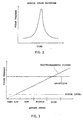
- the waveform of the pulse voltage is shown in Fig. 2.
- the changing and auxiliary magnets 40 and 50 converts the change of the gear rotation speed to the rate of change of magnetic state of the magnetic element 10 by the biasing magnet 30.
- the length of the changing and auxiliary magnets 40 and 50 are adjusted to the size of the object 60 to control the resolution so that the device according to the invention is useful for objects of different sizes.
- the pulse voltage can be below the noise level, whereas the amplitude of the pulse voltage by the invention keeps a predetermined level regardless of the speed of the object to be detected 60.
- the use of two magnets or changing and auxiliary magnets 40 and 50 assures detection of the object 60.
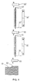
- Fig. 4 shows an application of the device of Fig. 1 to detect the object step by step.
- a new set of a magnetic element 10', a detection coil 20', a biasing magnet 30', and an auxiliary magnet 50 is added to the device of Fig. 1 to provide a double stage structure. More sets may be added to provide a multiple stage structure to detect the object step by step.
- the presence of the object 60 increases the magnetic field between the changing magnet 40 and the object 60 so that an external field of the same strength is produced from the changing magnet 40 to the auxiliary magnet 50.
- the external magnetic field from the auxiliary magnet 50 to the changing magnet 40 is changed, which in turn produces an external magnetic field of the same strength from auxiliary magnet 50 to the auxiliary magnet 50'.
- the magnetic field from the auxiliary magnet 50 to the auxiliary magnet 50' is slightly weaker than the magnetic field between the auxiliary and changing magnets 50 and 40.
- the first weak magnetic field 61 and the next stronger magnetic field 62 are detected between the changing and auxiliary magnets 40 and 50 and auxiliary magnets 50 and 50', respectively. In this way, the magnetic field is detected more accurately.
- Fig. 5 shows how to use the pulse signal generator of Fig. 1 to detect the teeth 71 of a rotary gear 70 which is made from a magnetic material and rotates in the direction of an arrow. Every time a tooth 71 passes the changing magnet 40, a pulse voltage is generated in the detection coil 20. The pulse voltage is processed to determine the rotary speed and angular position of the rotary gear 70.
- Fig. 6 shows another arrangement of the pulse signal generator of Fig. 1 to detect the teeth 71 of a gear 70 which is made from a magnetic material and rotates in the direction of an arrow. Every time a tooth 71 passes the changing magnet 40, a pulse voltage is generated in the detection coil 20. The pulse voltage is processed to determine the rotary speed and angular position of the rotary gear 70.
- the wire-type magnetic element 10 may be replaced by a thin film magnetic element.
- the detection coil 20 may also be replaced by a planar detection coil.
- the magnetic element may be a single layer magnetic element.
- the biasing permanent magnet may be replaced by an electromagnet.
- the detection coil may be replaced by a Hall element, MR element, or resonator circuit.
- the very low speed of a straight or rotary movement may be detected.
- the resulting pulse signal keeps a constant voltage and phase relationship so that it neither be overwhelmed by noise nor need a limiter.
- the use of auxiliary and changing magnets assures the production of a magnetic field between them. It is easy to provide a high resolution and possible to provide a powerless type and explosion proof device.
- the device is so compact that it can replace the conventional pickup or Hall effect sensor.
- the device can find more applications than the conventional electromagnetic pickup and Hall effect sensor.
- it can be used for the detection of r.p.m. and angle of an automobile engine, automobile ABS, motor, crank shaft, acceleration sensor, such as an air bag sensor, PC keyboard, plugging detection of HID lamps, vibration sensor, swing sensor, and door open/close sensor.
Landscapes
- Physics & Mathematics (AREA)
- Nonlinear Science (AREA)
- Transmission And Conversion Of Sensor Element Output (AREA)
- Measuring Magnetic Variables (AREA)
- Geophysics And Detection Of Objects (AREA)
- Measurement Of Length, Angles, Or The Like Using Electric Or Magnetic Means (AREA)
Description
- The present invention relates to a method and apparatus for generating a pulse signal.
- It is necessary to provide a pulse signal in response to the position or speed of a moving object in the field of automatic control or electric or electronic equipment. An electromagnetic pickup is an example of such pulse generators. This electromagnetic pickup comprises a magnetic body, a magnet, and an electrical coil. The magnetic flux varies with movement of the object to be detected to produce a voltage in the electrical coil by the electromagnetic induction. The voltage is used as a pulse signal.
- However, the electromagnetic pickup is not suitable in the following field. That is, if the object to be detected moves at very low speeds, the produced voltage is as low as the noise level. If an amplifier is used, the noise is also amplified so that it is necessary to use a filter for removing the noise prior to the amplification. Conversely, the object moves at high speeds, the resulting voltage exceeds the breakdown voltage of the amplifier, thus requiring a limiter. In the case of low speeds, an auxiliary ring is attached to the object to be detected to increase the diameter and thus the peripheral speed. However, this method increases the number of parts and the size of the device. In addition, the timing of rise or fall of the voltage varies with the moving speed of the object to be detected, requiring a complicated signal processor to provide an accurate timing detection. Moreover, the waveform of the voltage varies with the shape of the object to be detected.
- Another example is a Hall effect sensor used as a position sensor, angular sensor, or speed sensor. Japanese patent application Kokai No. 2-284082 discloses a Hall effect sensor. This Hall effect sensor comprises a Hall element and a magnet for changing the magnetic flux to the Hall element in response to movement of the object to be detected to provide an electrical signal from the Hall element. However, this type of sensor needs a power source to energize the Hall element. The output electrical signal is a sine wave and cannot produce a sharp pulse signal. If the object to be detected moves at low speeds, the rise of an output voltage is so low that the waveform is truncated. Like the above electromagnetic pickup, it is prone to an external magnetic field and noise and suffers from thermal drift, requiring a complicated processor to provide an accurate detection signal.
- Japanese patent application Kokai No. 54-161257 discloses still another type of pulse signal generator. This pulse signal generator comprises a magnetism sensitive element made from a ferromagnetic material so as to have relatively soft and hard portions of magnetic anisotropy, a first magnetic field source for magnetizing the magnetism sensitive element in a positive direction, a second magnetic field source for magnetizing the soft portion of the magnetism sensitive element in a negative direction, a detection coil provided in vicinity of the magnetism sensitive element, and a movable body for interrupting the magnetization of the magnetism sensitive element by the first magnetic field source so that a pulse voltage is produced in the detection coil by the movement of the movable body.
- This pulse signal generator is of the powerless type, provides a constant pulse voltage even if the movable object moves at very low speeds, and is resistant against an external magnetic field, thus solving some of the problems of the electromagnetic pickup and Hall effect sensor.
- However, this pulse signal generator has the following problems and stands far from practical use. First of all, it needs a movable body with a slit. This movable body cannot be made smaller than the magnet, such as first and second magnetic field sources, and the magnetism sensitive element. Since the slits are provided in the movable body in radial directions, it is necessary to provide a movable body of a large diameter in order to increase the resolution. In addition, the movable body, the magnet, and the magnetism sensitive element should be parallel to each other. The magnet is prone to an external magnetic field or metal to become unstable in operation. It cannot replace the electromagnetic pickup or Hall effect sensor depending on the spacial relationship with the object to be detected. For example, it cannot be disposed to detect directly the teeth of a gear.
- FR-A- 2 530 036 discloses a magnetic proximity sensor which employs a sensor winding arranged around a bistable metallic element such as a Wiegand wire, located along the central axis of a tubular magnet. The internal field component of the tubular magnet is opposed by a second field component generated by a radially magnetised disk magnet covering one end of the tubular magnet and a bar magnet centred at the other, open end of the tubular magnet. When an object of low magnetic resistance is brought into close proximity with the open end, the magnetic field of the tubular magnet is short circuited causing the opposing field component to predominate over the internal field component, thereby resetting the bistable magnetic element to an antiparallel condition.
- Accordingly, it is an object of the invention to provide a pulse signal generator which solves such problems as described above and are used for more applications than before.
- This object is achieved by the invention claimed in
claim 1. - Embodiments of the invention will now be described by way of example with reference to the accompanying drawings, in which:
- Fig. 1 is a schematic diagram of a pulse signal generator according to an embodiment of the invention;
- Fig. 2 is a graph showing the waveform of a pulse voltage generated by the pulse signal generator;
- Fig. 3 is a graph showing a comparison between the pulse voltage by the pulse signal generator and the pulse voltage by the conventional electromagnetic pickup;
- Fig. 4 is a schematic diagram showing a multiple stage structure of the pulse signal generator of Fig. 1;
- Fig. 5 is a schematic diagram showing an application of the pulse signal generator of Fig. 1; and
- Fig. 6 is a schematic diagram showing another application of the pulse signal generator of Fig. 1.
- Before embodiments are described, the "magnetic element capable of causing a large Barkhausen jump" (sometimes simply called "magnetic element") will be described. First of all, the structure and function of a wire-type composite magnetic element will be described. When a ferromagnetic body is drawn to form a wire, the wire has characteristic magnetic properties depending on the alloy composition. When the ferromagnetic wire is twisted, the peripheral and central regions have different magnetic properties because of different amounts of twist. Then, the wire is treated to provide a ferromagnetic wire which retains the magnetic properties. The magnetic direction of the peripheral region is changed by a weak magnetic field while the magnetic direction of the central region is changed by a magnetic field which is stronger than the magnetic field for the peripheral region. That is, the composite magnetic body has two kinds of magnetic regions; one which is magnetized easily and the other which is difficult to be magnetized. This composite magnetic wire is uniaxis anisotropic. The peripheral and central regions are called "soft" and "hard" layers, respectively, and the composite magnetic wire is called "wire-type composite magnetic element."
- The magnetic directions of the hard and soft layers are not determined initially. When an external field which is sufficiently strong to invert the magnetic direction of the hard layer is applied to the composite magnetic wire in the axial direction, both the soft and hard layers are magnetized in the same magnetic direction. Then, an external magnetic field which is sufficiently strong to magnetize only the soft layer is applied in the direction opposite to the previous direction. Consequently, the soft and hard layers are magnetized in opposite directions.
Since the element is uniaxial anisotropic, when the external field is removed, the magnetic direction of the soft layer remains stable under the influence of the hard layer. This external magnetic field is called "set magnetic field." Then, an external field which is opposite in direction is applied to increase the magnetic field. When the external magnetic field exceeds the critical strength, the magnetic direction of the soft layer is inverted abruptly. This magnetic field is called "critical magnetic field." The inversion phenomenon occurs instantly as the magnetic wall of the soft layer moves like avalanche. Consequently, the magnetic directions of the soft and hard layers are the same as the original state. This external magnetic field is stronger than the critical magnetic field and called "reset magnetic field." This avalanche phenomenon is called "large Barkhausen jump." The speed of the magnetic inversion depends on only the large Barkhausen jump and is irrelevant to the external magnetic field. - Beside the wire-type magnetic element, a variety of other magnetic elements which show the same properties may be used for the invention. A magnetic element which has no composite layers, such as hard and soft layers, may cause a large Barkhausen jump, too. For example, a thin film making technique such as disclosed in Japanese patent application Kokai No. 4-218905 is used to form a thin-film magnetic body. The magnetic elements may be of the thick films or plates. Thus, the "magnetic elements capable of causing large Barkhausen jump" include all the magnetic elements which show the above characteristics.
- An embodiment of the invention will now be described. In Fig. 1, a pulse signal generator comprises a wire-type
magnetic element 10, adetection coil 20 wound around the compositemagnetic element 1, a bar-like biasingpermanent magnet 30 disposed in the vicinity of themagnetic element 1 to produce a biasing magnetic field capable of magnetizing the soft and hard layers of themagnetic element 10 in opposite directions, and a changingmagnet 40 for changing the magnetic field in themagnetic element 10 when the object to be detected approaches the generator, and anauxiliary magnet 50 for forming a magnetic circuit between itself and the changingmagnet 40. - The operation of the pulse signal generator will be described. The body to be detected 10 is a tooth of a gear, for example. When the
gear tooth 60 is not in the vicinity of the changingmagnet 40, the biasing magnetic field of the biasingmagnet 30 is stronger than the magnetic field between the changingmagnet 40 and theauxiliary magnet 50 with respect to themagnetic element 10 and magnetizes only the soft layer of themagnetic element 10 in the direction opposite to the hard layer. When thegear tooth 10 is in the vicinity of the changingmagnet 40, the magnetic field between the changingmagnet 40 and theauxiliary magnet 50 is stronger than the biasing magnetic field of the biasingmagnet 30 with respect to themagnetic element 10 so that the magnetic field applied to themagnetic element 10 is inverted so as to align the magnetic directions of the hard and soft layers of themagnetic element 10. - The biasing
magnet 30 is provided to magnetize only the soft layer of themagnetic element 10 in the direction opposite to the direction of the hard layer. In order to assure stable magnetization of almost the entire length of themagnetic element 10, the biasingmagnet 30 is provided in parallel to themagnetic element 10 and has a length substantially the same as that of themagnetic element 10. The biasingmagnet 30 is a permanent magnet having N and S poles directed to the opposite poles of the changingmagnet 40 and theauxiliary magnet 50, respectively, as shown in Fig. 1. Since the external magnetic field of the biasingmagnet 30 has elliptical curves across the opposite ends of the magnet and runs substantially parallel to the axial direction of themagnetic element 10 so that themagnetic element 10 is magnetized in a predetermined direction substantially in the entire length. It is noted that the strength of magnetization by the biasingmagnet 30 is sufficient to magnetize only the soft layer of the biasingmagnet 30 in the direction opposite to that of the hard layer. - The changing
magnet 40 is a thin plate type permanent magnet. The thickness is reduced to reduce the manufacturing cost. Unlike the biasingmagnet 30, the changingmagnet 40 is magnetized in the thicknesswise direction to provide magnetic poles on the upper and lower sides. Consequently, the back magnetic field increases the internal magnetic field to increase the changing rate of the magnetic field. Themagnetic element 10 is flanked by the changing andauxiliary magnets auxiliary magnets magnetic element 10. The object to be detected 60 approaches the changingmagnet 40 from the side of the S pole which is opposite to the side facing theauxiliary magnet 50. - Like the changing
magnet 40, theauxiliary magnet 50 is a plate-like permanent magnet and is magnetized in the thicknesswise direction. Theauxiliary magnet 50 has a length substantially equal to that of the changingmagnet 40 and is provided in parallel to the changingmagnet 40 so that parallel magnetic fields are established between them. The use of theauxiliary magnet 50 makes it possible to increase changes of the magnetic fields between itself and the changingmagnet 40 and produce stable parallel magnetic fields between them. Theauxiliary magnet 50 may be replaced by a magnetic body such as an iron body. The magnetic body cannot increase changes of the magnetic fields but produces stable parallel magnetic fields. - In general, a magnet has two kinds of magnetic fields; i.e., internal and external magnetic fields. However, the changing and
auxiliary magnets magnet 40, more external magnetic fields are produced toward the object to be detected 60. In response to the production of external magnetic field in one pole, external magnetic fields of the same strength are produced at the opposite pole of the changingmagnet 40. These external magnetic fields appear as parallel magnetic fields between theauxiliary magnet 50 and the changingmagnet 40. An increase of the external magnetic field of the changingmagnet 40 increases the external magnetic field of theauxiliary magnet 50, which in turn increases the magnetic field between the changing andauxiliary magnets auxiliary magnet 50 has a strength slightly less than that of the changingmagnet 40. - When the
object 60 is not close to the changingmagnet 40, the magnetic fields between the changing andauxiliary magnets magnet 30 is dominant so that the soft layer of themagnetic element 10 is magnetized in the opposite direction to the hard layer,-establishing a set condition. When theobject 60 approaches the changingmagnet 40, the magnetic fields between the changing andauxiliary magnets magnet 30 so that the magnetic field of the same direction as the hard layer is applied. As a result, the soft layer is inverted in the same direction as the hard layer, causing a large Barkhausen jump. Since the magnetic field of the soft layer changes at very high speeds, a pulse voltage is produced in thedetection coil 20 by the electromagnetic induction. The waveform of the pulse voltage is shown in Fig. 2. The changing andauxiliary magnets magnetic element 10 by the biasingmagnet 30. The length of the changing andauxiliary magnets object 60 to control the resolution so that the device according to the invention is useful for objects of different sizes. - In this way, changes of the magnetic condition in the
magnetic element 10 are detected by thedetection coil 20 as pulse voltages by the electromagnetic induction. The presence or absence of a tooth of a gear causes a large Barkhausen jump regardless of the speed of the gear, thus producing a pulse signal without failure. Thus, even if theobject 60 moves at very slow speeds, it is possible to make detection. The pulse signal keeps a constant voltage and phase relationship. A comparison between the pulse voltage according to the invention and the pulse voltage by the conventional electromagnetic pickup is shown in Fig. 3. The amplitude of the pulse voltage by the conventional electromagnetic pickup varies with the speed of the object to be detected 60. When the object moves at very low speeds, the pulse voltage can be below the noise level, whereas the amplitude of the pulse voltage by the invention keeps a predetermined level regardless of the speed of the object to be detected 60. The use of two magnets or changing andauxiliary magnets object 60. - Fig. 4 shows an application of the device of Fig. 1 to detect the object step by step. A new set of a magnetic element 10', a detection coil 20', a biasing magnet 30', and an
auxiliary magnet 50 is added to the device of Fig. 1 to provide a double stage structure. More sets may be added to provide a multiple stage structure to detect the object step by step. - The presence of the
object 60 increases the magnetic field between the changingmagnet 40 and theobject 60 so that an external field of the same strength is produced from the changingmagnet 40 to theauxiliary magnet 50. In response, the external magnetic field from theauxiliary magnet 50 to the changingmagnet 40 is changed, which in turn produces an external magnetic field of the same strength fromauxiliary magnet 50 to the auxiliary magnet 50'. The magnetic field from theauxiliary magnet 50 to the auxiliary magnet 50' is slightly weaker than the magnetic field between the auxiliary and changingmagnets auxiliary magnets 50 and 50' by means of the detection coil 20' and the magnetic element10', it is possible to make a two-stage detection of the magnetic field. For example, where a step-like magnetic field is detected, the first weakmagnetic field 61 and the next strongermagnetic field 62 are detected between the changing andauxiliary magnets auxiliary magnets 50 and 50', respectively. In this way, the magnetic field is detected more accurately. - Fig. 5 shows how to use the pulse signal generator of Fig. 1 to detect the
teeth 71 of arotary gear 70 which is made from a magnetic material and rotates in the direction of an arrow. Every time atooth 71 passes the changingmagnet 40, a pulse voltage is generated in thedetection coil 20. The pulse voltage is processed to determine the rotary speed and angular position of therotary gear 70. - Fig. 6 shows another arrangement of the pulse signal generator of Fig. 1 to detect the
teeth 71 of agear 70 which is made from a magnetic material and rotates in the direction of an arrow. Every time atooth 71 passes the changingmagnet 40, a pulse voltage is generated in thedetection coil 20. The pulse voltage is processed to determine the rotary speed and angular position of therotary gear 70. - The wire-type
magnetic element 10 may be replaced by a thin film magnetic element. In this case, thedetection coil 20 may also be replaced by a planar detection coil. The magnetic element may be a single layer magnetic element. - The biasing permanent magnet may be replaced by an electromagnet. The detection coil may be replaced by a Hall element, MR element, or resonator circuit.
According to the invention, the very low speed of a straight or rotary movement may be detected. The resulting pulse signal keeps a constant voltage and phase relationship so that it neither be overwhelmed by noise nor need a limiter. The use of auxiliary and changing magnets assures the production of a magnetic field between them.
It is easy to provide a high resolution and possible to provide a powerless type and explosion proof device. The device is so compact that it can replace the conventional pickup or Hall effect sensor. - As described above, the device can find more applications than the conventional electromagnetic pickup and Hall effect sensor. For example, it can be used for the detection of r.p.m. and angle of an automobile engine, automobile ABS, motor, crank shaft, acceleration sensor, such as an air bag sensor, PC keyboard, plugging detection of HID lamps, vibration sensor, swing sensor, and door open/close sensor.
Claims (4)
- A pulse signal generator, comprising:a magnetic element (10) capable of causing a large Barkhausen jump;a detector (20) for detecting a change of magnetic field in said magnetic element;a magnetic field source (30) for magnetizing said magnetic element in a predetermined direction;a permanent magnet (40); andan auxiliary member (50) provided such that said magnetic element is flanked between said permanent magnet and said auxiliary member and is in an external magnetic field between said permanent magnet and said auxiliary member;characterised in that
said permanent magnet is a thin plate type magnet (40) magnetized in a thicknesswise direction thereof;
said auxiliary member is in the form of a thin plate magnet or a thin plate magnetic member; and
said external magnetic field varies with movement of said object with respect to said permanent magnet to produce said change of said magnetic field in said magnetic element which is detected by said detector to produce a pulse. - A pulse signal generator according to claim 1, which further comprises:a second auxiliary member provided to face said auxiliary member;a second magnetic element provided in a magnetic field produced between said auxiliary member and said second auxiliary member and capable of causing a large Barkhausen jump;a second magnetic field source for magnetizing said second magnetic element in a predetermined direction; anda second detector for detecting a change of magnetic field in said second magnetic element.
- A pulse signal generator according to claim 2, wherein said second auxiliary member, second magnetic element, second magnetic field source, and second detector are repeated in a subsequent stage to provide a multiple stage structure.
- A pulse signal generator according to one of claims 1-3, wherein said magnetic element is selected from the group consisting of a plate-like element, film-like element, and wire-like element.
Applications Claiming Priority (3)
| Application Number | Priority Date | Filing Date | Title |
|---|---|---|---|
| JP253805/97 | 1997-09-18 | ||
| JP25380597A JP3679907B2 (en) | 1997-09-18 | 1997-09-18 | Pulse signal generator |
| JP25380597 | 1997-09-18 |
Publications (3)
| Publication Number | Publication Date |
|---|---|
| EP0903856A2 EP0903856A2 (en) | 1999-03-24 |
| EP0903856A3 EP0903856A3 (en) | 1999-08-11 |
| EP0903856B1 true EP0903856B1 (en) | 2006-06-14 |
Family
ID=17256402
Family Applications (1)
| Application Number | Title | Priority Date | Filing Date |
|---|---|---|---|
| EP98650063A Expired - Lifetime EP0903856B1 (en) | 1997-09-18 | 1998-09-11 | Pulse signal generation method and apparatus |
Country Status (4)
| Country | Link |
|---|---|
| US (1) | US6259248B1 (en) |
| EP (1) | EP0903856B1 (en) |
| JP (1) | JP3679907B2 (en) |
| DE (1) | DE69834881T2 (en) |
Cited By (1)
| Publication number | Priority date | Publication date | Assignee | Title |
|---|---|---|---|---|
| US10234588B2 (en) | 2013-04-19 | 2019-03-19 | Trw Automotive Electronics & Components Gmbh | Magnetic proximity sensor |
Families Citing this family (10)
| Publication number | Priority date | Publication date | Assignee | Title |
|---|---|---|---|---|
| JP3615468B2 (en) * | 2000-07-06 | 2005-02-02 | ヒロセ電機株式会社 | Pulse signal generator |
| WO2002027339A1 (en) * | 2000-09-29 | 2002-04-04 | Sales & Promotions (Nz) Limited | An apparatus for testing an electrical device |
| JP5161505B2 (en) * | 2007-07-23 | 2013-03-13 | ヒロセ電機株式会社 | Magnetic sensor |
| JP2009147778A (en) * | 2007-12-17 | 2009-07-02 | Mabuchi Motor Co Ltd | Pulse signal generating apparatus, rotating machine, controller, and power window controller |
| JP2010119010A (en) * | 2008-11-14 | 2010-05-27 | Yokohama National Univ | Coil-wire separated electric pulse generating apparatus |
| JP5889144B2 (en) * | 2012-09-04 | 2016-03-22 | ヒロセ電機株式会社 | Rotation detector |
| WO2022153356A1 (en) * | 2021-01-12 | 2022-07-21 | 三菱電機株式会社 | Power generation element, magnetic sensor, and encoder |
| CN113718912B (en) * | 2021-08-17 | 2023-02-10 | 箭牌家居集团股份有限公司 | Switch device based on water induction and control method thereof |
| CN114858192B (en) * | 2022-03-17 | 2023-04-07 | 哈尔滨理工大学 | double-Hall magnetoelectric encoder based on double-wheel structure and angle resolving method thereof |
| CN120571906B (en) * | 2025-08-05 | 2025-10-10 | 山东众冶集团有限公司 | Cabin door cover edge positioning type stamping device |
Family Cites Families (5)
| Publication number | Priority date | Publication date | Assignee | Title |
|---|---|---|---|---|
| US4263525A (en) | 1978-12-26 | 1981-04-21 | Trw, Inc. | Signal generating means |
| DE3225499C2 (en) * | 1982-07-08 | 1984-05-24 | Doduco KG Dr. Eugen Dürrwächter, 7530 Pforzheim | Magnetic proximity sensor |
| JPH04218905A (en) * | 1990-03-23 | 1992-08-10 | Unitika Ltd | Thin film like magnetic material and its manufacture |
| DE4018148A1 (en) | 1990-06-06 | 1991-12-12 | Siemens Ag | MAGNETIC SENSITIVE SETUP WITH SEVERAL MAGNETIC SENSORS |
| US5338036A (en) * | 1993-06-09 | 1994-08-16 | Universal System Control, Inc. | Golf exercising aid device |
-
1997
- 1997-09-18 JP JP25380597A patent/JP3679907B2/en not_active Expired - Fee Related
-
1998
- 1998-09-10 US US09/150,619 patent/US6259248B1/en not_active Expired - Fee Related
- 1998-09-11 EP EP98650063A patent/EP0903856B1/en not_active Expired - Lifetime
- 1998-09-11 DE DE69834881T patent/DE69834881T2/en not_active Expired - Fee Related
Cited By (1)
| Publication number | Priority date | Publication date | Assignee | Title |
|---|---|---|---|---|
| US10234588B2 (en) | 2013-04-19 | 2019-03-19 | Trw Automotive Electronics & Components Gmbh | Magnetic proximity sensor |
Also Published As
| Publication number | Publication date |
|---|---|
| US6259248B1 (en) | 2001-07-10 |
| EP0903856A3 (en) | 1999-08-11 |
| JPH1197986A (en) | 1999-04-09 |
| DE69834881D1 (en) | 2006-07-27 |
| EP0903856A2 (en) | 1999-03-24 |
| DE69834881T2 (en) | 2006-12-21 |
| JP3679907B2 (en) | 2005-08-03 |
Similar Documents
| Publication | Publication Date | Title |
|---|---|---|
| US6160322A (en) | Pulse signal generation method and apparatus | |
| US5744950A (en) | Apparatus for detecting the speed of a rotating element including signal conditioning to provide a fifty percent duty cycle | |
| EP0916953B1 (en) | Pulse signal generator | |
| US6384595B1 (en) | Method of and apparatus for generating a pulse signal | |
| EP0903856B1 (en) | Pulse signal generation method and apparatus | |
| JPH11514747A (en) | Measuring device for detecting rotation angle without contact | |
| US3505595A (en) | Rotational speed sensor utilizing the phase shift caused by superposition of an a.c. signal in the sensor and a signal induced from the rotating body | |
| JPS63284416A (en) | Magnetic monitor monitoring parameter of angular motion of rotary member | |
| Kikuchi et al. | Consideration for a high resolution of magnetic rotary encoder | |
| JP3673412B2 (en) | Pulse signal generator | |
| US7268539B2 (en) | Pulse signal generator | |
| JP3617604B2 (en) | Pulse signal generator | |
| JP2007225536A (en) | Device for detecting rotary motion | |
| US6744153B2 (en) | Apparatus for and method of generating a pulse signal | |
| Powell et al. | Optimisation of magnetic speed sensors | |
| EP0391160B1 (en) | Variable reluctance sensor for detecting the rate of rotary or linear movement | |
| EP1770402A2 (en) | Pulse signal generator | |
| JPS648929B2 (en) | ||
| JPS58198760A (en) | Signal generator | |
| JPS5814058A (en) | Rotation signal generator | |
| JPH0684550U (en) | Rotation signal generator | |
| JP2011095198A (en) | Magnetic encoder | |
| JPS63257443A (en) | Magnetizing method of magnetization for frequency generator in brushless motor | |
| JPH0569447B2 (en) | ||
| JPH0449070B2 (en) |
Legal Events
| Date | Code | Title | Description |
|---|---|---|---|
| PUAI | Public reference made under article 153(3) epc to a published international application that has entered the european phase |
Free format text: ORIGINAL CODE: 0009012 |
|
| AK | Designated contracting states |
Kind code of ref document: A2 Designated state(s): DE FR GB IT SE |
|
| AX | Request for extension of the european patent |
Free format text: AL;LT;LV;MK;RO;SI |
|
| PUAL | Search report despatched |
Free format text: ORIGINAL CODE: 0009013 |
|
| AK | Designated contracting states |
Kind code of ref document: A3 Designated state(s): AT BE CH CY DE DK ES FI FR GB GR IE IT LI LU MC NL PT SE |
|
| AX | Request for extension of the european patent |
Free format text: AL;LT;LV;MK;RO;SI |
|
| 17P | Request for examination filed |
Effective date: 20000211 |
|
| AKX | Designation fees paid |
Free format text: DE FR GB IT SE |
|
| 17Q | First examination report despatched |
Effective date: 20031201 |
|
| GRAP | Despatch of communication of intention to grant a patent |
Free format text: ORIGINAL CODE: EPIDOSNIGR1 |
|
| GRAS | Grant fee paid |
Free format text: ORIGINAL CODE: EPIDOSNIGR3 |
|
| GRAA | (expected) grant |
Free format text: ORIGINAL CODE: 0009210 |
|
| AK | Designated contracting states |
Kind code of ref document: B1 Designated state(s): DE FR GB IT SE |
|
| REG | Reference to a national code |
Ref country code: GB Ref legal event code: FG4D |
|
| PGFP | Annual fee paid to national office [announced via postgrant information from national office to epo] |
Ref country code: FR Payment date: 20060705 Year of fee payment: 9 |
|
| REF | Corresponds to: |
Ref document number: 69834881 Country of ref document: DE Date of ref document: 20060727 Kind code of ref document: P |
|
| PGFP | Annual fee paid to national office [announced via postgrant information from national office to epo] |
Ref country code: GB Payment date: 20060906 Year of fee payment: 9 |
|
| PG25 | Lapsed in a contracting state [announced via postgrant information from national office to epo] |
Ref country code: SE Free format text: LAPSE BECAUSE OF FAILURE TO SUBMIT A TRANSLATION OF THE DESCRIPTION OR TO PAY THE FEE WITHIN THE PRESCRIBED TIME-LIMIT Effective date: 20060914 |
|
| PGFP | Annual fee paid to national office [announced via postgrant information from national office to epo] |
Ref country code: IT Payment date: 20060930 Year of fee payment: 9 |
|
| PGFP | Annual fee paid to national office [announced via postgrant information from national office to epo] |
Ref country code: DE Payment date: 20061027 Year of fee payment: 9 |
|
| ET | Fr: translation filed | ||
| PLBE | No opposition filed within time limit |
Free format text: ORIGINAL CODE: 0009261 |
|
| STAA | Information on the status of an ep patent application or granted ep patent |
Free format text: STATUS: NO OPPOSITION FILED WITHIN TIME LIMIT |
|
| 26N | No opposition filed |
Effective date: 20070315 |
|
| GBPC | Gb: european patent ceased through non-payment of renewal fee |
Effective date: 20070911 |
|
| PG25 | Lapsed in a contracting state [announced via postgrant information from national office to epo] |
Ref country code: DE Free format text: LAPSE BECAUSE OF NON-PAYMENT OF DUE FEES Effective date: 20080401 |
|
| REG | Reference to a national code |
Ref country code: FR Ref legal event code: ST Effective date: 20080531 |
|
| PG25 | Lapsed in a contracting state [announced via postgrant information from national office to epo] |
Ref country code: FR Free format text: LAPSE BECAUSE OF NON-PAYMENT OF DUE FEES Effective date: 20071001 |
|
| PG25 | Lapsed in a contracting state [announced via postgrant information from national office to epo] |
Ref country code: GB Free format text: LAPSE BECAUSE OF NON-PAYMENT OF DUE FEES Effective date: 20070911 |
|
| PG25 | Lapsed in a contracting state [announced via postgrant information from national office to epo] |
Ref country code: IT Free format text: LAPSE BECAUSE OF NON-PAYMENT OF DUE FEES Effective date: 20070911 |