EP0169670A2 - Proximity sensor - Google Patents
Proximity sensor Download PDFInfo
- Publication number
- EP0169670A2 EP0169670A2 EP85304476A EP85304476A EP0169670A2 EP 0169670 A2 EP0169670 A2 EP 0169670A2 EP 85304476 A EP85304476 A EP 85304476A EP 85304476 A EP85304476 A EP 85304476A EP 0169670 A2 EP0169670 A2 EP 0169670A2
- Authority
- EP
- European Patent Office
- Prior art keywords
- proximity sensor
- strip
- pole piece
- conductive member
- turn
- Prior art date
- Legal status (The legal status is an assumption and is not a legal conclusion. Google has not performed a legal analysis and makes no representation as to the accuracy of the status listed.)
- Granted
Links
- 230000004907 flux Effects 0.000 claims abstract description 8
- 230000008878 coupling Effects 0.000 claims description 5
- 238000010168 coupling process Methods 0.000 claims description 5
- 238000005859 coupling reaction Methods 0.000 claims description 5
- 238000000034 method Methods 0.000 claims 2
- CWYNVVGOOAEACU-UHFFFAOYSA-N Fe2+ Chemical compound [Fe+2] CWYNVVGOOAEACU-UHFFFAOYSA-N 0.000 abstract description 5
- 238000009413 insulation Methods 0.000 abstract description 5
- 239000004020 conductor Substances 0.000 abstract description 4
- 238000003475 lamination Methods 0.000 abstract description 4
- 230000001419 dependent effect Effects 0.000 abstract description 2
- 230000015556 catabolic process Effects 0.000 abstract 1
- XEEYBQQBJWHFJM-UHFFFAOYSA-N Iron Chemical compound [Fe] XEEYBQQBJWHFJM-UHFFFAOYSA-N 0.000 description 4
- 238000009434 installation Methods 0.000 description 4
- 230000005355 Hall effect Effects 0.000 description 2
- 229910052742 iron Inorganic materials 0.000 description 2
- 238000005259 measurement Methods 0.000 description 2
- RYGMFSIKBFXOCR-UHFFFAOYSA-N Copper Chemical compound [Cu] RYGMFSIKBFXOCR-UHFFFAOYSA-N 0.000 description 1
- 230000003466 anti-cipated effect Effects 0.000 description 1
- 229910052802 copper Inorganic materials 0.000 description 1
- 239000010949 copper Substances 0.000 description 1
- 239000011810 insulating material Substances 0.000 description 1
- 239000000523 sample Substances 0.000 description 1
- 229910001220 stainless steel Inorganic materials 0.000 description 1
- 239000010935 stainless steel Substances 0.000 description 1
- 238000004804 winding Methods 0.000 description 1
Images


Classifications
-
- G—PHYSICS
- G01—MEASURING; TESTING
- G01D—MEASURING NOT SPECIALLY ADAPTED FOR A SPECIFIC VARIABLE; ARRANGEMENTS FOR MEASURING TWO OR MORE VARIABLES NOT COVERED IN A SINGLE OTHER SUBCLASS; TARIFF METERING APPARATUS; MEASURING OR TESTING NOT OTHERWISE PROVIDED FOR
- G01D5/00—Mechanical means for transferring the output of a sensing member; Means for converting the output of a sensing member to another variable where the form or nature of the sensing member does not constrain the means for converting; Transducers not specially adapted for a specific variable
- G01D5/12—Mechanical means for transferring the output of a sensing member; Means for converting the output of a sensing member to another variable where the form or nature of the sensing member does not constrain the means for converting; Transducers not specially adapted for a specific variable using electric or magnetic means
- G01D5/14—Mechanical means for transferring the output of a sensing member; Means for converting the output of a sensing member to another variable where the form or nature of the sensing member does not constrain the means for converting; Transducers not specially adapted for a specific variable using electric or magnetic means influencing the magnitude of a current or voltage
- G01D5/20—Mechanical means for transferring the output of a sensing member; Means for converting the output of a sensing member to another variable where the form or nature of the sensing member does not constrain the means for converting; Transducers not specially adapted for a specific variable using electric or magnetic means influencing the magnitude of a current or voltage by varying inductance, e.g. by a movable armature
- G01D5/2006—Mechanical means for transferring the output of a sensing member; Means for converting the output of a sensing member to another variable where the form or nature of the sensing member does not constrain the means for converting; Transducers not specially adapted for a specific variable using electric or magnetic means influencing the magnitude of a current or voltage by varying inductance, e.g. by a movable armature by influencing the self-induction of one or more coils
- G01D5/2013—Mechanical means for transferring the output of a sensing member; Means for converting the output of a sensing member to another variable where the form or nature of the sensing member does not constrain the means for converting; Transducers not specially adapted for a specific variable using electric or magnetic means influencing the magnitude of a current or voltage by varying inductance, e.g. by a movable armature by influencing the self-induction of one or more coils by a movable ferromagnetic element, e.g. a core
Definitions
- This invention relates to proximity sensors and in particular to sensors for detecting the presence of ferrous objects.
- a proximity sensor may be used in co-operation with a toothed wheel on a shaft to give an output from which shaft rotational speed may be derived. In such an arrangement, the sensor is placed close to the wheel such that the passing of a tooth may be detected.
- Another use is in torque measurement wherein a proximity sensor is used to measure the gap between interleaved teeth of a wheel and torque tube. Such an arrangement is described in published UK Patent Application GB 2 082 859 A.
- a proximity sensor comprises a coil disposed around a magnetic pole such that a passing ferrous object includes an output voltage in the coil.
- a coil having many turns is required, and coils having at least 200 turns have been used.
- the requirement for a large number of turns tends to lead to a bulky sensor, which may be inconveniently large compared with the installation space available.
- a plurality of coils may be wound about the same pole, which further increases size.
- Sensors are often required to be sited in areas of limited space and of high temperature, such as in a gas turbine engine. Since a multi-turn coil is employed. the performance of the interwinding insulation must be adequate over the expected temperature range, else the coil will short and the sensor fail. With the trend to the operation of gas turbines at increasingly high temperatures, it is anticipated that the temperature to which a gas turbine sensor is subjected in use may exceed that at which the performance of the insulation can be guaranteed. Thus conventional sensors may prove unreliable in future engines.
- a proximity sensor includes an elongate electrically conductive member arranged to form a closed electrical circuit
- the sensor may operate in high temperature conditions by locating the remote region of the conductive element in an area of lower temperature or where heat may be sunk.
- various low temperature detectors may be used at the remote region.
- a coupling transformer which may have a single coil or alternatively multiple coils to provide a multi-output sensor.
- a magnetically energized second pole may be coupled to the circuit at the remote region.
- the field surrounding such a field will fluctuate in sympathy with current variation in the circuit.
- These field fluctions may be detected by, for example a Hall effect detector, a magneto-resistor or by a magneto-optical link.
- Magnetic energization may be provided by a permanent magnet contactng or adjusting the pole piece.
- a single turn circuit is made by forming a slot in a conductive strip.
- the pole piece may then protrude to one side of the strip through an end of the slot and from a magnet on the other side of the strip.
- the conductive member may be formed around the pole piece to provide multi-turn coupling, for example by folding a strip member bellows-like over the pole piece such that it protrudes through slots therein.
- a single turn electrical circuit is formed by a slot 10 in a conductive strip 11.
- the strip 11 carries a magnet 12 contacting a pole piece 14 protruding through the strip 11 at one end of slot 10.
- laminations 15 which magnetically couple the electrical circuit and a multi-turn coil 16 on a former 17 attached to the strip 11.
- the coil 16 is terminated at an output pair 18.
- a ferrous object passing in the vicinity of pole piece 14 modifies the flux pattern at the pole face.
- the resultant flux changes, being tightly coupled to the electrical conductor 11 induce a low voltage high current emf into the conductor 11, which forms the primary turn of a current transfomer.
- the secondary of the current transformer is formed by the close coupled coil 17, which has multiple turns, dependent upon the output voltage required at output pair 18.
- a sensor 30 ( Figure 3) is positioned (by means not shown) adjacent a toothed wheel 31, the rotational speed of which is to be measured.
- the passage of teeth. such as tooth 32, past pole piece 14 gives rise to an output signal directly related to passing frequency, as hereinbefore described.
- the slotted conductive strip 11 ( Figure 1) which constitutes the primary turn was formed in copper.
- a high temperature magnet with a soft iron pole piece was used.
- the secondary was formed of high temperature winding wire (insulation reliable up to 200°C) with transformer iron laminations.
- the conductive strip 11 may be bare of insulating material, the high temperature performance is extended beyond the point at which normal insulation breaks down.
- the present example maintains a response at high temperatures provided the site of the secondary coil 16 is maintained at 200°C or below. This was achieved by elongating the strip 11 such that the coil 16 was at a cooler location.
- a coil is not required on the pole piece at the sensing region. which may therefore be much reduced in size compared with a conventional sensor.
- the present invention shows great advantage in installation.
- the dimensions are such that unlike a prior art sensor the passage of the teeth may be sensed from the side, even towards the tooth root (as indicated in phantom 33 of Figure 3), which can alleviate measurement problems caused by narrow teeth tips. and is more convenient in some installations.
- a condutive member 40 ( Figure 4) is formed in the region of a pole piece 41 and pick off coil 42, to provide multi-turn coupling of the closed electrical circuit.
- the multiple turns are formed (as may be more clearly seen in Figure 5. in which common reference numerals have been used) by folding the member bellows like in the sensing region 50 and remote region 51.
- the strip carries slots , such a slots 52 and 53 in the sensing and remote regions respectively to receive the pole piece 41 and laminations 43. It will be appreciated that as the strip is folded down over for example pole piece 41 a stack of three air spaced half turns is formed around pole face portion 54.
- Magnetic energisation is provided by permanent magnet 44.
- This latter embodiment of the invention presents a number of advantages.
- magnetic coupling is promoted by virtue of the multiple turns.
- the arrangement is readily adapted to be mounted in a cylindrical case, as is preferred for sensors to be installed in gas turbine engines.
- a member 60 ( Figure 6a) may be readily mounted in a closed cylindrical stainless steel case 61, which constitutes a conventional engine proximity probe case.
- conductive member 40 may be straightforwardly fabricated by stamping, from a single sheet, folding and joining.
- a yet further embodient of the present invention employs a secondary pole piece 70 at a remote region 71.
- the flux pattern surrounding pole piece protrusion 72 will fluctuate in sympathy therewith. This fluctuation is detected by Hall effect detector 73 to provide a sensor output at terminations 74.
Landscapes
- Physics & Mathematics (AREA)
- General Physics & Mathematics (AREA)
- Switches That Are Operated By Magnetic Or Electric Fields (AREA)
- Measurement Of Length, Angles, Or The Like Using Electric Or Magnetic Means (AREA)
Abstract
Description
- This invention relates to proximity sensors and in particular to sensors for detecting the presence of ferrous objects. A proximity sensor may be used in co-operation with a toothed wheel on a shaft to give an output from which shaft rotational speed may be derived. In such an arrangement, the sensor is placed close to the wheel such that the passing of a tooth may be detected. Another use is in torque measurement wherein a proximity sensor is used to measure the gap between interleaved teeth of a wheel and torque tube. Such an arrangement is described in published UK Patent Application GB 2 082 859 A.
- In the prior art, a proximity sensor comprises a coil disposed around a magnetic pole such that a passing ferrous object includes an output voltage in the coil. In order to provide an output of reasonable level, a coil having many turns is required, and coils having at least 200 turns have been used. The requirement for a large number of turns tends to lead to a bulky sensor, which may be inconveniently large compared with the installation space available. For a multiple output sensor a plurality of coils may be wound about the same pole, which further increases size.
- Sensors are often required to be sited in areas of limited space and of high temperature, such as in a gas turbine engine. Since a multi-turn coil is employed. the performance of the interwinding insulation must be adequate over the expected temperature range, else the coil will short and the sensor fail. With the trend to the operation of gas turbines at increasingly high temperatures, it is anticipated that the temperature to which a gas turbine sensor is subjected in use may exceed that at which the performance of the insulation can be guaranteed. Thus conventional sensors may prove unreliable in future engines.
- According to the present invention a proximity sensor includes an elongate electrically conductive member arranged to form a closed electrical circuit,
- a magnetically energized pole piece situated at a sensing region of the conductive member such that the member is magnetically coupled to the pole piece surrounding flux pattern,
- and means situated at a remote region of the conductive member for detecting current in the circuit.
- In use, movement of a ferrous object in the vicinity of the pole piece will influence the operating flux and induce an electro-motive force (emf) into the conductive member. which will drive a current therethrough. Remote sensing of the current will thus provide an indication of movement proximate the pole piece.
- The sensor may operate in high temperature conditions by locating the remote region of the conductive element in an area of lower temperature or where heat may be sunk. Thus various low temperature detectors may be used at the remote region. for example a coupling transformer. which may have a single coil or alternatively multiple coils to provide a multi-output sensor.
- Alternatively a magnetically energized second pole may be coupled to the circuit at the remote region. The field surrounding such a field will fluctuate in sympathy with current variation in the circuit. These field fluctions may be detected by, for example a Hall effect detector, a magneto-resistor or by a magneto-optical link.
- Magnetic energization may be provided by a permanent magnet contactng or adjusting the pole piece.
- In one form of the present invention a single turn circuit is made by forming a slot in a conductive strip. The pole piece may then protrude to one side of the strip through an end of the slot and from a magnet on the other side of the strip.
- In an alterative form of the present invention the conductive member may be formed around the pole piece to provide multi-turn coupling, for example by folding a strip member bellows-like over the pole piece such that it protrudes through slots therein.
- In order that features and advantages of the present invention may be appreciated an embodiment will now be described by way of example only and with reference to the accompanying diagrammatic drawings of which:-
- Figures 1 and 2 represent a proximity sensor in accordance with the present invention, and
- Figure 3 shows a typical installation of the sensor of Figures 1 and 2.
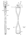
- Figure 4 shows an alternative embodiment of a proximity sensor,
- Figure 5, represents an assembly view of the sensor of Figure 4,
- Figure 6 represents a cased proximity sensor, and
- Figure 7 represents a further alternative embodiment.
- In a proximity sensor (Figures 1 and 2) a single turn electrical circuit is formed by a
slot 10 in aconductive strip 11. Thestrip 11 carries amagnet 12 contacting apole piece 14 protruding through thestrip 11 at one end ofslot 10. At the other end of theslot 10pass laminations 15 which magnetically couple the electrical circuit and amulti-turn coil 16 on a former 17 attached to thestrip 11. Thecoil 16 is terminated at anoutput pair 18. - A ferrous object passing in the vicinity of
pole piece 14 modifies the flux pattern at the pole face. The resultant flux changes, being tightly coupled to theelectrical conductor 11 induce a low voltage high current emf into theconductor 11, which forms the primary turn of a current transfomer. The secondary of the current transformer is formed by the close coupledcoil 17, which has multiple turns, dependent upon the output voltage required atoutput pair 18. - In use, a sensor 30 (Figure 3) is positioned (by means not shown) adjacent a
toothed wheel 31, the rotational speed of which is to be measured. The passage of teeth. such astooth 32,past pole piece 14 gives rise to an output signal directly related to passing frequency, as hereinbefore described. - In an example of the present invention constructed for use in a high temperature environment, the slotted conductive strip 11 (Figure 1) which constitutes the primary turn was formed in copper. A high temperature magnet with a soft iron pole piece was used. The secondary was formed of high temperature winding wire (insulation reliable up to 200°C) with transformer iron laminations. As previously described since the
conductive strip 11 may be bare of insulating material, the high temperature performance is extended beyond the point at which normal insulation breaks down. The present example maintains a response at high temperatures provided the site of thesecondary coil 16 is maintained at 200°C or below. This was achieved by elongating thestrip 11 such that thecoil 16 was at a cooler location. - It will be appreciated that in the present invention a coil is not required on the pole piece at the sensing region. which may therefore be much reduced in size compared with a conventional sensor. Thus the present invention shows great advantage in installation. The dimensions are such that unlike a prior art sensor the passage of the teeth may be sensed from the side, even towards the tooth root (as indicated in
phantom 33 of Figure 3), which can alleviate measurement problems caused by narrow teeth tips. and is more convenient in some installations. - In an alternative embodiment of the present invention a condutive member 40 (Figure 4) is formed in the region of a
pole piece 41 and pick offcoil 42, to provide multi-turn coupling of the closed electrical circuit. The multiple turns are formed (as may be more clearly seen in Figure 5. in which common reference numerals have been used) by folding the member bellows like in thesensing region 50 andremote region 51. The strip carries slots , such aslots pole piece 41 andlaminations 43. It will be appreciated that as the strip is folded down over for example pole piece 41 a stack of three air spaced half turns is formed aroundpole face portion 54. - Magnetic energisation is provided by
permanent magnet 44. - This latter embodiment of the invention presents a number of advantages. In particular magnetic coupling is promoted by virtue of the multiple turns. Further, the arrangement is readily adapted to be mounted in a cylindrical case, as is preferred for sensors to be installed in gas turbine engines. For example a member 60 (Figure 6a) may be readily mounted in a closed cylindrical
stainless steel case 61, which constitutes a conventional engine proximity probe case. Furthermore.conductive member 40 may be straightforwardly fabricated by stamping, from a single sheet, folding and joining. - As an alternative to coil pick off, a yet further embodient of the present invention (Figure 7, bearing common reference numerals with Figure 4) employs a
secondary pole piece 70 at aremote region 71. When current flows inconductive member 40 by virtue of induced emf as hereinbefore described, the flux pattern surroundingpole piece protrusion 72 will fluctuate in sympathy therewith. This fluctuation is detected byHall effect detector 73 to provide a sensor output atterminations 74.
Claims (15)
Applications Claiming Priority (2)
| Application Number | Priority Date | Filing Date | Title |
|---|---|---|---|
| GB8416109 | 1984-06-23 | ||
| GB848416109A GB8416109D0 (en) | 1984-06-23 | 1984-06-23 | Proximity sensor |
Publications (3)
| Publication Number | Publication Date |
|---|---|
| EP0169670A2 true EP0169670A2 (en) | 1986-01-29 |
| EP0169670A3 EP0169670A3 (en) | 1988-01-20 |
| EP0169670B1 EP0169670B1 (en) | 1993-03-17 |
Family
ID=10562930
Family Applications (1)
| Application Number | Title | Priority Date | Filing Date |
|---|---|---|---|
| EP85304476A Expired - Lifetime EP0169670B1 (en) | 1984-06-23 | 1985-06-24 | Proximity sensor |
Country Status (6)
| Country | Link |
|---|---|
| US (1) | US4739260A (en) |
| EP (1) | EP0169670B1 (en) |
| JP (1) | JPH07117362B2 (en) |
| CA (1) | CA1255772A (en) |
| DE (1) | DE3587185T2 (en) |
| GB (1) | GB8416109D0 (en) |
Cited By (10)
| Publication number | Priority date | Publication date | Assignee | Title |
|---|---|---|---|---|
| GB2179453B (en) * | 1985-08-21 | 1989-08-02 | Gen Electric Plc | An instrument for detecting a changing magnetic field |
| EP0455613A3 (en) * | 1990-05-03 | 1994-02-16 | Alessandro Dreoni | |
| US7148679B2 (en) | 2002-04-16 | 2006-12-12 | Weston Aerospace Limited | Transformer probe |
| EP1522825A3 (en) * | 2003-10-08 | 2007-05-02 | Weston Aerospace Limited | Probe with transformator coupling |
| EP2073020A1 (en) | 2007-12-21 | 2009-06-24 | Weston Aerospace Limited | Method and apparatus for monitoring the rotational speed of the shaft of a gas turbine |
| EP2073021A1 (en) | 2007-12-21 | 2009-06-24 | Weston Aerospace Limited | Method and apparatus for monitoring the rotational speed of a shaft |
| EP2230487A2 (en) | 2009-03-18 | 2010-09-22 | Weston Aerospace Limited | Protective system for a multiple channel transformer probe |
| US7840370B2 (en) | 2007-12-21 | 2010-11-23 | Weston Aerospace Limited | Method and apparatus for monitoring the rotational speed of shaft |
| US8229646B2 (en) | 2007-12-21 | 2012-07-24 | Weston Aerospace Limited | Method and apparatus for monitoring gas turbine blades |
| US10976221B2 (en) | 2018-01-09 | 2021-04-13 | Weston Aerospace Limited | Magnetic gas turbine sensor |
Families Citing this family (5)
| Publication number | Priority date | Publication date | Assignee | Title |
|---|---|---|---|---|
| US6346807B1 (en) * | 1999-10-22 | 2002-02-12 | Bently Nevada Corporation | Digital eddy current proximity system: apparatus and method |
| GB0006144D0 (en) * | 2000-03-14 | 2000-05-03 | Isis Innovation | Position and electromagnetic field sensor |
| KR100505929B1 (en) * | 2003-03-31 | 2005-08-04 | 삼성광주전자 주식회사 | A compressor and A method for connecting pipeline of compressor |
| GB2461494B (en) * | 2008-01-29 | 2012-03-07 | Weston Aerospace Ltd | Speed sensor |
| GB2462070B (en) * | 2008-07-18 | 2010-06-30 | Weston Aerospace Ltd | Contactless connector for use in a gas turbine |
Family Cites Families (9)
| Publication number | Priority date | Publication date | Assignee | Title |
|---|---|---|---|---|
| US2532100A (en) * | 1947-05-29 | 1950-11-28 | Indiana Steel Products Co | Electromagnetic transducer head |
| US2897462A (en) * | 1956-06-01 | 1959-07-28 | Hughes Aircraft Co | Variable reluctance electromagnetic device |
| US3230407A (en) * | 1962-08-01 | 1966-01-18 | Anelex Corp | Electromagnetic transducers |
| JPS48103080U (en) * | 1972-03-02 | 1973-12-03 | ||
| US3876927A (en) * | 1973-12-20 | 1975-04-08 | Electro Corp America | Magnetic sensor with shorted turn |
| FR2460484A1 (en) * | 1979-06-29 | 1981-01-23 | Thomson Csf | MAGNETOELECTRIC DISPLACEMENT SENSOR OF A MOVING PIECE, AND DETECTION SYSTEM PROVIDED WITH SUCH A SENSOR |
| US4444063A (en) * | 1980-08-27 | 1984-04-24 | Sangamo Weston Limited | Torque measuring systems |
| GB2082859B (en) * | 1980-08-27 | 1985-02-27 | Sangamo Weston | Torque measuring systems |
| JPS6017701Y2 (en) * | 1981-12-28 | 1985-05-30 | 住友重機械工業株式会社 | mold level meter |
-
1984
- 1984-06-23 GB GB848416109A patent/GB8416109D0/en active Pending
-
1985
- 1985-06-21 US US06/747,205 patent/US4739260A/en not_active Expired - Lifetime
- 1985-06-24 JP JP60137642A patent/JPH07117362B2/en not_active Expired - Lifetime
- 1985-06-24 EP EP85304476A patent/EP0169670B1/en not_active Expired - Lifetime
- 1985-06-24 CA CA000484958A patent/CA1255772A/en not_active Expired
- 1985-06-24 DE DE8585304476T patent/DE3587185T2/en not_active Expired - Lifetime
Cited By (15)
| Publication number | Priority date | Publication date | Assignee | Title |
|---|---|---|---|---|
| GB2179453B (en) * | 1985-08-21 | 1989-08-02 | Gen Electric Plc | An instrument for detecting a changing magnetic field |
| EP0455613A3 (en) * | 1990-05-03 | 1994-02-16 | Alessandro Dreoni | |
| US7148679B2 (en) | 2002-04-16 | 2006-12-12 | Weston Aerospace Limited | Transformer probe |
| EP1522825A3 (en) * | 2003-10-08 | 2007-05-02 | Weston Aerospace Limited | Probe with transformator coupling |
| US7856337B2 (en) | 2007-12-21 | 2010-12-21 | Weston Aerospace Limited | Method and apparatus for monitoring the rotational speed of the shaft of a gas turbine |
| EP2073021A1 (en) | 2007-12-21 | 2009-06-24 | Weston Aerospace Limited | Method and apparatus for monitoring the rotational speed of a shaft |
| US7840370B2 (en) | 2007-12-21 | 2010-11-23 | Weston Aerospace Limited | Method and apparatus for monitoring the rotational speed of shaft |
| EP2073020A1 (en) | 2007-12-21 | 2009-06-24 | Weston Aerospace Limited | Method and apparatus for monitoring the rotational speed of the shaft of a gas turbine |
| US8229646B2 (en) | 2007-12-21 | 2012-07-24 | Weston Aerospace Limited | Method and apparatus for monitoring gas turbine blades |
| EP2230487A2 (en) | 2009-03-18 | 2010-09-22 | Weston Aerospace Limited | Protective system for a multiple channel transformer probe |
| GB2470343A (en) * | 2009-03-18 | 2010-11-24 | Weston Aerospace Ltd | Open circuit protection system for a multiple channel transformer probe |
| GB2470343B (en) * | 2009-03-18 | 2011-04-27 | Weston Aerospace Ltd | Protective system for a multiple channel transformer probe |
| US8253410B2 (en) | 2009-03-18 | 2012-08-28 | Weston Aerospace Limited | Protective system for a multiple channel transformer probe |
| EP2230487A3 (en) * | 2009-03-18 | 2015-11-25 | Weston Aerospace Limited | Protective system for a multiple channel transformer probe |
| US10976221B2 (en) | 2018-01-09 | 2021-04-13 | Weston Aerospace Limited | Magnetic gas turbine sensor |
Also Published As
| Publication number | Publication date |
|---|---|
| EP0169670A3 (en) | 1988-01-20 |
| DE3587185T2 (en) | 1993-07-15 |
| DE3587185D1 (en) | 1993-04-22 |
| JPH07117362B2 (en) | 1995-12-18 |
| CA1255772A (en) | 1989-06-13 |
| US4739260A (en) | 1988-04-19 |
| GB8416109D0 (en) | 1984-07-25 |
| JPS61129504A (en) | 1986-06-17 |
| EP0169670B1 (en) | 1993-03-17 |
Similar Documents
| Publication | Publication Date | Title |
|---|---|---|
| US4739260A (en) | Proximity sensor with remotely coupled output | |
| US3439256A (en) | Inductive angular position transmitter | |
| JPS6330223Y2 (en) | ||
| US7170284B2 (en) | Blade detection sensor having an active cooling system | |
| CA2593553C (en) | Aerospace movement probe | |
| US6927567B1 (en) | Passive eddy current blade detection sensor | |
| US6288535B1 (en) | Hall effect, shaft angular position sensor with asymmetrical rotor | |
| US7148679B2 (en) | Transformer probe | |
| JP3323273B2 (en) | Measuring device for defining the rotation angle | |
| KR100952226B1 (en) | Combined flux, surge and temperature sensors for monitoring the status of generators and motors during operation | |
| RU2001128250A (en) | The method of measuring the motion parameters of the ends of the blades of the rotor of a turbomachine and a device for its implementation | |
| CA1200401A (en) | Speed sensor for an electromagnetic machine | |
| EP0917157B1 (en) | Insulator | |
| US4382230A (en) | Movement sensor with plate forming single turn coils | |
| JPS59105505A (en) | Eddy current type position detector and manufacture thereof | |
| US20050083040A1 (en) | Probe | |
| US1961782A (en) | Alternating current dynamo-electric machine | |
| EP2230487A2 (en) | Protective system for a multiple channel transformer probe | |
| JPS59501838A (en) | Inductive length and angle measuring device | |
| JPS6226074B2 (en) | ||
| KR0178165B1 (en) | Temperature sensor | |
| RU68201U1 (en) | TURBOGENERATOR STATOR CORE TEMPERATURE CONTROL DEVICE | |
| US20250048554A1 (en) | Flexible printed circuit rogowski coil | |
| US4814700A (en) | Field current measurement device | |
| JP2000180108A (en) | Position detector |
Legal Events
| Date | Code | Title | Description |
|---|---|---|---|
| PUAI | Public reference made under article 153(3) epc to a published international application that has entered the european phase |
Free format text: ORIGINAL CODE: 0009012 |
|
| AK | Designated contracting states |
Designated state(s): DE FR GB IT |
|
| PUAL | Search report despatched |
Free format text: ORIGINAL CODE: 0009013 |
|
| AK | Designated contracting states |
Kind code of ref document: A3 Designated state(s): DE FR GB IT |
|
| 17P | Request for examination filed |
Effective date: 19880620 |
|
| RAP1 | Party data changed (applicant data changed or rights of an application transferred) |
Owner name: SCHLUMBERGER INDUSTRIES LIMITED |
|
| 17Q | First examination report despatched |
Effective date: 19891011 |
|
| GRAA | (expected) grant |
Free format text: ORIGINAL CODE: 0009210 |
|
| ITF | It: translation for a ep patent filed | ||
| AK | Designated contracting states |
Kind code of ref document: B1 Designated state(s): DE FR GB IT |
|
| REF | Corresponds to: |
Ref document number: 3587185 Country of ref document: DE Date of ref document: 19930422 |
|
| ET | Fr: translation filed | ||
| PLBE | No opposition filed within time limit |
Free format text: ORIGINAL CODE: 0009261 |
|
| STAA | Information on the status of an ep patent application or granted ep patent |
Free format text: STATUS: NO OPPOSITION FILED WITHIN TIME LIMIT |
|
| 26N | No opposition filed | ||
| REG | Reference to a national code |
Ref country code: GB Ref legal event code: 732E |
|
| REG | Reference to a national code |
Ref country code: GB Ref legal event code: 732E |
|
| REG | Reference to a national code |
Ref country code: FR Ref legal event code: TP |
|
| REG | Reference to a national code |
Ref country code: GB Ref legal event code: IF02 |
|
| PGFP | Annual fee paid to national office [announced via postgrant information from national office to epo] |
Ref country code: FR Payment date: 20040608 Year of fee payment: 20 |
|
| PGFP | Annual fee paid to national office [announced via postgrant information from national office to epo] |
Ref country code: GB Payment date: 20040623 Year of fee payment: 20 |
|
| PGFP | Annual fee paid to national office [announced via postgrant information from national office to epo] |
Ref country code: DE Payment date: 20040701 Year of fee payment: 20 |
|
| PG25 | Lapsed in a contracting state [announced via postgrant information from national office to epo] |
Ref country code: GB Free format text: LAPSE BECAUSE OF EXPIRATION OF PROTECTION Effective date: 20050623 |
|
| REG | Reference to a national code |
Ref country code: GB Ref legal event code: PE20 |
|
| APAH | Appeal reference modified |
Free format text: ORIGINAL CODE: EPIDOSCREFNO |