EP3517974A1 - Automatic analysis device - Google Patents
Automatic analysis device Download PDFInfo
- Publication number
- EP3517974A1 EP3517974A1 EP17852710.7A EP17852710A EP3517974A1 EP 3517974 A1 EP3517974 A1 EP 3517974A1 EP 17852710 A EP17852710 A EP 17852710A EP 3517974 A1 EP3517974 A1 EP 3517974A1
- Authority
- EP
- European Patent Office
- Prior art keywords
- sample
- stop position
- arm
- nozzle
- nozzles
- Prior art date
- Legal status (The legal status is an assumption and is not a legal conclusion. Google has not performed a legal analysis and makes no representation as to the accuracy of the status listed.)
- Granted
Links
- 238000004458 analytical method Methods 0.000 title description 11
- 238000006243 chemical reaction Methods 0.000 claims abstract description 88
- 238000001514 detection method Methods 0.000 claims abstract description 59
- 230000007246 mechanism Effects 0.000 claims description 38
- 239000003153 chemical reaction reagent Substances 0.000 claims description 24
- 238000007599 discharging Methods 0.000 claims description 22
- 239000007788 liquid Substances 0.000 claims description 12
- 238000005452 bending Methods 0.000 abstract description 7
- 239000000523 sample Substances 0.000 description 168
- 238000000034 method Methods 0.000 description 24
- 238000010586 diagram Methods 0.000 description 20
- 238000005259 measurement Methods 0.000 description 16
- 238000004140 cleaning Methods 0.000 description 9
- 230000001174 ascending effect Effects 0.000 description 7
- 230000007723 transport mechanism Effects 0.000 description 6
- 239000000463 material Substances 0.000 description 4
- 239000008280 blood Substances 0.000 description 3
- 210000004369 blood Anatomy 0.000 description 3
- 238000003756 stirring Methods 0.000 description 3
- 210000002700 urine Anatomy 0.000 description 3
- 239000012472 biological sample Substances 0.000 description 2
- 239000004020 conductor Substances 0.000 description 2
- 230000006870 function Effects 0.000 description 2
- 238000007689 inspection Methods 0.000 description 2
- 238000000691 measurement method Methods 0.000 description 2
- 238000000926 separation method Methods 0.000 description 2
- 238000004737 colorimetric analysis Methods 0.000 description 1
- 238000013016 damping Methods 0.000 description 1
- 238000003745 diagnosis Methods 0.000 description 1
- 238000006073 displacement reaction Methods 0.000 description 1
- 230000000694 effects Effects 0.000 description 1
- 239000011521 glass Substances 0.000 description 1
- 238000003018 immunoassay Methods 0.000 description 1
- 239000003550 marker Substances 0.000 description 1
- 239000002184 metal Substances 0.000 description 1
- 238000004451 qualitative analysis Methods 0.000 description 1
- 238000004445 quantitative analysis Methods 0.000 description 1
- 230000004044 response Effects 0.000 description 1
- 230000001360 synchronised effect Effects 0.000 description 1
- 238000002834 transmittance Methods 0.000 description 1
- XLYOFNOQVPJJNP-UHFFFAOYSA-N water Substances O XLYOFNOQVPJJNP-UHFFFAOYSA-N 0.000 description 1
Images


Classifications
-
- G—PHYSICS
- G01—MEASURING; TESTING
- G01N—INVESTIGATING OR ANALYSING MATERIALS BY DETERMINING THEIR CHEMICAL OR PHYSICAL PROPERTIES
- G01N35/00—Automatic analysis not limited to methods or materials provided for in any single one of groups G01N1/00 - G01N33/00; Handling materials therefor
- G01N35/00584—Control arrangements for automatic analysers
-
- G—PHYSICS
- G01—MEASURING; TESTING
- G01N—INVESTIGATING OR ANALYSING MATERIALS BY DETERMINING THEIR CHEMICAL OR PHYSICAL PROPERTIES
- G01N35/00—Automatic analysis not limited to methods or materials provided for in any single one of groups G01N1/00 - G01N33/00; Handling materials therefor
- G01N35/10—Devices for transferring samples or any liquids to, in, or from, the analysis apparatus, e.g. suction devices, injection devices
- G01N35/1009—Characterised by arrangements for controlling the aspiration or dispense of liquids
- G01N35/1011—Control of the position or alignment of the transfer device
-
- G—PHYSICS
- G01—MEASURING; TESTING
- G01N—INVESTIGATING OR ANALYSING MATERIALS BY DETERMINING THEIR CHEMICAL OR PHYSICAL PROPERTIES
- G01N35/00—Automatic analysis not limited to methods or materials provided for in any single one of groups G01N1/00 - G01N33/00; Handling materials therefor
- G01N35/00584—Control arrangements for automatic analysers
- G01N35/00594—Quality control, including calibration or testing of components of the analyser
- G01N35/00693—Calibration
-
- G—PHYSICS
- G01—MEASURING; TESTING
- G01N—INVESTIGATING OR ANALYSING MATERIALS BY DETERMINING THEIR CHEMICAL OR PHYSICAL PROPERTIES
- G01N35/00—Automatic analysis not limited to methods or materials provided for in any single one of groups G01N1/00 - G01N33/00; Handling materials therefor
- G01N35/02—Automatic analysis not limited to methods or materials provided for in any single one of groups G01N1/00 - G01N33/00; Handling materials therefor using a plurality of sample containers moved by a conveyor system past one or more treatment or analysis stations
- G01N35/04—Details of the conveyor system
-
- G—PHYSICS
- G01—MEASURING; TESTING
- G01N—INVESTIGATING OR ANALYSING MATERIALS BY DETERMINING THEIR CHEMICAL OR PHYSICAL PROPERTIES
- G01N35/00—Automatic analysis not limited to methods or materials provided for in any single one of groups G01N1/00 - G01N33/00; Handling materials therefor
- G01N35/10—Devices for transferring samples or any liquids to, in, or from, the analysis apparatus, e.g. suction devices, injection devices
- G01N35/1002—Reagent dispensers
-
- G—PHYSICS
- G01—MEASURING; TESTING
- G01N—INVESTIGATING OR ANALYSING MATERIALS BY DETERMINING THEIR CHEMICAL OR PHYSICAL PROPERTIES
- G01N35/00—Automatic analysis not limited to methods or materials provided for in any single one of groups G01N1/00 - G01N33/00; Handling materials therefor
- G01N35/10—Devices for transferring samples or any liquids to, in, or from, the analysis apparatus, e.g. suction devices, injection devices
- G01N35/1065—Multiple transfer devices
-
- G—PHYSICS
- G01—MEASURING; TESTING
- G01N—INVESTIGATING OR ANALYSING MATERIALS BY DETERMINING THEIR CHEMICAL OR PHYSICAL PROPERTIES
- G01N35/00—Automatic analysis not limited to methods or materials provided for in any single one of groups G01N1/00 - G01N33/00; Handling materials therefor
- G01N35/10—Devices for transferring samples or any liquids to, in, or from, the analysis apparatus, e.g. suction devices, injection devices
- G01N35/1081—Devices for transferring samples or any liquids to, in, or from, the analysis apparatus, e.g. suction devices, injection devices characterised by the means for relatively moving the transfer device and the containers in an horizontal plane
- G01N35/109—Devices for transferring samples or any liquids to, in, or from, the analysis apparatus, e.g. suction devices, injection devices characterised by the means for relatively moving the transfer device and the containers in an horizontal plane with two horizontal degrees of freedom
-
- G—PHYSICS
- G01—MEASURING; TESTING
- G01N—INVESTIGATING OR ANALYSING MATERIALS BY DETERMINING THEIR CHEMICAL OR PHYSICAL PROPERTIES
- G01N35/00—Automatic analysis not limited to methods or materials provided for in any single one of groups G01N1/00 - G01N33/00; Handling materials therefor
- G01N2035/00465—Separating and mixing arrangements
- G01N2035/00534—Mixing by a special element, e.g. stirrer
-
- G—PHYSICS
- G01—MEASURING; TESTING
- G01N—INVESTIGATING OR ANALYSING MATERIALS BY DETERMINING THEIR CHEMICAL OR PHYSICAL PROPERTIES
- G01N35/00—Automatic analysis not limited to methods or materials provided for in any single one of groups G01N1/00 - G01N33/00; Handling materials therefor
- G01N35/02—Automatic analysis not limited to methods or materials provided for in any single one of groups G01N1/00 - G01N33/00; Handling materials therefor using a plurality of sample containers moved by a conveyor system past one or more treatment or analysis stations
- G01N35/04—Details of the conveyor system
- G01N2035/0401—Sample carriers, cuvettes or reaction vessels
- G01N2035/0406—Individual bottles or tubes
-
- G—PHYSICS
- G01—MEASURING; TESTING
- G01N—INVESTIGATING OR ANALYSING MATERIALS BY DETERMINING THEIR CHEMICAL OR PHYSICAL PROPERTIES
- G01N35/00—Automatic analysis not limited to methods or materials provided for in any single one of groups G01N1/00 - G01N33/00; Handling materials therefor
- G01N35/02—Automatic analysis not limited to methods or materials provided for in any single one of groups G01N1/00 - G01N33/00; Handling materials therefor using a plurality of sample containers moved by a conveyor system past one or more treatment or analysis stations
- G01N35/04—Details of the conveyor system
- G01N2035/0439—Rotary sample carriers, i.e. carousels
- G01N2035/0443—Rotary sample carriers, i.e. carousels for reagents
-
- G—PHYSICS
- G01—MEASURING; TESTING
- G01N—INVESTIGATING OR ANALYSING MATERIALS BY DETERMINING THEIR CHEMICAL OR PHYSICAL PROPERTIES
- G01N35/00—Automatic analysis not limited to methods or materials provided for in any single one of groups G01N1/00 - G01N33/00; Handling materials therefor
- G01N35/02—Automatic analysis not limited to methods or materials provided for in any single one of groups G01N1/00 - G01N33/00; Handling materials therefor using a plurality of sample containers moved by a conveyor system past one or more treatment or analysis stations
- G01N35/04—Details of the conveyor system
- G01N2035/0439—Rotary sample carriers, i.e. carousels
- G01N2035/0453—Multiple carousels working in parallel
-
- G—PHYSICS
- G01—MEASURING; TESTING
- G01N—INVESTIGATING OR ANALYSING MATERIALS BY DETERMINING THEIR CHEMICAL OR PHYSICAL PROPERTIES
- G01N35/00—Automatic analysis not limited to methods or materials provided for in any single one of groups G01N1/00 - G01N33/00; Handling materials therefor
- G01N35/10—Devices for transferring samples or any liquids to, in, or from, the analysis apparatus, e.g. suction devices, injection devices
- G01N2035/1027—General features of the devices
- G01N2035/1034—Transferring microquantities of liquid
-
- G—PHYSICS
- G01—MEASURING; TESTING
- G01N—INVESTIGATING OR ANALYSING MATERIALS BY DETERMINING THEIR CHEMICAL OR PHYSICAL PROPERTIES
- G01N35/00—Automatic analysis not limited to methods or materials provided for in any single one of groups G01N1/00 - G01N33/00; Handling materials therefor
- G01N35/10—Devices for transferring samples or any liquids to, in, or from, the analysis apparatus, e.g. suction devices, injection devices
- G01N35/1004—Cleaning sample transfer devices
Definitions
- the present invention relates to an automatic analyzer that analyzes biological samples such as blood and urine, and more particularly, to an automatic analyzer including a dispensing mechanism that dispenses predetermined amounts of sample, reagent, and the like.
- Automatic analyzers that perform quantitative or qualitative analysis of a specific component included in a biological sample such as blood or urine have been indispensable for the present diagnosis because of reproducibility of analysis results, a high processing speed, and the like.
- a measurement method of an automatic analyzer is broadly classified into an analysis method (colorimetry) using a reagent that reacts with an analysis target component in a sample and changes the color of a reaction solution, and an analysis method (immunoassay) for counting markers using a reagent obtained by adding a marker to a material directly or indirectly and specifically coupled to a target component.
- analysis is performed by mixing a predetermined amount of reagent with a sample.
- analyzers capable of reducing the amount of reagent used for analysis in response to requests for reducing analysis costs.
- a sample to be used for one-time analysis in the present automatic analyzer is an order of one-digit microliter, and it is also required to maintain high dispensing accuracy.
- a sample is prevented from adhering to the side surface of a sample nozzle by maintaining a fixed gap between the bottom of a reaction container and the tip of a sample nozzle and ascending the sample nozzle while dispensing the sample when the sample is discharged to the reaction container, thereby improving the accuracy of dispensing.
- descending of an arm is stopped after a detection plate is inserted into a stop position detector, and a nozzle tip is made to abut against the bottom of a container. Thereafter, the arm ascends by a moving distance stored in a memory in advance, and a sample is discharged to a reaction container.
- a sample is prevented from adhering to the side surface of the sample nozzle by maintaining a fixed gap between the bottom of the reaction container and the tip of the sample nozzle and ascending the sample nozzle while dispensing the sample when the sample is discharged to the reaction container, thereby improving the accuracy of dispensing.
- the sample nozzle and the operation of a pump for a sample have to be synchronized with each other, which results in a difficulty in control.
- a moving distance of the arm from when the sample nozzle is brought into contact with a coordinate measurement stand to when the stop position detector detects a stop position detection plate is calculated and stored in the memory. Descending of the arm when dispensing a sample to the reaction container is stopped by the stop position detector detecting the stop position detection plate. Thereafter, the arm ascends by the moving distance stored in the memory to discharge the sample.
- the purpose of this operation is to stop the sample nozzle on the bottom surface of the reaction container in a state where bending (deflection) of the sample nozzle is suppressed.
- a difference in the magnitude of bending (deflection) of this sample nozzle causes a difference in the amount of sample adhering to the tip of the sample nozzle and the state of discharging of the sample, which may be likely to affect the accuracy of dispensing.
- An object of the present invention is to realize an automatic analyzer and a sample dispensing method in the automatic analyzer which are capable of reducing the influence of individual differences between reaction containers and sample nozzles, controlling an interval between the tip of the sample nozzle and the bottom of the reaction container for each sample dispensing, suppressing the adhesion of a sample to the tip of the sample nozzle, and providing a stable discharging state.
- a representative invention of the present invention is as follows.
- an automatic analyzer including a nozzle that dispenses any one liquid of a sample and a reagent to a reaction container, a dispensing mechanism that includes an arm supporting the nozzle by an elastic member, and a controller that controls vertical movement and horizontal movement of the arm and analyzes a mixed liquid of a sample and a reagent dispensed into the reaction container, in which the nozzle includes a stop position detection plate, the arm includes a stop position detector detecting the stop position detection plate, and the controller includes a memory capable of storing a moving distance of the arm, and the controller stops moving the arm when the stop position detector detects the stop position detection plate during downward movement of the arm, moves the arm by the moving distance stored in the memory in advance and then stops the arm in a subsequent upward movement with a position where the stop position detection plate separates from the stop position detector as a starting point, and performs control such that the liquid is discharged in a state where the arm is stopped.
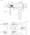
- Fig. 1 is a schematic configuration diagram illustrating an automatic analyzer to which the present invention is applied.
- reaction containers 2 are circumferentially arranged in a reaction disk 1.
- a plurality of reagent bottles 12 can be disposed on a circumference in a reagent disk 11.
- a sample transport mechanism 19 moving a rack 18 having a sample container mounted thereon is installed between the reaction disk 1 and the reagent disk 11.
- reagent dispensing mechanisms 7, 8, 9, and 10 are installed between the reaction disk 1 and the reagent disk 11.
- sample dispensing mechanisms 13 and 14 which are rotatable, horizontally movable, and vertically movable are installed between the reaction disk 1 and the sample transport mechanism 19, and the sample dispensing mechanisms 13 and 14 respectively include sample dispensing nozzles (abbreviated to sample nozzles) 13a and 14a.
- a pump for a sample 21 is connected to the sample nozzles 13a and 14a.
- the sample nozzles 13a and 14a perform a rotation operation centering on a rotation axis and a horizontal operation of moving on a horizontal movement rail, and perform sample dispensing from the sample container to the reaction container 2.
- a cleaning mechanism 3, a spectrophotometer 4, stirring mechanisms 5 and 6, the reagent disk 11, and the sample transport mechanism 19 are disposed in the vicinity of the reaction disk 1, and a cleaning pump 22 is connected to the cleaning mechanism 3.
- Cleaning tanks 15, 16, 30, 31, 32, and 33 are respectively installed on operation ranges of the reagent dispensing mechanisms 7, 8, 9, and 10, the sample dispensing mechanisms 13 and 14, and the stirring mechanisms 5 and 6.
- a reagent pump 20 is connected to the reagent dispensing mechanisms 7, 8, 9, and 10.
- the sample container accommodating an inspection sample such as blood or urine is mounted on the rack 18 and is carried by the sample transport mechanism 19.
- the mechanisms are connected to a controller 23, and the operation of the mechanisms is controlled by the controller 23.
- the controller 23 has a function as an analysis unit that analyzes the inspection sample within the reaction container 2.
- a coordinate measurement stand 49 is installed on the rack 18 and can be transported to a position for coordinate measurement by the sample transport mechanism 19.
- Fig. 2 is a schematic configuration diagram illustrating the sample dispensing mechanisms 13 and 14 in an example of the present invention.
- the sample dispensing mechanisms 13 and 14 respectively include the sample nozzles 13a and 14a performing suction and discharge of a sample, an arm 44 holding the sample nozzles 13a and 14a, an elastic body 47 elastically supporting the sample nozzles 13a and 14a, a capacitance detector 48 detecting changes in capacitance of the sample nozzles 13a and 14a, a stop position detection plate 45 connected to the sample nozzles 13a and 14a, a stop position detector 46 installed at the arm 44 detecting the movement of the stop position detection plate 45, a vertical mechanism 41 vertically operating the arm 44, a rotating mechanism 42 rotating the arm 44, and a horizontal mechanism 43 horizontally operating the arm 44.
- the stop position detection plate 45 and the stop position detector 46 may serve as both an obstacle detection plate and an obstacle detector or may be provided regardless of each other.
- Fig. 3 is an internal configuration diagram illustrating the controller 23 in the example of the present invention.
- the controller 23 includes a contact determination unit 23a that determines that the sample nozzles 13a and 14a have come into contact with a liquid level or an object in accordance with a capacitance detection signal being supplied from the capacitance detector 48 and changing by a fixed value or more, a memory 23b which is capable of storing any moving amount, a movement detection unit 23c to which a stop position detection signal is supplied from the stop position detector 46, and an operation control unit 23d that controls the operation of the sample nozzles 13a and 14a. Meanwhile, the controller 23 also has a function of controlling the operation of other mechanisms such as the reaction disk 1.
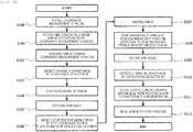
- Fig. 4 illustrates a flow of a method of measuring the elastic contact moving distance 52.
- the coordinate measurement stand 49 is installed at a predetermined position (S100) ( Fig. 5 ).
- the arm 44 is moved to a position above the coordinate measurement stand 49 by the rotating mechanism 42 rotating the arm 44 and the horizontal mechanism 43 horizontally operating the arm 44 (S101).
- the arm 44 and the sample nozzles 13a and 14a descend toward the coordinate measurement stand 49 by the vertical mechanism 41 vertically moving the arm 44 (S102) ( Fig. 6 ).
- the capacitance detector 48 detects a change in capacitance.
- the operation control unit 23d stops the descending operations of the arm 44 and the sample nozzles 13a and 14a (S103, S104) ((a) in Fig. 8(B) ).
- the coordinate measurement stand 49 is preferably made of a conductive material, for example, a metal or conductive plastic.
- a conductive material for example, a metal or conductive plastic.
- the material of the coordinate measurement stand 49 has conductivity higher than that of at least a material used for the reaction container 2.
- the coordinate measurement stand 49 is connected to an earth in order to facilitate detection of a change in capacitance.
- the capacitance detector 48 may be replaced with a piezoelectric member.
- the piezoelectric member In a case where the piezoelectric member is used, the piezoelectric member is installed in such a manner as to support the sample nozzles 13a and 14a, the displacement of the piezoelectric member caused by the sample nozzles 13a and 14a being pressed against the coordinate measurement stand 49 is converted into a voltage, and the contact determination unit 23a determines the voltage.
- the contact determination unit 23a can not only determine a contact between the sample nozzles 13a and 14a and an object in accordance with a signal from the capacitance detector detecting a change in the capacitance of the nozzles but also determine a contact between the sample nozzles 13a and 14a and an object in accordance with a change in voltage due to deformation of the piezoelectric member supporting the nozzles.
- the arm 44 further descends from a state where the tips of the sample nozzles 13a and 14a are in contact with the coordinate measurement stand 49, and the sample nozzles 13a and 14a descend while making an elastic contact, that is, receiving an elastic force of the elastic body 47 (S105) .
- a signal of the stop position detector 46 changes as illustrated in (b) of Fig. 8(A)
- the movement detection unit 23c determines the change
- the operation control unit 23d stops the descending operation of the arm 44 at an arm driving distance a 50 (S106) (the left drawing of Fig. 7 ).
- a sensor such as a photo-interrupter is used as the stop position detector 46.
- the arm 44 starts to ascend from a position illustrated in the left drawing of Fig. 7 by the vertical mechanism 41 (S107).
- the movement detection unit 23c determines the separation, and the operation control unit 23d stops the ascending operation of the arm 44 at an arm driving distance b 51 (S108) (the middle drawing of Fig. 7 ).
- the arm 44 starts to ascend again from a position illustrated in (c) of Fig. 8(A) by the vertical mechanism 41 (S109).
- the capacitance detector 48 detects a change in capacitance as illustrated in (d) of Fig. 8 (B) (S110) (the right drawing of Fig. 7 ).
- a distance from a position where the stop position detection plate 45 separates from the detection region of the stop position detector 46 to a position where the capacitance detector 48 detects a change in capacitance is stored in the memory 23b as the elastic contact moving distance 52 (S111).
- the elastic contact moving distance 52 is determined on the basis of a distance from a boundary position where the stop position detector 46 detects the stop position detection plate 45 to a boundary position where the contact determination unit 23a determines a contact between the nozzles and the object, and the moving distance is stored in the memory 23b.
- the elastic contact moving distance 52 at which the sample nozzles can be positioned at an elastic contact starting point to be described later even when there are variations in the dimensions of the sample nozzles 13a and 14a and variations in the distances of the stop position detector 46 and the stop position detection plate 45.
- the acquisition is performed for each automatic analyzer. In addition, the acquisition is also performed after replacement of the nozzles, and the like are performed.
- Fig. 9 is a schematic view illustrating a moment when the sample nozzles 13a and 14a collide with the reaction container.
- Fig. 10 illustrates changes over time in a force applied when the tips of the sample nozzles 13a and 14a collide with the reaction container 2.
- an upward force is instantaneously applied to the sample nozzles 13a and 14a as illustrated in Fig. 10 .
- a force to be applied to the instantaneously sample nozzles 13a and 14a becomes stronger as the rigidity of the reaction container 2 increases or a descending speed of the arm 44 increases.
- Fig. 11 illustrates movements of the sample nozzles 13a and 14a immediately after collision with the reaction container 2. Since an upward force is instantaneously applied to the sample nozzles 13a and 14a at the time of collision with the reaction container 2 as described above, the sample nozzles move upward immediately after the collision. However, since the sample nozzles 13a and 14a are supported by the elastic body 47, a downward force is immediately applied to push back the sample nozzles 13a and 14a, and the sample nozzles 13a and 14a are eventually stopped while damping vibration.
- a timing at which the stop position detection plate 45 is detected by the stop position detector 46 is determined in accordance with a total speed of a descending speed of the arm 44 toward the reaction container 2 and an upward moving speed immediately after the sample nozzles 13a and 14a collide with the reaction container 2.
- a position where the stop position detection plate 45 is detected by the stop position detector 46 is determined in accordance with an upward moving speed immediately after the sample nozzles 13a and 14a collide with the reaction container 2. Accordingly, since a force (and a speed) to be instantaneously applied to the sample nozzles 13a and 14a becomes stronger as the rigidity of the reaction container 2 increases as described above, a position where the stop position detection plate 45 is detected by the stop position detector 46 is located above when seen from the bottom surface of the reaction container 2.
- Figs. 12 to 14 are diagrams illustrating a method of descending the sample nozzles 13a and 14a to the reaction container 2 in the example of the present invention.
- the sample nozzles 13a and 14a collecting a sample from the sample container are moved to a position above the reaction container 2 by the rotating mechanism 42 rotating the arm 44 and the horizontal mechanism 43 horizontally operating the arm 44 and then descend toward the bottom of the reaction container 2 (S200, S201) ( Fig. 13 ).
- an arm mechanism is ascended by an arm moving distance d 54 until the stop position detection plate 45 separates from a detection range of the stop position detector 46 (S203, S204) (the middle drawing of Fig. 14 ).
- an ascending distance to be input to a motor is sufficiently larger than the above-described arm driving distance b 51.
- the arm 44 is ascended by the elastic contact moving distance 52 described above to move the sample nozzles 13a and 14a to the elastic contact starting point with the bottom surface of the sample container 2 (S205) (the left drawing of Fig. 14 ).
- the sample is discharged (S206).
- the arm 44 is moved to a start position (S207).
- Fig. 15 is a diagram illustrating a method of discharging a sample to the reaction container 2 in the example of the present invention.
- the arm stops descending toward the reaction container 2 it is possible to change a discharging operation start time in accordance with a dispensing amount or time required for dispensing.
- the sample nozzles 13a and 14a are moved upward from time t 0 to time t 2 , illustrated in Fig. 15 (A) , at which the upward movement of the sample nozzles to the elastic contact starting point is terminated as illustrated in Fig. 15(A) .
- the sample nozzles 13a and 14a start to discharge a sample from time t 2 at which the upward movement is terminated.
- the discharge of the sample is completed until time t 3 , and the arm 44 is moved upward to an upper limit point.
- the sample nozzles 13a and 14a are moved upward from time t 0 to time t 1 , illustrated in Fig. 15 (B) , during which the stop position detection plate 45 separates from a detection range of the stop position detector 46 as illustrated in Fig. 15 (B) .
- the sample nozzles 13a and 14a start to discharge a sample from time t 1 at which the upward movement is terminated. Thereafter, the discharge of the sample is completed until time t 3 , and the arm 44 is moved upward to an upper limit point.
- a state where the bending of the sample nozzles 13a and 14a has not yet been suppressed (a state where the sample nozzles are supported by the elastic body) is established at a position where the stop position detection plate 45 separates from the detection range of the stop position detector 46 at time t 1 .
- the position where the stop position detection plate 45 separates from the detection range of the stop position detector 46 is fixed regardless of a difference in rigidity between the reaction containers 2, and thus it is possible to perform sample discharge with high reproducibility even when the sample discharge is started from time t 1 illustrated in Fig. 15 (B) .
- the sample discharge may be started after the sample nozzles are ascended to the elastic contact starting point and are then stopped, or may be started from a position where the stop position detection plate separates from the stop position detector.
- the sample discharge may be started before the sample nozzles are ascended to the elastic contact starting point and are then stopped.
- the controller 23 may determine which of either the control in the former case or the control in the latter case is performed, on the basis of a discharging amount of the sample or a discharging speed of the sample. That is, it is preferable that the control in the former case is applied in a case where a discharging amount of the sample is relatively large or larger than a predetermined amount and the control in the latter case is applied in a case where a discharging speed of the sample is relatively low even when discharging amounts are the same or a discharging speed of the sample is lower than a predetermined speed.
- descending of the arm is stopped at the same time when the stop position detector detects a stop detection plate.
- the arm is stopped after advancing from a position where the stop position detector starts to detect the stop detection plate.
- This additional advance distance is set to be a sufficient distance so that the stop position detector can reliably detect the stop detection plate when the sample nozzles are stopped even when there are variations in stop positions of the sample nozzles due to a difference (variation) in the rigidity of the bottom between the reaction containers.
- setting for ascending the arm by a predetermined distance may be performed to separate the stop position detection plate from the stop position detector.
- a distance at which the stop position detection plate reliably separates from the stop position detector even when there are variations in the above-described stop position is determined, and the arm is ascended by the distance. It is possible to reliably detect that the stop position detection plate has separated from the stop position detector before movement at this distance is terminated with respect to all of the reaction containers in order to ascend the arm at a distance for reliable separation.
- discharge of a sample has been described as an example, but the invention can also be applied to discharge of a reagent and may be applied to a reagent dispensing mechanism.
Abstract
Description
- The present invention relates to an automatic analyzer that analyzes biological samples such as blood and urine, and more particularly, to an automatic analyzer including a dispensing mechanism that dispenses predetermined amounts of sample, reagent, and the like.
- Automatic analyzers that perform quantitative or qualitative analysis of a specific component included in a biological sample such as blood or urine have been indispensable for the present diagnosis because of reproducibility of analysis results, a high processing speed, and the like.
- A measurement method of an automatic analyzer is broadly classified into an analysis method (colorimetry) using a reagent that reacts with an analysis target component in a sample and changes the color of a reaction solution, and an analysis method (immunoassay) for counting markers using a reagent obtained by adding a marker to a material directly or indirectly and specifically coupled to a target component.
- In either of the analysis methods, analysis is performed by mixing a predetermined amount of reagent with a sample. However, in recent years, there have been demands for analyzers capable of reducing the amount of reagent used for analysis in response to requests for reducing analysis costs. A sample to be used for one-time analysis in the present automatic analyzer is an order of one-digit microliter, and it is also required to maintain high dispensing accuracy.
- Regarding microscale dispensing of approximately 1 microliter, in a method disclosed in
PTL 1, a sample is prevented from adhering to the side surface of a sample nozzle by maintaining a fixed gap between the bottom of a reaction container and the tip of a sample nozzle and ascending the sample nozzle while dispensing the sample when the sample is discharged to the reaction container, thereby improving the accuracy of dispensing. - Further, in a method disclosed in
PTL 2, descending of an arm is stopped after a detection plate is inserted into a stop position detector, and a nozzle tip is made to abut against the bottom of a container. Thereafter, the arm ascends by a moving distance stored in a memory in advance, and a sample is discharged to a reaction container. -
- PTL 1:
JP-A-2010-175417 - PTL 2:
JP-A-2013-068540 - In the technique disclosed in
PTL 1, a sample is prevented from adhering to the side surface of the sample nozzle by maintaining a fixed gap between the bottom of the reaction container and the tip of the sample nozzle and ascending the sample nozzle while dispensing the sample when the sample is discharged to the reaction container, thereby improving the accuracy of dispensing. In the above-described method, the sample nozzle and the operation of a pump for a sample have to be synchronized with each other, which results in a difficulty in control. - Further, how a sample discharged from the sample nozzle is wetted and spread at the bottom of the reaction container varies depending on a change in wettability with respect to the sample on the bottom of the reaction container due to stains, scratches, or the like or the influence of residual water after cleaning the reaction container. Accordingly, it is extremely difficult to control a distance between the nozzle tip and the bottom of the reaction container and a distance between the liquid level of the discharged sample and the bottom of the reaction container at the same level. In addition, since the sample nozzle performs an ascending operation while discharging a sample, there is a possibility that vibration of the sample nozzle accompanying the ascending operation may affect the accuracy of dispensing.
- In the technique disclosed in
PTL 2, a moving distance of the arm from when the sample nozzle is brought into contact with a coordinate measurement stand to when the stop position detector detects a stop position detection plate is calculated and stored in the memory. Descending of the arm when dispensing a sample to the reaction container is stopped by the stop position detector detecting the stop position detection plate. Thereafter, the arm ascends by the moving distance stored in the memory to discharge the sample. The purpose of this operation is to stop the sample nozzle on the bottom surface of the reaction container in a state where bending (deflection) of the sample nozzle is suppressed. - However, actual reaction containers individually have different rigidities depending on a fixing method or the like. For example, when the sample nozzle collides with the bottom of a reaction container having high rigidity, the sample nozzle itself jumps up to the top due to an impact of the collision. Since the arm stops descending by the stop position detector detecting the stop position detection plate, the arm in the reaction container having high rigidity is stopped at the higher position than in the reaction container having low rigidity. However, the arm ascends by a moving amount stored in the memory in advance by the above-described method, regardless of the actual stop position of the arm. Accordingly, it is extremely difficult to make bending (deflection) of the sample nozzle uniform when discharging a sample in all of the reaction containers. Particularly, in microscale dispensing, a difference in the magnitude of bending (deflection) of this sample nozzle causes a difference in the amount of sample adhering to the tip of the sample nozzle and the state of discharging of the sample, which may be likely to affect the accuracy of dispensing.
- An object of the present invention is to realize an automatic analyzer and a sample dispensing method in the automatic analyzer which are capable of reducing the influence of individual differences between reaction containers and sample nozzles, controlling an interval between the tip of the sample nozzle and the bottom of the reaction container for each sample dispensing, suppressing the adhesion of a sample to the tip of the sample nozzle, and providing a stable discharging state.
- A representative invention of the present invention is as follows.
- There is provided an automatic analyzer including a nozzle that dispenses any one liquid of a sample and a reagent to a reaction container, a dispensing mechanism that includes an arm supporting the nozzle by an elastic member, and a controller that controls vertical movement and horizontal movement of the arm and analyzes a mixed liquid of a sample and a reagent dispensed into the reaction container, in which the nozzle includes a stop position detection plate, the arm includes a stop position detector detecting the stop position detection plate, and the controller includes a memory capable of storing a moving distance of the arm, and the controller stops moving the arm when the stop position detector detects the stop position detection plate during downward movement of the arm, moves the arm by the moving distance stored in the memory in advance and then stops the arm in a subsequent upward movement with a position where the stop position detection plate separates from the stop position detector as a starting point, and performs control such that the liquid is discharged in a state where the arm is stopped.
- According to the present invention, it is possible to discharge a sample so as to be reliably wetted and spread with respect to the bottom of a reaction container, regardless of individual differences between reaction containers and sample nozzles.
-
-
Fig. 1 is a schematic configuration diagram illustrating an automatic analyzer to which the present invention is applied. -
Fig. 2 is a schematic configuration diagram illustratingsample dispensing mechanisms -
Fig. 3 is an internal configuration diagram illustrating acontroller 23 in the example of the present invention. -
Fig. 4 is a diagram illustrating a method of measuring an elasticcontact moving distance 52 in the example of the present invention. -
Fig. 5 is a diagram illustrating a method of measuring the elasticcontact moving distance 52 in the example of the present invention. -
Fig. 6 is a diagram illustrating a method of measuring the elasticcontact moving distance 52 in the example of the present invention. -
Fig. 7 is a diagram illustrating a method of measuring the elasticcontact moving distance 52 in the example of the present invention. -
Fig. 8 is a diagram illustrating a relationship between an arm driving distance and an output signal of each of a stop position detector and a capacitance detector. -
Fig. 9 is a diagram illustrating a method of discharging a sample to areaction container 2 in the example of the present invention. -
Fig. 10 is a diagram illustrating a force applied when a nozzle collides with a reaction container. -
Fig. 11 is a diagram illustrating a moving distance after the nozzle collides with the reaction container. -
Fig. 12 is a diagram illustrating a method of discharging a sample to thereaction container 2 in the example of the present invention. -
Fig. 13 is a diagram illustrating a method of discharging a sample to thereaction container 2 in the example of the present invention. -
Fig. 14 is a diagram illustrating a method of discharging a sample to thereaction container 2 in the example of the present invention. -
Fig. 15 is a diagram illustrating a method of discharging a sample to thereaction container 2 in the example of the present invention. - Hereinafter, an example of the present invention will be described with reference to the accompanying drawings.
-
Fig. 1 is a schematic configuration diagram illustrating an automatic analyzer to which the present invention is applied. InFig. 1 ,reaction containers 2 are circumferentially arranged in areaction disk 1. A plurality ofreagent bottles 12 can be disposed on a circumference in areagent disk 11. Asample transport mechanism 19 moving arack 18 having a sample container mounted thereon is installed between thereaction disk 1 and thereagent disk 11. Further,reagent dispensing mechanisms reaction disk 1 and thereagent disk 11. In addition,sample dispensing mechanisms reaction disk 1 and thesample transport mechanism 19, and thesample dispensing mechanisms sample 21 is connected to thesample nozzles sample nozzles reaction container 2. - A
cleaning mechanism 3, aspectrophotometer 4,stirring mechanisms reagent disk 11, and thesample transport mechanism 19 are disposed in the vicinity of thereaction disk 1, and acleaning pump 22 is connected to thecleaning mechanism 3.Cleaning tanks reagent dispensing mechanisms sample dispensing mechanisms stirring mechanisms reagent pump 20 is connected to thereagent dispensing mechanisms - The sample container accommodating an inspection sample such as blood or urine is mounted on the
rack 18 and is carried by thesample transport mechanism 19. In addition, the mechanisms are connected to acontroller 23, and the operation of the mechanisms is controlled by thecontroller 23. In addition, thecontroller 23 has a function as an analysis unit that analyzes the inspection sample within thereaction container 2. A coordinate measurement stand 49 is installed on therack 18 and can be transported to a position for coordinate measurement by thesample transport mechanism 19. -
Fig. 2 is a schematic configuration diagram illustrating thesample dispensing mechanisms Fig. 2 , thesample dispensing mechanisms sample nozzles arm 44 holding thesample nozzles elastic body 47 elastically supporting thesample nozzles capacitance detector 48 detecting changes in capacitance of thesample nozzles position detection plate 45 connected to thesample nozzles stop position detector 46 installed at thearm 44 detecting the movement of the stopposition detection plate 45, avertical mechanism 41 vertically operating thearm 44, arotating mechanism 42 rotating thearm 44, and ahorizontal mechanism 43 horizontally operating thearm 44. Meanwhile, the stopposition detection plate 45 and thestop position detector 46 may serve as both an obstacle detection plate and an obstacle detector or may be provided regardless of each other. -
Fig. 3 is an internal configuration diagram illustrating thecontroller 23 in the example of the present invention. InFig. 3 , thecontroller 23 includes acontact determination unit 23a that determines that thesample nozzles capacitance detector 48 and changing by a fixed value or more, amemory 23b which is capable of storing any moving amount, amovement detection unit 23c to which a stop position detection signal is supplied from thestop position detector 46, and anoperation control unit 23d that controls the operation of thesample nozzles controller 23 also has a function of controlling the operation of other mechanisms such as thereaction disk 1. - Next, a method of measuring an elastic
contact moving distance 52 in the example of the present invention will be described with reference toFigs. 4 to 8 . -
Fig. 4 illustrates a flow of a method of measuring the elasticcontact moving distance 52. - First, the coordinate measurement stand 49 is installed at a predetermined position (S100) (
Fig. 5 ). Next, thearm 44 is moved to a position above the coordinate measurement stand 49 by the rotatingmechanism 42 rotating thearm 44 and thehorizontal mechanism 43 horizontally operating the arm 44 (S101). Thearm 44 and thesample nozzles vertical mechanism 41 vertically moving the arm 44 (S102) (Fig. 6 ). - Next, when the tips of the
sample nozzles measurement stand 49, thecapacitance detector 48 detects a change in capacitance. When thecontact determination unit 23a determines the change, theoperation control unit 23d stops the descending operations of thearm 44 and thesample nozzles Fig. 8(B) ). - Meanwhile, in order to measure a change in capacitance, the coordinate measurement stand 49 is preferably made of a conductive material, for example, a metal or conductive plastic. The reason why the coordinate measurement stand 49 is made of a conductive material is that a change in capacitance is easily detected when a contact with the coordinate measurement stand occurs. Since it is difficult to determine a contact with the bottom of the
reaction container 2 using thecapacitance detector 48, it is preferable that the material of the coordinate measurement stand 49 has conductivity higher than that of at least a material used for thereaction container 2. Further, it is preferable that the coordinate measurement stand 49 is connected to an earth in order to facilitate detection of a change in capacitance. In addition, thecapacitance detector 48 may be replaced with a piezoelectric member. In a case where the piezoelectric member is used, the piezoelectric member is installed in such a manner as to support thesample nozzles sample nozzles contact determination unit 23a determines the voltage. In this manner, thecontact determination unit 23a can not only determine a contact between thesample nozzles sample nozzles - Next, the
arm 44 further descends from a state where the tips of thesample nozzles measurement stand 49, and thesample nozzles position detection plate 45 enters a detection region of thestop position detector 46, a signal of thestop position detector 46 changes as illustrated in (b) ofFig. 8(A) , themovement detection unit 23c determines the change, and theoperation control unit 23d stops the descending operation of thearm 44 at an arm driving distance a 50 (S106) (the left drawing ofFig. 7 ). It is conceivable that a sensor such as a photo-interrupter is used as thestop position detector 46. - Next, the
arm 44 starts to ascend from a position illustrated in the left drawing ofFig. 7 by the vertical mechanism 41 (S107). In addition, as illustrated in (c) ofFig. 8 (A) , when the stopposition detection plate 45 separates from a detection range of thestop position detector 46, themovement detection unit 23c determines the separation, and theoperation control unit 23d stops the ascending operation of thearm 44 at an arm driving distance b 51 (S108) (the middle drawing ofFig. 7 ). - The
arm 44 starts to ascend again from a position illustrated in (c) ofFig. 8(A) by the vertical mechanism 41 (S109). When the tips of thesample nozzles measurement stand 49, thecapacitance detector 48 detects a change in capacitance as illustrated in (d) ofFig. 8 (B) (S110) (the right drawing ofFig. 7 ). A distance from a position where the stopposition detection plate 45 separates from the detection region of thestop position detector 46 to a position where thecapacitance detector 48 detects a change in capacitance is stored in thememory 23b as the elastic contact moving distance 52 (S111). In other words, the elasticcontact moving distance 52 is determined on the basis of a distance from a boundary position where thestop position detector 46 detects the stopposition detection plate 45 to a boundary position where thecontact determination unit 23a determines a contact between the nozzles and the object, and the moving distance is stored in thememory 23b. - By the above-described measurement method, it is possible to acquire the elastic
contact moving distance 52 at which the sample nozzles can be positioned at an elastic contact starting point to be described later, even when there are variations in the dimensions of thesample nozzles stop position detector 46 and the stopposition detection plate 45. The acquisition is performed for each automatic analyzer. In addition, the acquisition is also performed after replacement of the nozzles, and the like are performed. - Finally, the
arm 44 is moved to a start position (S112) . - Next, movements of the
sample nozzles sample nozzles reaction container 2 will be described. Thereaction containers 2 have different rigidities due to factors such as a method of fixing to thereaction disk 1.Fig. 9 is a schematic view illustrating a moment when thesample nozzles -
Fig. 10 illustrates changes over time in a force applied when the tips of thesample nozzles reaction container 2. When the tips of thesample nozzles reaction container 2, an upward force is instantaneously applied to thesample nozzles Fig. 10 . Meanwhile, a force to be applied to the instantaneously samplenozzles reaction container 2 increases or a descending speed of thearm 44 increases. -
Fig. 11 illustrates movements of thesample nozzles reaction container 2. Since an upward force is instantaneously applied to thesample nozzles reaction container 2 as described above, the sample nozzles move upward immediately after the collision. However, since thesample nozzles elastic body 47, a downward force is immediately applied to push back thesample nozzles sample nozzles - In the actual operation, the
arm 44 also descends toward thereaction container 2. For this reason, a timing at which the stopposition detection plate 45 is detected by thestop position detector 46 is determined in accordance with a total speed of a descending speed of thearm 44 toward thereaction container 2 and an upward moving speed immediately after thesample nozzles reaction container 2. - Here, since a descending speed of the
arm 44 when the arm collides with thereaction container 2 is a fixed speed, a position where the stopposition detection plate 45 is detected by thestop position detector 46 is determined in accordance with an upward moving speed immediately after thesample nozzles reaction container 2. Accordingly, since a force (and a speed) to be instantaneously applied to thesample nozzles reaction container 2 increases as described above, a position where the stopposition detection plate 45 is detected by thestop position detector 46 is located above when seen from the bottom surface of thereaction container 2. -
Figs. 12 to 14 are diagrams illustrating a method of descending thesample nozzles reaction container 2 in the example of the present invention. Thesample nozzles reaction container 2 by the rotatingmechanism 42 rotating thearm 44 and thehorizontal mechanism 43 horizontally operating thearm 44 and then descend toward the bottom of the reaction container 2 (S200, S201) (Fig. 13 ). - Since a solution within the
reaction container 2 is measured by thespectrophotometer 4, glass or plastic having a high transmittance is mainly used as the material of the reaction container, and it is difficult to determine a contact between thesample nozzles reaction container 2 by thecapacitance detector 48. - Consequently, after the
sample nozzles reaction container 2 and then make an elastic contact, thearm 44 descends and is then stopped at a position where thestop position detector 46 detects a stop position detection plate 45 (S202) (the left drawing ofFig. 14 ). An arm moving distance c from a position at the moment when thesample nozzles reaction container 2 to a position where the sample nozzles are stopped is denoted by 53. - Next, an arm mechanism is ascended by an arm moving
distance d 54 until the stopposition detection plate 45 separates from a detection range of the stop position detector 46 (S203, S204) (the middle drawing ofFig. 14 ). In this case, it is assumed that an ascending distance to be input to a motor is sufficiently larger than the above-described armdriving distance b 51. By adopting this method, it is possible to operate the arm to a position where thestop position detector 46 cancels detection from the stopposition detection plate 45, regardless of a difference in a stop position of the arm which is caused by a difference in rigidity between thereaction containers 2. - Next, the
arm 44 is ascended by the elasticcontact moving distance 52 described above to move thesample nozzles Fig. 14 ). The sample is discharged (S206). In addition, thearm 44 is moved to a start position (S207). - By adopting the above-described method, it is possible to perform operation control so that the tips of the
sample nozzles sample container 2, regardless of variations in thesample nozzles reaction container 2, and a difference in rigidity. Thereby, it is possible to discharge a sample so as to be reliably wetted and spread with respect to the bottom of the reaction container, regardless of individual differences between the reaction containers and the sample nozzles. - In addition, since the bottom surface of the
reaction container 2 and thesample nozzles sample nozzles sample nozzles sample nozzles -
Fig. 15 is a diagram illustrating a method of discharging a sample to thereaction container 2 in the example of the present invention. After the arm stops descending toward thereaction container 2, it is possible to change a discharging operation start time in accordance with a dispensing amount or time required for dispensing. When there is a sufficient operation time for thesample nozzles sample nozzles Fig. 15 (A) , at which the upward movement of the sample nozzles to the elastic contact starting point is terminated as illustrated inFig. 15(A) . Next, thesample nozzles arm 44 is moved upward to an upper limit point. - On the other hand, when there is no time to perform a discharging operation, the
sample nozzles Fig. 15 (B) , during which the stopposition detection plate 45 separates from a detection range of thestop position detector 46 as illustrated inFig. 15 (B) . Next, thesample nozzles arm 44 is moved upward to an upper limit point. A state where the bending of thesample nozzles position detection plate 45 separates from the detection range of thestop position detector 46 at time t1. However, the position where the stopposition detection plate 45 separates from the detection range of thestop position detector 46 is fixed regardless of a difference in rigidity between thereaction containers 2, and thus it is possible to perform sample discharge with high reproducibility even when the sample discharge is started from time t1 illustrated inFig. 15 (B) . - In this manner, the sample discharge may be started after the sample nozzles are ascended to the elastic contact starting point and are then stopped, or may be started from a position where the stop position detection plate separates from the stop position detector. In the latter case, it is possible to reduce time to discharge a sample or reduce time until the discharge is completed, as compared to the former case. Meanwhile, in the latter case, the sample discharge may be started before the sample nozzles are ascended to the elastic contact starting point and are then stopped.
- In addition, the
controller 23 may determine which of either the control in the former case or the control in the latter case is performed, on the basis of a discharging amount of the sample or a discharging speed of the sample. That is, it is preferable that the control in the former case is applied in a case where a discharging amount of the sample is relatively large or larger than a predetermined amount and the control in the latter case is applied in a case where a discharging speed of the sample is relatively low even when discharging amounts are the same or a discharging speed of the sample is lower than a predetermined speed. - Meanwhile, in
Fig. 8 , descending of the arm is stopped at the same time when the stop position detector detects a stop detection plate. However, actually, the arm is stopped after advancing from a position where the stop position detector starts to detect the stop detection plate. This additional advance distance is set to be a sufficient distance so that the stop position detector can reliably detect the stop detection plate when the sample nozzles are stopped even when there are variations in stop positions of the sample nozzles due to a difference (variation) in the rigidity of the bottom between the reaction containers. In addition, when the arm is ascended, setting for ascending the arm by a predetermined distance may be performed to separate the stop position detection plate from the stop position detector. In this case, a distance at which the stop position detection plate reliably separates from the stop position detector even when there are variations in the above-described stop position is determined, and the arm is ascended by the distance. It is possible to reliably detect that the stop position detection plate has separated from the stop position detector before movement at this distance is terminated with respect to all of the reaction containers in order to ascend the arm at a distance for reliable separation. Further, in order to ascend the arm by the same elastic contact moving distance with respect to all of the reaction containers with a position where the stop position detection plate reliably separates from the stop position detector as a starting point, it is possible to substantially eliminate an influence due to the above-described difference (variation) in the rigidity of the bottom between the reaction containers and to make bending (deflection) at the time of sample discharge of the sample nozzles uniform in all of the reaction containers, regardless of individual differences between the reaction containers and the sample nozzles. - In the example, discharge of a sample has been described as an example, but the invention can also be applied to discharge of a reagent and may be applied to a reagent dispensing mechanism.
-
- 1:
- reaction disk
- 2:
- reaction container
- 3:
- cleaning mechanism
- 4:
- spectrophotometer
- 5, 6:
- stirring mechanism
- 7, 8, 9, 10:
- reagent dispensing mechanism
- 11:
- reagent disk
- 12:
- reagent bottle
- 13, 14:
- sample dispensing mechanism
- 13a, 14a:
- sample nozzle
- 15, 16:
- cleaning tank
- 18:
- rack
- 19:
- sample transport mechanism
- 20:
- reagent pump
- 21:
- pump for a sample
- 22:
- cleaning pump
- 23:
- controller
- 23a:
- contact determination unit
- 23b:
- memory
- 23c:
- movement detection unit
- 23d:
- operation control unit
- 30, 31, 32, 33:
- cleaning tank
- 41:
- vertical mechanism
- 42:
- rotating mechanism
- 43:
- horizontal mechanism
- 44:
- arm
- 45:
- stop position detection plate
- 46:
- stop position detector
- 47:
- elastic body
- 48:
- capacitance detector
- 49:
- coordinate measurement stand
- 50:
- arm driving distance a
- 51:
- arm driving distance b
- 52:
- elastic contact moving distance
- 53:
- arm driving distance c
- 54:
- arm driving distance d
Claims (5)
- An automatic analyzer comprising:a nozzle that dispenses any one liquid of a sample and a reagent to a reaction container;a dispensing mechanism that includes an arm supporting the nozzle by an elastic member; anda controller that controls vertical movement and horizontal movement of the arm and analyzes a mixed liquid of a sample and a reagent dispensed into the reaction container, whereinthe nozzle includes a stop position detection plate, the arm includes a stop position detector detecting the stop position detection plate, and the controller includes a memory capable of storing a moving distance of the arm, andthe controller stops moving the arm when the stop position detector detects the stop position detection plate during downward movement of the arm, moves the arm by the moving distance stored in the memory in advance and then stops the arm in a subsequent upward movement with a position where the stop position detection plate separates from the stop position detector as a starting point, and performs control such that the liquid is discharged in a state where the arm is stopped.
- The automatic analyzer according to claim 1, further comprising:a contact determination unit that determines that the nozzle is in contact with an object, whereinthe moving distance stored in the memory is determined on the basis of a distance between a boundary position where the stop position detector detects the stop position detection plate and a boundary position where the contact determination unit determines a contact between the nozzle and the object.
- The automatic analyzer according to claim 2, wherein
the contact determination unit determines a contact between the nozzle and the object in accordance with a signal received from a capacitance detector that detects a change in capacitance of the nozzle. - The automatic analyzer according to claim 2, wherein
the contact determination unit determines a contact between the nozzle and the object in accordance with a change in voltage due to deformation of a piezoelectric member supporting the nozzle. - The automatic analyzer according to claim 1, wherein
the controller performs first control for discharging the liquid in a state where the arm is moved upward by the moving distance and is then stopped with the position where the stop position detection plate separates from the stop position detector as a starting point, and second control for discharging the liquid before the arm is moved upward by the moving distance and is then stopped, and
the controller performs either the first control or the second control on the basis of a discharging amount of the liquid or a discharging speed of the liquid.
Applications Claiming Priority (2)
| Application Number | Priority Date | Filing Date | Title |
|---|---|---|---|
| JP2016183626 | 2016-09-21 | ||
| PCT/JP2017/028359 WO2018055929A1 (en) | 2016-09-21 | 2017-08-04 | Automatic analysis device |
Publications (3)
| Publication Number | Publication Date |
|---|---|
| EP3517974A1 true EP3517974A1 (en) | 2019-07-31 |
| EP3517974A4 EP3517974A4 (en) | 2020-05-13 |
| EP3517974B1 EP3517974B1 (en) | 2023-04-26 |
Family
ID=61689867
Family Applications (1)
| Application Number | Title | Priority Date | Filing Date |
|---|---|---|---|
| EP17852710.7A Active EP3517974B1 (en) | 2016-09-21 | 2017-08-04 | Automatic analyzer |
Country Status (5)
| Country | Link |
|---|---|
| US (1) | US11009515B2 (en) |
| EP (1) | EP3517974B1 (en) |
| JP (1) | JP6854292B2 (en) |
| CN (1) | CN109690325B (en) |
| WO (1) | WO2018055929A1 (en) |
Cited By (3)
| Publication number | Priority date | Publication date | Assignee | Title |
|---|---|---|---|---|
| WO2021102043A1 (en) * | 2019-11-21 | 2021-05-27 | 10X Genomics, Inc. | Automated library generator |
| EP4184176A1 (en) | 2021-11-17 | 2023-05-24 | Roche Diagnostics GmbH | Method for detection of a bottom of at least one well |
| US11857981B2 (en) | 2019-12-23 | 2024-01-02 | 10X Genomics, Inc. | Magnetic separator for an automated single cell sequencing system |
Families Citing this family (2)
| Publication number | Priority date | Publication date | Assignee | Title |
|---|---|---|---|---|
| JP7243607B2 (en) * | 2019-12-12 | 2023-03-22 | 株式会社島津製作所 | Biochemical analyzer and biochemical analysis method |
| WO2022070459A1 (en) * | 2020-09-29 | 2022-04-07 | 株式会社日立ハイテク | Automated analyzer |
Family Cites Families (14)
| Publication number | Priority date | Publication date | Assignee | Title |
|---|---|---|---|---|
| US4864856A (en) * | 1986-07-14 | 1989-09-12 | Fuji Photo Film Co., Ltd. | Liquid level detecting device |
| JP3486495B2 (en) * | 1995-12-04 | 2004-01-13 | オリンパス株式会社 | Medical analyzer |
| JPH11304819A (en) * | 1998-04-23 | 1999-11-05 | Aloka Co Ltd | Nozzle apparatus |
| JP3672742B2 (en) * | 1998-08-13 | 2005-07-20 | 日本電子株式会社 | Pipette nozzle safety device in analyzer |
| US6270726B1 (en) * | 1999-09-30 | 2001-08-07 | Dpc Cirrus, Inc. | Tube bottom sensing for small fluid samples |
| JP2001183380A (en) * | 1999-12-28 | 2001-07-06 | Olympus Optical Co Ltd | Automatic analyzing apparatus |
| JP2003344426A (en) * | 2002-05-22 | 2003-12-03 | Aloka Co Ltd | Dispensation device |
| JP4646311B2 (en) * | 2005-11-22 | 2011-03-09 | 株式会社スギノマシン | Nozzle tip reference height position adjustment device and sampling device |
| JP5210902B2 (en) * | 2009-01-30 | 2013-06-12 | 株式会社日立ハイテクノロジーズ | Automatic analyzer and analysis method using automatic analyzer |
| JP5275182B2 (en) * | 2009-09-11 | 2013-08-28 | 株式会社日立ハイテクノロジーズ | Dispensing device and analyzer |
| JP5295069B2 (en) * | 2009-10-09 | 2013-09-18 | ベックマン コールター, インコーポレイテッド | Dispensing device, analyzer, and dispensing method |
| JP5514582B2 (en) * | 2010-02-24 | 2014-06-04 | 株式会社日立製作所 | Liquid suction device |
| JP5752545B2 (en) * | 2011-09-22 | 2015-07-22 | 株式会社日立ハイテクノロジーズ | Automatic analyzer |
| CN105829896B (en) * | 2014-01-07 | 2019-01-22 | 株式会社日立高新技术 | Automatic analysing apparatus |
-
2017
- 2017-08-04 JP JP2018540678A patent/JP6854292B2/en active Active
- 2017-08-04 EP EP17852710.7A patent/EP3517974B1/en active Active
- 2017-08-04 CN CN201780056407.8A patent/CN109690325B/en active Active
- 2017-08-04 WO PCT/JP2017/028359 patent/WO2018055929A1/en unknown
- 2017-08-04 US US16/331,583 patent/US11009515B2/en active Active
Cited By (3)
| Publication number | Priority date | Publication date | Assignee | Title |
|---|---|---|---|---|
| WO2021102043A1 (en) * | 2019-11-21 | 2021-05-27 | 10X Genomics, Inc. | Automated library generator |
| US11857981B2 (en) | 2019-12-23 | 2024-01-02 | 10X Genomics, Inc. | Magnetic separator for an automated single cell sequencing system |
| EP4184176A1 (en) | 2021-11-17 | 2023-05-24 | Roche Diagnostics GmbH | Method for detection of a bottom of at least one well |
Also Published As
| Publication number | Publication date |
|---|---|
| EP3517974A4 (en) | 2020-05-13 |
| US20190219604A1 (en) | 2019-07-18 |
| CN109690325A (en) | 2019-04-26 |
| WO2018055929A1 (en) | 2018-03-29 |
| JPWO2018055929A1 (en) | 2019-07-04 |
| US11009515B2 (en) | 2021-05-18 |
| CN109690325B (en) | 2022-09-06 |
| EP3517974B1 (en) | 2023-04-26 |
| JP6854292B2 (en) | 2021-04-07 |
Similar Documents
| Publication | Publication Date | Title |
|---|---|---|
| EP3517974B1 (en) | Automatic analyzer | |
| JP5686744B2 (en) | Automatic analyzer | |
| JP5752545B2 (en) | Automatic analyzer | |
| US9228946B2 (en) | Analyzer, method for determining a dispensed liquid amount, and non-transitory computer readable medium | |
| JP6280777B2 (en) | Analysis device and liquid level detection method in analysis device | |
| EP2648000B1 (en) | Automatic analysis apparatus | |
| EP2720045B1 (en) | Autoanalyzer | |
| WO2006123771A1 (en) | Method of detecting dispensed quantity, and liquid suction monitoring dispensing apparatus | |
| EP2878955A1 (en) | Automated analyzer | |
| JP3674503B2 (en) | Automatic analyzer and liquid level detection method of automatic analyzer | |
| JP3907819B2 (en) | Liquid level detector | |
| US7439076B1 (en) | Liquid dispensing method and device | |
| JPH06230014A (en) | Automatic analysis device | |
| JP3120180U (en) | Automatic analyzer | |
| JP2016186429A (en) | Dispensing device, automatic analysis device, and dispensing method | |
| JPWO2015115200A1 (en) | Automatic analyzer | |
| JPH02243960A (en) | System for operating dispenser of analysis apparatus | |
| CN114746759A (en) | Automatic analyzer | |
| JPH0560768A (en) | Method and apparatus for sampling specimen in automatic analyzer | |
| JP2000046624A (en) | Analyser having liquid residual quantity detecting function | |
| WO2010150502A1 (en) | Automatic analysis device | |
| JP2003254983A (en) | Level detection apparatus and automatic analyzer using the same | |
| WO2024075437A1 (en) | Dispensing device and probe state confirmation method | |
| JP6449008B2 (en) | Automatic analyzer | |
| JPH06148207A (en) | Sample dispensing system of automatic chemical analyzer |
Legal Events
| Date | Code | Title | Description |
|---|---|---|---|
| STAA | Information on the status of an ep patent application or granted ep patent |
Free format text: STATUS: THE INTERNATIONAL PUBLICATION HAS BEEN MADE |
|
| PUAI | Public reference made under article 153(3) epc to a published international application that has entered the european phase |
Free format text: ORIGINAL CODE: 0009012 |
|
| STAA | Information on the status of an ep patent application or granted ep patent |
Free format text: STATUS: REQUEST FOR EXAMINATION WAS MADE |
|
| 17P | Request for examination filed |
Effective date: 20190312 |
|
| AK | Designated contracting states |
Kind code of ref document: A1 Designated state(s): AL AT BE BG CH CY CZ DE DK EE ES FI FR GB GR HR HU IE IS IT LI LT LU LV MC MK MT NL NO PL PT RO RS SE SI SK SM TR |
|
| AX | Request for extension of the european patent |
Extension state: BA ME |
|
| DAV | Request for validation of the european patent (deleted) | ||
| DAX | Request for extension of the european patent (deleted) | ||
| A4 | Supplementary search report drawn up and despatched |
Effective date: 20200417 |
|
| RIC1 | Information provided on ipc code assigned before grant |
Ipc: G01N 35/10 20060101AFI20200409BHEP Ipc: G01N 35/00 20060101ALI20200409BHEP |
|
| RAP1 | Party data changed (applicant data changed or rights of an application transferred) |
Owner name: HITACHI HIGH-TECH CORPORATION |
|
| STAA | Information on the status of an ep patent application or granted ep patent |
Free format text: STATUS: EXAMINATION IS IN PROGRESS |
|
| 17Q | First examination report despatched |
Effective date: 20220524 |
|
| GRAP | Despatch of communication of intention to grant a patent |
Free format text: ORIGINAL CODE: EPIDOSNIGR1 |
|
| STAA | Information on the status of an ep patent application or granted ep patent |
Free format text: STATUS: GRANT OF PATENT IS INTENDED |
|
| INTG | Intention to grant announced |
Effective date: 20221124 |
|
| GRAS | Grant fee paid |
Free format text: ORIGINAL CODE: EPIDOSNIGR3 |
|
| GRAA | (expected) grant |
Free format text: ORIGINAL CODE: 0009210 |
|
| STAA | Information on the status of an ep patent application or granted ep patent |
Free format text: STATUS: THE PATENT HAS BEEN GRANTED |
|
| RIN1 | Information on inventor provided before grant (corrected) |
Inventor name: FUKAYA, MASASHI Inventor name: TAKADA, EIICHIRO Inventor name: TOKIEDA, HITOSHI Inventor name: TAKAHASHI, TAKUYA |
|
| AK | Designated contracting states |
Kind code of ref document: B1 Designated state(s): AL AT BE BG CH CY CZ DE DK EE ES FI FR GB GR HR HU IE IS IT LI LT LU LV MC MK MT NL NO PL PT RO RS SE SI SK SM TR |
|
| REG | Reference to a national code |
Ref country code: GB Ref legal event code: FG4D |
|
| REG | Reference to a national code |
Ref country code: CH Ref legal event code: EP |
|
| REG | Reference to a national code |
Ref country code: DE Ref legal event code: R096 Ref document number: 602017068151 Country of ref document: DE |
|
| REG | Reference to a national code |
Ref country code: AT Ref legal event code: REF Ref document number: 1563188 Country of ref document: AT Kind code of ref document: T Effective date: 20230515 |
|
| REG | Reference to a national code |
Ref country code: IE Ref legal event code: FG4D |
|
| REG | Reference to a national code |
Ref country code: LT Ref legal event code: MG9D |
|
| REG | Reference to a national code |
Ref country code: NL Ref legal event code: MP Effective date: 20230426 |
|
| REG | Reference to a national code |
Ref country code: AT Ref legal event code: MK05 Ref document number: 1563188 Country of ref document: AT Kind code of ref document: T Effective date: 20230426 |
|
| PG25 | Lapsed in a contracting state [announced via postgrant information from national office to epo] |
Ref country code: NL Free format text: LAPSE BECAUSE OF FAILURE TO SUBMIT A TRANSLATION OF THE DESCRIPTION OR TO PAY THE FEE WITHIN THE PRESCRIBED TIME-LIMIT Effective date: 20230426 |
|
| PG25 | Lapsed in a contracting state [announced via postgrant information from national office to epo] |
Ref country code: SE Free format text: LAPSE BECAUSE OF FAILURE TO SUBMIT A TRANSLATION OF THE DESCRIPTION OR TO PAY THE FEE WITHIN THE PRESCRIBED TIME-LIMIT Effective date: 20230426 Ref country code: PT Free format text: LAPSE BECAUSE OF FAILURE TO SUBMIT A TRANSLATION OF THE DESCRIPTION OR TO PAY THE FEE WITHIN THE PRESCRIBED TIME-LIMIT Effective date: 20230828 Ref country code: NO Free format text: LAPSE BECAUSE OF FAILURE TO SUBMIT A TRANSLATION OF THE DESCRIPTION OR TO PAY THE FEE WITHIN THE PRESCRIBED TIME-LIMIT Effective date: 20230726 Ref country code: ES Free format text: LAPSE BECAUSE OF FAILURE TO SUBMIT A TRANSLATION OF THE DESCRIPTION OR TO PAY THE FEE WITHIN THE PRESCRIBED TIME-LIMIT Effective date: 20230426 Ref country code: AT Free format text: LAPSE BECAUSE OF FAILURE TO SUBMIT A TRANSLATION OF THE DESCRIPTION OR TO PAY THE FEE WITHIN THE PRESCRIBED TIME-LIMIT Effective date: 20230426 |
|
| PG25 | Lapsed in a contracting state [announced via postgrant information from national office to epo] |
Ref country code: RS Free format text: LAPSE BECAUSE OF FAILURE TO SUBMIT A TRANSLATION OF THE DESCRIPTION OR TO PAY THE FEE WITHIN THE PRESCRIBED TIME-LIMIT Effective date: 20230426 Ref country code: PL Free format text: LAPSE BECAUSE OF FAILURE TO SUBMIT A TRANSLATION OF THE DESCRIPTION OR TO PAY THE FEE WITHIN THE PRESCRIBED TIME-LIMIT Effective date: 20230426 Ref country code: LV Free format text: LAPSE BECAUSE OF FAILURE TO SUBMIT A TRANSLATION OF THE DESCRIPTION OR TO PAY THE FEE WITHIN THE PRESCRIBED TIME-LIMIT Effective date: 20230426 Ref country code: LT Free format text: LAPSE BECAUSE OF FAILURE TO SUBMIT A TRANSLATION OF THE DESCRIPTION OR TO PAY THE FEE WITHIN THE PRESCRIBED TIME-LIMIT Effective date: 20230426 Ref country code: IS Free format text: LAPSE BECAUSE OF FAILURE TO SUBMIT A TRANSLATION OF THE DESCRIPTION OR TO PAY THE FEE WITHIN THE PRESCRIBED TIME-LIMIT Effective date: 20230826 Ref country code: HR Free format text: LAPSE BECAUSE OF FAILURE TO SUBMIT A TRANSLATION OF THE DESCRIPTION OR TO PAY THE FEE WITHIN THE PRESCRIBED TIME-LIMIT Effective date: 20230426 Ref country code: GR Free format text: LAPSE BECAUSE OF FAILURE TO SUBMIT A TRANSLATION OF THE DESCRIPTION OR TO PAY THE FEE WITHIN THE PRESCRIBED TIME-LIMIT Effective date: 20230727 |
|
| PGFP | Annual fee paid to national office [announced via postgrant information from national office to epo] |
Ref country code: FR Payment date: 20230824 Year of fee payment: 7 Ref country code: DE Payment date: 20230822 Year of fee payment: 7 |
|
| PG25 | Lapsed in a contracting state [announced via postgrant information from national office to epo] |
Ref country code: FI Free format text: LAPSE BECAUSE OF FAILURE TO SUBMIT A TRANSLATION OF THE DESCRIPTION OR TO PAY THE FEE WITHIN THE PRESCRIBED TIME-LIMIT Effective date: 20230426 |
|
| PG25 | Lapsed in a contracting state [announced via postgrant information from national office to epo] |
Ref country code: SK Free format text: LAPSE BECAUSE OF FAILURE TO SUBMIT A TRANSLATION OF THE DESCRIPTION OR TO PAY THE FEE WITHIN THE PRESCRIBED TIME-LIMIT Effective date: 20230426 |
|
| REG | Reference to a national code |
Ref country code: DE Ref legal event code: R097 Ref document number: 602017068151 Country of ref document: DE |
|
| PG25 | Lapsed in a contracting state [announced via postgrant information from national office to epo] |
Ref country code: SM Free format text: LAPSE BECAUSE OF FAILURE TO SUBMIT A TRANSLATION OF THE DESCRIPTION OR TO PAY THE FEE WITHIN THE PRESCRIBED TIME-LIMIT Effective date: 20230426 Ref country code: SK Free format text: LAPSE BECAUSE OF FAILURE TO SUBMIT A TRANSLATION OF THE DESCRIPTION OR TO PAY THE FEE WITHIN THE PRESCRIBED TIME-LIMIT Effective date: 20230426 Ref country code: RO Free format text: LAPSE BECAUSE OF FAILURE TO SUBMIT A TRANSLATION OF THE DESCRIPTION OR TO PAY THE FEE WITHIN THE PRESCRIBED TIME-LIMIT Effective date: 20230426 Ref country code: EE Free format text: LAPSE BECAUSE OF FAILURE TO SUBMIT A TRANSLATION OF THE DESCRIPTION OR TO PAY THE FEE WITHIN THE PRESCRIBED TIME-LIMIT Effective date: 20230426 Ref country code: DK Free format text: LAPSE BECAUSE OF FAILURE TO SUBMIT A TRANSLATION OF THE DESCRIPTION OR TO PAY THE FEE WITHIN THE PRESCRIBED TIME-LIMIT Effective date: 20230426 Ref country code: CZ Free format text: LAPSE BECAUSE OF FAILURE TO SUBMIT A TRANSLATION OF THE DESCRIPTION OR TO PAY THE FEE WITHIN THE PRESCRIBED TIME-LIMIT Effective date: 20230426 |
|
| PLBE | No opposition filed within time limit |
Free format text: ORIGINAL CODE: 0009261 |
|
| STAA | Information on the status of an ep patent application or granted ep patent |
Free format text: STATUS: NO OPPOSITION FILED WITHIN TIME LIMIT |
|
| PG25 | Lapsed in a contracting state [announced via postgrant information from national office to epo] |
Ref country code: MC Free format text: LAPSE BECAUSE OF FAILURE TO SUBMIT A TRANSLATION OF THE DESCRIPTION OR TO PAY THE FEE WITHIN THE PRESCRIBED TIME-LIMIT Effective date: 20230426 |
|
| REG | Reference to a national code |
Ref country code: CH Ref legal event code: PL |
|
| PG25 | Lapsed in a contracting state [announced via postgrant information from national office to epo] |
Ref country code: MC Free format text: LAPSE BECAUSE OF FAILURE TO SUBMIT A TRANSLATION OF THE DESCRIPTION OR TO PAY THE FEE WITHIN THE PRESCRIBED TIME-LIMIT Effective date: 20230426 |
|
| 26N | No opposition filed |
Effective date: 20240129 |
|
| PG25 | Lapsed in a contracting state [announced via postgrant information from national office to epo] |
Ref country code: LU Free format text: LAPSE BECAUSE OF NON-PAYMENT OF DUE FEES Effective date: 20230804 |